JP2005034315A - Game machine - Google Patents
Game machine Download PDFInfo
- Publication number
- JP2005034315A JP2005034315A JP2003199380A JP2003199380A JP2005034315A JP 2005034315 A JP2005034315 A JP 2005034315A JP 2003199380 A JP2003199380 A JP 2003199380A JP 2003199380 A JP2003199380 A JP 2003199380A JP 2005034315 A JP2005034315 A JP 2005034315A
- Authority
- JP
- Japan
- Prior art keywords
- effect
- game
- specific game
- specific
- player
- Prior art date
- Legal status (The legal status is an assumption and is not a legal conclusion. Google has not performed a legal analysis and makes no representation as to the accuracy of the status listed.)
- Pending
Links
Images


Abstract
Description
【0001】
【発明の属する技術分野】
本発明はパチンコ機に代表される弾球遊技機、遊技者が操作可能な操作手段を適切に入力したときに大当たりとなるような変動演出を有する遊技機に関する。
【0002】
【従来の技術】
従来のパチンコ機等の遊技機では、遊技領域を構成する遊技盤の中央部に液晶表示器等による画像表示装置を設けたものが一般に知られており、遊技領域に設けられた始動入賞口内に遊技球が入賞したときに、画像表示装置において図柄を変動させた後に停止表示したときの図柄(停止図柄)が、予め設定された当たり図柄であった場合、特別遊技状態(大当たり)を成立させるように構成されている。この特別遊技状態においては遊技領域の下部に設けられた可変入賞口(大入賞口)を開放して遊技球の入賞を容易にして、遊技者が大量の遊技球を獲得できるようになっている。
【0003】
ところで、パチンコ機においては、特別遊技状態が成立するか否かは始動入賞口への遊技球入賞時になされる抽選により決定される。これに対して遊技者が遊技する遊技機を面白く感じる大きな要因として、実際に特別遊技状態に突入するまでの特定演出があり、この演出において特別遊技状態への移行を長く期待させることができる遊技機が求められている。通常、遊技機では特別演出が実行されるまで遊技盤中央部に設けられた画像表示装置で各種特定遊技がなされ、大当たり画像に至る過程での演出に工夫を凝らしている(例えば、特開2000−37519号公報参照)。一方、パチスロ機では、上記特定演出中に遊技者が直接参加できる、具体的には遊技者が直接操作(アクセス)可能なスイッチ等の操作手段(以下、スイッチ装置とも称す)を付与し、遊技者が該操作手段を操作することにより演出図柄の選択ができる構成がなされているが、パチンコ機においてもこのような遊技者が演出に参加できるような構成が求められてきている。
【0004】
【特許文献1】特開2000−37519号公報
【0005】
【発明が解決しようとする課題】
しかしながら、パチスロ機はその遊技機の本質的要素として当落選の帰趨に遊技者のスイッチ操作が直接影響するものであり、これに採用されている上記遊技者参加方法をパチンコ機のように当選又は大当たりするか否かを入賞口への弾球入賞に基づく構成をなしている遊技機にそのまま転用することはできない。詳細には、パチンコ機においてパチスロ機方式の遊技者参加をそのまま採用すれば、スイッチ操作により遊技者が特定演出に参加できることとしても、単に演出図柄を選択できるに過ぎず、特別遊技状態に移行するか否か、すなわち大当たりするか否かに対しては遊技者の操作が及ぶものではなく、遊技者にとっては単に特定演出図柄を自己の好みに合致させるだけであり、遊技者のスイッチ操作技量と遊技者最大の関心事である大当たりするか否かとは無関係なものとなる。この意味でパチンコ機のごとき遊技機では、遊技者が演出に直接参加することにより遊技機への興味を飛躍的に向上せしめる演出を遊技者に提供することができなかった。
【0006】
本発明はこのような問題に鑑みたものであり、特別遊技状態に移行する際に実行される表示装置における特定演出に遊技者が参加でき、且つ遊技者にとって自己の技量により遊技機を特別遊技状態、すなわち大当たりへ至らしめることが可能であると認識させる演出を付与する遊技機を提供することを目的とする。
【0007】
【課題を解決するための手段】
このような目的達成のため、本発明の遊技機では、遊技の進行を制御する遊技制御手段と、遊技の進行にもとづく演出を実行する演出制御手段と、遊技制御手段による遊技の進行にもとづき、図柄が変動表示されてから停止表示するまでの図柄変動過程における表示を実行するための表示装置と、表示装置に演出制御手段により所定の特定遊技演出が出力されているときに遊技者の入力操作により演出態様を変更させるための操作手段とを備え、遊技制御手段は、所定の開始条件により抽選を実行して当たり又はハズレを決定する抽選手段と、抽選の結果が当たりと決定された場合には遊技者に有利な特別遊技を実行する特別遊技実行手段とを有している。また、演出制御手段は、予め設定された所定のタイミングと遊技者が操作手段を入力するタイミングとが合致するか否か判断する操作判定手段とを備えている。さらに、演出制御手段により制御される演出は、少なくとも図柄変動表示過程中に操作手段による操作を可能とする特定遊技演出を含み、特定遊技演出は、予め決定された演出態様と、その演出態様が操作判定手段の判定結果に合致させるための操作合致演出と、操作判定手段による判定結果と抽選手段による抽選結果とが相違する場合に抽選結果に合致させるための特定演出逆転結果演出とを含むように構成している。
【0008】
本発明の遊技機では、通常遊技よりも遊技者にとって有利となる特別遊技状態(大当たり)への移行に遊技者の操作が直接関与することができるような演出が付与されている。まず、特別遊技状態に移行する際に表示装置に表示される図柄変動表示過程で実行される特定遊技演出中に遊技者はスイッチ装置等の操作手段を操作することができ、遊技者の操作タイミングが予め定められたタイミングでなされた場合には大当たりとなるような演出が付加される。これにより、遊技者は自己の技量により大当たりが形成されたように感じることができ、遊技機の遊技性を大幅に向上せしめることが可能となる。しかしながら、上述するように大当たり(特別遊技状態)への移行は、始動口への入賞等、所定の開始条件を満たした場合に抽選され、「当たり」又は「ハズレ」が決定されるものであることが遊技機の必須構成である。従って、抽選により決定された結果と遊技者の操作結果とが合致しない、すなわち遊技者の操作に従った演出のみに委せると演出上の「当たり」又は「ハズレ」と現実の「当たり」又は「ハズレ」とが矛盾することとなり、これを看過すれば遊技者は自己の遊技の如何に関わらず結局は単なる演出が付加されただけの遊技機であるとの認識を有し、従来の遊技機を超えた大きな遊技性を遊技機に付加することはできないものとなる。本発明の遊技機においては、このような矛盾を解消すべく、抽選結果と合致するような演出を事後的に付加(差し込み)することで上記矛盾を解決することとしている。
【0009】
また、演出制御手段は、特定遊技演出を実行するか否かを決定する特定遊技実行決定手段を備え、この特定遊技実行決定手段により特定遊技演出を実行すると決定された場合に特定遊技演出を実行することが好ましい。
【0010】
また、特定遊技演出は、1回の前記図柄変動表示過程において1回以上実行可能であり、演出制御手段は、特定遊技演出を実行する回数を決定する特定遊技演出回数決定手段を更に備え、特定遊技演出決定手段は、特定遊技演出回数決定手段により決定された特定遊技演出回数にもとづき特定遊技演出を実行し、さらに、特定演出逆転結果演出は、特定遊技演出回数決定手段により決定された1回以上の特定遊技演出のうち最後に実行される特定遊技演出以外の特定遊技演出では実行されないことが好ましい。
【0011】
大当たりへの移行の際に付与される図柄変動表示過程において特定遊技演出を複数回実行できることとすると、本発明の遊技機の特徴である遊技者の関与機会が多くなり、遊技機の遊技性がより向上するからである。この場合、問題となるのが各特定遊技演出毎に異なる演出結果が生じた場合(通常、このような場合が多いであろう)に特定遊技演出全体(後述の記載では「特定演出」と称す)の演出結果とどう整合性を持たせるかということである。例えば、各特定遊技演出毎に抽選結果に合致するような上記演出を付加することとすれば、それだけ遊技者の操作結果に相反する演出が付加されることとなり、せっかく特定遊技演出を複数回設け、遊技性を向上させようとしても、遊技者にとっては自己の操作が大当たりへの関与していない事実を認識させる結果を招くこととなる。本発明においては、この点を考慮し原則、各特定遊技演出における遊技者の操作と結果演出とを合致させることとして、遊技者へ自己の関与を感じさせ、抽選結果と操作結果との整合させる演出については最後の特定遊技演出において特定遊技演出全体(特定演出)に対して付加することとしている。このようにすることにより遊技者は少なくとも最後の特定遊技演出以外は自己の操作技量に応じて演出結果が変化する、すなわち大当たりへの自己関与を感じることが可能となる。
【0012】
また、演出制御手段は、特定遊技演出毎に操作手段を操作可能な回数を決定する操作回数決定手段と、操作回数決定手段により決定された操作回数を遊技者に視認させる操作可能回数表示手段とを備え、さらに、遊技者による操作手段の操作毎に、操作回数決定手段は決定された操作回数を1つ減じて再決定することが好ましい。
【0013】
各特定遊技演出毎に遊技者が操作可能な回数を複数回決定することにより、遊技者は大当たりへの挑戦機会が増加するように感じることができる。さらに、特定遊技演出毎に異なる操作機会(操作回数)が決定されることにより、操作回数が多い特定遊技が実行されると遊技者は大当たりへの可能性が高まったかのごとき興奮状態にならしめることとなる。従って、本発明の遊技機では各特定遊技演出毎に遊技者が操作可能な回数を決定し、これを遊技者に視認させるべく操作可能回数表示手段(後述する実施形態におけるリボルバ・ランプ31参照)を設け、遊技者が操作するごとに設定された操作回数を1つ減じるように減算処理し(再決定したと言える)、減算処理後の操作回数に応じた表示を行う(例えば、ランプ31を1つ消灯させる)こととしている。
【0014】
さらに、操作判定手段は、特定遊技演出中の予め定められた時間においては前記操作手段からの入力信号を判定しないことが好ましい。すなわち、特定遊技演出中に操作手段からの操作を無効にする時間帯(予め定められた時間)を設けている。これにより、少なくとも各特定遊技演出の開始、終了までの所定時間のみ遊技者は操作手段することができ、操作手段の操作が特定遊技演出中においてのみ実行される演出であると遊技者に認識させることができるとともに、各特定遊技演出が複数の場合に操作が有効となることをもって特定遊技の開始、終了を遊技者に認識させることができる。
【0015】
【発明の実施の形態】
以下、図面を参照して本発明の好ましい実施形態について説明する。本発明における遊技機の代表例としてのパチンコ機について説明する。なお、詳細には後述するが本パチンコ機では、遊技者がピストルから弾丸を発射してターゲットを被弾させるかのごとき演出が付加されており、遊技者が演出参加できる点に特徴を有している。
【0016】
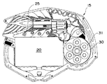
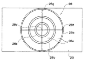
まず最初に、パチンコ機の主要素の構成について説明する。図1を参照すれば本パチンコ機の遊技盤7内の各遊技要素配列を示した略正面図であり、図2を参照すれば図1に示す遊技盤7中央部に配置された画像表示装置20の拡大正面図が示されている(スコープ28は図示せず)。なお、遊技盤7の外枠等については特に後述する要素を除き汎用のパチンコ機を参照すれば理解されよう。
【0017】
パチンコ機の遊技領域10には概ね、後述する画像表示装置20を備える中央役物15と、賞球の払出条件となる複数の一般入賞口11と、賞球の払出条件となるとともに画像表示装置20の図柄の変動開始条件となる始動入賞口12と、後述する特別遊技移行を開放条件とする大入賞口13と、遊技球を回収するアウト口14と、図示しない多数の遊技釘とが設けられている。
【0018】
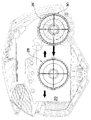
遊技領域10の略中央には、後述する変動パターン等の図柄及び図柄を表示する画像表示装置20が設けられている。また、画像表示器20には可動役物としてのスコープ28が設けられている。このスコープ28は、図3に示すように画像表示器20の前面を左右に往復動する円形外枠28aで形成されており、その内部に同心円状に内枠28b、cや、該内枠28b、cを外枠28aに支持しこれらの枠の中心で交差するように構成された縦及び横軸28f、gが付与されている。また、スコープ28は枠内から表示器20に写された対応する画像を視認することができるようにしている。従って、枠の間28eの隙間に可透性を有するレンズ部材を備える又は枠内に何も備えない。
【0019】
また、図示しないが本パチンコ機では遊技者が直接アクセス可能な押しボタン式等のスイッチ装置(操作手段)23が遊技盤7の外部に付与されている。さらに、画像表示装置20の上方には始動入賞口12への入賞数を表示する保留球ランプ25が配置されており、画像表示装置20の右側部には円形のリボルバ30が配置されており回転させることも可能である。リボルバ30は6個のリボルバ・ランプ31をその周囲に配列している。このリボルバ・ランプ31は後述する特定遊技が開始される毎に各演出パターンに応じて予め定められた個数だけ点灯する。そして、特定遊技中のスイッチ装置23が有効となっている間に遊技者がスイッチ装置23を操作する毎に点灯したランプ31が1個消灯し、又特定遊技毎にリセットされランプ31が全て消灯する。
【0020】
このような構成のパチンコ機において、遊技者が打球ハンドル(図示せず)を操作すると、球受け皿(図示せず)から遊技球が1個ずつ打球発射部(図示せず)に送られ、操作量に応じた強度で遊技領域10に打球が発射される。発射された打球は上述した入賞口11,12或いはアウト口14に流下し、上述した入賞口11,12に入賞した場合には所定の賞球が球受け皿に払い出される。また、上述した入賞口11,12のうち始動入賞口12に打球が入賞すると、所定の賞球が球受け皿に払い出され、画像表示装置20に表示された図柄が変動を開始する。
【0021】
さらに、詳細は後述するが、本発明においては、画像表示装置20において所定時間、所定の動図柄及び図柄(画像)の変動態様を表示が行われた後に、図柄の変動を停止する。このとき、この画像表示装置20に表示された図柄の停止態様が予め定められた当たり装飾図柄の場合には大当たりとなり、大入賞口13が開放されて入賞が容易となった大入賞口13に打球が入賞すると、遊技者には大量の賞球が払い出される。
【0022】
以上のように構成されたパチンコ機に設けられている制御装置について図を用いて説明する。図4は、この制御装置による制御の概略を示すブロック図である。この制御装置は、CPU,ROM,RAM等の種々の電子部品より構成されている遊技制御手段50によりゲームの制御を行う。
【0023】
遊技制御手段50には、始動入賞口12に内蔵された始動口入賞検出装置12aと、大入賞口13に内蔵された大入賞口入賞検出装置13aと、大入賞口13内の特定領域(図示せず)に内蔵された特定領域通過検出装置13b、遊技者が直接アクセス可能な押しボタン式スイッチ等の操作手段23等が電気的に接続しており、これらから検出信号が遊技制御手段50に入力される。
【0024】
遊技制御手段50は、これらの入力された信号に応じて各種作動制御を行うものであり、この制御対象として賞球の払い出しを行う賞球払出装置45と、大入賞口13を開放作動させる大入賞口駆動装置13mと、画像(オブジェクト図柄(画像)と背景画像)を表示する画像表示装置20と、後述する遊技者が実行可能な特定遊技回数を示すリボルバ・ランプ31と、画像表示装置20の前面で左右に滑動するスコープ等の可動役物28が電気的に接続している。これらは全て遊技制御手段50からの制御信号に基づいて作動制御される。なお、その他、保留球ランプ25等が接続される場合も考えられるが、ここでは本発明の主構成要素ではないため省略する。
【0025】
続いて、この遊技制御手段50の制御内容について詳細にはフローチャートを参照しつつ後述するが、ここでは図4、5のブロック図を用いて概説する。遊技制御手段50は、このゲームの制御のために、通常遊技実行手段60と、特別遊技実行手段70と、遊技設定手段80と、払出制御手段90とを備えている(図4参照)。
【0026】
通常遊技実行手段60は、パチンコ機たる弾球遊技機の通常遊技を実行・制御するためのものであり、遊技領域10に設けられた各入賞口への入賞における打球の通過に関する処理を行う入賞口入賞処理手段61と、通常遊技から特別遊技へ移行するか否かを決定する特別遊技移行判定手段63とを備えて構成されている。なお、入賞口入賞処理手段61については、汎用の遊技機と同様であるため詳細な説明は省略する。
【0027】
特別遊技移行判定手段63は、図柄変動要素取得手段631と、保留球情報記憶手段632と、当たり乱数判定手段633と、表示装置に付与される演出を制御する画像変動決定手段(演出制御手段)634と、画像制御手段635と、スコープ等の可動役物28の作動制御手段636と、特定演出において遊技者が実行可能な特定遊技数を表示するランプ制御手段(操作回数表示手段)637とを備えている。
【0028】
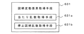
図柄変動要素取得手段631は、図5に示すように、画像表示装置20に表示する図柄又は図柄を決定するための要素(例えば、当たり乱数、停止図柄乱数)を取得するためのものであり、当たり乱数取得手段(抽選手段)631aと、停止図柄乱数取得手段631bと、を備えている。
【0029】
これらの乱数取得手段のうち、当たり乱数取得手段631aは、大当たりを発生させるか否かを決定するための乱数(以下、「当たり乱数」と称する)を取得するためのものである。例えば、ハードウエアのインクリメントカウンタによって生成された0〜65535(65536通り)の乱数を上述した始動口入賞検出装置12aからの入賞信号に基づいて取得している。
【0030】
また、停止図柄乱数取得手段631bは、画像表示装置20に停止表示させる図柄を決定するための乱数(以下、「停止図柄乱数」と称する)を取得するためのものである。
【0031】
続いて保留球情報記憶手段632は、画像制御手段635による画像の変動表示中に始動入賞口12へ入賞した(すなわち、始動口入賞検出装置12aにより検出された)遊技球の入賞情報を、入賞した遊技球に対応させて、所定上限個分(本実施例では4個分)記憶するためのものである。なお、本実施例では、入賞情報として、当たり乱数、停止図柄乱数、保留球数等が記憶されている。また、本実施例においては記憶可能な保留球数の上限値を4個としたが、これに限定されるものではなく適宜変更可能である。このような保留球情報記憶手段632に、保留球の入賞情報が所定上限個分記憶されている場合は、それ以上の遊技球が始動入賞口12に入賞しても、その遊技球に対する入賞情報は記憶されず無効となる。すなわち、図柄変動中において始動入賞口12を通過する4個の遊技球に対して取得された情報は記憶することができるが、5個目以降の遊技球は始動入賞口12を通過しても無視されて賞球のみ払い出しが行われるようになっている。尚、保留球情報は図1、2のように保留球ランプ25に示され、保留球数に対応する個数の保留球ランプ25が点灯する。
【0032】
また、当たり乱数判定手段633は、当たり乱数に応じて特別遊技を行うか否か、すなわち大当たりか否かを判定するためのものである。例えば、ROMに記憶された当たり値「0〜200」と先の当たり乱数として取得された乱数値(0〜65535のうちの1つ)とを比較し、この乱数値が当たり値「0〜200」である場合に「当たり」と判定する。なお、後述する確率変動中には、遊技設定手段80により、例えば(当たり画像が確変画像の場合)当たり値が上記「0〜1280」に設定され、当たり確率を高確率に変動している。
【0033】
また、画像変動決定手段(演出制御手段)634は、特別遊技を実行させるにあたって遊技者へ「当たり」への期待、興奮を維持せしめるために画像表示装置20にて行う種々の演出を決定し制御するための手段であり、予め定められた複数の演出から1つの演出を抽選し、決定する変動パターン決定手段(特定遊技演出決定手段)634aと、遊技者の入力に応じて発信される操作信号を出力する操作信号出力手段634bと、実行される特定遊技に応じて予め設定されたタイミングと遊技者の操作手段23へのアクセスタイミングとが合致するかを判定する操作判定手段634cと、操作判定手段634cの判定結果に対応する特定遊技の結果演出を決定する特定遊技結果演出決定手段634dと、該特定遊技結果演出決定手段634dで決定された結果演出が前記当たり乱数判定手段633と合致するような付加演出を決定する特定演出逆転結果演出決定手段634eとを備えている。
【0034】
変動パターン決定手段634aは、図6に示すように表示変動態様決定手段6341と、可動役物作動態様決定手段6342と、画像加工態様決定手段6343とを備えている。
【0035】
表示変動態様決定手段6341では、各図柄変動過程それぞれにおいて表示装置20に表示する予め定められた複数の演出のパターンから1つを決定する。ここで、変動表示態様とは、表示装置において複数の画像を連続して表示するためのデータを意味し、このデータにもとづいて後述の画像制御手段635、作動制御手段636、ランプ制御手段637が実行されるものである。詳細には後述するが概ね抽選により特定演出(スイッチ装置23を操作するためにスコープ28を作動させる演出)を実行するか否かを決定し、特定演出を実行しない場合には「通常変動パターンテーブル」から、特定演出を実行する場合には「特定変動パターンテーブル」から変動態様を決定する。さらに、ここでの決定は前述の当たり乱数判定手段633により判定された「当たり」「ハズレ」も決定要素として付加される。
【0036】
ここで図7、8を参照して表示変動態様決定について具体的に説明する。図7は、「通常変動パターンテーブル」の一例を、図8は「特定変動パターンテーブル」の一例を示している。上述するように始動入賞口12に遊技球が入賞すれば、その入賞により「当たり」か否か抽選し、その抽選結果を判定する。具体的には取得当たり乱数値を当たり乱数判定手段633により判定する。次に、表示装置20で表示する演出について特定演出にするか通常演出にするかを抽選等で決定する。この決定により特定演出が実行されない場合には、図7に示すような予め設定された「通常変動パターンテーブル」の表示変動態様D〜Fのうちから決定し、さらに決定された表示変動態様D〜Fは上述する「当たり」「ハズレ」判定にもとづいて2つの態様に分けられ、最終的には6つの表示変動態様D1、D2、E1、E2、F1、F2のうち1つの態様が決定される。また、特定演出が実行される場合には、図8に示すような予め設定された「特定変動パターンテーブル」の表示変動態様A〜Cのうちから決定し、さらに決定された表示変動態様A〜Cは上述する「当たり」「ハズレ」判定にもとづいて2つの態様に分けられ、最終的には6つの表示変動態様A1、A2、B1、B2、C1、C2のうち1つの態様が決定される。
【0037】
ここで特定演出について図9〜14を参照して概説する。図9は、表示装置20に表示された特定演出時の特定変動表示態様の一例を示している。特定演出が実行されると図9に示すように表示装置20には背景画像201の中に変動表示されるオブジェクト画像(図柄)202が表示される。このオブジェクト画像202は上述するように「特定変動パターンテーブル」から決定され、ここではオブジェクト画像としてダチョウが示されている。本実施形態で例示する特定演出では遊技者が操作手段としてのスイッチ装置13を押圧することにより拿捕できるというものである。この拿捕の際にダチョウへの照準を遊技者に提供するために可動役物としてのスコープ28を表示装置20の前面に出現する。このスコープ28が出現したイメージを略示したものが図10である。また、スコープ28は左右に滑動作動する物理的要素であり、枠28a内の表示内容を視認できるように枠28a内の領域28bは空白又は透明体で占有されている。なお、本実施形態ではスコープ28は物理的要素として構成されているが、後述する背景画像201の画像加工によりスコープ28として遊技者が認識可能な画像加工処理を行う場合は物理的要素を使用するまでもなくスコープ28を遊技者に提供できることも考えられる(但し、本実施形態では、物理的要素としてのスコープ28が介在することを前提として述べる)。実際には、このスコープ28をダチョウへの照準として遊技者に認識させ得るため、物理的なスコープ28と、表示装置20で表示される特定遊技の画像201、202と、を重ね合わせることに加え、スコープ28の照準としての視的効果を向上せしめるために枠内を明るくする(又は暗くしても良い)特定遊技画像の処理203、204を施している(図11参照)。尚、図11を参照すれば、現実には重ね合わせられているスコープ28、特定遊技画像201、202と、特定遊技画像の処理用画像203、204とをずらして示している。
【0038】
このように演出された特定遊技状態で、遊技者は左右に滑動するスコープ28の照準位置28dがダチョウと合致したときにスイッチ装置23を操作する。そして、合致したときにタイミングよく操作すればダチョウ拿捕成功となり、合致しないときにスイッチ装置23を操作するとダチョウ拿捕失敗となる。そして、遊技者にとってダチョウの拿捕成功をもって遊技機が「大当たり」の遊技状態、すなわち特別遊技状態になると認識させている。
【0039】
しかしながら、パチンコ機等では始動入賞口12への入賞時に予め「大当たり」するか否か抽選されているものであり、本実施形態においても同様である(後述参照)。この点、遊技者の操作と表示器20での表示画像内容とに差異が生じることないようにする必要があり、操作判定手段634cにより判断される。また、遊技者は特定演出中に複数回特定遊技を実行することができる。各特定遊技ではそれぞれ拿捕すべきダチョウが現れ、遊技者は予め定められた弾数(「スイッチ有効回数」と称す)の範囲内でダチョウ拿捕への挑戦が可能となる。この特定演出で実行される特定遊技回数及び各特定遊技中に遊技者が挑戦できるスイッチ有効回数ともに該上記表示態様変動態様が決定される際に同時に決定され(図8参照)、スイッチ有効回数については遊技者に視認させるべくランプ制御手段637(図4参照)によりリボルバ・ランプ31の同数のランプを各特定遊技毎に点灯させる。また、ランプ制御手段637は遊技者がダチョウ拿捕挑戦する度、すなわちスイッチ装置23を操作するたびに点灯されたランプを1つ消灯させるように制御する。さらに、各特定遊技において遊技中の遊技者の操作回数がスイッチ有効回数を超えた場合又は所定時間経過し遊技終了した場合はスイッチ装置23からの出力を無効にし、且つ新たな特定遊技が開始されるとスイッチ装置23を再び有効化する必要がある。本実施形態では、これを操作信号出力手段634cで制御している。なお、本実施形態の特定演出中の特定遊技は最大3回とされている。
【0040】
次に、上述する遊技者の操作と表示装置20での表示画像内容とに差異が生じることないようにすることについて説明する。パチンコ機では当たり乱数判定手段633において「当たり」と判定されたことをもって「大当たり」すなわち特別遊技状態へ移行するが、遊技者のスイッチ装置23入力のタイミングが悪く本来、ダチョウを拿捕できないような場合でも特別遊技へは移行することとなる。この場合に、表示装置20で示す画像を「当たり」判定結果と合致させ、ダチョウを拿捕したがごとき画像(以下、「成功画像」と称す)を表示すると遊技者にとってスイッチ装置20によるダチョウ拿捕の演出は結局、「大当たり」には何の関係もないものと認識され、遊技機の演出性が損なわれることとなる。従って、遊技者がスコープ28の照準Aとダチョウが合致したタイミングでスイッチ装置23を入力しなければ入力失敗となり、表示される画像もこれに対応する失敗画像とし、逆にタイミングよく入力した場合には成功画像が表示されることとし、図4に示す特定遊技結果演出手段634dにより決定された画像を画像制御手段635で実行する。ここで問題となるのは当たり乱数値が「当たり」にもかかわらず遊技者が特定遊技のいずれかで入力失敗し失敗画像が表示された場合と、逆に「ハズレ」にもかかわらず遊技者が特定遊技全てで入力成功し成功画像が表示された場合である。これらの「ずれ」が生じた場合には各特定遊技が終了した後に、特定演出逆転結果演出手段634eにより決定された画像を追加表示するように画像制御手段635を実行し、「ずれ」を解消しても納得できる演出(特定演出逆転結果演出)を遊技者に提供する。図12を参照すれば「当たり」にもかかわらず特定遊技のいずれかにおいて遊技者が入力失敗したときの特定演出逆転結果演出が実行された場合に追加される画像の一例である。ここではダチョウ拿捕失敗画像(例示せず)が表示された後でライオンが登場し、遊技者の代わりにダチョウ拿捕をサポートしてくれる内容の画像が提供されている。
【0041】
以上を前提として特定演出の具体的方法について説明する。再び図8を参照すれば「特定変動パターンテーブル」には図7に示す「通常変動パターンテーブル」において説明した要素に加え、表示変動態様(特定遊技)の決定に伴い決定される要素として、「照準位置対応カウンタ値(H)」と、「特定遊技実行カウンタ値(T)」と、「照準値(キャラクター数)(C)」と、「スイッチ有効回数(N)」と、「スイッチが有効になるカウント値(M)」とが付与されている。まず、「照準位置対応カウンタ値(H)」とは、遊技者がスイッチ装置23を操作したとき有効となるかを操作信号出力手段634bで判断するために使用する。すなわち、スイッチが押されるタイミングと照準となるキャラクタ位置(オブジェクト画像)とが合致しているか否かを判断する基準として使用されるものである。また、「特定遊技実行カウンタ値(T)」とは、特定遊技を実行する時間(開始から終了まで)をカウンタ値で示したものであり、画像制御手段が特定遊技を終了するか否かを判断するために使用する。「照準値(C)」とは、特定遊技演出実行時に表示装置に表示されるオブジェクト数(キャラクタ数:本実施形態ではダチョウの数)を示し、遊技者が可動役物(スコープ)28の一部分(照準28d)とオブジェクトが重なったときにスイッチ操作させるために表示される。「スイッチ有効回数(N)」とは、1回の特定遊技実行中に、何回遊技者がスイッチを操作することができるかの上限数を示している(上限数を超えた場合は、スイッチの操作は無効となる)。さらに、「スイッチが有効になるカウント値(M)」とは、各特定遊技毎にそれぞれ設定した表示変動態様において設定されているスイッチが有効となるカウンタ値を示している。また、特定遊技が何回目の実行であるかは「S」で表示し、例えば1回目の特定遊技の場合はS1又はS=1と表示する。ここでカウンタ値とは、特定遊技の開始から終了までの期間に設定されている、所定の区切りタイミングにて区切られている値をいう。この区切りは、所定時間(例えば、1秒、2秒毎等)や所定の演出出力タイミング(1画像出力毎等)により区切られる。
【0042】
以上の要素に基づいて作成された特定演出実行時におけるタイムチャートを例示した図13を参照する。この図では特定演出中に特定遊技として図8の表示変動態様A、Bが順に実行され、最後に特定演出の結果演出(逆転演出も含む)が実行される様子を示している。このように上述するカウンタ値等の要素を定め、読み込むことで表示態様が決定され、特定演出を時系列的に系統化することができ、特定演出の制御を実行することができる。なお、具体的には、本実施形態では図13に示すとおり特定演出実行前に、2カウント目に「特定演出の実行選択演出」は実行され、実行中は遊技者が所定演出を実行するか否かを選択することができる(図示せず)。このときスイッチ装置23により実行選択がされる又は所定時間(2カウント)経過すると、スイッチが非有効化される。実際の制御方法については後述する。
【0043】
また、表示変動態様が決定され、特定演出が実行される場合は可動役物作動態様決定手段6342が実行され、特定演出時にスコープ等の可動役物28が作動するパターンが表示変動態様に対応して決定されるが(カウンタ値「H」参照)、可動役物28の動作と特定遊技における画像との連関性をもたせる必要がある。すなわち、決定された表示変動態様にもとづいて表示装置20に表示される画像を加工する態様を画像加工態様決定手段6343により決定する。具体的には、図11に示すようにスコープ28の枠内が明るい領域204とし、可動役物(スコープ等)28の枠外を暗い領域203とするように画像処理がなされる。
【0044】
以上、特別遊技移行判定手段について概説してきたが、次に、特別遊技を実行する手段70について説明する。特別遊技実行手段70は当たり乱数判定手段633により当たりと判定された場合に特別遊技を実行するためのものであり、単位遊技実行手段71と、継続判定手段72と、確変遊技移行判定手段73とを備えている(図4参照)。
【0045】
単位遊技実行手段71は、特別遊技中における単位遊技を行うためのものであり、大入賞口駆動手段711と、単位遊技終了判定手段712とを備えている。
【0046】
大入賞口駆動手段711は、大入賞口13を開放して遊技球の入賞を容易にするように大入賞口駆動装置13mを作動させるためのものである。
【0047】
単位遊技終了判定手段712は、予め設定された単位遊技終了条件に基づいて、単位遊技を終了させるか否かを判定するためのものである。
【0048】
継続判定手段72は、予め設定された継続条件に基づいて、特別遊技を終了させるか否かを判定するためのものである。
【0049】
確変遊技移行判定手段73は、特別遊技終了後に遊技者にとって有利な確変遊技を実行するか否かを判定するためのものである。遊技設定手段80は、確変遊技移行判定手段73によりその判定結果が肯定的、すなわち確率画像であると判定された場合には、当該特別遊技終了後の遊技が通常遊技よりも遊技者に有利となる確変遊技となるように設定するためのものである。例えば、確率抽選テーブルをセットして、当たり乱数判定手段624によって参照する当たり値を「0〜200」から「0〜1280」にその数を増やして、当該特別遊技終了後の当たり乱数が当たりとなる大当たり確率を通常よりも高確率になるように設定している。
【0050】
また、遊技設定手段80は、確変遊技移行判定手段73によりその判定結果が否定的であると判定された場合には、当該特別遊技終了後の遊技が、通常遊技に設定されるためのものでもある。なお、払出制御手段90は、賞球払出装置45から賞球を払い出させる制御を行うためのものである。
【0051】
次に、本実施形態における制御概要を図14〜図25に示すフローチャートを参照しながら説明する。
【0052】
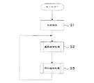
図14は、このパチンコ機のメインフローチャートである。遊技制御手段50は、まずステップS1で遊技機全体の初期設定を行った後、ステップS2の通常遊技処理、ステップS3の特別遊技処理を行った後、ステップS2に戻る。この動作は電源が遮断されるまで繰り返し実行される。
【0053】
図15は通常遊技処理S2のフローチャートである。通常遊技処理S2は、入賞口への入賞をチェックする入賞口入賞チェック処理(ステップS20)と、特別遊技を移行するか否かを判定する特別遊技移行判定処理(ステップS22)とを実行した後、本処理を終了する。
【0054】
図16は、入賞口入賞チェック処理S20のフローチャートである。入賞口入賞チェック処理S20は、まず、遊技球がいずれかの一般入賞口11への入賞が一般入賞口入賞検出装置11aにより検出されると(ステップS201)、その検出信号は遊技制御手段50に送られて、一般入賞フラグがセットされる(ステップS202)。そして、このフラグに基づいて払出制御手段90により賞球払出装置45に作動信号が出力され、この信号を受けて賞球払出装置45が作動して、各入賞球に対して所定数(例えば、10球)の賞球を賞球払出装置45から球受け皿に払い出す。なお、ここでセットされたフラグは、賞球動作に基づいて適宜リセットされる。また、始動入賞口12への遊技球の入賞が始動口入賞検出装置12aにより検出されると(ステップS205)、その検出信号は遊技制御手段50に送られ、始動入賞フラグがセットされる(ステップS206)。そして、このフラグに基づいて払出制御手段90により賞球払出装置45に作動信号が出力され、この信号を受けて、賞球払出装置45が作動して始動入賞口12への入賞球に対して所定数(例えば、5球)の賞球を賞球払出装置45から球受け皿に払い出す。
【0055】
次に、特別遊技移行判定処理S22を実行する。図17は特別遊技移行判定処理S22の前段フローチャート、図18は図柄変動要素取得処理S230のフローチャート、図19は図柄変動処理S250のフローチャート、図20は変動パターン決定処理S251のフローチャート、図21は変動パターン決定S254のフローチャートである。
【0056】
特別遊技移行判定処理S22は、まず、図柄変動要素取得処理S230を行う。図柄要素取得処理S230は、始動入賞口12に入賞したか否かを確認するために始動入賞フラグがオンであるか否かを判定する(ステップS231)。オンでない場合はこの処理を終了し、オンである場合は始動入賞フラグをオフする(ステップS232)。次に、記憶されている始動入賞口12へ入賞した保留球の数が記憶上限個(例えば、4個)に達しているかどうか、すなわち保留球数記憶手段632に入賞情報を記憶することができるか否かを確認する(ステップS233)。ここで、保留数の数が記憶上限個に達しておらず記憶が可能である場合は、当たり乱数取得手段631aにより当たり乱数を取得し(ステップS235)、停止図柄乱数取得手段631bにより停止図柄乱数を取得し(ステップS236)、これら入賞情報を各保留球の数n(n=1,2,3,4)に対応して保留球情報記憶手段632に設けられている乱数値エリアへ格納し(ステップS237)、この処理を終了する。なお、ステップS233において、保留球の数が上限個に達している場合は、この図柄変動要素取得処理S230を終了する。
【0057】
続いて、特別遊技移行判断処理S22は、図17に示すように、上述する保留球の記憶があるか否かの確認を行う(ステップS240)。ここで、保留球の記憶がない場合には本処理を終了し、保留球の記憶がある場合には、保留球の数n=1に対応して保留球情報記憶手段632の乱数値エリアに格納されている情報を読み出す(ステップS241)。次に、保留球情報記憶手段632の乱数値エリアに格納されている乱数値をシフトする(ステップS242)。ここで、保留球情報記憶手段632における乱数値のシフトの方法について概説する。ステップS241では、保留球情報記憶手段632において、図26(a)で示すように、保留球の数n=1に対応する乱数値Aを読み出す。そして、次のステップS242では、図26(b)に示すように保留球の数n=2,3,4に対応する乱数値エリアに格納されている乱数値B,C,Dを、保留球の数n−1に対応する乱数値エリアにシフトして格納する。
【0058】
次に、演出決定手段により図柄変動処理が実行される(ステップS250)。この図柄変動処理S250について図19を参照しつつ以下、説明する。
【0059】
まず、図柄変動パターン決定処理が実行される(ステップS251)。図柄変動パターン実行処理S251は図20に示すようにまずステップS241で読み込まれた乱数値のうち当たり乱数を読み込み(ステップS252)、読み込まれた当たり乱数の抽選結果、すなわち「当たり」又は「ハズレ」を判定する(ステップS253)。具体的には前述するように例えば0〜65534の乱数のうち、0〜200に当たり乱数が該当する場合に「当たり」とする。この抽選結果に基づいて変動パターン決定する(ステップ254)。
【0060】
変動パターン決定S254は、図21に示すようにまず表示変動態様決定処理が実行される(ステップS254a)。この処理S254aは、始動入賞口12に遊技球が入賞した際に表示装置20で実行する演出を決定するステップである。具体的には、特定演出を実行するか通常演出を実行するかを抽選等により決定する。そして、該決定の結果、特定演出を実行しない、すなわち通常演出を実行する場合には前述の「通常変動パターンテーブル」から、又特定演出を実行する場合には「特定変動パターンテーブル」から表示態様を抽選等により決定する(ステップS254a)。前述するように図7、8を参照すれば、変動パターンテーブルの一例が示されている。図7は通常変動パターンテーブルの例示であり、表示変動態様D、E、Fが示されている。また、図8は特定変動パターンテーブルの例示であり、表示変動態様A,B、Cが示されている。
【0061】
次に、決定した表示変動態様情報を画像制御手段635に送信する(ステップS254b)。そして、ステップS254aで決定された表示変動態様が特定演出を実行するか否かを判定し(ステップS254c)、特定演出を実行する場合は特定演出中に実行される特定遊技の回数「S」を読み込む(ステップ254d)。本実施形態では特定遊技の最大実行回数を3回に定めている(1≦S≦3)。なお、特定遊技の1回目、2回目、3回目をそれぞれS1、S2、S3と規定する。次に、特定遊技毎に表示照準位置対応カウンタ値を読み込む(ステップS254e)。ここでは、S1=X1、S2=X2、S3=X3 とする。そして、特定遊技毎に「(可動役物)作動パターンテーブル(図示せず)から可動役物作動態様を決定し(ステップS254f)、役物照準位置(図13参照)対応カウンタ値を読み込んだ後(ステップS254g)、前述の照準位置対応カウンタ値と役物照準位置対応カウンタ値とが合致するカウンタ値を「H」として設定する(ステップS254h)。そして、特定遊技毎に特定遊技パターンテーブルから選択された態様に設定されている特定演出実行カウンタ値「T」を読み込む(ステップS254i)。ここではS1=T1、S2=T2、S3=T3、とする。次に、特定遊技毎に特定遊技パターンテーブルから選択された態様に設定されている照準値すなわちオブジェクト画像として表示されるキャラクタ数「C」を読み込む(ステップS254j)。ここでは、S1=C1、S2=C2、S3=C3、とする。次に、特定遊技毎に特定遊技パターンテーブルから選択された態様に設定されているスイッチ有効回数「N」を読み込む(ステップS254k)。ここでは、S1=N1、S2=N2、S3=N3、とする。さらに、特定遊技毎に特定遊技パターンテーブルから選択された態様に設定されているスイッチが有効となるカウンタ値「M」を読み込む(ステップS254l)。S1=M1、S2=M2、S3=M3、とする。以上により変動パターンが決定される(ステップS254)。なお、ステップS254cにおいて特定演出を実行しない場合には、決定した「通常変動パターンテーブル(図7参照)」から選択決定した変動態様を実行(通常変動演出の実行)を行い(ステップS277、S278、S279)、図柄変動処理S250が終了する(図19参照)。
【0062】
再び図19を参照すれば、変動パターン決定処理S251がなされると、選択画面が表示され(ステップS255)、選択演出が実行され(ステップS256)、スイッチ装置23が有効化される(ステップS257)。これは、特定演出を実行するか否か遊技者がスイッチ装置(操作手段)23の入力を通じて選択できるようにするための工程である。本実施形態では図13に示すようにスイッチ装置23を有効にするか否かの選択は2カウント目までに制限されており、特定演出を実行すると遊技者が選択した場合(ステップS258)には、スイッチ装置23が非有効化される(ステップS259)。特定演出中の各特定遊技を実行できるようにするために一端スイッチ入力をリセットする必要があるからである。なお、特定演出実行を遊者が拒んだ又は所定時間が経過した場合には、表示変動態様が再度から決定、実行され、その終了をもって図柄変動処理が終了する(ステップS275〜279)。
【0063】
特定演出実行が選択され(ステップS258)、スイッチ装置が非有効化されると(ステップS259)、図13のタイムチャートに示すように特定遊技におけるカウントが開始され(ステップS280)、変動パターン決定処理S251において読み込まれた各カウント値等の要素情報が画像制御手段635等に送信される(ステップS260)。これにより特定遊技が開始される(ステップS261)。
【0064】
特定遊技が開始され、開始(特定演出の実行選択演出カウンタ値が2カウントのときを0カウントとする:図13参照)からのカウント(時間)が非有効化されたスイッチ装置23が有効となるカウンタ値「M」(S1=M1)まで経過するとスイッチ装置23が有効化される(ステップS262、S263)。その後、スイッチ装置を遊技者が操作すると該操作情報が送信され(ステップS264、S265)、各特定遊技毎に入力可能なスイッチ有効回数「N」の値が1つ減じられ、「N」=0となった場合にはスイッチ装置23が非有効化される(ステップS266〜S268)。そして、特定遊技の実行が可能な所定時間(カウンタ値「T1」)経過(S1=T1)するまでは、ステップS264〜268までが繰り返される(ステップ269)。上記所定時間経過(S1=T1)した後は、該情報が送信され(ステップS270)、スイッチ装置23が既にステップS268で非有効化されている場合には各特定遊技の残存回数を1回減じ(ステップS273)、スイッチ装置23が未だ非有効化されていない場合には非有効化し(ステップS272)、各特定遊技の残存回数を1回減じ(ステップS273)、次の特定遊技S2に移行する。以上のステップS280、S260〜273の工程は、各特定遊技の残存回数がゼロになるまで繰り返され(ステップS274)、実行可能な特定遊技の残存回数がゼロになる、すなわち全ての特定遊技が終了したときには変動態様実行が終了し図柄変動処理S250が終了する(ステップS279)。
【0065】
ここで画像制御手段635における画像の制御方法について説明する。図25を参照すれば、特定演出中の画像制御に関するフローチャートが示されている。まず、画像制御手段635はステップS251(図19参照)により決定された表示態様情報を受信すると(ステップS401)、決定された該情報を読み込む(ステップS402)。そして、該情報により特定演出が実行されるか否か判定され(ステップS403)、実行される場合には、特定画像処理情報を図示しない画像メモリから読み込み所定の格納エリアに格納する(ステップS404)。なお、ステップS403で特定演出を実行しない場合には、通常演出画像情報を図示しない画像メモリから読み込み、通常演出における画像表示が画像制御手段635で実行され、画像表示制御が開始され(ステップS425)、通常演出が終了をもって画像制御過程が終了する(ステップS426)。
【0066】
上記特定画像制御を実行する場合であって該画像処理情報を格納した後、ステップS260(図19参照)で送信されたカウント開始情報が受信されたか否かを判断し(ステップS405)、受信された場合には、画像制御手段635により画像表示制御が開始され(ステップS406)、特定画像処理ポイントに到達、すなわち特定演出実行選択演出が実行され1回目(S1)の特定遊技が実行されるときのカウント値情報を認識すると(ステップS407)、ステップS404により格納された特定画像処理情報にもとづき特定画像(オブジェクト画像)の処理を実行する(ステップS408)。そして、特定遊技が開始され、ステップS265によるスイッチ操作情報の受信を判断し(ステップS409)、そのスイッチ操作時のカウンタ値がステップS254hで設定された照準位置対応カウンタ値「H」と合致する、すなわちスイッチ装置23の入力タイミングが照準となるキャラクタ(オブジェクト画像)の位置と合致するかを判定し(ステップS410)、合致する場合には特定遊技の残存回数が1回か否か(最後の1回か)判定する(ステップS413)。この判定により、残存回数が1回(ここではS=1と表記する)でない場合又は残存回数が1回であって照準値すなわち該特定遊技で表示されるキャラクタ数「C」が1(C=1)の場合には、実行中の変動態様が当たり変動態様か否か(図8参照)判断し(ステップS415)、「当たり」の場合には成功演出画像を表示装置20の背景画像に差込み(ステップS416)、「ハズレ」の場合には失敗演出画像を表示装置20の背景画像に差込む(ステップS412)。また、特定遊技の残存回数が1回の場合に「C」が1(C=1)でない場合にも、成功演出画像を表示装置20の背景画像に差込む(ステップS416)。さらに、スイッチ操作時のカウンタ値がステップS254hで設定された照準位置対応カウンタ値「H」と合致しない場合には、失敗画像が表示装置20の演出画像に差し込まれる(ステップS412)。
【0067】
そして、ステップS270により送信されたカウンタ値がT1に到達した情報を受信するまで(特定遊技が終了するまで)上記ステップS409〜416までのステップを繰り返し、カウンタ値がT1となった情報を受信したかを判断し(ステップS417)、ステップS273、S274によりS=0、すなわち実行された遊技が特定演出における最後の特定遊技であったと認識されるまで、ステップS409〜S418を繰り返し、次の特定遊技へ移行する。最後の特定遊技が終了(S=0)すると、実行中の変動態様がハズレ変動態様である場合には特定演出全体での遊技者の遊技が失敗であったことを表示すべく特定演出(逆転)結果演出決定手段S634eにより決定された特定演出(失敗)結果演出を出力し(ステップS419〜423)、画像制御が終了する。また、当たり変動態様である場合、既に失敗演出画像が差込まれている(ステップS412)場合、「当たり」判定と演出画像との矛盾を覆す演出をすべく特定演出逆転結果演出を画像制御手段635に出力した後(ステップS421)、特定演出成功の結果演出を実行し、画像制御は終了する。また、失敗演出画像が差込まれていない、すなわちステップS416で成功演出画像が差込まれた場合にはそのまま特定演出成功の結果演出を実行し(ステップS422)、画像制御が終了する。
【0068】
再び図17を参照すれば、上述するように画像変動処理S250が実行されると、次にステップS241で読み出した当たり乱数に応じて当たり乱数判定手段633は特別遊技を行うか否か、すなわち大当たりか否かを判定する(ステップS245)。ここで、判定結果が当たりであるときは、特別遊技フラグをオンし(ステップS246)、ステップS241で読み出した情報を消去し(ステップS247)、特別遊技移行判定処理S22を終了する。また、ステップS245において、判定結果が外れであるときは、特別遊技フラグをオンせずにそのままステップS247に進み、特別遊技移行判定処理S22を終了する。
【0069】
次に、特別遊技処理S3を行う。この特別遊技処理S3は、取得した当たり乱数の抽選結果が当たりのとき、単位遊技を所定回数(例えば15回)だけ実行可能な特別遊技を成立させる処理である。図22は、特別遊技処理S3の前段フローチャート、図23は特別遊技処理S3の後段フローチャート、図24は特別遊技終了処理S320のフローチャートである。
【0070】
まず、特別遊技フラグがオンであるか否かを確認する、すなわち取得した当たり乱数が当たりであったか否かを確認し(ステップS301)、外れであればこの処理を終了する。当たりの場合は、例えば特別遊技フラグをオフしたり、大当たり確率が高確率の確変遊技であった場合は通常の低確率に変動させて確変遊技を終了させる等の特別遊技初期設定を行う(ステップS302)。次に、単位遊技を行うための各種の初期設定を行い(ステップS303)、単位遊技を開始する。
【0071】
単位遊技は、大入賞口駆動手段711により大入賞口駆動装置13mを作動させて大入賞口13を開放して、第1回目の単位遊技を開始する。大入賞口13が開放されると、遊技領域空間を落下移動する遊技球は大入賞口13に非常に入賞し易い状態となる。このような状態で大入賞口13に遊技球が入賞すると、払出制御手段90によりこの入賞球に対して所定の数(例えば、13個)の賞球が球受け皿に払い出される。
【0072】
このようにして第1回目の単位遊技が開始されると、単位遊技終了判定手段712により、以下に述べるような単位遊技終了条件の達成の有無が判断され、この単位遊技終了条件が達成されるまでは大入賞口13の開放作動が継続される。
【0073】
単位遊技終了条件は、「入賞球数」及び「制限時間」を用件として設定されている。まず、「入賞球数」の用件は、大入賞口13に入賞したトータルの遊技球の数が所定数(例えば、10球)に達した時点で単位遊技終了条件が達成されたと判断するというものであり、図23に示すように、大入賞口入賞検出装置13aにより大入賞口13に入賞したかを判断する(ステップS304)。入賞した場合は、大入賞口13に取り付けられている入賞球のカウンタ(図示せず)から予め設定されている単位遊技条件終了のために必要な入賞球数(例えば、10球)から1を減らす(ステップS305)。また、特定領域通過検出装置13bにより特定領域(図示せず)に遊技球が入賞したか否かを判断し(ステップS306)、入賞した場合は特定領域フラグをセットする(ステップS307)。そして、大入賞口13の入賞球数が所定の数(例えば、10球)に達したか否かを判定し(ステップS308)、入賞球数が所定の数を満たしていた場合は単位遊技終了条件が達成されたためステップS310に進み、入賞球数が所定の数を満たしていない場合は次の単位遊技終了条件であるステップS309に進む。
【0074】
次に、「開放時間」の要件は、単位遊技開始後における大入賞口13の開放時間が予め定められた時間(例えば、30秒)経過したときにこの単位遊技終了条件が達成したと判断されるというものであり、ステップS309では、この終了条件が達成したか否かを判断する。そして、制限時間が終了していない(すなわち、単位遊技終了条件が満たされていない)場合はステップS304へ戻り次の単位遊技を行う。一方、制限時間が終了(すなわち、単位遊技終了条件を満たされた)場合は、ステップS310へ進む。
【0075】
以上のように単位遊技終了判定手段712は、「入賞球数」もしくは「制限時間」の条件のいずれか一方が満たされた時点で、単位遊技終了条件が達成されたと判断し、単位遊技を終了する。
【0076】
上記のような単位遊技終了条件を達成したときは大入賞口13の開放を止め、継続判定手段72により継続判定条件が達成されているかを判断する(ステップS310)。この継続条件とは、単位遊技中に特定領域に遊技球が入賞して特定領域フラグがセットされたか否かという条件であり、単位遊技中に特定領域への入賞があった場合にのみ継続条件が達成されたと判断される。このため、特定領域への入賞がないまま単位遊技が終了した場合には、ステップS310から特別遊技終了処理S320を行う。
【0077】
一方、ステップS310において継続条件が成立したと判断された(すなわち、今回の単位遊技中に特定領域へ少なくとも1つの入賞球があった)場合には、特定領域フラグをクリアする(ステップS311)。今回の特別遊技を開始した後における単位遊技のラウンド数を数えるためにカウンタがあり、このカウンタには予め所定回数(例えば、15回)がセットされている。このカウンタから1を減らす(ステップS312)。続いて、このラウンド数のカウンタが0未満になったか否か、つまり単位遊技の繰り返し回数が所定回数行われたか否かを判断する(ステップS313)。ここで、ラウンド数のカウンタが0未満ではない、すなわち所定回数繰り返されていない場合は、ステップS303に戻り、次の単位遊技を行う。また、ラウンド数のカウンタが0未満である、すなわち単位遊技が所定回数繰り返された場合は、ステップS313から特別遊技終了処理S320へ進む。
【0078】
特別遊技終了処理S320は、図24に示すように、まず、確変遊技移行判定手段73により、当選時における当たり図柄が確変図柄であるか否かを判定する(ステップS321)。確変図柄であると判断されたときは、各確変当選画面表示(図示せず)がなされ(ステップS322)、遊技設定手段80によって、当たり乱数が当たりとなる確率(すなわち大当たり確率)を通常よりも高確率になるように当たり値が設定されている確変抽選テーブルをセットする。また、確変図柄ではないと判断されたときは、確変非当選画面表示(図示せず)がなされ(ステップS323)、遊技設定手段80によって、通常の当たり確率が再び通常抽選テーブルをセットする。
【0079】
最後に、画像表示装置20を有する中央役物15に配置されたスコープ等の可動体28の運動について言及する。図27を参照すれば、スコープ28が画像表示装置20上を横方向に滑動する様子を略示している。スコープ28は非作動時にはリボルバ30の背後に設けられた格納スペース(図示せず)に収容されている。図27によれば、スコープ28が右端に移動した状態(参照番号28´)においてリボルバ30と重複しているように示されているが、これは非作動時のスコープ28がリボルバ30に設けられた格納スペースに収容された状態を示したものであり、外部からは図2に示すようにリボルバ30表面(リボルバ・ランプ31等を含む)のみが視認され、スコープ28は完全に隠された状態を形成する。これにより、可動体28は作動時、すなわち特定演出時のみ表示装置20(特にその表示画面)上に出てくることとなり、遊技者は可動体28がリボルバ30の背後から出てきたことにより自己操作への準備に対する緊張感が高まり、遊技機への興味を増加させることとなる。
【0080】
また、図示しないが表示装置20の表面に透過性を有する保護フィルムを設け、スコープ28を保護フィルムと表示画面との間で滑動させることが好ましい。保護フィルムを表示画面上に設けることにより遊技球による画面損傷を防止することができる。さらに、保護フィルムの存在によりスコープ28の滑動領域を遊技球の進路から離間することができ、その結果、スコープ28が特定演出時に作動することにより該スコープ28が遊技球を弾き飛ばし、遊技球の入賞口への進行の障害となることを回避することができる。従って、遊技者は入賞口へ狙って発射された遊技球がスコープ28により邪魔され不快感を得ることはなく、スコープ28滑動による演出効果を十分に発揮させることが可能となる。さらに、スコープ28が完全に遊技球進路外に配置されるためにスコープを表示画面の全領域に亘って滑動させることができ、従来の可動体(可動役物)よりも大きな作動領域を確保することができる。
【0081】
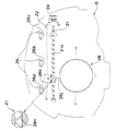
次に、スコープ28の滑動方法について説明する。図28は、スコープ28及びこれを駆動する手段を実線で示し、表示装置を覆う中央役物15を破線で示している。スコープ28はその上部に支持端部28jを有し、この端部28jに横方向の力を付与することにより滑動させる構成をなしている。具体的には、表示装置20の表示画面上方に螺旋状の溝21aが横方向に付与されたスパイラル軸21が軸回り回転自在に設けられており、該スパイラル軸21はスコープ28の滑動方向に平行に配置されている。また、スパイラル軸21に平行に補助軸22が付与されている。スコープ28の端部28jは上記両軸21、22がガイドとなってスコープ28を横方向に滑動させることができる。このときスパイラル軸21の溝21aに端部28jに付与された突起28hを嵌合させる。従って、スパイラル軸21を回転させると螺旋状の突起28hを介して溝21a方向、ひいてはスコープ28を横方向に滑動させることができ、補助軸22によりスコープ28がずれる又は回転することを回避することができる。また、スパイラル軸21jはモータ24により正逆回転可能である。
【0082】
さらに、補助軸22の上方には表示画面すなわちスパイラル軸21と補助軸22とに対して平行に整列配置された3つの位置検出センサ26を設けている。このセンサ26は図28に示すようにそれぞれセンサ突起26a、b、chが付与され、この突起26a、b、cによりスコープ28の最上端に設けられた突起28hが通過することを検出する。図28に示す例によれば、位置検出センサ26は3つ設けられ、左から順に、スコープ28が表示画面の左端に位置するとき、スコープ28が画面中央に位置するとき、スコープ28がリボルバ30背後の格納スペース内に収容されているとき、を検出する役割を有する。この3つのセンサ26を介してモータ24の駆動を制御すれば、スコープ28は画面左端、画面中央、格納スペース内の3箇所を相互間を滑動及び停止させることが可能となる。従って、センサ26をさらに付与すれば、より複雑なスコープ28滑動をもモータの正逆回転のみで制御することが可能となる。
【0083】
以上が本発明の遊技機の実施形態の主たる構成であるが、本発明の遊技機は、上記実施形態に限定されるものではなく、本発明の概念及び精神を逸脱しない種々の実施形態が存在することが当業者にとって明白であろう。
【0084】
【発明の効果】
本発明の遊技機によれば、特別遊技状態(大当たり)への移行に遊技者がスイッチ装置等の操作手段を操作することにより直接参加することが可能となる。従って、遊技機の遊技性を大幅に向上させることができる。詳細には、特定演出中の特定遊技において遊技者が所定タイミングで操作手段を操作することと連動した特定遊技結果演出を表示させ、大当たりへの自己関与を実感させるとともに、現実の「大当たり」移行を司る抽選結果と特定演出結果との不一致が生じた場合には特定演出逆転結果演出を事後的に付与することにより遊技者に演出上矛盾を感じさせないようにすることができる。
【図面の簡単な説明】
【図1】遊技機の正面図である。
【図2】遊技機の中央役物の正面図である。
【図3】可動役物が表示装置に付与された状態の略示図である。
【図4】遊技機の遊技制御手段の構成を示すブロック図である。
【図5】遊技機の図柄変動要素取得手段の構成を示すブロック図である。
【図6】遊技機の変動パターン決定手段(特定遊技演出決定手段)の構成を示すブロック図である。
【図7】遊技機の図柄変動過程で選択される通常変動パターンテーブルである。
【図8】遊技機の図柄変動過程で選択される特定変動パターンテーブルである。
【図9】遊技機の表示装置で表示される特定遊技演出の一例である。
【図10】図9に示す特定遊技中に可動役物が表示装置上に付加された状態を示す図である。
【図11】図10の背景画像、加工画像、可動役物を分離して示した図である。
【図12】図9に示す特定遊技演出における特定遊技演出逆転結果演出を示した図である。
【図13】図8に示す特定変動パターンテーブルに示す変動表示態様A、Bを特定遊技演出実行時におけるタイムチャートの一例を示した図である。
【図14】遊技機の遊技制御手段による制御内容を示すフローチャートである。
【図15】遊技機の遊技制御手段による制御内容を示すフローチャートである。
【図16】遊技機の遊技制御手段による制御内容を示すフローチャートである。
【図17】遊技機の遊技制御手段による制御内容を示すフローチャートである。
【図18】遊技機の遊技制御手段による制御内容を示すフローチャートである。
【図19】遊技機の遊技制御手段による制御内容を示すフローチャートである。
【図20】遊技機の遊技制御手段による制御内容を示すフローチャートである。
【図21】遊技機の遊技制御手段による制御内容を示すフローチャートである。
【図22】遊技機の遊技制御手段による制御内容を示すフローチャートである。
【図23】遊技機の遊技制御手段による制御内容を示すフローチャートである。
【図24】遊技機の遊技制御手段による制御内容を示すフローチャートである。
【図25】遊技機の遊技制御手段による制御内容を示すフローチャートである。
【図26】保留球情報記憶手段における乱数値のシフトの方法について示した図である。
【図27】可動体が画像表示装置上を滑動する様子を示した平面図である。
【図28】可動体の駆動機構の略示図である。
【符号の説明】
20 画像表示装置(表示手段)
23 操作手段
31 リボルバ・ランプ
28 可動役物
50 遊技制御手段
63 特別遊技移行判定手段
70 特別遊技実行手段
633 当たり乱数判定手段
634 画像変動決定手段
634a 変動パターン決定手段(特定遊技演出決定手段)
634b 操作信号出力手段
634c 操作判定手段
634d 特定遊技結果演出決定手段
634e 特定演出逆転結果演出決定手段
635 画像制御手段
637 ランプ制御手段[0001]
BACKGROUND OF THE INVENTION
The present invention relates to a ball game machine represented by a pachinko machine, and a game machine having a fluctuating effect such that a big hit is obtained when an operation means that can be operated by a player is appropriately input.
[0002]
[Prior art]
In conventional gaming machines such as pachinko machines, it is generally known that an image display device using a liquid crystal display or the like is provided at the center of the gaming board constituting the gaming area, and in the start winning opening provided in the gaming area. When the game ball is won, if the symbol (stop symbol) when the symbol is changed after changing the symbol on the image display device is a preset winning symbol, a special gaming state (big hit) is established. It is configured as follows. In this special gaming state, a variable winning opening (large winning opening) provided at the lower part of the gaming area is opened to facilitate the winning of game balls so that the player can acquire a large number of game balls. .
[0003]
By the way, in a pachinko machine, whether or not a special game state is established is determined by a lottery performed at the time of winning a game ball to the start winning opening. On the other hand, a major factor that makes the player feel interesting about the gaming machine is a specific effect until the player actually enters the special game state. In this effect, a game that can make a long transition to the special game state is expected. A machine is required. Normally, various special games are played on an image display device provided in the central part of the game board until a special effect is executed in a gaming machine, and a device is devised for an effect in a process leading to a big hit image (for example, Japanese Patent Application Laid-Open No. 2000-2000) -37519). On the other hand, in the pachislot machine, an operation means (hereinafter also referred to as a switch device) such as a switch that can be directly operated (accessed) by the player can be directly given during the above-mentioned specific performance. A configuration in which a player can select an effect symbol by operating the operating means has been made, but a configuration in which such a player can participate in the effect is also demanded in a pachinko machine.
[0004]
[Patent Document 1] JP 2000-37519 A
[0005]
[Problems to be solved by the invention]
However, in the pachislot machine, the player's switch operation directly affects the outcome of the winning selection as an essential element of the gaming machine, and the above-mentioned player participation method adopted for this is the same as the pachinko machine. Whether or not to win a jackpot can not be diverted as it is to a gaming machine having a structure based on a ball ball winning at a winning opening. Specifically, if a pachislot machine player participation is adopted as it is in a pachinko machine, even if the player can participate in a specific production by operating the switch, it is merely possible to select a production symbol, and it shifts to a special gaming state. The player's operation does not extend to whether or not it is a big hit, and the player simply matches the specific performance design to his / her preference, and the player's switch operation skill and It is irrelevant whether or not the jackpot is the biggest concern of the player. In this sense, a gaming machine such as a pachinko machine could not provide the player with an effect that dramatically increases interest in the gaming machine by directly participating in the effect.
[0006]
The present invention has been made in view of such a problem, and allows a player to participate in a specific effect on a display device executed when shifting to a special gaming state, and for a player to play a gaming machine with his / her own skill. It is an object of the present invention to provide a gaming machine that provides an effect that makes it possible to recognize that a state, that is, a jackpot can be reached.
[0007]
[Means for Solving the Problems]
In order to achieve such an object, in the gaming machine of the present invention, based on the game control means for controlling the progress of the game, the effect control means for executing the effect based on the progress of the game, and the progress of the game by the game control means, A display device for executing display in the symbol variation process from when the symbol is variably displayed until it is stopped, and a player's input operation when a predetermined specific game effect is output to the display device by the effect control means The game control means includes a lottery means for executing a lottery according to a predetermined start condition to determine a win or a lose, and a lottery result when the lottery result is determined to be a win. Has special game execution means for executing a special game advantageous to the player. The effect control means includes operation determination means for determining whether or not a predetermined timing set in advance matches a timing at which the player inputs the operation means. Further, the effects controlled by the effect control means include at least a specific game effect that enables operation by the operation means during the symbol variation display process. The specific game effect includes a predetermined effect mode and its effect mode. An operation matching effect for matching the determination result of the operation determining means and a specific effect reversal result effect for matching the lottery result when the determination result by the operation determining means and the lottery result by the lottery means are different It is configured.
[0008]
In the gaming machine of the present invention, an effect is provided so that the player's operation can be directly involved in the transition to the special gaming state (big win) which is more advantageous to the player than the normal game. First, the player can operate the operation means such as the switch device during the specific game effect displayed in the symbol variation display process displayed on the display device when shifting to the special game state. Is performed at a predetermined timing, an effect that makes a big hit is added. As a result, the player can feel as if the jackpot has been formed by his / her skill, and the gaming performance of the gaming machine can be greatly improved. However, as described above, the transition to the jackpot (special game state) is a lottery when a predetermined start condition such as a winning at the start opening is satisfied, and “winning” or “losing” is determined. This is an essential component of a gaming machine. Therefore, if the result determined by the lottery does not match the player's operation result, that is, if it can be entrusted only to the production according to the player's operation, the “win” or “lost” on the production and the actual “win” or If the game is overlooked, it will be recognized that the player is simply a game machine with a direct effect regardless of his / her own game. It will not be possible to add a great gaming property beyond the machine to the gaming machine. In the gaming machine of the present invention, in order to eliminate such a contradiction, an effect that matches the lottery result is added (inserted) afterwards to solve the above contradiction.
[0009]
The effect control means includes a specific game execution determining means for determining whether or not to execute the specific game effect, and executes the specific game effect when the specific game execution determining means determines to execute the specific game effect. It is preferable to do.
[0010]
Further, the specific game effect can be executed one or more times in one time of the symbol variation display process, and the effect control means further includes a specific game effect number determination means for determining the number of times of executing the specific game effect. The game effect determining means executes the specific game effect based on the specific game effect frequency determined by the specific game effect frequency determining means, and the specific effect reversal result effect is once determined by the specific game effect frequency determining means. Of the above-mentioned specific game effects, it is preferable not to be executed in a specific game effect other than the specific game effect that is executed last.
[0011]
Assuming that the specific game effect can be executed multiple times in the symbol variation display process given at the time of the transition to jackpot, the player's involvement opportunities, which are the characteristics of the gaming machine of the present invention, increase, and the gaming characteristics of the gaming machine It is because it improves more. In this case, the problem is that if there is a different result for each specific game effect (usually in many cases), the entire specific game effect (hereinafter referred to as “specific effect”). It is how to make it consistent with the production results. For example, if the above-mentioned effect that matches the lottery result is added for each specific game effect, an effect that conflicts with the player's operation result is added, and a specific game effect is provided multiple times. Even if it is attempted to improve the game performance, the player will be aware of the fact that his operation is not involved in the jackpot. In the present invention, in consideration of this point, in principle, the player's operation in each specific game effect is matched with the result effect so that the player feels his / her involvement, and the lottery result matches the operation result. The effect is added to the entire specific game effect (specific effect) in the last specific game effect. By doing this, the player can feel the self-involvement in the jackpot, that is, the result of the effect changes according to his / her operation skill except at least the last specific game effect.
[0012]
Further, the effect control means includes an operation number determination means for determining the number of times that the operation means can be operated for each specific game effect, and an operable number display means for allowing the player to visually recognize the operation number determined by the operation number determination means. Further, it is preferable that the operation number determination means subtracts the determined operation number by one and re-determines each time the player operates the operation means.
[0013]
By determining the number of times that the player can operate for each specific game effect a plurality of times, the player can feel that the chance to challenge the jackpot increases. Furthermore, by determining a different operation opportunity (number of operations) for each specific game production, when a specific game with a large number of operations is executed, the player will be in an excited state as if the possibility of winning the jackpot has increased. It becomes. Therefore, in the gaming machine of the present invention, the number of times that the player can operate is determined for each specific game effect, and the number of times that the player can operate is visible so that the player can visually recognize this (see the
[0014]
Further, it is preferable that the operation determination means does not determine an input signal from the operation means at a predetermined time during the specific game effect. That is, a time zone (predetermined time) during which the operation from the operation means is invalidated during the specific game effect is provided. Thereby, the player can operate the operation means only for a predetermined time until the start and end of each specific game effect, and the player is made to recognize that the operation of the operation means is an effect executed only during the specific game effect. In addition, it is possible to make the player recognize the start and end of the specific game when the operation becomes valid when there are a plurality of specific game effects.
[0015]
DETAILED DESCRIPTION OF THE INVENTION
Hereinafter, preferred embodiments of the present invention will be described with reference to the drawings. A pachinko machine as a representative example of the gaming machine in the present invention will be described. As will be described in detail later, in this pachinko machine, an effect is added such as when a player fires a bullet from a pistol and hits a target, and the player can participate in the effect. Yes.
[0016]
First, the configuration of the main elements of the pachinko machine will be described. Referring to FIG. 1, it is a schematic front view showing each gaming element arrangement in the
[0017]
In the
[0018]
In the approximate center of the
[0019]
In addition, although not shown, in this pachinko machine, a push button type switch device (operation means) 23 that can be directly accessed by the player is provided outside the
[0020]
In the pachinko machine configured as described above, when a player operates a hitting handle (not shown), the game balls are sent one by one from a ball receiving tray (not shown) to a hitting ball launching unit (not shown). A hit ball is launched into the
[0021]
Further, as will be described in detail later, in the present invention, after the
[0022]
A control device provided in the pachinko machine configured as described above will be described with reference to the drawings. FIG. 4 is a block diagram showing an outline of control by this control device. This control device controls the game by the game control means 50 which is composed of various electronic components such as a CPU, ROM, and RAM.
[0023]
The game control means 50 includes a start opening prize detection device 12a built in the
[0024]
The game control means 50 performs various operation controls in accordance with these input signals, and a prize ball payout device 45 for paying out a prize ball as a control object and a large opening action for opening the
[0025]
Subsequently, details of the control of the game control means 50 will be described later with reference to flowcharts. Here, the control contents will be outlined with reference to the block diagrams of FIGS. The game control means 50 includes a normal game execution means 60, a special game execution means 70, a game setting means 80, and a payout control means 90 for controlling the game (see FIG. 4).
[0026]
The normal game execution means 60 is for executing and controlling a normal game of a ball and ball game machine as a pachinko machine, and performs a process relating to the passing of a hit ball in winning in each winning opening provided in the
[0027]
The special game
[0028]
As shown in FIG. 5, the symbol variation element acquisition means 631 is for acquiring a symbol to be displayed on the
[0029]
Among these random number acquisition means, the hit random number acquisition means 631a is for acquiring a random number for determining whether or not to generate a jackpot (hereinafter referred to as “hit random number”). For example, a random number of 0 to 65535 (65536 ways) generated by the hardware increment counter is acquired based on the winning signal from the start opening winning detection device 12a described above.
[0030]
The stop symbol random number acquisition means 631b is for acquiring a random number for determining a symbol to be stopped and displayed on the image display device 20 (hereinafter referred to as “stop symbol random number”).
[0031]
Subsequently, the holding ball information storage unit 632 wins the winning information of the game ball that has won the start winning port 12 (that is, detected by the start port winning detecting device 12a) during the image change display by the
[0032]
The winning random number determination means 633 is for determining whether or not to play a special game according to the winning random number, that is, whether or not it is a big hit. For example, the hit value “0 to 200” stored in the ROM is compared with the random number value (one of 0 to 65535) acquired as the previous hit random number, and the random value is determined to be the hit value “0 to 200”. ”Is determined as“ winning ”. During the probability fluctuation described later, the game setting means 80 sets the winning value to “0 to 1280” (for example, when the winning image is a probability-changing image), and the winning probability changes to a high probability.
[0033]
In addition, the image variation determining means (production control means) 634 determines and controls various effects performed by the
[0034]
As shown in FIG. 6, the variation
[0035]
The display variation mode determination means 6341 determines one from a plurality of predetermined production patterns displayed on the
[0036]
Here, the display variation mode determination will be specifically described with reference to FIGS. FIG. 7 shows an example of a “normal fluctuation pattern table”, and FIG. 8 shows an example of a “specific fluctuation pattern table”. As described above, when a game ball wins at the
[0037]
Here, the specific effect will be outlined with reference to FIGS. FIG. 9 shows an example of a specific variation display mode at the time of a specific effect displayed on the
[0038]
In the specific gaming state thus produced, the player operates the switch device 23 when the aiming
[0039]
However, in a pachinko machine or the like, whether or not to make a “hit” in advance at the time of winning the
[0040]
Next, a description will be given of preventing a difference between the player's operation and the display image content on the
[0041]
Based on the above, a specific method of specific production will be described. Referring to FIG. 8 again, the “specific variation pattern table” includes, in addition to the elements described in the “normal variation pattern table” shown in FIG. 7, as elements determined along with the determination of the display variation mode (specific game), “Aiming position counter value (H)”, “Specific game execution counter value (T)”, “Aiming value (number of characters) (C)”, “Switch effective count (N)”, “Switch is effective Is a count value (M) ”. First, the “aiming position corresponding counter value (H)” is used by the operation signal output means 634b to determine whether it becomes effective when the player operates the switch device 23. That is, it is used as a reference for determining whether or not the timing at which the switch is pressed matches the aiming character position (object image). The “specific game execution counter value (T)” indicates the time (from the start to the end) of executing the specific game as a counter value, and whether or not the image control means ends the specific game. Used to judge. “Aiming value (C)” indicates the number of objects (number of characters: the number of ostriches in the present embodiment) displayed on the display device when the specific game effect is executed. When the object overlaps the (
[0042]
Reference is made to FIG. 13 exemplifying a time chart at the time of executing a specific effect created based on the above elements. In this figure, the display variation modes A and B of FIG. 8 are sequentially executed as the specific game during the specific effect, and finally the result effect (including the reverse effect) of the specific effect is executed. Thus, by defining and reading the elements such as the counter value described above, the display mode is determined, the specific effects can be systematized in time series, and the control of the specific effects can be executed. Specifically, in the present embodiment, as shown in FIG. 13, before the specific effect is executed, the “specific effect execution selection effect” is executed for the second count, and the player executes the predetermined effect during the execution. Or not (not shown). At this time, when execution is selected by the switch device 23 or when a predetermined time (2 counts) has elapsed, the switch is deactivated. The actual control method will be described later.
[0043]
Further, when the display variation mode is determined and the specific effect is executed, the movable combination actuating mode determination means 6342 is executed, and the pattern in which the
[0044]
The special game transition determining means has been outlined above. Next, the
[0045]
The unit game execution means 71 is for performing a unit game during a special game, and includes a big prize opening drive means 711 and a unit game end determination means 712.
[0046]
The special winning opening driving means 711 is for operating the special winning opening driving device 13m so as to open the special winning
[0047]
The unit game end determination means 712 is for determining whether or not to end the unit game based on a preset unit game end condition.
[0048]
The continuation determination means 72 is for determining whether or not to end the special game based on a preset continuation condition.
[0049]
The probability change game transition judging means 73 is for judging whether or not a probability change game advantageous to the player is executed after the special game is finished. The game setting means 80 determines that the game after the end of the special game is more advantageous to the player than the normal game when the probability change game transition determination means 73 determines that the determination result is affirmative, that is, a probability image. It is for setting to become a certain probability change game. For example, the probability lottery table is set, the winning value referred to by the winning random number judging means 624 is increased from “0 to 200” to “0 to 1280”, and the winning random number after the end of the special game is won. The jackpot probability is set to be higher than usual.
[0050]
In addition, the game setting means 80 may be used for setting the game after the end of the special game to a normal game when the probability-change game transition determination means 73 determines that the determination result is negative. is there. The payout control means 90 is for performing control for paying out a prize ball from the prize ball payout device 45.
[0051]
Next, an outline of control in the present embodiment will be described with reference to flowcharts shown in FIGS.
[0052]
FIG. 14 is a main flowchart of the pachinko machine. The game control means 50 first performs initial setting of the entire gaming machine in step S1, performs normal game processing in step S2, and special game processing in step S3, and then returns to step S2. This operation is repeated until the power is turned off.
[0053]
FIG. 15 is a flowchart of the normal game process S2. After the normal game process S2 executes a winning opening winning check process (step S20) for checking a winning entry, and a special game transition determining process (step S22) for determining whether or not to shift a special game. This process is terminated.
[0054]
FIG. 16 is a flowchart of the winning opening winning check process S20. In the winning opening winning check process S20, first, when a winning of a game ball to any of the general winning openings 11 is detected by the general winning opening winning detection device 11a (step S201), the detection signal is sent to the game control means 50. The general winning flag is set (step S202). Based on this flag, the payout control means 90 outputs an operation signal to the prize ball payout device 45. Upon receiving this signal, the prize ball payout device 45 is activated, and a predetermined number (for example, for each winning ball) (for example, 10 prize balls are paid out from the prize ball payout device 45 to the ball tray. Note that the flag set here is appropriately reset based on the winning ball operation. When a winning of a game ball at the
[0055]
Next, special game transition determination processing S22 is executed. 17 is a preceding flowchart of the special game transition determination processing S22, FIG. 18 is a flowchart of the symbol variation element acquisition processing S230, FIG. 19 is a flowchart of the symbol variation processing S250, FIG. 20 is a flowchart of the variation pattern determination processing S251, and FIG. It is a flowchart of pattern determination S254.
[0056]
The special game transition determination process S22 first performs a symbol variation element acquisition process S230. The symbol element acquisition process S230 determines whether or not the start winning flag is on in order to confirm whether or not the
[0057]
Subsequently, as shown in FIG. 17, the special game transition determination process S22 confirms whether or not the above-described reserved ball is stored (step S240). Here, when there is no storage of the holding ball, this processing is ended, and when there is a storage of the holding ball, the random number value area of the holding ball information storage means 632 corresponds to the number of the holding balls n = 1. The stored information is read (step S241). Next, the random number value stored in the random value area of the reserved ball information storage means 632 is shifted (step S242). Here, the method of shifting the random number value in the reserved ball information storage means 632 will be outlined. In step S241, the reserved ball information storage unit 632 reads a random value A corresponding to the number n of held balls n = 1 as shown in FIG. Then, in the next step S242, as shown in FIG. 26B, the random numbers B, C, and D stored in the random number area corresponding to the number n of reserved balls n = 2, 3, and 4 are stored as the reserved balls. Are shifted to a random value area corresponding to the number n−1 of the number n−1.
[0058]
Next, symbol variation processing is executed by the effect determining means (step S250). The symbol variation process S250 will be described below with reference to FIG.
[0059]
First, a symbol variation pattern determination process is executed (step S251). As shown in FIG. 20, the symbol variation pattern execution processing S251 first reads a winning random number out of the random number values read in step S241 (step S252), and the lottery result of the read winning random numbers, ie, “winning” or “losing”. Is determined (step S253). Specifically, as described above, for example, among the random numbers of 0 to 65534, when the random number corresponds to 0 to 200, it is determined to be “win”. A variation pattern is determined based on the lottery result (step 254).
[0060]
In the variation pattern determination S254, display variation mode determination processing is first executed as shown in FIG. 21 (step S254a). This process S254a is a step of determining an effect to be executed on the
[0061]
Next, the determined display variation mode information is transmitted to the image control means 635 (step S254b). Then, it is determined whether or not the display variation mode determined in step S254a executes the specific effect (step S254c). When executing the specific effect, the number of times “S” of the specific game executed during the specific effect is determined. Read (step 254d). In this embodiment, the maximum number of executions of the specific game is set to 3 (1 ≦ S ≦ 3). The first, second, and third times of the specific game are defined as S1, S2, and S3, respectively. Next, the display aim position corresponding counter value is read for each specific game (step S254e). Here, S1 = X1, S2 = X2, and S3 = X3. Then, for each specific game, after the “movable accessory” operation pattern table (not shown) is determined (step S254f), and the counter value corresponding to the accessory aiming position (see FIG. 13) is read. (Step S254g), the counter value at which the above-mentioned aim position corresponding counter value matches the accessory aim position corresponding counter value is set as “H” (Step S254h). Then, the specific effect execution counter value “T” set in the mode selected from the specific game pattern table is read for each specific game (step S254i). Here, S1 = T1, S2 = T2, and S3 = T3. Next, the aim value set in the mode selected from the specific game pattern table for each specific game, that is, the number of characters “C” displayed as the object image is read (step S254j). Here, S1 = C1, S2 = C2, and S3 = C3. Next, the switch effective count “N” set in the mode selected from the specific game pattern table is read for each specific game (step S254k). Here, S1 = N1, S2 = N2, and S3 = N3. Further, the counter value “M” that enables the switch set in the mode selected from the specific game pattern table is read for each specific game (step S254l). Let S1 = M1, S2 = M2, and S3 = M3. The variation pattern is determined as described above (step S254). When the specific effect is not executed in step S254c, the variation mode selected and determined from the determined “normal variation pattern table (see FIG. 7)” is executed (execution of the normal variation effect) (steps S277, S278, S279), the symbol variation process S250 ends (see FIG. 19).
[0062]
Referring to FIG. 19 again, when the variation pattern determination process S251 is performed, a selection screen is displayed (step S255), a selection effect is executed (step S256), and the switch device 23 is activated (step S257). . This is a step for allowing the player to select whether or not to execute the specific effect through the input of the switch device (operation means) 23. In this embodiment, as shown in FIG. 13, the selection as to whether or not to enable the switch device 23 is limited to the second count, and when the player selects to execute a specific effect (step S258) The switch device 23 is deactivated (step S259). This is because it is necessary to reset the switch input once in order to be able to execute each specific game during the specific performance. When the player refuses to execute the specific effect or a predetermined time has elapsed, the display variation mode is determined and executed again, and the symbol variation process ends with the end (steps S275 to 279).
[0063]
When execution of a specific effect is selected (step S258) and the switch device is deactivated (step S259), counting in a specific game is started (step S280) as shown in the time chart of FIG. Element information such as each count value read in S251 is transmitted to the image control means 635 and the like (step S260). Thereby, a specific game is started (step S261).
[0064]
The specific game is started, and the switch device 23 in which the count (time) from the start (when the execution selection effect counter value of the specific effect is 2 counts is set to 0 count: see FIG. 13) is disabled is enabled. When the counter value “M” (S1 = M1) has elapsed, the switch device 23 is validated (steps S262 and S263). Thereafter, when the player operates the switch device, the operation information is transmitted (steps S264 and S265), and the value of the switch effective number of times “N” that can be input for each specific game is reduced by one, and “N” = 0. If it becomes, the switching device 23 is deactivated (steps S266 to S268). Then, steps S264 to 268 are repeated (step 269) until a predetermined time (counter value “T1”) in which the specific game can be executed elapses (S1 = T1). After the predetermined time has elapsed (S1 = T1), the information is transmitted (step S270). If the switch device 23 has already been deactivated in step S268, the remaining number of times for each specific game is reduced by one. (Step S273) If the switch device 23 has not yet been deactivated, it is deactivated (Step S272), the remaining number of times of each specific game is reduced by 1 (Step S273), and the process proceeds to the next specific game S2. . The above steps S280 and S260-273 are repeated until the remaining number of each specific game becomes zero (step S274), and the remaining number of executable specific games becomes zero, that is, all the specific games are finished. When this is done, the execution of the variation mode ends and the symbol variation process S250 ends (step S279).
[0065]
Here, an image control method in the image control means 635 will be described. Referring to FIG. 25, a flowchart regarding image control during a specific effect is shown. First, when receiving the display mode information determined in step S251 (see FIG. 19) (step S401), the
[0066]
In the case of executing the specific image control, after storing the image processing information, it is determined whether or not the count start information transmitted in step S260 (see FIG. 19) has been received (step S405). In such a case, image display control is started by the image control means 635 (step S406), the specific image processing point is reached, that is, the specific effect execution selection effect is executed and the first (S1) specific game is executed. When the count value information is recognized (step S407), the specific image (object image) is processed based on the specific image processing information stored in step S404 (step S408). Then, the specific game is started, and it is determined whether or not the switch operation information is received in step S265 (step S409), and the counter value at the time of the switch operation matches the aiming position corresponding counter value “H” set in step S254h. That is, it is determined whether the input timing of the switch device 23 matches the position of the aiming character (object image) (step S410), and if it matches, whether or not the remaining number of times of the specific game is one (the last one) (Step S413). As a result of this determination, if the remaining number is not one (here, expressed as S = 1), or the remaining number is one, the aim value, that is, the number of characters “C” displayed in the specific game is 1 (C = In the case of 1), it is determined whether or not the variation mode being executed is a hit variation mode (see FIG. 8) (step S415), and in the case of “win”, the success effect image is inserted into the background image of the
[0067]
The steps from S409 to S416 are repeated until the information that the counter value transmitted in step S270 reaches T1 is received (until the specific game ends), and the information that the counter value becomes T1 is received. (Step S417), Steps S409 to S418 are repeated until it is recognized that S = 0 by Steps S273 and S274, that is, the executed game is the last specific game in the specific effect, and the next specific game is repeated. Migrate to When the last specific game ends (S = 0), if the variation mode being executed is the loss variation mode, the specific effect (reverse) is displayed to indicate that the player's game has failed in the entire specific effect. ) The specific effect (failure) result effect determined by the result effect determining unit S634e is output (steps S419 to 423), and the image control ends. In the case of the winning variation mode, if the failure effect image has already been inserted (step S412), the specific effect reversal result effect is generated by the image control means so as to reverse the contradiction between the “winning” determination and the effect image. After the output to 635 (step S421), the result of the successful specific effect is executed, and the image control ends. If the failure effect image is not inserted, that is, if the success effect image is inserted in step S416, the effect of the specific effect is executed as it is (step S422), and the image control ends.
[0068]
Referring to FIG. 17 again, when the image variation processing S250 is executed as described above, the winning random number judging means 633 determines whether or not to perform a special game, that is, whether or not a special game is performed according to the winning random number read in step S241. It is determined whether or not (step S245). Here, when the determination result is successful, the special game flag is turned on (step S246), the information read in step S241 is erased (step S247), and the special game transition determination process S22 is terminated. In step S245, if the determination result is out, the process proceeds directly to step S247 without turning on the special game flag, and the special game transition determination process S22 is terminated.
[0069]
Next, special game processing S3 is performed. This special game process S3 is a process of establishing a special game that can execute a unit game a predetermined number of times (for example, 15 times) when the acquired winning random number lottery result is a win. FIG. 22 is a flowchart of the first stage of the special game process S3, FIG. 23 is a flowchart of the latter stage of the special game process S3, and FIG. 24 is a flowchart of the special game end process S320.
[0070]
First, it is confirmed whether or not the special game flag is on, that is, whether or not the acquired winning random number is winning (step S301). In the case of a win, for example, the special game flag is turned off, or if the jackpot probability is a probability change game with a high probability, a special game initial setting is made such that the probability change game is terminated by changing to a normal low probability (step) S302). Next, various initial settings for performing the unit game are performed (step S303), and the unit game is started.
[0071]
In the unit game, the special winning
[0072]
When the first unit game is started in this way, the unit game end determination means 712 determines whether or not a unit game end condition as described below is achieved, and this unit game end condition is achieved. Until then, the opening operation of the special winning
[0073]
The unit game end condition is set with “number of winning balls” and “time limit” as requirements. First, the requirement “number of winning balls” is determined that the unit game ending condition is achieved when the total number of game balls won in the
[0074]
Next, the requirement of “opening time” is determined that the unit game end condition is achieved when a predetermined time (for example, 30 seconds) elapses after the opening time of the special winning
[0075]
As described above, the unit game end determination means 712 determines that the unit game end condition has been achieved when either the “number of winning balls” or “time limit” condition is satisfied, and ends the unit game. To do.
[0076]
When the unit game end condition as described above is achieved, the opening of the special winning
[0077]
On the other hand, if it is determined in step S310 that the continuation condition is satisfied (that is, if there is at least one winning ball in the specific area during the current unit game), the specific area flag is cleared (step S311). There is a counter for counting the number of rounds of the unit game after starting the current special game, and a predetermined number of times (for example, 15 times) is set in advance in this counter. The counter is decremented by 1 (step S312). Subsequently, it is determined whether or not the counter of the number of rounds has become less than 0, that is, whether or not the number of unit games has been repeated a predetermined number of times (step S313). Here, when the counter of the number of rounds is not less than 0, that is, when it has not been repeated a predetermined number of times, the process returns to step S303 and the next unit game is performed. When the round number counter is less than 0, that is, when the unit game is repeated a predetermined number of times, the process proceeds from step S313 to the special game end process S320.
[0078]
In the special game end process S320, as shown in FIG. 24, first, the probability variation game transition determination means 73 determines whether or not the winning symbol at the time of winning is a probability variation symbol (step S321). When it is determined that the symbol is a probability variation symbol, each probability variation winning screen display (not shown) is made (step S322), and the game setting means 80 sets the probability that the winning random number is won (that is, the jackpot probability) than usual. A probability variation lottery table in which a winning value is set so as to have a high probability is set. If it is determined that the symbol is not a probability variation symbol, a probability variation non-winning screen display (not shown) is displayed (step S323), and the game setting means 80 sets the normal lottery table again with the normal winning probability.
[0079]
Finally, reference will be made to the movement of the
[0080]
Although not shown, it is preferable to provide a protective film having transparency on the surface of the
[0081]
Next, a method for sliding the
[0082]
Further, above the
[0083]
The above is the main configuration of the embodiment of the gaming machine of the present invention, but the gaming machine of the present invention is not limited to the above embodiment, and there are various embodiments that do not depart from the concept and spirit of the present invention. It will be apparent to those skilled in the art.
[0084]
【The invention's effect】
According to the gaming machine of the present invention, the player can directly participate in the transition to the special gaming state (big win) by operating the operating means such as the switch device. Therefore, the gameability of the gaming machine can be greatly improved. Specifically, in a specific game during a specific presentation, a specific game result presentation that is linked with the player operating the operation means at a predetermined timing is displayed to realize self-involvement in the jackpot and to make a transition to the actual “bonanza” When the discrepancy between the lottery result and the specific effect result occurs, it is possible to prevent the player from feeling contradiction in the effect by providing the specific effect reverse result effect afterwards.
[Brief description of the drawings]
FIG. 1 is a front view of a gaming machine.
FIG. 2 is a front view of a central accessory of the gaming machine.
FIG. 3 is a schematic view showing a state in which a movable accessory is applied to a display device.
FIG. 4 is a block diagram showing a configuration of game control means of the gaming machine.
FIG. 5 is a block diagram showing a configuration of symbol variation element acquisition means of the gaming machine.
FIG. 6 is a block diagram showing a configuration of a variation pattern determining means (specific game effect determining means) of the gaming machine.
FIG. 7 is a normal variation pattern table selected in the symbol variation process of the gaming machine.
FIG. 8 is a specific variation pattern table selected in the symbol variation process of the gaming machine.
FIG. 9 is an example of a specific game effect displayed on the display device of the gaming machine.
10 is a diagram showing a state in which a movable accessory is added on the display device during the specific game shown in FIG. 9;
11 is a diagram showing the background image, the processed image, and the movable accessory in FIG. 10 separately.
12 is a diagram showing a specific game effect reverse result effect in the specific game effect shown in FIG. 9. FIG.
FIG. 13 is a diagram showing an example of a time chart when the specific game effect is executed in the variation display modes A and B shown in the specific variation pattern table shown in FIG. 8;
FIG. 14 is a flowchart showing the contents of control by game control means of the gaming machine.
FIG. 15 is a flowchart showing the contents of control by game control means of the gaming machine.
FIG. 16 is a flowchart showing the contents of control by the game control means of the gaming machine.
FIG. 17 is a flowchart showing the contents of control by game control means of the gaming machine.
FIG. 18 is a flowchart showing the contents of control by game control means of the gaming machine.
FIG. 19 is a flowchart showing the contents of control by game control means of the gaming machine.
FIG. 20 is a flowchart showing the contents of control by game control means of the gaming machine.
FIG. 21 is a flowchart showing the contents of control by game control means of the gaming machine.
FIG. 22 is a flowchart showing the contents of control by game control means of the gaming machine.
FIG. 23 is a flowchart showing the contents of control by the game control means of the gaming machine.
FIG. 24 is a flowchart showing the contents of control by the game control means of the gaming machine.
FIG. 25 is a flowchart showing the contents of control by game control means of the gaming machine.
FIG. 26 is a diagram showing a method of shifting random numbers in the reserved ball information storage unit.
FIG. 27 is a plan view showing how the movable body slides on the image display device.
FIG. 28 is a schematic view of a drive mechanism for a movable body.
[Explanation of symbols]
20 Image display device (display means)
23 Operating means
31 Revolver lamp
28 Movable character
50 Game control means
63 Special game transition judging means
70 Special game execution means
633 Random number judging means
634 Image variation determining means
634a Fluctuation pattern determining means (specific game effect determining means)
634b Operation signal output means
634c operation determination means
634d Specific game result effect determining means
634e Specific effect reversal result effect determining means
635 Image control means
637 Lamp control means
Claims (5)
前記遊技制御手段は、所定の開始条件により抽選を実行して当たり又はハズレを決定する抽選手段と、該抽選の結果が当たりと決定された場合には遊技者に有利な特別遊技を実行する特別遊技実行手段とを有し、
前記演出制御手段は、予め設定された所定のタイミングと遊技者が前記操作手段を入力するタイミングとが合致するか否か判断する操作判定手段とを備え、
さらに、前記演出制御手段により制御される演出は、少なくとも図柄変動表示過程中に前記操作手段による操作を可能とする特定遊技演出を含み、該特定遊技演出は、予め決定された演出態様と、該演出態様が前記操作判定手段の判定結果に合致させるための操作合致演出と、前記操作判定手段による判定結果と前記抽選手段による抽選結果とが相違する場合に前記抽選結果に合致させるための特定演出逆転結果演出とを含むことを特徴とする遊技機。A game control means for controlling the progress of the game, an effect control means for executing an effect based on the progress of the game, and a symbol change from the time when the symbol is variably displayed until the stop display based on the progress of the game by the game control means A display device for executing display in the process, and an operation means for changing the effect mode by a player's input operation when a predetermined specific game effect is output to the display device by the effect control means; A gaming machine equipped with
The game control means includes a lottery means for executing a lottery according to a predetermined start condition to determine a win or a lose, and a special game for executing a special game advantageous to the player when the result of the lottery is determined to be a win. Game execution means,
The effect control means includes an operation determination means for determining whether or not a predetermined timing set in advance matches a timing at which a player inputs the operation means.
Furthermore, the effect controlled by the effect control means includes at least a specific game effect that enables operation by the operation means during the symbol variation display process, and the specific game effect includes a predetermined effect mode, A specific effect for matching the lottery result when the operation matching effect for causing the performance mode to match the determination result of the operation determining means is different from the determination result by the operation determining means and the lottery result by the lottery means A gaming machine including a reversal result presentation.
さらに、前記特定演出逆転結果演出は、前記特定遊技演出回数決定手段により決定された1回以上の特定遊技演出のうち最後に実行される特定遊技演出以外の特定遊技演出では実行されないことを特徴とする請求項1又は2に記載の遊技機。The specific game effect can be executed one or more times in one time of the symbol variation display process, and the effect control means further includes a specific game effect number determination means for determining the number of times to execute the specific game effect, The specific game effect determining means executes the specific game effect based on the specific game effect frequency determined by the specific game effect frequency determining means,
Further, the specific effect reversal result effect is not executed in a specific game effect other than the specific game effect to be executed last among the one or more specific game effects determined by the specific game effect number determining means. The gaming machine according to claim 1 or 2.
該操作回数決定手段により決定された操作回数を遊技者に視認させる操作可能回数表示手段と、を備え、
さらに、遊技者による前記操作手段の操作毎に、前記操作回数決定手段は決定された操作回数を1つ減じて再決定することを特徴とする請求項3に記載の遊技機。The effect control means includes an operation number determination means for determining the number of times that the operation means can be operated for each specific game effect,
Operable number of times display means for allowing the player to visually recognize the number of operations determined by the number of operations determination means,
4. The gaming machine according to claim 3, wherein each time the operation means is operated by the player, the operation number determining means subtracts the determined operation number by one and re-determines.
Priority Applications (1)
| Application Number | Priority Date | Filing Date | Title |
|---|---|---|---|
| JP2003199380A JP2005034315A (en) | 2003-07-18 | 2003-07-18 | Game machine |
Applications Claiming Priority (1)
| Application Number | Priority Date | Filing Date | Title |
|---|---|---|---|
| JP2003199380A JP2005034315A (en) | 2003-07-18 | 2003-07-18 | Game machine |
Related Child Applications (1)
| Application Number | Title | Priority Date | Filing Date |
|---|---|---|---|
| JP2004367709A Division JP3869445B2 (en) | 2004-12-20 | 2004-12-20 | Game machine |
Publications (2)
| Publication Number | Publication Date |
|---|---|
| JP2005034315A true JP2005034315A (en) | 2005-02-10 |
| JP2005034315A5 JP2005034315A5 (en) | 2005-10-27 |
Family
ID=34208850
Family Applications (1)
| Application Number | Title | Priority Date | Filing Date |
|---|---|---|---|
| JP2003199380A Pending JP2005034315A (en) | 2003-07-18 | 2003-07-18 | Game machine |
Country Status (1)
| Country | Link |
|---|---|
| JP (1) | JP2005034315A (en) |
Cited By (13)
| Publication number | Priority date | Publication date | Assignee | Title |
|---|---|---|---|---|
| JP2006230509A (en) * | 2005-02-22 | 2006-09-07 | Samii Kk | Game machine |
| JP2006230508A (en) * | 2005-02-22 | 2006-09-07 | Samii Kk | Game machine |
| JP2007202897A (en) * | 2006-02-03 | 2007-08-16 | Sankyo Kk | Slot machine |
| JP2007268191A (en) * | 2006-03-31 | 2007-10-18 | Samii Kk | Pinball game machine |
| JP2007312998A (en) * | 2006-05-25 | 2007-12-06 | Daikoku Denki Co Ltd | Slot machine |
| JP2008079693A (en) * | 2006-09-26 | 2008-04-10 | Daiichi Shokai Co Ltd | Game machine |
| JP2010017295A (en) * | 2008-07-09 | 2010-01-28 | Newgin Co Ltd | Game machine |
| JP2010082201A (en) * | 2008-09-30 | 2010-04-15 | Kyoraku Sangyo Kk | Game machine |
| JP2011031114A (en) * | 2010-11-26 | 2011-02-17 | Newgin Co Ltd | Game machine |
| JP2013052310A (en) * | 2012-12-21 | 2013-03-21 | Universal Entertainment Corp | Game machine |
| JP2013063195A (en) * | 2011-09-19 | 2013-04-11 | Sammy Corp | Pachinko game machine |
| JP2015057205A (en) * | 2014-12-24 | 2015-03-26 | 京楽産業.株式会社 | Game machine |
| JP2015211860A (en) * | 2015-06-24 | 2015-11-26 | サミー株式会社 | Pinball game machine |
-
2003
- 2003-07-18 JP JP2003199380A patent/JP2005034315A/en active Pending
Cited By (15)
| Publication number | Priority date | Publication date | Assignee | Title |
|---|---|---|---|---|
| JP2006230508A (en) * | 2005-02-22 | 2006-09-07 | Samii Kk | Game machine |
| JP2006230509A (en) * | 2005-02-22 | 2006-09-07 | Samii Kk | Game machine |
| JP4555236B2 (en) * | 2006-02-03 | 2010-09-29 | 株式会社三共 | Slot machine |
| JP2007202897A (en) * | 2006-02-03 | 2007-08-16 | Sankyo Kk | Slot machine |
| JP2007268191A (en) * | 2006-03-31 | 2007-10-18 | Samii Kk | Pinball game machine |
| JP4674816B2 (en) * | 2006-03-31 | 2011-04-20 | サミー株式会社 | Bullet ball machine |
| JP2007312998A (en) * | 2006-05-25 | 2007-12-06 | Daikoku Denki Co Ltd | Slot machine |
| JP2008079693A (en) * | 2006-09-26 | 2008-04-10 | Daiichi Shokai Co Ltd | Game machine |
| JP2010017295A (en) * | 2008-07-09 | 2010-01-28 | Newgin Co Ltd | Game machine |
| JP2010082201A (en) * | 2008-09-30 | 2010-04-15 | Kyoraku Sangyo Kk | Game machine |
| JP2011031114A (en) * | 2010-11-26 | 2011-02-17 | Newgin Co Ltd | Game machine |
| JP2013063195A (en) * | 2011-09-19 | 2013-04-11 | Sammy Corp | Pachinko game machine |
| JP2013052310A (en) * | 2012-12-21 | 2013-03-21 | Universal Entertainment Corp | Game machine |
| JP2015057205A (en) * | 2014-12-24 | 2015-03-26 | 京楽産業.株式会社 | Game machine |
| JP2015211860A (en) * | 2015-06-24 | 2015-11-26 | サミー株式会社 | Pinball game machine |
Similar Documents
| Publication | Publication Date | Title |
|---|---|---|
| JP4383111B2 (en) | Game machine | |
| JP4397185B2 (en) | Game machine | |
| JP3869445B2 (en) | Game machine | |
| JP2016026651A (en) | Game machine | |
| JP5824094B2 (en) | Game machine | |
| JP2005034315A (en) | Game machine | |
| JP4917072B2 (en) | Pachinko machine | |
| JP4565668B2 (en) | Game machine | |
| JP2006204751A (en) | Game machine | |
| JP4845222B2 (en) | Game machine | |
| JP2016034520A (en) | Game machine | |
| JP2006204749A (en) | Game machine | |
| JP4845228B2 (en) | Game machine | |
| JP6283899B2 (en) | Game machine | |
| JP6212799B2 (en) | Game machine | |
| JP5824089B2 (en) | Game machine | |
| JP7158751B2 (en) | game machine | |
| JP6145488B2 (en) | Game machine | |
| JP6145487B2 (en) | Game machine | |
| JP6374043B2 (en) | Game machine | |
| JP5824091B2 (en) | Game machine | |
| JP5824093B2 (en) | Game machine | |
| JP5824092B2 (en) | Game machine | |
| JP5824090B2 (en) | Game machine | |
| JP5300908B2 (en) | Game machine |
Legal Events
| Date | Code | Title | Description |
|---|---|---|---|
| A621 | Written request for application examination |
Free format text: JAPANESE INTERMEDIATE CODE: A621 Effective date: 20041220 |
|
| A521 | Written amendment |
Free format text: JAPANESE INTERMEDIATE CODE: A523 Effective date: 20050704 |
|
| A871 | Explanation of circumstances concerning accelerated examination |
Free format text: JAPANESE INTERMEDIATE CODE: A871 Effective date: 20051021 |
|
| A975 | Report on accelerated examination |
Free format text: JAPANESE INTERMEDIATE CODE: A971005 Effective date: 20060116 |
|
| A131 | Notification of reasons for refusal |
Free format text: JAPANESE INTERMEDIATE CODE: A131 Effective date: 20060120 |
|
| A521 | Written amendment |
Free format text: JAPANESE INTERMEDIATE CODE: A523 Effective date: 20060313 |
|
| A02 | Decision of refusal |
Free format text: JAPANESE INTERMEDIATE CODE: A02 Effective date: 20060623 |
|
| A521 | Written amendment |
Free format text: JAPANESE INTERMEDIATE CODE: A523 Effective date: 20060814 |
|
| A911 | Transfer of reconsideration by examiner before appeal (zenchi) |
Free format text: JAPANESE INTERMEDIATE CODE: A911 Effective date: 20060830 |
|
| A912 | Removal of reconsideration by examiner before appeal (zenchi) |
Free format text: JAPANESE INTERMEDIATE CODE: A912 Effective date: 20061006 |
|
| A521 | Written amendment |
Free format text: JAPANESE INTERMEDIATE CODE: A523 Effective date: 20090414 |