JP2005007720A - Ink supply/recovery mechanism and recording device - Google Patents
Ink supply/recovery mechanism and recording device Download PDFInfo
- Publication number
- JP2005007720A JP2005007720A JP2003173766A JP2003173766A JP2005007720A JP 2005007720 A JP2005007720 A JP 2005007720A JP 2003173766 A JP2003173766 A JP 2003173766A JP 2003173766 A JP2003173766 A JP 2003173766A JP 2005007720 A JP2005007720 A JP 2005007720A
- Authority
- JP
- Japan
- Prior art keywords
- ink
- recovery mechanism
- pump
- ink supply
- recording head
- Prior art date
- Legal status (The legal status is an assumption and is not a legal conclusion. Google has not performed a legal analysis and makes no representation as to the accuracy of the status listed.)
- Pending
Links
Images


Abstract
Description
【0001】
【発明の属する技術分野】
本発明はインクジェットプリンタにおける記録ヘッドのインク供給・回復機構、及びこれを備えた記録装置に関するものである。
【0002】
【従来の技術】
インクジェットプリンタのインク供給、回復系に関する従来例を図11に示す。
【0003】
記録ヘッド1106の持つ多数のイク吐出ノズル1108により記録するためのインクはインクカートリッジ1101〜弁1113〜サブタンク1102〜弁1114を経由し記録ヘッド1106の液室1107に供給される。
【0004】
待機中、記録ヘッド1106はキャッピング機構1109により密閉キャップされる。
【0005】
記録動作を続けるとインク吐出ノズル1108近傍には気泡が成長し、以降の正常な記録動作に支障をきたす懸念があること、又は長期間の放置やキャッピング状態によってインク吐出ノズル1108近傍のインク固着により健全な記録ができなくなることもあるので、記録ヘッド1106にはインク吐出ノズル1108を健全な状態に回復させるためのクリーニング(回復)動作を必要としている。
【0006】
クリーニング(回復)動作は例えばサブタンク内部のインク袋1103を回復ローラ1105にて押しつぶして加圧、すると正圧力によってインク吐出ノズル1108から強制的にインクが排出されノズルは健全な状態に戻る。
【0007】
この時排出されたインクはキャッピング機構1109でキャッチされ、ポンプ1110により廃インク回収部1111へ回収される。回収された廃インクは記録には使用しないので無駄となる。
【0008】
回復ローラ1105を押しつぶしたままでは廃インクが多くなるために従来例で圧力センサ1112を備え、一定時間ある圧力が続いたら回復ローラ1105を逆方向に戻す等して廃インクの量を減らす方法を採用しているものがある。
(例えば特許文献1)
【特許文献1】
特開2000−141687(第11〜12頁、図13、14、15)
【0009】
【発明が解決しようとする課題】
上述したような従来の方法の場合、交換可能なインクカートリッジとは別にサブタンクが必要になるのでインク供給系としてコンパクト化に多少難点があり、且つスピーディな動作ができない、正圧力の定量的な管理が難しいために圧力計を必要とする等、の課題がある。
【0010】
【課題を解決するための手段および作用】
以上に鑑み本発明は為されたもので、上記課題を解決するため本発明は次のような手段を実施した。
【0011】
即ち、
ポンプと弁とのコンパクトな機構を用い、簡便な制御によって正圧力を敏速に復帰させ、
記録ヘッドのインクノズルを健全な状態に回復させる為の回復動作性能を損なうことなく廃インク量を軽減した。
【0012】
【発明の実施の形態】
本発明を実施したインクジェットプリンタのインク供給流路を図5に示す。
【0013】
本図は1ステ−ション(1色)分を示したものであり、複数色の記録ヘッドを備える場合は、各記録ヘッドに対応して、同様のインク流路を並列的に備える。
【0014】
本発明によるインク供給装置によればインクタンク503には非弾性体であるケ−シング部材内にインクが貯蔵され、通常外部に対し遮断構造になっている。該インクタンク503を装置に装着した際には、図示せぬ構成によりインクタンク503内部とチュ−ブ530,531間でインクの流路が形成されるとともに、インクタンク503に設けられた大気開放弁504が開放され、インクタンク503内部と外部との間でエア−流路が形成される。
【0015】
記録ヘッド501のクリ−ニング(回復)に関わる動作に使用されるポンプは、加圧ポンプ505、廃インクを吸引する吸引ポンプ507の2つを備える。
【0016】
両ポンプとも、非駆動時にはインクの流通性が保たれている。
【0017】
図6は本発明で採用しているレシプロ方式の加圧ポンプ505の構成を表す断面図である。
【0018】
カム603は真円に対し中心軸を偏心させており、ピストン601の下部はカム603をはさみこむようにコの字型の形状を持つ。これにより、カム603の回転に対しピストン601との摺動面が離れたりすることなく確実な上下運動に変換できる。
【0019】
また、ピストン601の上部端面にはシリンダ604と外部との遮断を兼ね備える弾性体602が系合される。
【0020】
カム603を回転させ、ピストン601が上下運動を行い、ピストン601が下方V方向に下がるとシリンダ−604内の体積が増加し、吸引一方向バルブ605からシリンダ604内にインクを吸引し、次にピストン601がW方向に上がると体積が減少し、排出一方向バルブ606よりインクを排出する。
【0021】
加圧ポンプ505を用いた記録ヘッド501のクリ−ニング(回復)動作には2つのモードがあり、夫々の目的に応じて制御される。
【0022】
インク加圧クリ−ニング;インク吐出ノズル511及び、その近傍にある気泡、異物、或いは吐出ノズル511で固着したインクを強制排出する。
【0023】
再度図5に戻り、加圧弁520は閉じた状態にし、加圧ポンプ505を駆動させることによりインクをインクタンク503〜加圧ポンプ505〜記録ヘッド501へと圧送する。
【0024】
すると、圧送されたインクは記録ヘッド501内部の液室512内に流入、インク吐出ノズル511から強制的に排出される。
【0025】
その結果、記録ヘッド501の各ノズル511は健全な状態に回復される。
【0026】
本発明による記録ヘッド501の場合、該クリ−ニングにおけるインク吐出ノズル511に加える正圧力は30[Kpa]以上である。
【0027】
インク循環クリ−ニング;インクタンク503〜記録ヘッド501間のインク流路中に滞留した気泡を除去することを目的とする。
【0028】
具体的には、加圧弁520を開放した状態で加圧ポンプ505を動作することによりインクをインクタンク503〜チュ−ブ530〜加圧ポンプ505〜チュ−ブ514〜チュ−ブ515〜加圧弁520〜チュ−ブ531を経て、再びインクタンク503に循環される。この動作ではインクフィルタ513の流抵抗によって記録ヘッド501の液室512に押し込まれるインクは僅かである。
【0029】
ところで、クリ−ニング動作によってインク吐出ノズル511から強制的に排出されたインクは、廃液としてキャッピング機構502のキャップ内にキャッチされ、廃インクポンプ507の吸引力により、チュ−ブ516〜廃インクポンプ507〜チューブ517〜廃インクタンク508に貯蔵される。
【0030】
廃インクタンク508には廃インクポンプ507が円滑に廃インクを輸送できるよう大気開放口510が設けられる。
【0031】
また、記録動作中は、加圧弁520は開放状態にされ、チュ−ブ530,531双方より主にインク吐出ノズル511による毛細管現象の作用によりインクが印字ヘッド501に自動供給される。
【0032】
本実施例においてはインク加圧クリ−ニングの際、インク吐出ノズル511に加わる正圧力が十分なクリ−ニング効果が得られる圧力を下回った時点で加圧弁520を開放し、正圧力をインクタンク513へ逃がすことにより残留する圧力を急激に低下させる。
【0033】
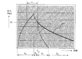
図1は本実施例において該クリ−ニング時、時間軸に対しインク吐出ノズル511に加わる正圧力を表したものである。A〜C及び、Tは加圧ポンプ505もしくは加圧弁520の動作過程を表し、それぞれ
A:加圧動作→ピストン上昇過程
B:待機動作→ピストン停止過程(ここでいう停止過程はピストンが上死点にある)
C:吸入動作→ピストン下降過程(ピストンの位置を下死点に戻し、次の動作に備える)
T::加圧弁開放タイミング
である。
【0034】
加圧動作Aではインク吐出ノズル511近傍の内圧は急激に立ち上がり、本実施例では内圧が30[Kpa]を上回る区間:mで、インク吐出ノズル511から強制的に且つ急激にインクが押し出され、全てのノズルは健全な状態に回復する。
待機動作B中には残留圧力がなだらかに低下して行こうとするが、前記30Kpaを下回る近傍のタイミング:Tで加圧弁520を開放すると、残留圧力は波形101の通り急激に低下するのでクリ−ニングの効果を損なうことなく廃液(廃インク)量を削減することができる。
【0035】
本実施例(実施例1)では該加圧弁開放タイミングは予め装置に設定されたシ−ケンスによって行っているが、本発明においてはかかる手段を限定するものではなく、例えば流路中に圧力センサを設置し、該センサからの検出値をフィ−ドバックする等で行なっても良い。
【0036】
図1内で、該加圧クリ−ニング時に消費する廃インク量を、本実施例による内圧波形101と従来方法の波形102とで比較すると、斜線部は本発明により近似的に削減できる廃インク量を指し示す。
【0037】
廃液量はインク吐出ノズル511に加わる正圧力に対比し、B〜Cに至る間の廃液量が大幅に削減される。
【0038】
尚、該クリ−ニング中に加圧弁520を開放するタイミングXは必ずしも本実施例で述べたタイミングでなく、クリ−ニングによる回復効果の期待値が満たされるのであれば開放タイミングTをより以前にずらすことで、廃インク量は更に削減される。
【0039】
又開放タイミングTを後方にずらすと廃インク量は徐々に増加するが、従来方法の波形102の場合と比較すると廃インクの削減効果が期待できるのは明らかである。
【0040】
【実施例2】
本実施例の場合も加圧ポンプは使用するが、加圧ポンプ505がもつ排出側の弁606(図6参照)は不要である。
【0041】
即ちピストン601を上方向に一度だけ押し上げ加圧回復動作を行い、その後充分なクリ−ニング(回復)効果が得られる圧力を下回った時点で、加圧ポンプ505のピストン601を押し下げて吸入工程に移行させ、シリンダ604内の残留圧力を無くし、結果的に前記インク吐出ノズル511に加わる残留圧力を敏速に低下させる。
【0042】
その間加圧弁520は閉じているが、ピストン601の押し下げ開始後は加圧弁520を開いてもかまわない。
【0043】
図2は本実施例において該クリ−ニング時に時間軸に対しインク吐出ノズル511に加わる正圧力を表したものである。A1〜D1及び、T1は加圧ポンプ505の動作過程を表し、それぞれ
A1:加圧動作→ピストン上昇過程
B1:待機動作→ピストン停止過程(ここでいう停止過程はピストンが上死点にある)
C1:吸入動作→ピストン下降過程
D1:ピストン位置のイニシャライズ
(C1でピストンを下死点まで下げない場合には下死点まで戻し、次の動作に備える)
である。
【0044】
加圧動作A1ではインク吐出ノズル511近傍の内圧は急激に立ち上がり、本実施例では内圧が30[Kpa]を上回る区間:mで、インク吐出ノズル511から強制的に且つ急激にインクが押し出され、各ノズルは健全な状態に回復する。
待機動作B1中には残留圧力がなだらかに低下しようとするが、前記30Kpaを下回る近傍のタイミング:T1で加圧ポンプ505のピストン524を適度に下げ、吸入動作すると、残留圧力は波形201の通り急激に低下するのでクリ−ニングの効果を損なうことなく廃液(廃インク)量を削減することができる。
【0045】
本実施形態においても、実施例1で既述したように、吸入動作B1のタイミングは必ずしも本実施例に沿ったものでなくともよい。
【0046】
【実施例3】
本実施例では加圧ポンプ520に双方向にインクの圧送が可能なポンプを用いる。
【0047】
該ポンプには例えば、チュ−ブポンプ等が用いられる。
【0048】
図3にはチュ−ブ方式の代表的な構成が示してあり、回転体301外周にはコロ支持部材307を介し回転可能にコロ302が取り付けられ、圧縮バネ308によって外周方向に常に押圧を持つよう工夫されているが、ある一定以上は回転体301のストッパ−部にコロ支持部材307の先端部が当接し、抜け止めされる。
【0049】
このようなコロ302、コロ支持部材307、圧縮バネ308は回転体301外周に沿って等間隔に3ケ配置される。また、チュ−ブ303の外周にはチュ−ブ支持部材304がバネ306によりカム305の回転に付随して上下動するように取り付けられる。
【0050】
チュ−ブ303上にあるコロ302は前述したコロ支持部材307が回転体301のストッパ−部に当接した状態より該回転体301の奥方向に退避する状態になる。
【0051】
よって圧縮バネ308によりコロ302が一定圧でチュ−ブ303を押圧し、回転体301を図示せぬ駆動装置により回転すれば、回転方向に沿ってインクを送ることができる。
【0052】
インクを送らない時には図3−bに示すようにカム305を回転させることでチュ−ブ支持部材304はチュ−ブ303と共に下方へ退避し、コロ302がチュ−ブに与える押圧も解除されるためインクの流通性が持たされる。
【0053】
このようなポンプを用い、インク加圧クリ−ニングの際、インク吐出ノズル701に加わる正圧力がノズルから気泡を外部へ排出せしめるに必要な圧力を下回った時点で加圧ポンプを逆転させ、強制的に前記インク吐出ノズル701に加わる残留圧力を低下させる。
【0054】
図4は本実施例において該クリ−ニング時に時間軸に対しインク吐出ノズル701に加わる正圧力を表したものである。A2〜D2及び、T2は加圧ポンプ505の動作過程を表し、それぞれ
A2:ポンプ加圧方向に回転
B2:ポンプ停止
C2:ポンプ逆回転(吸入動作)
D2:回転位置のイニシャライズ
ポンプ加圧動作A2ではインク吐出ノズル511近傍の内圧は急激に立ち上がり、本実施例では内圧が30[Kpa]を上回る区間:mで、インク吐出ノズル511から強制的に且つ急激にインクが押し出され、全てのノズルは健全な状態に回復する。
ポンプ停止中B2では残留圧力がなだらかに低下して行こうとするが、前記30[Kpa]を下回る近傍のタイミング:T2でポンプを逆回転し、吸入動作すると残留圧力は波形401の通り急激に低下するのでクリ−ニングの効果を損なうことなく廃液(廃インク)量を削減することができる。
【0055】
本実施例ではポンプの逆回転開始タイミングは予め装置に設定されたシ−ケンスによって行っているが、本発明においてはかかる手段を限定するものではなく、例えば流路中に圧力センサを設置し、該センサからの検出値をフィ−ドバックする等で行なっても良い。
【0056】
ただし本実施例の場合、前記逆転動作によってインク吐出ノズル511に加わる正圧力を低下させる際には、逆にインク吐出ノズル511に過大な負圧がかかり、インクを該ノズルより後退させないよう、配慮する必要がある。
【0057】
尚、本実施形態においても、既述したように、逆転開始のタイミングは必ずしも本実施例に沿ったものでなくともよい。
【0058】
図7は、本発明を実施した記録装置の電気的なブロック図である。
【0059】
ホストPC700上で作成された記録画像(あるいは印字開始、終了などの動作コマンド)は記録装置のインタフェースコントローラ701で受信される。CPU702は、記録装置の制御を司るもので、ROM703に記憶したプログラム(後述のフローに対応する)に基づき制御を行なう。
【0060】
CPU702の制御(指示)によりメモリコントローラ706を介して取り込んだ画像が色分析等の処理され、各々の記録ヘッド501K〜501Yに対応したビットマップデータがVRAM(Video−RAM)707に展開され、一時的に記憶される。
【0061】
本実施例における記録装置は画像情報、動作コマンドを例えばパラレル通信(IEEE1284)、USB(Universal Serial Bus)、10/100Base−T(ネットワーク)のいずれかで受信し、CPU702が画像情報や動作コマンドの解析を行なった上で、VRAM707に展開される。動作コマンドはRAM704に保存する。
【0062】
各々の記録ヘッド501K〜501LMに対応したビットマップデータの展開が終了し、記録開始を指示する動作コマンドを受信した時点でCPU702は記録処理を実行する。
【0063】
ここでK:ブラック、C:シアン、M:マジェンタ、Y:イエロー、LC:淡シアン、LM:淡マジェンタの各インク色を示す。
【0064】
記録装置全般の制御はROM703に書き込まれた(後述のフローに対応する)制御プログラムをCPU702が実行することにより為される。
【0065】
EEPROM704は、搭載された記録ヘッドの番号、記録ヘッド相互の記録位置(レジストレーション)ずれを補正するための微調整値等記録装置固有の設定値或いは、各種モード等を書き込む不揮発性のメモリである。
【0066】
ここで、EEPROM(Electronic Erasable Programmable Read Only Memory)。
【0067】
記録処理は、入出力(I/O)ポート712、モータ駆動部713を介して記録ヘッド501K〜501LMを上下方向に駆動するヘッドU/Dモータ714、及び待機中記録ヘッドのノズル部511を密閉キャップするキャッピング機構502を搬送方向前後に駆動するキャッピングモータ715を相互に駆動制御して記録ヘッド501K〜501LMをキャッピング位置から記録位置に移動する。
【0068】
次に駆動回路1513〜搬送モータ1516を駆動開始、並行して給紙モータ718を駆動してシートのピックアップ〜分離し、搬送部へ渡す。
【0069】
そして、記録ヘッド501K〜501LMの搬送方向上流部に備えた先端検知センサ721により記録媒体の先端位置が検知され、この位置を基準にして記録開始位置が各記録ヘッドのインク吐出ノズル列の下部に到達したら、VRAM707に記憶された各記録ヘッド501K〜501LMの画像(記録)データの読み出しが開始され、メモリコントローラ706〜記録ヘッド制御回路720を介して記録ヘッド501K〜501LMにデータ転送され、カラー記録される。
【0070】
下流側紙検知センサ119は記録動作済みのシートPの通過状況を監視し、紙ジャム等の検出を行なう。
【0071】
本発明による加圧ポンプ505、廃インク回収ポンプ507はポンプモータ717の駆動により動作する。尚回収ポンプ507は別途独立なモータを使う場合もある。
【0072】
又本発明の加圧弁520の開閉は加圧弁ソレノイド719のON/OFFにより制御する。
【0073】
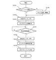
本発明第1実施例に関するCPU702の動作フローを図8にて説明する。
【0074】
先ず記録ヘッド501が密閉キャップ位置にあるかを検知し(S801)、別な位置であったなら(S801−No)、キャップ位置へ移動する(S802)。
【0075】
そして加圧弁ソレノイドをONし、加圧弁520を閉じ(S803)、続いてポンプモータをONしてポンプ505の駆動、記録ヘッドの加圧回復動作を開始し、(S804)各ノズルからインクが強制的に排出される。
【0076】
所定時間経過後(ノズルの健全性が回復できたと判断したら)(S805−Yes)、加圧弁ソレノイドをOFF(S806)、続いてポンプモータもOFFすると(S807)、記録ヘッドの液室内部の正圧力は急激に低下する。
【0077】
従ってその後排出されるインクの量も急激に低下する。
【0078】
以上の加圧回復動作が済んだら不図示のワイパブレードによって記録ヘッドのノズル面インクのワイプ(ふき取り)して終了する。
【0079】
尚加圧回復は所定時間として設定したが、内部に圧力計等を備え、その値をフィードバックする方法でも良い
続いて本発明第2実施例に関するCPU702の動作フローを図9にて説明する。
【0080】
先ず記録ヘッド501が密閉キャップ位置にあるかを検知し(S901)、別な位置であったなら(S901−No)、キャップ位置へ移動する(S902)。
【0081】
そして加圧弁ソレノイドをONし、加圧弁520を閉じ(S903)、続いてポンプモータを加圧方向にONしてポンプ505の駆動、記録ヘッドの加圧回復動作を開始し、(S904)各ノズルからインクが強制的に排出される。ピストン601が上死点で一旦ポンプモータは停止〜待機する。
【0082】
所定時間経過後(ノズルの健全性が回復できたと判断したら)(S905−Yes)、次にはポンプモータを吸引方向にONしピストン601を押し下げると、記録ヘッドの液室内部の正圧力は急激に低下する。
【0083】
従ってその後排出されるインクの量も急激に低下する。
【0084】
尚、ポンプモータの吸引方向ONに伴って加圧弁ソレノイドをOFFし、正圧力低下を促進しても良い。
【0085】
以上の加圧回復動作が済んだら不図示のワイパブレードによって記録ヘッドのノズル面インクのワイプ(ふき取り)して(S908)、終了する。
【0086】
尚加圧回復は所定時間として設定したが、内部に圧力計等を備え、その値をフィードバックする方法でも良い
次に本発明第3実施例に関するCPU702の動作フローを図10にて説明する。
【0087】
本実施例で用いるポンプモータは例えば図3に示したチューブポンプ方式である。
【0088】
先ず記録ヘッド501が密閉キャップ位置にあるかを検知し(S1001)、別な位置であったなら(S1001−No)、キャップ位置へ移動する(S1002)。
【0089】
そして加圧弁ソレノイドをONし、加圧弁520を閉じ(S1003)、続いてポンプモータを加圧方向にONしてポンプ505の駆動、記録ヘッドの加圧回復動作を開始し、(S1004)各ノズルからインクが強制的に排出される。一旦ポンプモータは停止〜待機する。
【0090】
所定時間経過後(ノズルの健全性が回復できたと判断したら)(S1005−Yes)、加圧弁ソレノイドをOFFして(S1006)加圧弁を開くと同時に次にはポンプモータを瞬時逆転し、ポンプを吸引方向に駆動(S1007)、すると記録ヘッドの液室内部の正圧力は急激に低下する。
【0091】
従ってその後排出されるインクの量も急激に低下する。
【0092】
以上の加圧回復動作が済んだら不図示のワイパブレードによって記録ヘッドのノズル面インクのワイプ(ふき取り)して(S1008)、終了する。
【0093】
尚加圧回復は所定時間として設定したが、内部に圧力計等を備え、その値をフィードバックする方法でも良い
【0094】
【発明の効果】
以上説明したように、本発明の実施により、記録ヘッドのインク吐出ノズルから気泡を外部へ排出せしめる、或いは固着が進行したインク吐出ノズルを健全な状態に回復する為に行なう記録ヘッドのインク加圧クリ−ニングにおいて、
加圧後の残留圧力を積極的に低下させることにより、所望のクリ−ニング効果を損なうことなく、加圧クリーニング時消費する廃インク量を減らすことができ、記録装置のランニングコスト低減に寄与する。
【0095】
【図面の簡単な説明】
【図1】本発明第一実施例による{時間×圧力}相関図である。
【図2】本発明第二実施例による{時間×圧力}相関図である。
【図3】チュ−ブポンプ方式の構成例を示す図である。
【図4】本発明第三実施例による{時間×圧力}相関図である。
【図5】インク供給系の構成と流路を示す図である。
【図6】本発明に使用するレシプロポンプの概略図である。
【図7】本発明を実施した記録装置の電気的なブロック図である。
【図8】第一実施例によるインク加圧回復の動作フローである。
【図9】第二実施例によるインク加圧回復の動作フローである。
【図10】第三実施例によるインク加圧回復の動作フローである。
【図11】インク供給、回復系の従来例を示す概略図である。
【符号の説明】
501:記録ヘッド
502:キャッピング機構
503:インクカートリッジ
504:大気連通口
505:加圧ポンプ
511:インク吐出ノズル
512:液室
513:フィルタ
520:加圧弁
601:ピストン
603:カム
604:シリンダ−内液室
605:吸入弁
606:排出弁
700:ホストPC
702:CPU
703:ROM
717:ポンプモータ
719:加圧弁ソレノイド[0001]
BACKGROUND OF THE INVENTION
The present invention relates to an ink supply / recovery mechanism for a recording head in an ink jet printer, and a recording apparatus including the same.
[0002]
[Prior art]
A conventional example relating to an ink supply and recovery system of an ink jet printer is shown in FIG.
[0003]
Ink to be recorded by a large number of
[0004]
During standby, the
[0005]
If the recording operation is continued, bubbles may grow in the vicinity of the
[0006]
In the cleaning (recovery) operation, for example, when the
[0007]
The ink discharged at this time is caught by the
[0008]
Since the waste ink increases when the
(For example, Patent Document 1)
[Patent Document 1]
JP2000-141687 (pages 11 to 12, FIGS. 13, 14, and 15)
[0009]
[Problems to be solved by the invention]
In the case of the conventional method as described above, a sub-tank is required in addition to the replaceable ink cartridge, so that there is some difficulty in downsizing the ink supply system, and the positive pressure quantitative management that cannot be performed quickly is possible. However, there are problems such as requiring a pressure gauge because it is difficult.
[0010]
[Means and Actions for Solving the Problems]
The present invention has been made in view of the above, and in order to solve the above problems, the present invention implemented the following means.
[0011]
That is,
Using a compact mechanism with a pump and a valve, the positive pressure is quickly restored by simple control,
The amount of waste ink was reduced without impairing the recovery operation performance to restore the ink nozzles of the recording head to a healthy state.
[0012]
DETAILED DESCRIPTION OF THE INVENTION
FIG. 5 shows an ink supply channel of the ink jet printer embodying the present invention.
[0013]
This figure shows one station (one color), and when a plurality of recording heads are provided, the same ink flow path is provided in parallel corresponding to each recording head.
[0014]
According to the ink supply device of the present invention, the ink is stored in the casing member, which is an inelastic body, in the
[0015]
A pump used for an operation related to cleaning (recovery) of the
[0016]
Both pumps maintain ink circulation when not driven.
[0017]
FIG. 6 is a cross-sectional view showing the configuration of a reciprocating
[0018]
The
[0019]
In addition, an elastic body 602 that combines the
[0020]
When the
[0021]
There are two modes for the cleaning (recovery) operation of the
[0022]
Ink pressurization cleaning; the
[0023]
Returning to FIG. 5 again, the
[0024]
Then, the pressure-fed ink flows into the
[0025]
As a result, each
[0026]
In the case of the
[0027]
Ink circulation cleaning; an object is to remove bubbles remaining in the ink flow path between the
[0028]
Specifically, by operating the pressurizing
[0029]
Incidentally, the ink forcibly discharged from the
[0030]
The
[0031]
Further, during the recording operation, the pressurizing
[0032]
In this embodiment, at the time of ink pressurization cleaning, the
[0033]
FIG. 1 shows the positive pressure applied to the
C: Inhalation operation → Piston descending process (Return piston position to bottom dead center and prepare for next operation)
T :: Pressurization valve opening timing.
[0034]
In the pressurizing operation A, the internal pressure in the vicinity of the
During the standby operation B, the residual pressure tends to decrease gradually, but when the pressurizing
[0035]
In this embodiment (embodiment 1), the pressurization valve opening timing is performed according to a sequence set in advance in the apparatus. However, in the present invention, such means is not limited. For example, a pressure sensor is provided in the flow path. May be performed by feeding back the detection value from the sensor.
[0036]
In FIG. 1, when the amount of waste ink consumed during the pressure cleaning is compared between the
[0037]
The amount of waste liquid is compared with the positive pressure applied to the
[0038]
Note that the timing X for opening the pressurizing
[0039]
Further, when the opening timing T is shifted backward, the amount of waste ink gradually increases, but it is clear that a waste ink reduction effect can be expected as compared with the
[0040]
[Example 2]
In this embodiment, a pressurizing pump is also used, but the discharge side valve 606 (see FIG. 6) of the pressurizing
[0041]
In other words, the piston 601 is pushed upward once to perform a pressure recovery operation, and thereafter, when the pressure falls below a pressure at which a sufficient cleaning (recovery) effect is obtained, the piston 601 of the
[0042]
During this time, the
[0043]
FIG. 2 shows the positive pressure applied to the
C1: Inhalation operation → Piston descending process D1: Initialization of piston position (If the piston is not lowered to the bottom dead center in C1, it returns to the bottom dead center and prepares for the next operation)
It is.
[0044]
In the pressurizing operation A1, the internal pressure in the vicinity of the
During the standby operation B1, the residual pressure tends to decrease gently, but when the suction operation is performed by appropriately lowering the piston 524 of the pressurizing
[0045]
Also in this embodiment, as already described in the first embodiment, the timing of the suction operation B1 does not necessarily have to follow the present embodiment.
[0046]
[Example 3]
In this embodiment, a pump capable of bi-directional ink feeding is used as the
[0047]
For example, a tube pump or the like is used as the pump.
[0048]
FIG. 3 shows a typical configuration of a tube system. A
[0049]
Three
[0050]
The
[0051]
Therefore, if the
[0052]
When the ink is not sent, the
[0053]
Using such a pump, when the ink pressure cleaning is performed, the pressure pump is reversed and forced when the positive pressure applied to the ink discharge nozzle 701 falls below the pressure necessary for discharging bubbles from the nozzle to the outside. Therefore, the residual pressure applied to the ink discharge nozzle 701 is reduced.
[0054]
FIG. 4 shows the positive pressure applied to the ink discharge nozzle 701 with respect to the time axis during the cleaning in this embodiment. A2 to D2 and T2 represent the operation process of the pressurizing
D2: The internal pressure in the vicinity of the
While the pump is stopped, the residual pressure is going to gradually decrease, but when the pump is reversely rotated at the timing near T: T2 and the suction operation is performed, the residual pressure is abruptly changed according to the waveform 401. Therefore, the amount of waste liquid (waste ink) can be reduced without impairing the cleaning effect.
[0055]
In this embodiment, the reverse rotation start timing of the pump is performed according to a sequence set in advance in the apparatus, but in the present invention, such means is not limited, for example, a pressure sensor is installed in the flow path, The detection value from the sensor may be fed back.
[0056]
However, in the case of the present embodiment, when the positive pressure applied to the
[0057]
In this embodiment as well, as described above, the reverse rotation start timing does not necessarily have to follow the present embodiment.
[0058]
FIG. 7 is an electrical block diagram of a recording apparatus embodying the present invention.
[0059]
A recorded image created on the host PC 700 (or an operation command such as printing start / end) is received by the interface controller 701 of the recording apparatus. The
[0060]
Under the control (instruction) of the
[0061]
The recording apparatus according to the present embodiment receives image information and operation commands by, for example, parallel communication (IEEE1284), USB (Universal Serial Bus), or 10 / 100Base-T (network), and the
[0062]
When the development of the bitmap data corresponding to each of the recording heads 501K to 501LM is completed and an operation command instructing the start of recording is received, the
[0063]
Here, K: black, C: cyan, M: magenta, Y: yellow, LC: light cyan, and LM: light magenta are shown.
[0064]
Control of the entire recording apparatus is performed by the
[0065]
The
[0066]
Here, EEPROM (Electronic Erasable Programmable Read Only Memory).
[0067]
In the recording process, the head U / D motor 714 that drives the recording heads 501K to 501LM in the vertical direction via the input / output (I / O) port 712, the motor driving unit 713, and the
[0068]
Next, driving of the driving circuit 1513 to the conveyance motor 1516 is started, and in parallel, the sheet feeding motor 718 is driven to pick up and separate the sheet, and deliver it to the conveyance unit.
[0069]
The leading
[0070]
The downstream side paper detection sensor 119 monitors the passage state of the sheet P after the recording operation, and detects a paper jam or the like.
[0071]
The
[0072]
The opening / closing of the pressurizing
[0073]
The operation flow of the
[0074]
First, it is detected whether the
[0075]
Then, the pressure valve solenoid is turned on, the
[0076]
After the predetermined time has elapsed (when it is determined that the soundness of the nozzle has been recovered) (S805-Yes), the pressurizing valve solenoid is turned off (S806), and then the pump motor is also turned off (S807). The pressure drops rapidly.
[0077]
Accordingly, the amount of ink discharged thereafter is also rapidly reduced.
[0078]
When the above pressure recovery operation is completed, the ink on the nozzle surface of the recording head is wiped with a wiper blade (not shown), and the process ends.
[0079]
Although the pressure recovery is set as a predetermined time, a method of feeding back the pressure gauge or the like may be used. Next, the operation flow of the
[0080]
First, it is detected whether the
[0081]
Then, the pressurizing valve solenoid is turned on, the pressurizing
[0082]
After a predetermined time has elapsed (when it is determined that the soundness of the nozzle has been recovered) (S905-Yes), when the pump motor is turned on in the suction direction and the piston 601 is pushed down, the positive pressure in the liquid chamber of the recording head suddenly increases. To drop.
[0083]
Accordingly, the amount of ink discharged thereafter is also rapidly reduced.
[0084]
Note that the pressurization valve solenoid may be turned off in accordance with the suction direction of the pump motor being turned on to promote a decrease in positive pressure.
[0085]
When the above pressure recovery operation is completed, the ink on the nozzle surface of the recording head is wiped with a wiper blade (not shown) (S908), and the process ends.
[0086]
Although the pressure recovery is set as a predetermined time, a method of providing a pressure gauge and feeding back the value may be used. Next, the operation flow of the
[0087]
The pump motor used in this embodiment is, for example, a tube pump system shown in FIG.
[0088]
First, it is detected whether the
[0089]
Then, the pressurizing valve solenoid is turned on, the pressurizing
[0090]
After a predetermined time has elapsed (when it is determined that the soundness of the nozzle has been recovered) (S1005-Yes), the pressurization valve solenoid is turned off (S1006) and the pressurization valve is opened. When driven in the suction direction (S1007), the positive pressure inside the liquid chamber of the recording head rapidly decreases.
[0091]
Accordingly, the amount of ink discharged thereafter is also rapidly reduced.
[0092]
When the above pressure recovery operation is completed, the ink on the nozzle surface of the recording head is wiped with a wiper blade (not shown) (S1008), and the process ends.
[0093]
Although the pressure recovery is set as a predetermined time, a method may be used in which a pressure gauge or the like is provided inside and the value is fed back.
【The invention's effect】
As described above, according to the embodiment of the present invention, the recording head ink pressurization is performed to discharge air bubbles from the ink discharge nozzle of the print head to the outside or to restore the ink discharge nozzle that has been fixed to a healthy state. In cleaning,
By actively lowering the residual pressure after pressurization, the amount of waste ink consumed during pressure cleaning can be reduced without impairing the desired cleaning effect, which contributes to reducing the running cost of the printing apparatus. .
[0095]
[Brief description of the drawings]
FIG. 1 is a {time × pressure} correlation diagram according to the first embodiment of the present invention.
FIG. 2 is a {time × pressure} correlation diagram according to the second embodiment of the present invention.
FIG. 3 is a diagram showing a configuration example of a tube pump system.
FIG. 4 is a {time × pressure} correlation diagram according to the third embodiment of the present invention.
FIG. 5 is a diagram illustrating a configuration of an ink supply system and a flow path.
FIG. 6 is a schematic view of a reciprocating pump used in the present invention.
FIG. 7 is an electrical block diagram of a recording apparatus embodying the present invention.
FIG. 8 is an operation flow of ink pressure recovery according to the first embodiment.
FIG. 9 is an operation flow of ink pressure recovery according to the second embodiment.
FIG. 10 is an operation flow of ink pressure recovery according to the third embodiment.
FIG. 11 is a schematic diagram showing a conventional example of an ink supply and recovery system.
[Explanation of symbols]
501: Recording head 502: Capping mechanism 503: Ink cartridge 504: Atmospheric communication port 505: Pressure pump 511: Ink discharge nozzle 512: Liquid chamber 513: Filter 520: Pressure valve 601: Piston 603: Cam 604: Cylinder internal fluid Chamber 605: Suction valve 606: Discharge valve 700: Host PC
702: CPU
703: ROM
717: Pump motor 719: Pressure valve solenoid
Claims (11)
インクを貯蔵するインクカートリッジと、前記インクカートリッジから前記記録ヘッドへインクを加圧供給する加圧ポンプを備える第1のインク経路と、
前記記録ヘッドから前記インクカートリッジ迄の弁を含む第2のインク経路とを備えるインク供給・回復機構において、
前記弁を閉じた後前記加圧ポンプを駆動し、所定時間後前記弁を開放する弁開放手段をもつことを特徴とする記録ヘッドのインク供給・回復機構。A recording head having a plurality of nozzles for ejecting ink;
A first ink path comprising an ink cartridge for storing ink, and a pressurizing pump for pressurizing and supplying ink from the ink cartridge to the recording head;
An ink supply / recovery mechanism comprising a second ink path including a valve from the recording head to the ink cartridge;
An ink supply / recovery mechanism for a recording head, comprising: valve opening means for driving the pressure pump after closing the valve and opening the valve after a predetermined time.
Priority Applications (1)
| Application Number | Priority Date | Filing Date | Title |
|---|---|---|---|
| JP2003173766A JP2005007720A (en) | 2003-06-18 | 2003-06-18 | Ink supply/recovery mechanism and recording device |
Applications Claiming Priority (1)
| Application Number | Priority Date | Filing Date | Title |
|---|---|---|---|
| JP2003173766A JP2005007720A (en) | 2003-06-18 | 2003-06-18 | Ink supply/recovery mechanism and recording device |
Publications (2)
| Publication Number | Publication Date |
|---|---|
| JP2005007720A true JP2005007720A (en) | 2005-01-13 |
| JP2005007720A5 JP2005007720A5 (en) | 2005-08-04 |
Family
ID=34097496
Family Applications (1)
| Application Number | Title | Priority Date | Filing Date |
|---|---|---|---|
| JP2003173766A Pending JP2005007720A (en) | 2003-06-18 | 2003-06-18 | Ink supply/recovery mechanism and recording device |
Country Status (1)
| Country | Link |
|---|---|
| JP (1) | JP2005007720A (en) |
Cited By (6)
| Publication number | Priority date | Publication date | Assignee | Title |
|---|---|---|---|---|
| JP2006231773A (en) * | 2005-02-25 | 2006-09-07 | Sii Printek Inc | Inkjet type recording device |
| JP2007075259A (en) * | 2005-09-13 | 2007-03-29 | Canon Inc | Liquid discharging apparatus |
| JP2007125791A (en) * | 2005-11-04 | 2007-05-24 | Seiko Epson Corp | Liquid jet apparatus and pump control method therefor |
| JP2007216108A (en) * | 2006-02-15 | 2007-08-30 | Hitachi Plant Technologies Ltd | Painting device |
| ES2399478A1 (en) * | 2010-02-05 | 2013-04-01 | Kerajet S.A. | Method and fluid synchrome device. (Machine-translation by Google Translate, not legally binding) |
| CN113001100A (en) * | 2021-02-27 | 2021-06-22 | 常州庆源机械科技有限公司 | Efficient tool applied to rolling thin-wall structural member |
Citations (8)
| Publication number | Priority date | Publication date | Assignee | Title |
|---|---|---|---|---|
| JPH03161350A (en) * | 1989-11-20 | 1991-07-11 | Mita Ind Co Ltd | Discharge restoring device for ink jet printer |
| JPH041055A (en) * | 1990-04-19 | 1992-01-06 | Fuji Xerox Co Ltd | Ink-jet printer |
| JPH0592578A (en) * | 1991-10-02 | 1993-04-16 | Canon Inc | Ink jet recording apparatus |
| JPH0679876A (en) * | 1992-09-02 | 1994-03-22 | Canon Inc | Ink-jet recording device |
| JPH06143601A (en) * | 1992-11-06 | 1994-05-24 | Seiko Epson Corp | Ink jet recorder |
| JPH10138511A (en) * | 1996-11-11 | 1998-05-26 | Canon Aptecs Kk | Ink jet printer |
| JP2000015836A (en) * | 1998-06-30 | 2000-01-18 | Canon Aptex Inc | Ink-jet recording apparatus |
| JP2001232807A (en) * | 2000-02-18 | 2001-08-28 | Canon Aptex Inc | Liquid circulator of ink jet printer |
-
2003
- 2003-06-18 JP JP2003173766A patent/JP2005007720A/en active Pending
Patent Citations (8)
| Publication number | Priority date | Publication date | Assignee | Title |
|---|---|---|---|---|
| JPH03161350A (en) * | 1989-11-20 | 1991-07-11 | Mita Ind Co Ltd | Discharge restoring device for ink jet printer |
| JPH041055A (en) * | 1990-04-19 | 1992-01-06 | Fuji Xerox Co Ltd | Ink-jet printer |
| JPH0592578A (en) * | 1991-10-02 | 1993-04-16 | Canon Inc | Ink jet recording apparatus |
| JPH0679876A (en) * | 1992-09-02 | 1994-03-22 | Canon Inc | Ink-jet recording device |
| JPH06143601A (en) * | 1992-11-06 | 1994-05-24 | Seiko Epson Corp | Ink jet recorder |
| JPH10138511A (en) * | 1996-11-11 | 1998-05-26 | Canon Aptecs Kk | Ink jet printer |
| JP2000015836A (en) * | 1998-06-30 | 2000-01-18 | Canon Aptex Inc | Ink-jet recording apparatus |
| JP2001232807A (en) * | 2000-02-18 | 2001-08-28 | Canon Aptex Inc | Liquid circulator of ink jet printer |
Cited By (8)
| Publication number | Priority date | Publication date | Assignee | Title |
|---|---|---|---|---|
| JP2006231773A (en) * | 2005-02-25 | 2006-09-07 | Sii Printek Inc | Inkjet type recording device |
| JP4602116B2 (en) * | 2005-02-25 | 2010-12-22 | エスアイアイ・プリンテック株式会社 | Ink jet recording apparatus, tube pump, and liquid feeding method |
| JP2007075259A (en) * | 2005-09-13 | 2007-03-29 | Canon Inc | Liquid discharging apparatus |
| JP2007125791A (en) * | 2005-11-04 | 2007-05-24 | Seiko Epson Corp | Liquid jet apparatus and pump control method therefor |
| JP4687397B2 (en) * | 2005-11-04 | 2011-05-25 | セイコーエプソン株式会社 | Liquid ejecting apparatus and pump control method thereof |
| JP2007216108A (en) * | 2006-02-15 | 2007-08-30 | Hitachi Plant Technologies Ltd | Painting device |
| ES2399478A1 (en) * | 2010-02-05 | 2013-04-01 | Kerajet S.A. | Method and fluid synchrome device. (Machine-translation by Google Translate, not legally binding) |
| CN113001100A (en) * | 2021-02-27 | 2021-06-22 | 常州庆源机械科技有限公司 | Efficient tool applied to rolling thin-wall structural member |
Similar Documents
| Publication | Publication Date | Title |
|---|---|---|
| KR101430934B1 (en) | Ink-jet image forming apparatus and method of controlling ink flow | |
| US7984980B2 (en) | Ink cartridge and inkjet recording apparatus | |
| JP2006326855A (en) | Inkjet system image forming apparatus | |
| JP2006327123A (en) | Method of cleaning face surface and inkjet system image forming apparatus | |
| JP2006159811A (en) | Ink supply device and pressure generating method | |
| US20020113836A1 (en) | Image forming method and apparatus therefor | |
| JP7250467B2 (en) | Inkjet recording device and control method | |
| JPH11286124A (en) | Ink nonejection recovery unit for ink jet head | |
| JP2006256024A (en) | Inkjet recorder | |
| JP2006224435A (en) | Inkjet recording device | |
| JP5402033B2 (en) | Image forming apparatus | |
| US20070229614A1 (en) | Inkjet recording apparatus | |
| JP2005007720A (en) | Ink supply/recovery mechanism and recording device | |
| EP1464497B1 (en) | Pump wetting in a liquid ejecting apparatus | |
| JP2000052568A (en) | Ink-jet type recording apparatus and method for controlling cleaning of recording head in this apparatus | |
| JP2012096492A (en) | Inkjet recording device | |
| JP2004098475A (en) | Inkjet recorder | |
| JP2005119287A (en) | Liquid discharge head and inkjet recording device | |
| JP2009248430A (en) | Inkjet recording device, inkjet recording method, recovery device for recording head, and recovering method for recording head | |
| JP4653301B2 (en) | Recording device | |
| JP5001130B2 (en) | Inkjet recording device | |
| JPH07266571A (en) | Ink jet recording apparatus | |
| JP2002103645A (en) | Ink jet recorder | |
| JP2011131491A (en) | Inkjet recorder | |
| JP2005022167A (en) | Inkjet recorder |
Legal Events
| Date | Code | Title | Description |
|---|---|---|---|
| A521 | Written amendment |
Free format text: JAPANESE INTERMEDIATE CODE: A523 Effective date: 20041213 |
|
| A621 | Written request for application examination |
Free format text: JAPANESE INTERMEDIATE CODE: A621 Effective date: 20041213 |
|
| A521 | Written amendment |
Free format text: JAPANESE INTERMEDIATE CODE: A523 Effective date: 20041220 |
|
| A977 | Report on retrieval |
Free format text: JAPANESE INTERMEDIATE CODE: A971007 Effective date: 20070402 |
|
| A131 | Notification of reasons for refusal |
Free format text: JAPANESE INTERMEDIATE CODE: A131 Effective date: 20070626 |
|
| A521 | Written amendment |
Free format text: JAPANESE INTERMEDIATE CODE: A523 Effective date: 20070827 |
|
| A02 | Decision of refusal |
Free format text: JAPANESE INTERMEDIATE CODE: A02 Effective date: 20080212 |