JP2004536978A - Vapor permeable retroreflective clothing - Google Patents
Vapor permeable retroreflective clothing Download PDFInfo
- Publication number
- JP2004536978A JP2004536978A JP2003516308A JP2003516308A JP2004536978A JP 2004536978 A JP2004536978 A JP 2004536978A JP 2003516308 A JP2003516308 A JP 2003516308A JP 2003516308 A JP2003516308 A JP 2003516308A JP 2004536978 A JP2004536978 A JP 2004536978A
- Authority
- JP
- Japan
- Prior art keywords
- retroreflective
- garment
- surface area
- pattern
- article
- Prior art date
- Legal status (The legal status is an assumption and is not a legal conclusion. Google has not performed a legal analysis and makes no representation as to the accuracy of the status listed.)
- Pending
Links
Images


Classifications
-
- A—HUMAN NECESSITIES
- A62—LIFE-SAVING; FIRE-FIGHTING
- A62B—DEVICES, APPARATUS OR METHODS FOR LIFE-SAVING
- A62B17/00—Protective clothing affording protection against heat or harmful chemical agents or for use at high altitudes
-
- A—HUMAN NECESSITIES
- A41—WEARING APPAREL
- A41D—OUTERWEAR; PROTECTIVE GARMENTS; ACCESSORIES
- A41D13/00—Professional, industrial or sporting protective garments, e.g. surgeons' gowns or garments protecting against blows or punches
- A41D13/01—Professional, industrial or sporting protective garments, e.g. surgeons' gowns or garments protecting against blows or punches with reflective or luminous safety means
-
- A—HUMAN NECESSITIES
- A41—WEARING APPAREL
- A41D—OUTERWEAR; PROTECTIVE GARMENTS; ACCESSORIES
- A41D31/00—Materials specially adapted for outerwear
- A41D31/04—Materials specially adapted for outerwear characterised by special function or use
- A41D31/10—Impermeable to liquids, e.g. waterproof; Liquid-repellent
- A41D31/102—Waterproof and breathable
-
- A—HUMAN NECESSITIES
- A41—WEARING APPAREL
- A41D—OUTERWEAR; PROTECTIVE GARMENTS; ACCESSORIES
- A41D31/00—Materials specially adapted for outerwear
- A41D31/04—Materials specially adapted for outerwear characterised by special function or use
- A41D31/32—Retroreflective
-
- A—HUMAN NECESSITIES
- A62—LIFE-SAVING; FIRE-FIGHTING
- A62B—DEVICES, APPARATUS OR METHODS FOR LIFE-SAVING
- A62B99/00—Subject matter not provided for in other groups of this subclass
-
- G—PHYSICS
- G02—OPTICS
- G02B—OPTICAL ELEMENTS, SYSTEMS OR APPARATUS
- G02B5/00—Optical elements other than lenses
- G02B5/12—Reflex reflectors
- G02B5/122—Reflex reflectors cube corner, trihedral or triple reflector type
- G02B5/124—Reflex reflectors cube corner, trihedral or triple reflector type plural reflecting elements forming part of a unitary plate or sheet
-
- G—PHYSICS
- G02—OPTICS
- G02B—OPTICAL ELEMENTS, SYSTEMS OR APPARATUS
- G02B5/00—Optical elements other than lenses
- G02B5/12—Reflex reflectors
- G02B5/126—Reflex reflectors including curved refracting surface
- G02B5/128—Reflex reflectors including curved refracting surface transparent spheres being embedded in matrix
-
- Y—GENERAL TAGGING OF NEW TECHNOLOGICAL DEVELOPMENTS; GENERAL TAGGING OF CROSS-SECTIONAL TECHNOLOGIES SPANNING OVER SEVERAL SECTIONS OF THE IPC; TECHNICAL SUBJECTS COVERED BY FORMER USPC CROSS-REFERENCE ART COLLECTIONS [XRACs] AND DIGESTS
- Y10—TECHNICAL SUBJECTS COVERED BY FORMER USPC
- Y10S—TECHNICAL SUBJECTS COVERED BY FORMER USPC CROSS-REFERENCE ART COLLECTIONS [XRACs] AND DIGESTS
- Y10S2/00—Apparel
- Y10S2/904—Polytetrafluoroethylene
-
- Y—GENERAL TAGGING OF NEW TECHNOLOGICAL DEVELOPMENTS; GENERAL TAGGING OF CROSS-SECTIONAL TECHNOLOGIES SPANNING OVER SEVERAL SECTIONS OF THE IPC; TECHNICAL SUBJECTS COVERED BY FORMER USPC CROSS-REFERENCE ART COLLECTIONS [XRACs] AND DIGESTS
- Y10—TECHNICAL SUBJECTS COVERED BY FORMER USPC
- Y10T—TECHNICAL SUBJECTS COVERED BY FORMER US CLASSIFICATION
- Y10T428/00—Stock material or miscellaneous articles
- Y10T428/24—Structurally defined web or sheet [e.g., overall dimension, etc.]
- Y10T428/24479—Structurally defined web or sheet [e.g., overall dimension, etc.] including variation in thickness
- Y10T428/24521—Structurally defined web or sheet [e.g., overall dimension, etc.] including variation in thickness with component conforming to contour of nonplanar surface
- Y10T428/24545—Containing metal or metal compound
-
- Y—GENERAL TAGGING OF NEW TECHNOLOGICAL DEVELOPMENTS; GENERAL TAGGING OF CROSS-SECTIONAL TECHNOLOGIES SPANNING OVER SEVERAL SECTIONS OF THE IPC; TECHNICAL SUBJECTS COVERED BY FORMER USPC CROSS-REFERENCE ART COLLECTIONS [XRACs] AND DIGESTS
- Y10—TECHNICAL SUBJECTS COVERED BY FORMER USPC
- Y10T—TECHNICAL SUBJECTS COVERED BY FORMER US CLASSIFICATION
- Y10T428/00—Stock material or miscellaneous articles
- Y10T428/24—Structurally defined web or sheet [e.g., overall dimension, etc.]
- Y10T428/24802—Discontinuous or differential coating, impregnation or bond [e.g., artwork, printing, retouched photograph, etc.]
-
- Y—GENERAL TAGGING OF NEW TECHNOLOGICAL DEVELOPMENTS; GENERAL TAGGING OF CROSS-SECTIONAL TECHNOLOGIES SPANNING OVER SEVERAL SECTIONS OF THE IPC; TECHNICAL SUBJECTS COVERED BY FORMER USPC CROSS-REFERENCE ART COLLECTIONS [XRACs] AND DIGESTS
- Y10—TECHNICAL SUBJECTS COVERED BY FORMER USPC
- Y10T—TECHNICAL SUBJECTS COVERED BY FORMER US CLASSIFICATION
- Y10T428/00—Stock material or miscellaneous articles
- Y10T428/28—Web or sheet containing structurally defined element or component and having an adhesive outermost layer
- Y10T428/2804—Next to metal
-
- Y—GENERAL TAGGING OF NEW TECHNOLOGICAL DEVELOPMENTS; GENERAL TAGGING OF CROSS-SECTIONAL TECHNOLOGIES SPANNING OVER SEVERAL SECTIONS OF THE IPC; TECHNICAL SUBJECTS COVERED BY FORMER USPC CROSS-REFERENCE ART COLLECTIONS [XRACs] AND DIGESTS
- Y10—TECHNICAL SUBJECTS COVERED BY FORMER USPC
- Y10T—TECHNICAL SUBJECTS COVERED BY FORMER US CLASSIFICATION
- Y10T428/00—Stock material or miscellaneous articles
- Y10T428/31504—Composite [nonstructural laminate]
- Y10T428/31551—Of polyamidoester [polyurethane, polyisocyanate, polycarbamate, etc.]
- Y10T428/31554—Next to second layer of polyamidoester
Abstract
Description
【技術分野】
【0001】
本開示は、再帰反射性材料に係り、特に、保護服に用いられる再帰反射性材料に関する。
【背景技術】
【0002】
再帰反射性材料は、いくつか例を挙げると、道路標識、ナンバープレート、靴および衣服のパッチ等の様々な用途に用いるために開発されてきた。再帰反射性材料は、着用者の視認性を増大するために、衣服の高視認性トリム材料として用いられることが多い。例えば、再帰反射性材料は、消防士、レスキュー隊員、EMS技術者等により着用される保護服に付けられることが多い。
【0003】
再帰反射性は、アルミニウムのコート層のような反射剤と協働する小さなガラスビーズまたはマイクロスフェアの層の使用をはじめとする様々な方法で与えることができる。ビーズが大気に部分的に露出されるように布帛にビーズを保持するバインダー層にビーズを部分的に埋め込むことができる。バインダー層中に埋め込まれたビーズの背面に配置された反射剤のビーズにより、ビーズの露出部分に入る入射光が集束される。反射剤は、ビーズを通る入射光を反射し、入射方向とは逆の方向に、ビーズの露出部分を通して光が出て行く。
【0004】
再帰反射性材料は、夜間および深夜時間帯の消防およびレスキュー隊員の視認性を増大させるのに、特に有用となり得る。しかしながら、状況によっては、消防服は火事の際に極限温度に晒され、再帰反射性材料が衣服内側に熱を取り込む可能性がある。特定の条件下では、取り込まれた熱は、不快さばかりか、消防士の皮膚を火傷させてしまう可能性がある。
【0005】
特に、再帰反射性材料に集まった蒸気は、火事の極限温度に晒されると即時に膨張する恐れがある。膨張した蒸気が再帰反射性材料を即時に透過できない場合には、消防士が極限温度に晒される恐れがある。場合によっては、この結果、再帰反射性材料を有する衣服部分の下にある消防士の皮膚が蒸気で火傷する恐れがある。穿孔された再帰反射性材料をはじめとする従来の再帰反射性材料は一般的にこの現象を呈す。例えば、従来の穿孔された再帰反射性材料は、ニードルパンチ孔、レーザーパンチ孔、スリットまたはペーパーパンチにより作成された比較的大きな孔を有する標準再帰反射性トリムを含んでいる。
【0006】
本開示には、主に、保護服に用いられる蒸気透過性再帰反射性材料が記載されている。例えば、この材料は不連続パターンで形成され、高レベルの再帰反射輝度を与え、かつ、加熱された蒸気への露出および極限温度への長時間の露出を防ぐ適正な蒸気透過性を与えることができる。
【0007】
特に、不連続パターンには、再帰反射性領域と非再帰反射性領域が含まれる。これらの領域は、再帰反射性領域が熱崩壊または蒸気透過性を大幅に減少させないように構成されている。というよりも、保護服の蒸気透過性および熱崩壊は、再帰反射性パターンが存在しなかったかのようにほぼ同じである。
【発明の開示】
【課題を解決するための手段】
【0008】
一態様において、衣服には、消防士の装備の外殻のような保護外側層と、保護外側層の第1の部分を覆うように形成された反射性材料とが含まれる。再帰反射性材料は、再帰反射性領域と非再帰反射性領域とを画定する不連続パターンで形成することができる。第1の部分の熱崩壊は、再帰反射性材料でカバーされていない保護服の第2の部分の熱崩壊とほぼ同じである。あるいは、またはさらに、第1の部分の蒸気透過性は、再帰反射性材料でカバーされていない保護服の第2の部分の蒸気透過性とほぼ同じである。衣服は、消防士の装備の外殻を含み、第1の部分は消防士の装備の外殻に再帰反射性トリムを含んでいる。ある態様において、不連続再帰反射性パターンで形成された第1の部分の反射輝度は50カンデラ/(ルクス*平方メートル)を超える、さらには250カンデラ/(ルクス*平方メートル)を超える。
【0009】
他の態様において、保護装備は、第1の層、第2の層および第3の層を含む。第1の層は、再帰反射性領域と非再帰反射性領域を有する不連続再帰反射性部分と、再帰反射性領域を有さない第2の部分を含む外殻であってもよい。さらに、不連続再帰反射性部分の蒸気透過性および/または熱崩壊は、第2の部分の蒸気透過性とほぼ等しい。保護保護装備は、第2の層が蒸気バリアで、第3の層が熱ライナである消防士の装備であってもよい。あるいは、保護装備は、第2の層が液体保持層であり、第3の層が耐水性の蒸気透過性層である熱制御装備であってもよい。同様に、不連続再帰反射性パターンの反射輝度は50カンデラ/(ルクス*平方メートル)を超える、さらには250カンデラ/(ルクス*平方メートル)を超える。
【0010】
他の態様において、物品は、消防士の装備の外殻と同じ材料でできた耐久性のある布裏打のような第1の材料を含んでいてもよい。さらに、物品は、再帰反射性領域と非再帰反射性領域とを画定する不連続パターンに従って第1の材料に形成された再帰反射性材料を含んでいてもよい。再帰反射性材料は、物品の熱崩壊を大幅に減少させないように構成することができる。これらの再帰反射性領域と蒸気透過性非再帰反射性領域は、詳細を後述している様々な異なる構成を形成してもよい。再帰反射性領域があると、物品の熱崩壊または蒸気透過性が大幅に減少することはない。具体的な例を挙げると、物品は衣服として用いるために再帰反射性パッチを含んでいる。不連続パターンを画定する材料の反射輝度は50カンデラ/(ルクス*平方メートル)を超える、さらには250カンデラ/(ルクス*平方メートル)を超える。
【0011】
さらに他の態様において、この開示には1つ以上の方法が記載されている。例えば、この方法には、接着パターンを保護服にスクリーン印刷する工程と、再帰反射性ビーズを接着パターンに押し付けて再帰反射性パターンを作成する工程が含まれる。再帰反射性パターンを有する部分における保護服の保護蒸気透過性および/または熱崩壊は、再帰反射性パターンを有さない衣服の部分における保護服の蒸気透過性および/または熱崩壊とほぼ同じである。
【0012】
あるいは、本方法には、再帰反射性ビーズを接着剤材料に混合する工程と、この混合物を用いて保護服にパターンをスクリーン印刷する工程とが含まれる。同様に、スクリーン印刷されたパターンを有する部分における保護服の保護蒸気透過性および/または熱崩壊は、スクリーン印刷されたパターンを有さない衣服の部分における保護服の蒸気透過性および/または熱崩壊とほぼ同じである。
【0013】
不連続蒸気透過性材料はいくつかの利点をもたらす。特に、穿孔された再帰反射性材料をはじめとする従来の再帰反射性材料とは異なり、不連続蒸気透過性材料は、再帰反射性材料を有する保護服の熱および蒸気移動を改善することができる。蒸気透過性および熱崩壊を減少する恐れのある従来の穿孔された再帰反射性材料とは異なり、本開示によれば、衣服の蒸気透過性に大幅に影響を与えることなく保護服に再帰反射性材料を固定する技術が提供され、これによって、加熱された蒸気および極限温度による負傷の危険が減じる。さらに、ここに記載された技術によって、穿孔された再帰反射性材料のような従来の再帰反射性材料を用いる場合と違って、外殻の熱崩壊が改善されて、保護装備内に取り込まれた熱を逃がすことができる。
【0014】
不連続再帰反射性材料のその他の利点は、極限温度により衣服の着用者を負傷させるリスクをなくして、保護服に高再帰反射性材料を用いることができることである。再帰反射性材料を用いることは、視認性が低い夜間や深夜の時間帯には特に重要である。衣服の蒸気透過性および熱崩壊を大幅に変えずに、50カンデラ/(ルクス*平方メートル)を超える、さらには250カンデラ/(ルクス*平方メートル)を超える反射輝度を有する不連続再帰反射性材料を作成することができる。
【0015】
さらに、スクリーン印刷技術またはここに記載したその他の技術を用いて保護装備の再帰反射性材料を与えると、保護装備の作成が改善される。さらに、後述するようにして作成された再帰反射性パターンは、従来の保護服に用いられる従来の再帰反射性材料よりも薄く、かなり嵩高さが減る。
【0016】
これらのおよびその他の実施形態の更なる詳細については、添付の図面および以下の説明に示してある。その他の特徴、目的および利点は、説明、図面および請求項から明白となろう。
【発明を実施するための最良の形態】
【0017】
本開示には、主に、保護服に用いられる蒸気透過性再帰反射性材料が記載されている。この材料は不連続再帰反射性パターンを含んでおり、高レベルの再帰反射輝度を与え、かつ、加熱された蒸気および極限温度に露出されるのを防ぐ適正な蒸気透過性を与える。
【0018】
衣服そのもの、すなわち、保護装備の外側層または外殻について記載してある場合もある。他の場合においては、保護服に付けられる衣服パッチのような物品について記載してある。さらに他の場合においては、外殻に不連続再帰反射性パターンと、熱ライナおよび蒸気バリアのような追加の層を含む保護装備について記載してある。
【0019】
不連続再帰反射性パターンには、再帰反射性領域と非再帰反射性領域が含まれる。しかしながら、従来の再帰反射性材料とは異なり、再帰反射性領域があると、材料の熱崩壊または蒸気透過性が大幅に減少することはない。すなわち、材料の熱崩壊および蒸気透過性は、再帰反射性パターンによって大幅に減少することはない。というよりも、材料の蒸気透過性および熱崩壊は、再帰反射性パターンが存在しなかったかのようにほぼ同じである。一般に、蒸気透過性は、蒸気が材料を移動する速度の尺度である。熱崩壊は、熱が材料から逃れる速度の尺度である。
【0020】
図1に、消防士が着用する保護装備の外殻のような保護服10を示す。保護服10には、再帰反射性領域と非再帰反射性領域とを画定する第1の部分12を覆うように不連続パターンで形成された再帰反射性材料を有する外殻が含まれる。第2の部分14は再帰反射性領域を有していない。詳細を後述してあるように、第1の部分12の熱崩壊は、第2の部分14の熱崩壊にほぼ等しい。さらに、第1の部分12の蒸気透過性は、第2の部分14の蒸気透過性にほぼ等しい。
【0021】
第1の部分12は、不連続再帰反射性パターンで形成された布地パッチのような物品を含んでいてもよい。あるいは、不連続再帰反射性パターンは、後述するように保護服10の表面に直接印刷されていてもよい。重要なのは、保護服に用いられている従来の再帰反射性材料とは異なり、第1の部分12が保護服10の内側に熱や蒸気を取り込まないことである。衣服10にはまた、日中の衣服10の視認性を改善するために、その他の非再帰反射性蛍光材料(図示せず)も含まれている。
【0022】
図2〜5に、第1の部分12に形成された再帰反射性材料の数多くの例証の不連続パターンを示す。特に、再帰反射性材料は、これらのおよび同様の不連続パターンで、保護服10に縫い付けられた、またはその他のやり方で付けられたパッチまたはその他材料に適用してもよい。例えば、再帰反射性材料は、後述するように、テープ状材料から材料をスクリーン印刷または熱転写により適用してもよい。ある態様において、再帰反射性材料は、第1の位置12を実現するために、保護服10に直接適用してもよい。当然、図2〜5に示すパターンは例証のためのみであり、その他のパターンを用いることができる。
【0023】
図2に、再帰反射性領域22と蒸気透過性の非再帰反射性領域24とを画定する例証の不連続パターン20を示す。この構成において、再帰反射性領域22と蒸気透過性の非再帰反射性領域24は、再帰反射性材料の約50パーセントの表面積を有するチェッカー盤状構成を形成している。具体的な例を挙げると、蒸気透過性の非再帰反射性領域24と再帰反射性領域22は、約0.3175センチメートルの側部を有している。その場合、再帰反射性領域は、ほぼ1平方センチメートル未満の表面積を有している。
【0024】
従来の再帰反射性材料は、衣服の蒸気透過性および熱崩壊を大幅に減じる可能性がある。不連続パターン20を用いるとこの問題が解決される。というのは、蒸気透過性の非再帰反射性領域24が十分な割合の不連続パターン20を含んでいて、蒸気と熱を逃すからである。しかしながら、非再帰反射性領域24があると、パターンの反射輝度が減じる。例えば、非再帰反射性領域24が不連続パターンの表面積の50パーセントとなると、反射輝度は、再帰反射性材料が連続パターンで適用されている場合よりも少なく、約50パーセント未満となる。
【0025】
非再帰反射性領域の表面積は、衣服の蒸気透過性および熱崩壊を増大させないよう、再帰反射性材料の総表面積の少なくとも約20%である必要がある。図2〜5の実施例は全て、蒸気および熱を適切に逃がすのに有効なものである。再帰反射性材料の総表面積の20%を超える、25%を超える、50%を超える非再帰反射性領域は特に有効でありうる。
【0026】
蒸気透過性および熱崩壊に影響する恐れのあるその他の因子は、個々の再帰反射性領域および個々の非再帰反射性領域のサイズである。特に、各再帰反射性領域は、材料から蒸気および熱を逃がすことができるよう十分小さい必要がある。4平方センチメートル未満、場合によっては1平方センチメートル未満の表面積をそれぞれ有する再帰反射性領域で十分である。これによって、不連続再帰反射性パターン20(図2)で形成された部分12(図1)の熱崩壊および蒸気透過性を、再帰反射性領域22を有さない部分14のような同様の材料の熱崩壊および蒸気透過性とほぼ同じにできるようになる。
【0027】
図3に、再帰反射性領域32と蒸気透過性の非再帰反射性領域34とを画定する例証の不連続パターン30を示す。この構成において、再帰反射性領域32および蒸気透過性の非再帰反射性領域34はストライプ状構成を形成する。すなわち、非再帰反射性領域34は、再帰反射性領域32を分割するストライプ状領域を含んでいる。ストライプ状構成は、約66パーセントの再帰反射性領域32と約33パーセントの蒸気透過性の非再帰反射性領域34とを含む表面積を有している。具体的な例を挙げると、非再帰反射性領域34の幅は約0.3175センチメートルであり、再帰反射性領域32の幅は約0.635センチメートルである。不連続再帰反射性パターン30で形成された部分12(図1)の熱崩壊および蒸気透過性は、再帰反射性領域を有さない部分14のような同様の材料の熱崩壊および蒸気透過性とほぼ同じである。
【0028】
図4に、再帰反射性領域42と蒸気透過性の非再帰反射性領域44とを画定する例証の不連続パターン40を示す。この構成において、再帰反射性領域42および蒸気透過性の非再帰反射性領域44は三角形領域が除去されたパターンを形成する。一例を挙げると、再帰反射性領域42は、不連続パターン40の表面積の約75パーセントである。他の例を挙げると、再帰反射性領域42は、不連続パターン40の表面積の約50パーセントである。不連続再帰反射性パターン40で形成された部分12(図1)の熱崩壊および蒸気透過性は、再帰反射性領域を有さない部分14のような同様の材料の熱崩壊および蒸気透過性とほぼ同じである。さらに他の態様において、再帰反射性領域と非再帰反射性領域は三角形領域を有している。
【0029】
図5に、再帰反射性領域52と蒸気透過性の非再帰反射性領域54とを画定する例証の不連続パターン50を示す。この構成において、再帰反射性領域52は、非再帰反射性領域54内に円形領域を含んでいる。不連続再帰反射性パターン50で形成された部分12(図1)の熱崩壊および蒸気透過性は、再帰反射性領域を有さない部分14のような同様の材料の熱崩壊および蒸気透過性とほぼ同じである。
【0030】
図6は、図2〜5に示したものと同様の不連続な蒸気透過性再帰反射性パターンを形成するのに用いることのできるスクリーン印刷プロセスの流れ図である。上述したように、パターンは、保護服10(図1)に縫い付けることのできるパッチに適用することができる。この代わりに、衣服10の一部にパターンを直接適用して、不連続再帰反射性部分12を形成することもできる。
【0031】
蒸気透過性の再帰反射性材料は、不連続パターン(62)を画定し、再帰反射性ガラスビーズを樹脂(64)に混合し、混合物を画定されたパターン(66)に従って物品にスクリーン印刷することによって形成することができる。再帰反射性ビーズはアルミニウムで半分コートされていてもよい。例えば、好適なビーズは、ミネソタ州、セントポールのミネソタマイニング・アンド・マニュファクチュアリング(Minnesota Mining and Manufacturing Company of St. Paul, Minnesota)より市販されている145番反射性ガラス要素である。混合物のスクリーン印刷後、ビーズは樹脂内に不規則に配向される。混合物のスクリーン印刷後、混合物を数多くある技術に従って硬化または乾燥させる。図6のプロセスにより得られる反射輝度は、ビーズが不規則に配向されることから、総適用範囲についてわずか約25カンデラ/(ルクス*平方メートル)でしかない。同一の譲渡人に譲渡された米国特許第5,269,840号には、図6に示したのと同様のいくつかのプロセスの詳細が記載されている。
【0032】
再帰反射性材料の反射輝度は、標準的な再帰反射性条件下、例えば、0°の配向角、−4°の入口角および0.2°の観察角で見たときの物品の見かけの輝度の尺度である。輝度は、物品の面積および用いた光源からの照度について標準化される。反射率または反射輝度はまた、再帰反射性係数(RA)とも呼ばれ、カンデラ/(ルクス*平方メートル)の単位で表される。ASTM標準方法808−94番「再帰反射性を求める標準的手法」を参照されたい。
【0033】
上述した通り、蒸気透過性の再帰反射性材料の反射輝度は、再帰反射性領域を含む表面積の割合に関係している。例えば、パターンが約50パーセントの再帰反射性領域と約50パーセントの非再帰反射性領域で画定される表面積を有している場合、図6の技術を用いると反射輝度はわずか約12.5カンデラ/(ルクス*平方メートル)である。ある用途については十分な輝度であるが、他の用途については不十分である。例えば、夜間や深夜の時間帯に消防士がドライバーに目視されるよう消防士の服の反射輝度は最大とするのが望ましい。
【0034】
図7には、図2〜5に示したのと同様の不連続再帰反射性パターンを作成するのに用いることのできるプロセスが示されており、反射輝度は50カンデラ/(ルクス*平方メートル)を超える。場合によっては、輝度は250カンデラ/(ルクス*平方メートル)を超える。
【0035】
図7のプロセスには、パターン(72)を画定し、接着剤を画定されたパターン(74)に従って材料にスクリーン印刷することが含まれる。例えば、材料は保護服の一部を含んでいたり、保護服に用いられるパッチを含んでいてもよい。再帰反射性ビーズを接着剤パターンに押し付けて再帰反射性パターン(76)を作成してもよい。
【0036】
再帰反射性ビーズを接着パターン(76)に押し付けるのは、数多くのやり方で行うことができる。一例を挙げると、ガラスビーズをまず基材上に付着させて、ビーズの露出面をアルミニウムでコートする。基材をスクリーン印刷された接着剤に押し付けて、接着剤中にビーズを固定する。基材を剥すと、接着剤に適切に配置されたアルミニウムで半分コートされたビーズが残る。かかる方法によって、総適用範囲について約500カンデラ/(ルクス*平方メートル)を超える反射輝度が得られる。このように、パターンが50パーセントの適用範囲を画定する場合、材料の反射輝度は約250カンデラ/(ルクス*平方メートル)となる。パターンが66パーセントの適用範囲を画定する場合、材料の反射輝度は約330カンデラ/(ルクス*平方メートル)となる。パターンが75パーセントの適用範囲を画定する場合、材料の反射輝度は約375カンデラ/(ルクス*平方メートル)となる。
【実施例】
【0037】
実施例1
ミネソタ州、セントポールのミネソタマイニング・アンド・マニュファクチュアリング(Minnesota Mining and Manufacturing Company of St. Paul, Minnesota)(以降3Mとする)より市販されている5720 3M(商標)スコッチライト(Scotchlite)(商標)シルバーグラフィック転写フィルム(Silver Graphic Transfer Film)を用いて不連続蒸気透過性再帰反射性材料としてみた。グラフィック画像を作成し、ジョージア州ユニオンシティのサザンミル(Southern Mills of Union City, Georgia)より入手可能なPVI/ケブラー(PVI/Kevlar)(登録商標)混紡布帛を含むコンバット(Kombat)(商標)に転写した。グラフィック画像が付いた布帛を試験した。グラフィック画像を不連続再帰反射性パターンの一例として用いた。具体的には、以下の手順に従って試料を作成した。
【0038】
5720シルバーグラフィック転写フィルム(Silver Graphic Transfer Film )(ポリエステルキャリアを備えたSFEE1134−3−2−1A)を、3M(商標)571Nカプラー(A−1120シラン、4重量%)で変性した、ウィスコンシン州サセックスのプラスト−O−メリックSP社(Plast−O−Meric SP, Inc., Sussex, Wisconsin)より入手可能なSX779B FR印刷接着剤(SX 779B FR Printable Adhesive )(難燃性SX864Bプラスチゾルインク)でスクリーン印刷した。ウィスコンシン州オシコシのアメリカンM&Mスクリーン印刷機器(American M & M Screen Printing Equipment of Oshkosh, Wisconsin)より入手可能なカメオ(Cameo)プリンタを用いて、中硬スキージにより5720グラフィック転写フィルムに110T/in(43.3T/cm)印刷スクリーンを通してインクを印刷した。スクリーンの版下は、異なるグラフィックパターン(チェッカー盤、ハッシュマークおよび円)を備えた3本のストライプからできていた。ベルト温度が華氏230度(摂氏110度)のイリノイ州シカゴのアメリカンスクリーン印刷機器社(American Screen Printing Equipment Co., Chicago, Illinois)より入手可能なテクスエア(Texair)(商標)型番30コンベヤーオーブンに通過させることにより、得られた印刷をゲル化した。オーブンを、華氏1100度(摂氏593度)に設定されたIRパネルにより加熱し、ベルト温度をベルト速度により制御した。ゲル化後、 エアライン圧40psi(276kPa)で30秒間華氏340度(摂氏171度)に設定されたカンサス州ピッツバーグのHIX社(HIX Corp. of Pittsburg, KS)より入手可能なHIX N−800プレスを用いて、印刷されたグラフィック画像をコンバット(Kombat)(商標)布帛にラミネートした。試料を室温まで冷やした後、ポリエステルキャリアを除去したところ、シルバーグラフィック画像がコンバット(Kombat)(商標)布帛に得られた。シルバー画像を含むこのコンバット(Kombat)(商標)布帛を、図8に示す保護装備を形成する右上隅の残りの2層に縫い付けた。この完成品を、標準的な工業試験手順に沿った手順に従って試験した。
【0039】
接着パターンに再帰反射性ビーズを押し付ける他のやり方は、完全にアルミニウムでコートされたビーズを接着剤に付着させて、ビーズの露出面からアルミニウムをエッチングするものである。かかるプロセスは連続しており、剥したり、基材を廃棄する必要がない。このプロセスの詳細については、同時係属の同一の譲渡人に譲渡されたPCT出願公開、国際公開第0142823(A1)号パンフレットに記載されている。この方法によって、総適用範囲について約350カンデラ/(ルクス*平方メートル)以上の反射輝度が得られる。このように、パターンが50パーセントの適用範囲を画定する場合、材料の反射輝度は約175カンデラ/(ルクス*平方メートル)となる。パターンが66パーセントの適用範囲を画定する場合、材料の反射輝度は約231カンデラ/(ルクス*平方メートル)となる。パターンが75パーセントの適用範囲を画定する場合、材料の反射輝度は約263カンデラ/(ルクス*平方メートル)となる。
【0040】
図6または7のプロセスに更に代わるものとして、図2〜5に示したのと同様のパターンを有する不連続蒸気透過性再帰反射性材料は次のようにして作成することができる。ガラスビーズをまず基材上に付着およびボンドさせて、ビーズの露出面をアルミニウムでコートする。接着剤をガラスビーズの上部に適用して、再帰反射性テープ状材料を作成する。テープ状材料を、消防士装備のパッチや外殻のような材料に押し付ける前に、パターンをテープ状材料へと切断する。熱および圧力を印加して、基材を剥がすと、接着剤に適切に配向され、下にある材料に付着して不連続蒸気透過性再帰反射性材料を画定するアルミニウムで半分コートされたビーズのパターンが残る。
【0041】
実施例2
3Mより市販されている8710 3M(商標)スコッチライト(Scotchlite)(商標)シルバー転写フィルムをまた用いて不連続蒸気透過性材料とした。8710シルバーグラフィック画像を作成し、ジョージア州ユニオンシティのサザンミル(Southern Mills of Union City, Georgia)より入手可能なノーメックス(Nomex)(登録商標)外殻材料に転写した。ノーメックス(Nomex)(登録商標)外殻材料を試験した。グラフィック画像を不連続蒸気透過性再帰反射性材料の他の例として用いた。
【0042】
具体的には、以下の手順に従って8710シルバーグラフィック画像を作成した。8710シルバー転写フィルム(75−0001−6745−4)グラフィック画像をプロッタ切断し、ウィード(weed)を除去し、材料を、 エアライン圧40psi(276kPa)で15秒間華氏338度(摂氏170度)に設定されたカンサス州ピッツバーグのHIX社(HIX Corp. of Pittsburg, KS)より入手可能なHIX N−800プレスを用いて、ノーメックス(Nomex)(登録商標)外殻材料にラミネートした。試料を室温まで冷やした後、紙キャリアを除去したところ、シルバーグラフィック画像がノーメックス(Nomex)(登録商標)外殻材料に得られた。シルバー画像を含むこの材料を、保護装備を形成する他の層に(右上隅に縫い付けることにより)付けた。この完成品を、標準的な工業試験手順にほぼ沿った手順に従って試験した。
【0043】
上述したようにして作成された不連続蒸気透過性再帰反射性材料は、従来技術では得られなかった熱崩壊特性および蒸気透過性特性を示す。特に、不連続再帰反射性材料の熱崩壊および蒸気透過性は、下にある材料と同じであってもよい。すなわち、再帰反射性材料のパターンを追加しても、材料の蒸気透過性または材料の熱崩壊のいずれかは大幅に変わらない。この理由から、不連続蒸気透過性再帰反射性材料は、消防士の保護服の性能を改善することができる。
【0044】
スクリーン印刷技術を用いて保護服に、または熱を与える不連続再帰反射性テープ状材料に再帰反射性材料を与えると、保護服の作成に関する製造プロセスを改善することができる。さらに、不連続再帰反射性パターンは、従来の保護服に用いられる従来の再帰反射性材料よりも薄く、かなり嵩高さが減る。さらに、得られる不連続蒸気透過性再帰反射性材料は穿孔しなくてよいため、製造プロセスにおける穿孔工程を省くことができる。
【0045】
図8は、多層保護消防士装備の断面図である。消防士装備80には、再帰反射性部分84を有する外殻82が含まれる。消防士装備80にはまた、蒸気バリア86と熱ライナ88も含まれる。再帰反射性部分84には、不連続パターンで形成された再帰反射性材料がある。部分84は、外殻82に縫い付けられた、またはその他のやり方で付けられたパッチであってもよい。あるいは、部分84は、上述した通り、外殻82に直接スクリーン印刷された不連続再帰反射性パターンを含んでいてもよい。
【0046】
外殻82は、消防士保護標準装備に用いられる代表的な外殻を表している。例えば、外殻は、消防士を引っ掻き傷や擦過傷から守るものであり、撥水剤等でコートされていてもよい。一例を挙げると、ジョージア州ユニオンシティのサザンミル(Southern Mills of Union City, Georgia)より入手可能なPVI/ケブラー(PVI/Kevlar)(登録商標)混紡布帛を含むコンバット(Kombat)(商標)がある。
【0047】
蒸気バリア86を用いて、液体が熱ライナ88へ浸透するのを防ぐことができる。以前の消防士装備は、蒸気不透性の蒸気バリアを用いていた。しかしながら、新規なデザインでは着用者に快適さを与える蒸気透過性の蒸気バリアを利用している。蒸気バリア86が蒸気透過性である場合には、熱蒸気が着用者の皮膚を透過して、蒸気が外殻を通ったり、再帰反射性材料を備えた外殻を通って逃げない場合には不快になったり火傷となる可能性がある。従って、蒸気透過性蒸気バリアを用いることは、不連続蒸気透過性再帰反射性材料に求められる理由の一つである。好適な蒸気透過性蒸気バリアの一例を挙げると、メリーランド州エルクトンのW.Lゴア(W.L Gore of Elkton, Maryland)より入手可能なノーメックス(Nomex)(登録商標)パジャマチェック材料のクロステック(Corsstech)(商標)がある。
【0048】
熱ライナ88を用いて着用者を極限温度から保護することができる。好適な熱ライナの一例を挙げると、ジョージア州ユニオンシティのサザンミル(Southern Mills of Union City, Georgia)より入手可能な100%ノーマックス(Nomax)(登録商標)上面布を備えた100%ケブラー(Kevlar)(登録商標)バットを含むアラライト(Aralite)(登録商標)材料がある。
【0049】
図9および10は、従来技術の消防服と不連続パターンで形成された再帰反射性材料を用いて作成された消防服の蒸気透過性試験で収集された実験データをまとめたグラフである。ローソン、J.ランドール(Lawson, J. Randall)およびツイリー、ウィリアムH.(Twilley, William H.)「消防士保護服の熱性能を測定するための装置開発(Development of an Apparatus for Measuring the Thermal Performance of Firefighters Protective Clothing)」、ミッドランド州ゲイザースバーグの規格技術学会(National Institute of Standards and Technology, Gaithersburg, MD)、1999年(NISTIR 6400)およびアメリカ試験材料学会(American Society for Testing and Materials)、E162「放射熱エネルギー源を用いた材料の表面可燃度の標準試験方法(Standard Test Method for Surface Flammability of Materials Using a Radiant Heat Energy Source)」、ASTM規格アニュアルブック(ASTM Annual Book of Standards)、第04.07巻、ペンシルバニア州、ウェストコンショーホッケン(West Conshohocken, PA)1997年を参照されたい。後述する様々な試験および実験は、上述の参考文献に記載された工業規格試験方法にほぼ沿ったものであった。
【0050】
特に、図9に、部分84に不連続蒸気透過性再帰反射性材料(図8)ではなく再帰反射性の標準トリム材料を用いる従来技術の構造の蒸気透過性を示す。図10に、部分84に不連続パターンで形成された再帰反射性材料を用いる衣服の蒸気透過性を示す。いずれの場合においても、衣服には熱を与え、各衣服の特定の部分の温度を経時で記録した。
【0051】
図9に、部分84に不連続蒸気透過性再帰反射性材料ではなく従来技術の再帰反射性標準トリム材料を用いた消防服のC点(図8)で測定した時間の関数としての温度をライン92でグラフにしてある。同様に、ライン94は、従来技術の消防服のD点で測定した温度を示す。約70秒後、C点での温度はD点での温度より熱くなった。これは、少なくとも一部は、熱蒸気が従来技術の再帰反射性材料を適切に透過できず、蒸気透過性蒸気バリア86を流れてC点の温度を即時に上げる、という事実によるものである。実験において、熱蒸気の質量移動は、従来技術の再帰反射性材料により覆われた領域において熱ライナ88で蒸気が凝縮したことで目視により明らかであった。穿孔された従来技術の再帰反射性材料も同様の結果を示した。
【0052】
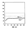
従来の再帰反射性材料とは異なり、部分84に不連続再帰反射性材料を用いると所望の蒸気透過性が得られた。図10に、部分84に不連続蒸気透過性再帰反射性材料を有する消防服のC点(図8)で測定した時間の関数としての温度をライン102でグラフにしてある。本明細書に記載したように不連続パターンで形成された再帰反射性材料を含む消防服のD点で測定した時間の関数としての温度をライン104でグラフにしてある。示した通り、C点での温度は、全ての時間においてD点での温度より低いままである。これは、部分84を通って外殻に保持された水からの熱蒸気が失われたことによるものである。すなわち、熱蒸気は不連続再帰反射性材料、すなわち、部分84を適切に透過することができた。
【0053】
図11および12は、消防服から逃げた熱の熱崩壊を試験するために収集した実験データをまとめたグラフである。同様に、工業的に標準の試験方法を用いた。図11に、部分84に不連続蒸気透過性再帰反射性材料ではなく再帰反射性標準トリム材料を用いる従来技術の構成の熱崩壊を示す。図12に、部分84に不連続蒸気透過性再帰反射性材料を用いた衣服の熱崩壊を示す。
【0054】
図11に、従来技術の消防服のA点(図8)で測定した時間の関数としての温度をライン112でグラフにしてある。同様に、従来技術の消防服は、部分84に不連続蒸気透過性再帰反射性材料ではなく再帰反射性標準トリム材料を用いた。従来技術の消防服のB点で測定した時間の関数としての温度をライン114でグラフにしてある。この実験では、消防服を極限温度に晒し、熱源近傍から外して、冷やした。グラフでは、時間=Xの点は、衣服を熱源から外した時間の点に対応している。
【0055】
ライン112とライン114を比べると分かるように、A点での温度の熱崩壊は、B点での温度の熱崩壊より低い。すなわち、従来技術の消防服においては、B点での冷却よりもA点での冷却に長くかかった。その理由は、少なくとも一部、従来技術の再帰反射性標準トリム材料が外殻の熱崩壊の速度を減じたという事実によるものである。熱は、従来技術の再帰反射性標準トリム材料に対応する領域において衣服内部に長く取り込まれた。
【0056】
図12に、部分84に不連続蒸気透過性再帰反射性材料を有する消防服のA点(図8)で測定した時間の関数としての温度をライン122でグラフにしてある。本明細書に記載したように不連続パターンで形成された再帰反射性材料を含む消防服のB点で測定した時間の関数としての温度をライン124でグラフにしてある。ライン122とライン124を比べると分かるように、A点での温度の熱崩壊は、B点での温度の熱崩壊とほぼ同じである。すなわち、不連続蒸気透過性再帰反射性材料は、消防服の外殻の熱崩壊を大幅に減少させない。熱は、不連続蒸気透過性再帰反射性材料に対応する領域において衣服内部に長く取り込まれなかった。
【0057】
図13は、様々な異なる消防服についてのAおよびB点(図8)間の温度差のグラフ、すなわち、経時のA点の温度−B点での温度のグラフである。図13において、ほぼ時間=0の点は、衣服を熱源近傍から外して冷却した時間での点に対応する。ライン132は、標準連続非穿孔再帰反射性トリムを組み込んだ従来技術の消防服に対応している。ライン132に示されるように、外殻の温度対標準再帰反射性トリムを備えた外殻の温度の温度差は比較的大きい。例えば、約50秒後、標準トウムの裏側は摂氏約50度熱かった。これも、標準の再帰反射性トリムだと熱を適切に逃すことができない、という事実によるものである。
【0058】
ライン134は、標準連続穿孔再帰反射性トリムを組み込んだ従来技術の消防服に対応している。ライン134に示されるように、外殻の温度対標準連続穿孔再帰反射性トリムを備えた外殻の温度の温度差はまだ比較的大きい。すなわち、穿孔は熱崩壊問題を解決するものではない。例えば、約50秒後、標準連続穿孔再帰反射性トリムの裏側は摂氏約42度熱かった。これも、標準の連続穿孔再帰反射性トリムだと熱を適切に逃すことができない、という事実によるものである。
【0059】
ライン136は、部分84(図8)の不連続蒸気透過性再帰反射性材料を組み込んだ消防服に対応している。ライン136に示されるように、不連続再帰反射性材料を有する外殻と、不連続再帰反射性材料を有さない外殻間の温度差はライン132または134よりもはるかに小さい。すなわち、不連続蒸気透過性再帰反射性材料は熱崩壊問題を解決した。例えば、約50秒後、再帰反射性材料が形成されていない下にある材料に比べて、不連続蒸気透過性再帰反射性材料の裏側はわずか摂氏約4度熱かった。さらに、約50秒後、不連続蒸気透過性再帰反射性材料の裏側は摂氏8度より熱くはなかった。これは、不連続蒸気透過性再帰反射性材料だと熱を適切に逃がすことができる、という事実によるものである。
【0060】
図9〜13のグラフは、従来技術に関連して、不連続パターンで形成された再帰反射性材料の利点を示すものである。本明細書に記載した通り、不連続パターンで形成された再帰反射性材料は、再帰反射性材料を有する保護衣服の熱移動および/または蒸気移動を改善する。再帰反射性トリム材料や穿孔再帰反射性トリム材料のような従来の再帰反射性材料は、不適切な熱崩壊および蒸気透過性をもたらす。しかしながら、不連続蒸気透過性再帰反射性材料は、再帰反射性材料のない下にある材料とほぼ同じ熱崩壊特性および蒸気透過性を示す。
【0061】
消防服および多層消防服装備は、不連続蒸気透過性再帰反射性材料を与えることにより大幅に改善することができる。従来の再帰反射性材料が蒸気バリアを与えるために蒸気を外殻から逃すことができない場合には、熱蒸気が内側に、着用者の皮膚へと向かって、着用者に蒸気による火傷やその他不快感を与える可能性がある。ここに記載した技術は、再帰反射性領域と非再帰反射性領域とを画定する不連続パターンで形成された再帰反射性材料を与えることによりこの問題を解決するものである。このやり方で、再帰反射性材料を追加しても、外殻の蒸気透過性は大幅に減じはしない。
【0062】
穿孔再帰反射性トリム材料のような従来の再帰反射性トリム材料を有する外殻の熱崩壊は、従来の再帰反射性トリム材料を有さない領域の外殻の熱崩壊よりかなり少ない。このように、保護服に取り込まれた熱を、消防士にとって十分に早く逃して、所望の速度で冷やすことができない。逆に、穿孔再帰反射性トリム材料のような従来の再帰反射性材料があると、保護服内側に長時間にわたって熱が取り込まれたままとなって、炎から離れた後であっても消防士を不快にさせる。ここに記載した技術は、不連続蒸気透過性再帰反射性材料を有する部分において衣服の熱崩壊を実質的に減じることのない不連続な蒸気透過性再帰反射性材料を提供することによってこの問題を解決するものである。このようにして、蒸気透過性再帰反射性材料は、消防士の装備を含む様々な層内の熱の負荷を減じ、着用者への生理学的に負の影響を減じ、着用者に与える火傷の可能性を減じることができる。
【0063】
ここに記載された技術によれば、反射輝度が50カンデラ/(ルクス*平方メートル)を超える、またはさらには250カンデラ/(ルクス*平方メートル)を超える不連続蒸気透過性再帰反射性材料が得られる。これらの範囲の輝度は、夜間および深夜の時間帯の着用者の視認性を大幅に増大させる。従って、消防士が夜間のドライバーに確実に目視されるという利点ばかりでなく、より重要なのは、上述した蒸気透過性および熱崩壊特性を与えつつ、これらの輝度範囲が達成できるということである。
【0064】
図14は、この開示の教示により利点となる、他の多層保護装備の断面図である。保護装備140は、保護多層熱制御装備である。保護装備140には、外殻142が含まれ、不連続蒸気透過性再帰反射性材料は外殻142の部分144を画定している。例えば、部分144は、外殻142に縫い付けられた、またはその他のやり方で付けられたパッチであったり、あるいは、上述した通り、不連続再帰反射性パターンを有する外殻142の一部分であってもよい。保護装備140にはまた、液体保持層146と耐水性蒸気透過性層148も含まれている。
【0065】
保護装備140を用いて、蒸発冷却効果を通して、ヒートシンクとして作用させることにより、着用者を低温に保てる。液体保持層146を水で浸漬させて、水蒸気を外殻142に浸透させて、着用者の皮膚を冷やすことができる。装備は不連続蒸気透過性再帰反射性材料を利用して、外殻142の部分144を画定する。このやり方で、再帰反射性材料を用いることにより夜間の視認性効果を加えながら、保護装備140の熱移動特性および蒸気透過性特性を維持することができる。
【0066】
数多くの実施例および実施形態について説明してきた。例えば、再帰反射性領域と非再帰反射性領域を有する不連続蒸気透過性再帰反射性材料について説明してきた。不連続蒸気透過性再帰反射性材料の熱崩壊および蒸気透過性は、不連続蒸気透過性再帰反射性材料を含まない下にある材料の熱崩壊および蒸気透過性とほぼ同じである。
【0067】
しかしながら、本発明の範囲から逸脱することなく様々な修正が行えるものと考えられる。例えば、不連続蒸気透過性再帰反射性材料を、衣服の一部として含めて、衣服に再帰反射性を与え、かつ、衣服に適正な熱崩壊および蒸気透過性も与えることができる。さらに、不連続蒸気透過性再帰反射性材料は、衣服または物品を実質的に、または完全にカバーすることができる。同様に、再帰反射性材料は、日中の視認性を高めるために蛍光にしてもよい。さらに、他の方法を用いて不連続蒸気透過性再帰反射性材料を実現してもよい。例えば、材料に適用される再帰反射性基材の様々な異なるグラフィックスクリーン印刷技術、電子デジタル印刷技術、プロッタ切断、レーザー切断、ダイ切断または同様の技術を用いて不連続蒸気透過性再帰反射性材料が得られる。従って、その他の実施例および実施形態が請求項の範囲に含まれる。
【図面の簡単な説明】
【0068】
【図1】不連続再帰反射性材料を組み込んだ保護服を示す。
【図2】更なる例証の不連続蒸気透過性再帰反射性パターンを示す。
【図3】更なる例証の不連続蒸気透過性再帰反射性パターンを示す。
【図4】更なる例証の不連続蒸気透過性再帰反射性パターンを示す。
【図5】更なる例証の不連続蒸気透過性再帰反射性パターンを示す。
【図6】不連続蒸気透過性再帰反射性パターンを有する材料を作成する例証のプロセスの流れ図である。
【図7】不連続蒸気透過性再帰反射性パターンを有する材料を作成する例証のプロセスの流れ図である。
【図8】不連続再帰反射性材料を組み込んだ外殻を含む多層の消防士の装備の断面図である。
【図9】保護服の蒸気透過性を試験するために収集した実験データをまとめたグラフである。
【図10】保護服の蒸気透過性を試験するために収集した実験データをまとめたグラフである。
【図11】保護服から逃げた熱の熱崩壊を試験するために収集した実験データをまとめたグラフである。
【図12】保護服から逃げた熱の熱崩壊を試験するために収集した実験データをまとめたグラフである。
【図13】従来技術に比べた不連続蒸気透過性材料を組み込んだ衣服の熱移動特性を示す様々な消防士の装備の様々な位置間の温度差異のグラフである。
【図14】外殻に不連続再帰反射性材料を組み込んだ他の保護装備の断面図である。【Technical field】
[0001]
The present disclosure relates to retroreflective materials, and in particular, to retroreflective materials used in protective clothing.
[Background Art]
[0002]
Retroreflective materials have been developed for use in a variety of applications, such as road signs, license plates, shoes and clothing patches, to name a few. Retroreflective materials are often used as high visibility trim materials for clothes to increase the visibility of the wearer. For example, retroreflective materials are often applied to protective clothing worn by firefighters, rescue personnel, EMS technicians, and the like.
[0003]
Retroreflectivity can be provided in a variety of ways, including the use of a layer of small glass beads or microspheres that cooperate with a reflector such as an aluminum coat layer. The beads can be partially embedded in a binder layer that holds the beads on the fabric such that the beads are partially exposed to the atmosphere. Reflective beads located on the back of the beads embedded in the binder layer focus the incident light that enters the exposed portions of the beads. The reflector reflects the incident light passing through the beads, and the light exits through the exposed portions of the beads in a direction opposite to the direction of incidence.
[0004]
Retroreflective materials can be particularly useful for increasing the visibility of fire and rescue personnel during night and late night hours. However, in some situations, firefighters may be exposed to extreme temperatures in the event of a fire, and retroreflective materials may capture heat inside the garment. Under certain conditions, the heat captured can not only cause discomfort, but also burn the firefighter's skin.
[0005]
In particular, vapors collected on the retroreflective material may expand immediately when exposed to the extreme temperatures of a fire. If the expanded vapor cannot pass through the retroreflective material immediately, firefighters may be exposed to extreme temperatures. In some cases, this can result in the firefighter's skin beneath the garment section having the retroreflective material being burned with steam. Conventional retroreflective materials, including perforated retroreflective materials, generally exhibit this phenomenon. For example, conventional perforated retroreflective materials include standard retroreflective trims having relatively large holes created by needle punches, laser punches, slits or paper punches.
[0006]
The present disclosure primarily describes vapor permeable retroreflective materials for use in protective clothing. For example, the material may be formed in a discontinuous pattern, provide a high level of retroreflective brightness, and provide adequate vapor permeability to prevent exposure to heated vapor and prolonged exposure to extreme temperatures. it can.
[0007]
In particular, the discontinuous pattern includes a retroreflective area and a non-retroreflective area. These regions are configured such that the retroreflective regions do not significantly reduce thermal decay or vapor permeability. Rather, the vapor permeability and thermal decay of the protective garment are about the same as if there were no retroreflective patterns.
DISCLOSURE OF THE INVENTION
[Means for Solving the Problems]
[0008]
In one aspect, the garment includes a protective outer layer, such as an outer shell of a firefighter's equipment, and a reflective material formed to cover a first portion of the protective outer layer. The retroreflective material can be formed in a discontinuous pattern that defines retroreflective and non-retroreflective regions. The thermal decay of the first portion is substantially the same as the thermal decay of the second portion of the protective garment not covered by the retroreflective material. Alternatively or additionally, the vapor permeability of the first portion is about the same as the vapor permeability of the second portion of the protective garment not covered by the retroreflective material. The garment includes a firefighter outfit hull and the first portion includes a retroreflective trim on the firefighter outfit hull. In some embodiments, the reflective brightness of the first portion formed with the discontinuous retroreflective pattern is greater than 50 candelas / (lux * square meters), and even greater than 250 candelas / (lux * square meters).
[0009]
In another aspect, the protective equipment includes a first layer, a second layer, and a third layer. The first layer may be a shell including a discontinuous retroreflective portion having a retroreflective region and a non-retroreflective region, and a second portion having no retroreflective region. Further, the vapor permeability and / or thermal decay of the discontinuous retroreflective portion is approximately equal to the vapor permeability of the second portion. The protective equipment may be firefighter equipment where the second layer is a vapor barrier and the third layer is a heat liner. Alternatively, the protective equipment may be a thermal control equipment where the second layer is a liquid holding layer and the third layer is a water resistant vapor permeable layer. Similarly, the reflection brightness of the discontinuous retroreflective pattern is greater than 50 candelas / (lux * square meters), and even more than 250 candelas / (lux * square meters).
[0010]
In another aspect, the article may include a first material, such as a durable cloth backing made of the same material as the outer shell of the firefighter's equipment. Further, the article may include a retroreflective material formed in the first material according to a discontinuous pattern defining a retroreflective region and a non-retroreflective region. The retroreflective material can be configured to not significantly reduce thermal collapse of the article. These retroreflective regions and vapor permeable non-retroreflective regions may form a variety of different configurations, described in detail below. The presence of the retroreflective region does not significantly reduce the thermal decay or vapor permeability of the article. As a specific example, the article includes a retroreflective patch for use as clothing. The reflective brightness of the material defining the discontinuous pattern is greater than 50 candela / (lux * square meters) and even greater than 250 candela / (lux * square meters).
[0011]
In yet another aspect, this disclosure describes one or more methods. For example, the method includes screen printing the adhesive pattern on the protective garment and pressing the retroreflective beads against the adhesive pattern to create the retroreflective pattern. The protective vapor permeability and / or thermal decay of the protective garment in the portion having the retroreflective pattern is about the same as the vapor permeable and / or thermal decay of the protective garment in the portion of the garment without the retroreflective pattern. .
[0012]
Alternatively, the method includes mixing the retroreflective beads with the adhesive material, and screen printing a pattern on the protective garment with the mixture. Similarly, the protective vapor permeability and / or thermal decay of the protective garment in the portion having the screen printed pattern is due to the vapor permeable and / or thermal decay of the protective garment in the portion of the garment not having the screen printed pattern. Is almost the same as
[0013]
Discontinuous vapor permeable materials provide several advantages. In particular, unlike conventional retroreflective materials, including perforated retroreflective materials, discontinuous vapor permeable materials can improve the heat and vapor transfer of protective garments having retroreflective materials. . Unlike conventional perforated retroreflective materials that may reduce vapor permeability and thermal decay, the present disclosure provides that retroreflective materials can be applied to protective clothing without significantly affecting the vapor permeability of the garment. Techniques for securing the material are provided, which reduce the risk of injury from heated steam and extreme temperatures. In addition, the techniques described herein provide improved shell thermal decay, unlike conventional retroreflective materials, such as perforated retroreflective materials, to be incorporated into protective equipment. Can release heat.
[0014]
Another advantage of discontinuous retroreflective materials is that high retroreflective materials can be used in protective clothing without the risk of injuring the wearer of the garment due to extreme temperatures. The use of a retroreflective material is particularly important at nighttime or at nighttime when visibility is low. Create discontinuous retroreflective materials with reflective brightness greater than 50 candela / (lux * square meters) and even greater than 250 candela / (lux * square meters) without significantly altering the vapor permeability and thermal decay of clothing can do.
[0015]
Further, providing the retroreflective material of the protective equipment using screen printing techniques or other techniques described herein improves the creation of the protective equipment. In addition, retroreflective patterns created as described below are thinner and considerably less bulky than conventional retroreflective materials used in conventional protective clothing.
[0016]
Further details of these and other embodiments are set forth in the accompanying drawings and the description below. Other features, objects, and advantages will be apparent from the description and drawings, and from the claims.
BEST MODE FOR CARRYING OUT THE INVENTION
[0017]
The present disclosure primarily describes vapor permeable retroreflective materials for use in protective clothing. This material includes a discontinuous retroreflective pattern, provides a high level of retroreflective brightness, and provides adequate vapor permeability to prevent exposure to heated vapor and extreme temperatures.
[0018]
In some cases, the garment itself is described, ie, the outer layer or shell of the protective equipment. In other cases, articles such as clothing patches applied to protective clothing are described. In still other cases, protective equipment is described that includes a discontinuous retroreflective pattern on the shell and additional layers such as thermal liners and vapor barriers.
[0019]
The discontinuous retroreflective pattern includes a retroreflective region and a non-retroreflective region. However, unlike conventional retroreflective materials, the presence of a retroreflective region does not significantly reduce the material's thermal decay or vapor permeability. That is, the thermal decay and vapor permeability of the material are not significantly reduced by the retroreflective pattern. Rather, the vapor permeability and thermal decay of the material are about the same as if no retroreflective pattern was present. Generally, vapor permeability is a measure of the rate at which vapor travels through a material. Thermal decay is a measure of the rate at which heat escapes from a material.
[0020]
FIG. 1 shows a
[0021]
First portion 12 may include an article such as a fabric patch formed with a discontinuous retroreflective pattern. Alternatively, the discontinuous retroreflective pattern may be printed directly on the surface of the
[0022]
FIGS. 2-5 show a number of illustrative discontinuous patterns of retroreflective material formed on the first portion 12. In particular, retroreflective materials may be applied to patches or other materials sewn or otherwise applied to
[0023]
FIG. 2 shows an illustrative
[0024]
Conventional retroreflective materials can significantly reduce the garment's vapor permeability and thermal decay. The use of the
[0025]
The surface area of the non-retroreflective area should be at least about 20% of the total surface area of the retroreflective material so as not to increase the vapor permeability and thermal decay of the garment. All of the embodiments of FIGS. 2-5 are effective in properly releasing steam and heat. Non-retroreflective regions of greater than 20%, greater than 25%, greater than 50% of the total surface area of the retroreflective material can be particularly effective.
[0026]
Another factor that can affect vapor permeability and thermal decay is the size of individual retroreflective regions and individual non-retroreflective regions. In particular, each retroreflective area must be small enough to allow vapor and heat to escape from the material. A retroreflective region, each having a surface area of less than 4 square centimeters, and in some cases less than 1 square centimeter, is sufficient. This reduces the thermal decay and vapor permeability of the portion 12 (FIG. 1) formed by the discontinuous retroreflective pattern 20 (FIG. 2), by using similar materials such as the portion 14 without the retroreflective region 22. About the same as the thermal decay and vapor permeability of
[0027]
FIG. 3 shows an illustrative
[0028]
FIG. 4 illustrates an exemplary
[0029]
FIG. 5 illustrates an exemplary
[0030]
FIG. 6 is a flow diagram of a screen printing process that can be used to form a discontinuous vapor permeable retroreflective pattern similar to that shown in FIGS. As described above, the pattern can be applied to patches that can be sewn to the protective garment 10 (FIG. 1). Alternatively, the pattern can be applied directly to a portion of the
[0031]
The vapor permeable retroreflective material defines a discontinuous pattern (62), mixes the retroreflective glass beads with the resin (64), and screen prints the mixture on the article according to the defined pattern (66). Can be formed by The retroreflective beads may be half coated with aluminum. For example, a suitable bead is a 145 reflective glass element commercially available from Minnesota Mining and Manufacturing Company of St. Paul, Minn., St. Paul, Minn. After screen printing of the mixture, the beads are randomly oriented in the resin. After screen printing of the mixture, the mixture is cured or dried according to a number of techniques. The reflection brightness obtained by the process of FIG. 6 is only about 25 candelas / (lux * square meters) for a total coverage due to the random orientation of the beads. U.S. Pat. No. 5,269,840, assigned to the same assignee, describes details of some processes similar to that shown in FIG.
[0032]
The reflected brightness of the retroreflective material is the apparent brightness of the article when viewed under standard retroreflective conditions, eg, at an orientation angle of 0 °, an entrance angle of −4 °, and an observation angle of 0.2 °. Is a measure of Brightness is standardized for the area of the article and the illuminance from the light source used. The reflectivity or reflection brightness is also the retroreflectivity coefficient (R A ) And is expressed in units of candela / (lux * square meters). See ASTM Standard Method No. 808-94, “Standard Techniques for Retroreflectivity”.
[0033]
As described above, the reflection brightness of a vapor-permeable retroreflective material is related to the percentage of the surface area that includes the retroreflective region. For example, if the pattern has a surface area defined by about 50 percent retroreflective areas and about 50 percent non-retroreflective areas, then using the technique of FIG. 6 the reflected brightness will be only about 12.5 candelas. / (Lux * square meters). Sufficient brightness for some applications but not enough for others. For example, it is desirable that the reflection luminance of the firefighter's clothes be maximized so that the firefighter can be seen by the driver at night or late at night.
[0034]
FIG. 7 shows a process that can be used to create a discontinuous retroreflective pattern similar to that shown in FIGS. 2-5, with a reflected luminance of 50 candelas / (lux * square meters). Exceed. In some cases, the brightness exceeds 250 candelas / (lux * square meters).
[0035]
The process of FIG. 7 includes defining a pattern (72) and screen printing an adhesive on the material according to the defined pattern (74). For example, the material may include a portion of a protective garment, or may include a patch used in the protective garment. The retroreflective beads may be pressed against the adhesive pattern to create the retroreflective pattern (76).
[0036]
Pressing the retroreflective beads against the adhesive pattern (76) can be done in a number of ways. In one example, glass beads are first deposited on a substrate and the exposed surfaces of the beads are coated with aluminum. The substrate is pressed against the screen-printed adhesive to secure the beads in the adhesive. Stripping the substrate leaves beads half-coated with aluminum properly placed on the adhesive. Such a method results in a reflection brightness in excess of about 500 candela / (lux * square meters) for a total coverage. Thus, if the pattern defines a 50 percent coverage, the reflected brightness of the material will be about 250 candelas / (lux * square meters). If the pattern defines a 66 percent coverage, the reflective brightness of the material will be about 330 candelas / (lux * square meters). If the pattern defines a 75 percent coverage, the reflective brightness of the material will be about 375 candelas / (lux * square meters).
【Example】
[0037]
Example 1
5720 3M (TM) scotch lite (S) (TM) scotch te (S) scotch te (co) li scotch te (co) scotch te (S) (trademark) available from Minnesota Mining and Manufacturing Company of St. Paul, Minn. (St. Paul, Minn.). A silver graphic transfer film (Silver Graphic Transfer Film) was used as a discontinuous vapor permeable retroreflective material. Graphic images are created and transferred to Kombat (TM) containing PVI / Kevlar (R) blended fabric available from Southern Mills of Union City, Georgia, Union City, Georgia. did. The fabric with the graphic image was tested. Graphic images were used as an example of discontinuous retroreflective patterns. Specifically, a sample was prepared according to the following procedure.
[0038]
5720 Silver Graphic Transfer Film (SFEE1134-3-2-1A with polyester carrier) modified with 3M ™ 571N coupler (A-1120 silane, 4% by weight), Sussex, Wisconsin Screen printing with SX779B FR Printable Adhesive (flammable SX864B plastisol ink) available from Plast-O-Meric SP, Inc., Sussex, Wis. did. 110 T / in on a 5720 graphic transfer film with a medium squeegee using a Cameo printer available from American M & M Screen Printing Equipment of Oshkosh, Wisconsin. The ink was printed through a 3T / cm) printing screen. The composition of the screen consisted of three stripes with different graphic patterns (checkerboard, hash marks and circles). Passed through a
[0039]
Another way of pressing the retroreflective beads against the bonding pattern is to attach the completely aluminum-coated beads to the adhesive and etch the aluminum from the exposed surfaces of the beads. Such a process is continuous and requires no peeling or substrate disposal. Details of this process are described in PCT Application Publication No. WO 0142823 (A1), assigned to the same co-pending assignee. With this method, a reflection brightness of about 350 candelas / (lux * square meters) or more is obtained for the entire application range. Thus, if the pattern defines a 50 percent coverage, the reflected brightness of the material will be about 175 candelas / (lux * square meters). If the pattern defines a coverage of 66 percent, the reflective brightness of the material will be about 231 candelas / (lux * square meters). If the pattern defines 75% coverage, the material will have a reflected luminance of about 263 candelas / (lux * square meters).
[0040]
As a further alternative to the process of FIG. 6 or 7, a discontinuous vapor permeable retroreflective material having a pattern similar to that shown in FIGS. 2-5 can be made as follows. Glass beads are first deposited and bonded onto a substrate, and the exposed surfaces of the beads are coated with aluminum. An adhesive is applied to the top of the glass beads to create a retroreflective tape-like material. The pattern is cut into tape-like material before the tape-like material is pressed against a material such as a firefighter-equipped patch or shell. Upon application of heat and pressure, the substrate is peeled off and beaded half-coated with aluminum that is properly oriented in the adhesive and adheres to the underlying material to define a discontinuous vapor permeable retroreflective material The pattern remains.
[0041]
Example 2
A discontinuous vapor permeable material was also used with 8710 3M ™ Scotchlite ™ silver transfer film, commercially available from 3M. An 8710 silver graphic image was prepared and transferred to Nomex (R) shell material available from Southern Mills of Union City, Georgia, Union City, Georgia. The Nomex® shell material was tested. Graphic images were used as another example of a discontinuous vapor permeable retroreflective material.
[0042]
Specifically, an 8710 silver graphic image was created according to the following procedure. The 8710 Silver Transfer Film (75-0001-6745-4) graphic image is plotted, the weed is removed, and the material is brought to 338 degrees Fahrenheit (170 degrees Celsius) for 15 seconds at an air line pressure of 40 psi (276 kPa). Laminated to Nomex® shell material using a set up HIX N-800 press available from HIX Corp. of Pittsburgh, KS. After the sample was cooled to room temperature and the paper carrier was removed, a silver graphic image was obtained on the Nomex (R) shell material. This material, including the silver image, was applied (by sewing in the upper right corner) to the other layers forming the protective equipment. The finished product was tested according to a procedure almost in line with standard industrial test procedures.
[0043]
Discontinuous vapor permeable retroreflective materials made as described above exhibit thermal decay and vapor permeable properties not available with the prior art. In particular, the thermal decay and vapor permeability of the discontinuous retroreflective material may be the same as the underlying material. That is, adding a pattern of retroreflective material does not significantly alter either the vapor permeability of the material or the thermal decay of the material. For this reason, discontinuous vapor permeable retroreflective materials can improve the performance of firefighter protective clothing.
[0044]
Providing the retroreflective material to the protective garment using screen printing techniques or to a discontinuous retroreflective tape-like material that provides heat can improve the manufacturing process for making the protective garment. In addition, discontinuous retroreflective patterns are thinner and significantly less bulky than conventional retroreflective materials used in conventional protective clothing. Furthermore, the resulting discontinuous vapor permeable retroreflective material does not need to be perforated, so that the perforation step in the manufacturing process can be omitted.
[0045]
FIG. 8 is a cross-sectional view of the multilayer protective firefighter equipment.
[0046]
The outer shell 82 represents a typical outer shell used for firefighter protection standard equipment. For example, the outer shell protects the firefighter from scratches and abrasions, and may be coated with a water repellent or the like. One example is Kombat (TM), which includes a PVI / Kevlar (R) blended fabric, available from Southern Mills of Union City, Georgia, Union City, Georgia.
[0047]
The vapor barrier 86 can be used to prevent liquid from penetrating the thermal liner 88. Earlier firefighter equipment used a vapor-impermeable vapor barrier. However, the new design utilizes a vapor-permeable vapor barrier that provides comfort to the wearer. If the vapor barrier 86 is vapor permeable, the thermal vapor will penetrate the wearer's skin and will not escape through the outer shell or through the outer shell with retroreflective material. May cause discomfort or burns. Therefore, the use of a vapor-permeable vapor barrier is one of the reasons for a discontinuous vapor-permeable retroreflective material. One example of a suitable vapor permeable vapor barrier is W.C., Elkton, MD. There is Nomex® pajama check material, Corsstech ™, available from WL Gore of Elkton, Maryland.
[0048]
The thermal liner 88 can be used to protect the wearer from extreme temperatures. One example of a suitable thermal liner is 100% Kevlar with a 100% Nomax (R) top cloth available from Southern Mills of Union City, Georgia, which is available from Southern Mills of Union City, Georgia. There is an Aralite® material that includes a) ® vat.
[0049]
FIGS. 9 and 10 are graphs summarizing experimental data collected in a vapor transmission test of a firefighter garment made with a prior art firefighter garment and a retroreflective material formed in a discontinuous pattern. Lawson, J.M. Lawson, J. Randall and Tilly, William H. (Twilley, William H.) "Development of a Device for Measuring the Thermal Performance of Firefighter Protective Clothing" (Development of an Apparatus for Measurements the Thermal Performance of the Technical Performance of the Netherlands Standards of the Technical Society of Firefighters, Germany) Institute of Standards and Technology, Gaithersburg, Md., 1999 (NISTIR 6400) and American Society for Testing for Materials and Radiation with a Thermal Emissivity Standard for Materials and E16 using the American Society for Testing and Materials. Sta Dard Test Method for Surface Flammability of Materials Using a Radiant Heat Energy Source), ASTM Standard Annual Book, Kentucky, Washington, USA, ASTM Annual Book. Please refer to. The various tests and experiments described below generally followed the industry standard test methods described in the above references.
[0050]
In particular, FIG. 9 shows the vapor permeability of a prior art structure that uses a retroreflective standard trim material instead of a discontinuous vapor permeable retroreflective material (FIG. 8) for portion 84. FIG. 10 shows the vapor permeability of a garment using a retroreflective material formed in a discontinuous pattern in portion 84. In each case, the garments were heated and the temperature of a particular portion of each garment was recorded over time.
[0051]
FIG. 9 shows the temperature as a function of time as measured at point C (FIG. 8) for a firefighter garment using a prior art retroreflective standard trim material instead of a discontinuous vapor permeable retroreflective material in section 84. The graph is shown at 92. Similarly,
[0052]
Unlike conventional retroreflective materials, the use of discontinuous retroreflective material for portion 84 provided the desired vapor permeability. FIG. 10 graphically illustrates on
[0053]
Figures 11 and 12 are graphs summarizing experimental data collected to test the thermal decay of heat escaped from a firefighter suit. Similarly, industry standard test methods were used. FIG. 11 illustrates the thermal decay of a prior art configuration using a retroreflective standard trim material instead of a discontinuous vapor permeable retroreflective material for portion 84. FIG. 12 shows the thermal collapse of a garment using discontinuous vapor permeable retroreflective material for portion 84.
[0054]
In FIG. 11, the temperature as a function of time measured at point A (FIG. 8) for a prior art fire suit is plotted as a
[0055]
As can be seen by comparing
[0056]
In FIG. 12, the temperature as a function of time measured at point A (FIG. 8) for a firefighter garment having a discontinuous vapor permeable retroreflective material in portion 84 is plotted as a
[0057]
FIG. 13 is a graph of the temperature difference between points A and B (FIG. 8) for various different firefighting suits, i.e., a graph of temperature at point A-temperature at point B over time. In FIG. 13, a point at approximately time = 0 corresponds to a point at a time when the clothes are removed from the vicinity of the heat source and cooled.
[0058]
[0059]
[0060]
The graphs of FIGS. 9-13 illustrate the benefits of retroreflective materials formed in a discontinuous pattern in relation to the prior art. As described herein, a retroreflective material formed in a discontinuous pattern improves heat transfer and / or vapor transfer of protective garments having the retroreflective material. Conventional retroreflective materials, such as retroreflective trim materials and perforated retroreflective trim materials, result in inadequate thermal decay and vapor permeability. However, discontinuous vapor permeable retroreflective materials exhibit nearly the same thermal decay properties and vapor permeability as the underlying material without the retroreflective material.
[0061]
Firefighting suits and multilayer firefighting suit equipment can be greatly improved by providing discontinuous vapor permeable retroreflective materials. If conventional retroreflective materials do not allow the vapor to escape from the outer shell to provide a vapor barrier, the heat vapor may be applied to the wearer's skin inwardly and toward the wearer's skin, causing burns or other injuries to the wearer. May give pleasure. The techniques described herein solve this problem by providing a retroreflective material formed in a discontinuous pattern that defines retroreflective and non-retroreflective regions. In this manner, the addition of the retroreflective material does not significantly reduce the vapor permeability of the shell.
[0062]
The thermal decay of the shell with conventional retroreflective trim material, such as a perforated retroreflective trim material, is significantly less than the thermal decay of the shell in regions without conventional retroreflective trim material. In this way, the heat taken into the protective clothing cannot be released quickly enough for firefighters to cool at the desired rate. Conversely, conventional retroreflective materials, such as perforated retroreflective trim materials, leave heat inside the protective garment for extended periods of time, even after leaving the fire, Make you uncomfortable. The techniques described herein address this problem by providing a discontinuous vapor permeable retroreflective material that does not substantially reduce thermal decay of the garment in portions having the discontinuous vapor permeable retroreflective material. It is the solution. In this way, the vapor-permeable retroreflective material reduces the heat load in the various layers, including the firefighter's equipment, reduces the physiologically negative effects on the wearer, and reduces the potential for burns on the wearer. Possibilities can be reduced.
[0063]
According to the techniques described herein, discontinuous vapor permeable retroreflective materials having a reflection brightness of greater than 50 candela / (lux * square meters) or even greater than 250 candela / (lux * square meters) are obtained. Luminance in these ranges greatly increases the visibility of the wearer during night and late night hours. Thus, as well as the advantage that firefighters are reliably visible to night drivers, more importantly, these brightness ranges can be achieved while providing the vapor permeability and thermal decay characteristics described above.
[0064]
FIG. 14 is a cross-sectional view of another multi-layer protective device that may benefit from the teachings of the present disclosure.
[0065]
By using the
[0066]
A number of examples and embodiments have been described. For example, a discontinuous vapor permeable retroreflective material having a retroreflective region and a non-retroreflective region has been described. The thermal decay and vapor permeability of the discontinuous vapor permeable retroreflective material is about the same as the thermal decay and vapor permeability of the underlying material without the discontinuous vapor permeable retroreflective material.
[0067]
However, it is contemplated that various modifications can be made without departing from the scope of the invention. For example, a discontinuous vapor permeable retroreflective material can be included as part of the garment to provide the garment with retroreflectivity and also provide the garment with proper thermal decay and vapor permeability. Further, the discontinuous vapor permeable retroreflective material can substantially or completely cover the garment or article. Similarly, the retroreflective material may be fluorescent to enhance daytime visibility. Further, other methods may be used to achieve a discontinuous vapor permeable retroreflective material. For example, a discontinuous vapor permeable retroreflective material using a variety of different graphic screen printing techniques, electronic digital printing techniques, plotter cutting, laser cutting, die cutting or similar techniques for the retroreflective substrate applied to the material Is obtained. Accordingly, other examples and embodiments are within the scope of the claims.
[Brief description of the drawings]
[0068]
FIG. 1 shows a protective garment incorporating a discontinuous retroreflective material.
FIG. 2 shows a further illustrative discontinuous vapor permeable retroreflective pattern.
FIG. 3 shows a further illustrative discontinuous vapor permeable retroreflective pattern.
FIG. 4 shows a further illustrative discontinuous vapor permeable retroreflective pattern.
FIG. 5 shows a further illustrative discontinuous vapor permeable retroreflective pattern.
FIG. 6 is a flow chart of an exemplary process for making a material having a discontinuous vapor permeable retroreflective pattern.
FIG. 7 is a flow chart of an exemplary process for making a material having a discontinuous vapor permeable retroreflective pattern.
FIG. 8 is a cross-sectional view of a multi-layer firefighter outfit including a shell incorporating discontinuous retroreflective material.
FIG. 9 is a graph summarizing experimental data collected to test the vapor permeability of protective clothing.
FIG. 10 is a graph summarizing experimental data collected to test the vapor permeability of protective clothing.
FIG. 11 is a graph summarizing experimental data collected to test the thermal decay of heat escaping from protective clothing.
FIG. 12 is a graph summarizing experimental data collected to test the thermal decay of heat escaping from protective clothing.
FIG. 13 is a graph of temperature differences between various locations of various firefighter equipment showing the heat transfer characteristics of a garment incorporating a discontinuous vapor permeable material compared to the prior art.
FIG. 14 is a cross-sectional view of another protective equipment incorporating a discontinuous retroreflective material in an outer shell.
Claims (62)
前記保護外側層の一部分を不連続パターンで覆うように形成されて、再帰反射性領域と非再帰反射性領域とを画定する再帰反射性材料とを含む衣服であって、再帰反射性材料により形成された部分の熱崩壊が再帰反射性材料のない前記保護外側層の熱崩壊にほぼ等しい衣服。A protective outer layer;
A garment comprising a retroreflective material formed to cover a portion of the protective outer layer with a discontinuous pattern and defining a retroreflective region and a non-retroreflective region, the garment comprising: A garment wherein the heat decay of the cut portion is approximately equal to the heat decay of the protective outer layer without the retroreflective material.
前記保護外側層の一部分を不連続パターンで覆うように形成されて、再帰反射性領域と非再帰反射性領域とを画定する再帰反射性材料とを含む衣服であって、再帰反射性材料により形成された部分の蒸気透過性が再帰反射性材料のない前記保護外側層の蒸気透過性にほぼ等しい衣服。A protective outer layer;
A garment comprising a retroreflective material formed to cover a portion of the protective outer layer with a discontinuous pattern and defining a retroreflective region and a non-retroreflective region, the garment comprising: A garment wherein the vapor permeability of the trimmed portion is approximately equal to the vapor permeability of the protective outer layer without the retroreflective material.
前記保護外側層の第1の部分を不連続パターンで覆うように形成されて、再帰反射性領域と非再帰反射性領域とを画定する再帰反射性材料とを含む衣服であって、前記第1の部分の熱崩壊が再帰反射性材料のない前記保護外側層の第2の部分の熱崩壊にほぼ等しく、前記非再帰反射性領域の表面積が前記再帰反射性材料の総表面積の少なくとも20%であり、各再帰反射性領域の表面積が4平方センチメートル未満であり、前記再帰反射性材料の反射輝度が50カンデラ/(ルクス*平方メートル)を超える衣服。A protective outer layer;
The garment comprising a retroreflective material formed to cover a first portion of the protective outer layer with a discontinuous pattern and defining a retroreflective region and a non-retroreflective region. Is approximately equal to the thermal decay of the second portion of the protective outer layer without the retroreflective material, wherein the surface area of the non-retroreflective region is at least 20% of the total surface area of the retroreflective material. A garment wherein the surface area of each retroreflective area is less than 4 square centimeters and the reflective brightness of said retroreflective material is greater than 50 candelas / (lux * square meters).
前記保護外側層に近接した第2の層と、
前記第2の層に近接した第3の層とを含む保護装備。A protective outer layer comprising a retroreflective material formed to cover a portion of the protective outer layer with a discontinuous pattern and defining a retroreflective region and a non-retroreflective region, the protective outer layer being formed of the retroreflective material. A protective outer layer wherein the thermal decay of the treated portion is approximately equal to the thermal decay of said protective outer layer without the retroreflective material;
A second layer proximate to the protective outer layer;
A third layer proximate to the second layer.
再帰反射性領域と非再帰反射性領域とを画定する不連続パターンにより前記第1の材料に形成された再帰反射性材料とを含む物品であって、前記再帰反射性材料が前記物品の熱崩壊を大幅に減少させないように構成された物品。A first material;
An article comprising a retroreflective material formed in said first material by a discontinuous pattern defining a retroreflective region and a non-retroreflective region, wherein said retroreflective material is thermally collapsed. Articles that are configured not to significantly reduce
再帰反射性領域と非再帰反射性領域とを画定する不連続パターンに従って前記第1の材料上に形成された再帰反射性材料とを含む物品であって、前記再帰反射性材料が前記物品の熱崩壊を大幅に減少させないように構成されており、前記非再帰反射性領域の表面積が前記再帰反射性材料の総表面積の少なくとも20%を含み、各再帰反射性領域の表面積が4平方センチメートル未満であり、前記再帰反射性材料の反射輝度が50カンデラ/(ルクス*平方メートル)を超える物品。A first material;
An article comprising a retroreflective material formed on the first material according to a discontinuous pattern defining a retroreflective region and a non-retroreflective region, wherein the retroreflective material is a heat-reflective material of the article. The non-retroreflective region is configured to not significantly reduce decay, wherein a surface area of the non-retroreflective region comprises at least 20% of a total surface area of the retroreflective material, and a surface area of each retroreflective region is less than 4 square centimeters An article, wherein the retroreflective material has a reflection luminance of more than 50 candela / (lux * square meters).
前記接着パターンに再帰反射性ビーズを押し付けて、再帰反射性パターンを有する部分の前記保護服の蒸気透過性が前記再帰反射性パターンを有さない前記衣服の部分における前記保護服の蒸気透過性とほぼ同じとなるように構成された前記再帰反射性パターンを作成する工程とを含む方法。Screen printing the adhesive pattern on the protective clothing;
By pressing a retroreflective bead against the adhesive pattern, the vapor permeability of the protective garment in the portion of the protective garment having the retroreflective pattern and the vapor permeability of the protective garment in the portion of the garment not having the retroreflective pattern Creating said retroreflective pattern configured to be substantially the same.
前記混合物を用いて保護服に蒸気透過性パターンをスクリーン印刷して、前記蒸気透過性パターンでスクリーン印刷された部分の前記保護服の蒸気透過性が前記蒸気透過性パターンでスクリーン印刷されていない保護服の部分の蒸気透過性とほぼ同じとなるようにする工程とを含む方法。Mixing the retroreflective beads with the adhesive material;
A vapor permeable pattern is screen-printed on the protective garment using the mixture, and a portion of the protective garment screen-printed with the vapor permeable pattern has a vapor permeability of the protective garment that is not screen-printed with the vapor permeable pattern. Making the vapor permeability of the portion of the garment approximately the same.
前記ビーズの露出面を反射性材料でコーティングする工程と、
前記ビーズに接着剤を適用してテープ状材料を作成する工程と、
不連続パターン蒸気透過性パターンを前記テープ状材料へと切断する工程と、
前記不連続蒸気透過性パターンを有する前記テープ状材料を材料に押し付ける工程と、
前記不連続蒸気透過性パターンを有する前記テープ状材料に熱および圧力を印加する工程と、
前記基材を剥がす工程とを含む方法。Attaching beads to the substrate,
Coating the exposed surface of the beads with a reflective material,
Applying an adhesive to the beads to create a tape-like material,
Cutting the discontinuous pattern vapor permeable pattern into the tape-like material;
Pressing the tape-shaped material having the discontinuous vapor permeable pattern against the material,
Applying heat and pressure to the tape-shaped material having the discontinuous vapor permeable pattern;
Peeling the substrate.
Applications Claiming Priority (2)
| Application Number | Priority Date | Filing Date | Title |
|---|---|---|---|
| US09/918,267 US6931665B2 (en) | 2001-07-30 | 2001-07-30 | Vapor permeable retroreflective garment |
| PCT/US2002/020611 WO2003011064A1 (en) | 2001-07-30 | 2002-06-27 | Vapor permeable retroreflective garment |
Publications (2)
| Publication Number | Publication Date |
|---|---|
| JP2004536978A true JP2004536978A (en) | 2004-12-09 |
| JP2004536978A5 JP2004536978A5 (en) | 2006-01-05 |
Family
ID=25440100
Family Applications (1)
| Application Number | Title | Priority Date | Filing Date |
|---|---|---|---|
| JP2003516308A Pending JP2004536978A (en) | 2001-07-30 | 2002-06-27 | Vapor permeable retroreflective clothing |
Country Status (11)
| Country | Link |
|---|---|
| US (7) | US6931665B2 (en) |
| EP (1) | EP1414320B1 (en) |
| JP (1) | JP2004536978A (en) |
| KR (1) | KR100901549B1 (en) |
| CN (1) | CN100466927C (en) |
| AT (1) | ATE415832T1 (en) |
| CA (2) | CA2707746C (en) |
| DE (1) | DE60230151D1 (en) |
| HK (1) | HK1067505A1 (en) |
| TW (1) | TW579282B (en) |
| WO (1) | WO2003011064A1 (en) |
Cited By (2)
| Publication number | Priority date | Publication date | Assignee | Title |
|---|---|---|---|---|
| JP2008510893A (en) * | 2004-08-18 | 2008-04-10 | サザンミルズ インコーポレイテッド | Reflective printing on flame resistant fabric |
| JP2013032612A (en) * | 2007-10-19 | 2013-02-14 | Wl Gore & Associates Gmbh | Material structure with flame-retardant material, especially for highly visible clothing |
Families Citing this family (62)
| Publication number | Priority date | Publication date | Assignee | Title |
|---|---|---|---|---|
| US6931665B2 (en) * | 2001-07-30 | 2005-08-23 | 3M Innovative Properties Company | Vapor permeable retroreflective garment |
| US20070094763A1 (en) * | 2002-08-30 | 2007-05-03 | Safety-Short Workwair Inc. | Safety outerwear with fire resistant mesh |
| US7246380B2 (en) * | 2003-01-29 | 2007-07-24 | 3M Innovative Properties Company | Protective garment with repairable integrated visibility-enhancing features |
| CA2437325A1 (en) * | 2003-05-14 | 2004-11-14 | Morning Pride Manufacturing, L.L.C. | Protective, torso-covering garment, as for firefighter or emergency worker, in which selected portion is heat reflective |
| US7300820B2 (en) * | 2004-03-16 | 2007-11-27 | Temic Automotive Of North America, Inc. | Adhesive assembly for a circuit board |
| US7252396B2 (en) * | 2004-11-16 | 2007-08-07 | 3M Innovative Properties Company | Retroreflective article having at least one valve and method of making same |
| DE102005025579A1 (en) * | 2005-06-01 | 2006-12-14 | Lion Apparel Deutschland Gmbh | Protective clothing with reflective tapes |
| US7636950B2 (en) * | 2005-09-30 | 2009-12-29 | Nike, Inc. | Article of apparel with zonal stretch resistance |
| US8336117B2 (en) | 2005-10-19 | 2012-12-25 | Nike, Inc. | Article of apparel with material elements having a reversible structure |
| US20070124975A1 (en) * | 2005-12-06 | 2007-06-07 | Rima Kasprzak | System for properly orienting and coordinating clothing |
| US20080077214A1 (en) * | 2006-09-19 | 2008-03-27 | Robert Stalick | Device and method for cooling animals |
| AT504357B8 (en) | 2007-03-30 | 2008-09-15 | Otmar Schneider | PROTECTIVE CLOTHING FOR EMPLOYEES |
| US20090155444A1 (en) * | 2007-12-12 | 2009-06-18 | Solae, Llc | Protein Extrudates Comprising Whole Grains |
| WO2010104671A1 (en) * | 2009-03-12 | 2010-09-16 | 3M Innovative Properties Company | Laminate reflective and electroluminescent article |
| EP2405778B1 (en) | 2009-03-12 | 2013-07-17 | 3M Innovative Properties Company | Garment with a retroreflective and electroluminescent article |
| US8727550B2 (en) * | 2009-03-12 | 2014-05-20 | Oryon Technologies, Llc | Hybrid electroluminescent assembly |
| US8453270B2 (en) | 2009-05-07 | 2013-06-04 | Columbia Sportswear North America, Inc. | Patterned heat management material |
| US8510871B2 (en) * | 2009-05-07 | 2013-08-20 | Columbia Sportswear North America, Inc. | Holographic patterned heat management material |
| USD670917S1 (en) * | 2011-02-18 | 2012-11-20 | Columbia Sportswear North America, Inc. | Heat reflective lining material |
| US8479322B2 (en) | 2009-05-07 | 2013-07-09 | Columbia Sportswear North America, Inc. | Zoned functional fabrics |
| US20100299810A1 (en) * | 2009-05-28 | 2010-12-02 | Julia Ann Snyder | Methods, devices and systems for identifying an individual to a pre-defined group |
| JP3158587U (en) * | 2010-01-26 | 2010-04-08 | 建治 岩田 | Retroreflective fabric and retroreflective garment using the fabric |
| CH703282A1 (en) * | 2010-06-15 | 2011-12-15 | Studio Crr Gmbh | Reflective element. |
| AU2013101656B4 (en) * | 2010-06-24 | 2014-08-28 | Video Taped Transcripts Pty. Ltd. | Perforated retroreflective trim and a method of producing perforated retroreflective trim |
| NZ593730A (en) * | 2010-06-24 | 2011-10-28 | Video Taped Transcripts Pty Ltd | Hot punch process for producing a perforated retroreflective trim |
| USD707974S1 (en) | 2012-05-11 | 2014-07-01 | Columbia Sportswear North America, Inc. | Patterned prismatic bodywear lining material |
| US10349763B2 (en) * | 2012-05-29 | 2019-07-16 | Vecher Holdings International Inc. | Picnic size carry container that converts into a protective mat |
| CN102783726A (en) * | 2012-07-26 | 2012-11-21 | 苏州汾湖电梯有限公司 | Raincoat with fluorescence strips |
| US9719206B2 (en) | 2012-09-14 | 2017-08-01 | Under Armour, Inc. | Apparel with heat retention layer and method of making the same |
| USD766599S1 (en) | 2013-03-11 | 2016-09-20 | Under Armour, Inc. | Lower body garment with inner surface ornamentation |
| USD758745S1 (en) | 2013-03-11 | 2016-06-14 | Under Armour, Inc. | Lower body garment with outer surface ornamentation |
| USD765427S1 (en) | 2013-03-11 | 2016-09-06 | Under Armour, Inc. | Upper body garment with areas of interior surface ornamentation |
| US10451780B2 (en) * | 2013-12-12 | 2019-10-22 | 3M Innovative Properties Company | Retroreflective article |
| US10492550B2 (en) * | 2014-01-28 | 2019-12-03 | Under Armour, Inc. | Article of apparel including thermoregulatory textile |
| EP3140684A1 (en) | 2014-05-09 | 2017-03-15 | 3M Innovative Properties Company | Colored retroreflective articles |
| CN106574993B (en) | 2014-05-09 | 2022-07-12 | 3M创新有限公司 | Retroreflective article |
| CN104002510A (en) * | 2014-05-23 | 2014-08-27 | 常熟市明鹿无纺织有限公司 | Waterproof fabric |
| US10261222B2 (en) | 2014-06-16 | 2019-04-16 | 3M Innovative Properties Company | Retroreflective articles with wash durable bead bond layers |
| WO2016039820A1 (en) | 2014-09-10 | 2016-03-17 | 3M Innovative Properties Company | Exposed lens retroreflective articles comprising a self-assembled dielectric mirror |
| CN104287208A (en) * | 2014-09-28 | 2015-01-21 | 张玮 | Student raincoat |
| EP3201660A1 (en) | 2014-09-30 | 2017-08-09 | 3M Innovative Properties Company | Retroreflective colored articles |
| KR101571783B1 (en) | 2015-02-13 | 2015-11-25 | 윤세원 | Retroreflective sheet and method thereof |
| USD773150S1 (en) | 2015-04-28 | 2016-12-06 | Shirley Hackenberg | Safety vest t-shirt |
| JP6972006B2 (en) * | 2016-03-30 | 2021-11-24 | スリーエム イノベイティブ プロパティズ カンパニー | An article mainly composed of a predetermined pattern of randomly dispersed microspheres and a method for manufacturing the same. |
| US10973268B2 (en) * | 2016-08-25 | 2021-04-13 | Nike, Inc. | Garment with zoned insulation and variable air permeability |
| JP2018116114A (en) * | 2017-01-17 | 2018-07-26 | 日本ウェーブロック株式会社 | Reflective sheet |
| USD874157S1 (en) | 2017-04-06 | 2020-02-04 | Radians, Inc. | Shirt with reflective tape |
| US11297885B2 (en) | 2017-05-21 | 2022-04-12 | Nike, Inc. | Reflective articles of wear |
| US10555565B2 (en) * | 2017-05-31 | 2020-02-11 | Nike, Inc. | Reflective articles of wear |
| CA3074408A1 (en) * | 2017-09-01 | 2019-03-07 | 3M Innovative Properties Company | Reticulated reflective material |
| USD965990S1 (en) | 2017-09-01 | 2022-10-11 | 3M Innovative Properties Company | Patterned reflective material |
| USD948223S1 (en) | 2017-09-01 | 2022-04-12 | 3M Innovative Properties Company | Patterned reflective material |
| CA3078246A1 (en) | 2017-10-16 | 2019-04-25 | Columbia Sportswear North America, Inc. | Limited conduction heat reflecting materials |
| US10993484B2 (en) * | 2017-10-18 | 2021-05-04 | Nike, Inc. | Wetness indicator garment |
| US11425947B2 (en) * | 2017-11-17 | 2022-08-30 | Lululemon Athletica Canada Inc. | Sleeve for a garment |
| CN114760877A (en) * | 2019-10-07 | 2022-07-15 | 康丽数码有限公司 | Preservation of moisture evaporation and thermoregulation properties after garment printing |
| US11178921B2 (en) * | 2019-11-11 | 2021-11-23 | Rose Kalata | Pedestrian reflective kit |
| CN111897040B (en) * | 2020-08-12 | 2022-04-15 | 常州市日月反光材料有限公司 | High-strength tear-resistant reflective film and preparation process thereof |
| CN116234467A (en) * | 2020-09-24 | 2023-06-06 | 3M创新有限公司 | Fabrics and garments comprising discrete islands of retroreflective laminate |
| US20230099542A1 (en) * | 2021-09-29 | 2023-03-30 | Douglas Bradshaw | Traffic Control Safety Gloves |
| CN114155727A (en) * | 2021-11-15 | 2022-03-08 | 深圳市机场股份有限公司 | Traffic clothing, light control method thereof and computer readable storage medium |
| US11825890B1 (en) * | 2022-12-13 | 2023-11-28 | NingBo DingQuan JieNeng KeJi Co., Ltd | Wearable blanket |
Family Cites Families (83)
| Publication number | Priority date | Publication date | Assignee | Title |
|---|---|---|---|---|
| US285270A (en) | 1883-09-18 | Julius jaegeb | ||
| US2787975A (en) | 1955-10-26 | 1957-04-09 | Frank Newmiller | Turn signal for vehicle drivers |
| US3190178A (en) | 1961-06-29 | 1965-06-22 | Minnesota Mining & Mfg | Reflex-reflecting sheeting |
| US3924929A (en) | 1966-11-14 | 1975-12-09 | Minnesota Mining & Mfg | Retro-reflective sheet material |
| US3849804A (en) | 1973-09-06 | 1974-11-26 | R Rakow | Light reflective safety wearing apparel |
| SE7513915L (en) | 1975-01-10 | 1976-07-12 | Minnesota Mining & Mfg | COVERING MATERIAL FOR MAKING SUBSTRATES RETURNING REFLECTIVE |
| USRE30892E (en) | 1975-01-10 | 1982-03-30 | Minnesota Mining And Manufacturing Company | Area-retroreflectorization of fabrics |
| JPS5812868B2 (en) | 1975-08-01 | 1983-03-10 | ユニチカ株式会社 | Tonosei Elephant Palm - Tonosei Elephant Palm |
| US4085314A (en) | 1976-02-09 | 1978-04-18 | Minnesota Mining And Manufacturing Company | Encodable retroreflective sheeting |
| US4025159A (en) | 1976-02-17 | 1977-05-24 | Minnesota Mining And Manufacturing Company | Cellular retroreflective sheeting |
| JPS52107587A (en) * | 1976-03-08 | 1977-09-09 | Furukawa Electric Co Ltd:The | Connecting methode of metal tape for use of cable |
| US4055314A (en) * | 1976-09-17 | 1977-10-25 | Wyrepak Industries, Inc. | Wire pay-off cap assembly for wire spools |
| US4145112A (en) | 1977-07-14 | 1979-03-20 | Minnesota Mining And Manufacturing Company | Low-profile raised retroreflective sheeting |
| US4202600A (en) | 1978-04-24 | 1980-05-13 | Avery International Corporation | Diced retroreflective sheeting |
| US4401494A (en) | 1979-07-25 | 1983-08-30 | Pernicano Vincent S | Reflective garment and method of manufacturing same |
| US4263345A (en) | 1979-11-16 | 1981-04-21 | Minnesota Mining And Manufacturing Company | Coating composition for forming retroreflective treatments on fabrics |
| US4418110A (en) | 1982-06-21 | 1983-11-29 | Minnesota Mining And Manufacturing | Vapor-permeable retroreflective sheeting |
| US4950525A (en) * | 1983-04-11 | 1990-08-21 | Minnesota Mining And Manufacturing Company | Elastomeric retroreflective sheeting |
| US4533592A (en) * | 1984-08-02 | 1985-08-06 | Minnesota Mining And Manufacturing Company | Thermally stable flame retardant reflective and retroreflective trim |
| US4656072A (en) | 1985-06-17 | 1987-04-07 | Coburn Corporation | Retroreflective material for providing a colored decorative effect in visible light |
| US4938563A (en) | 1986-11-21 | 1990-07-03 | Minnesota Mining And Manufacturing Company | High efficiency cube corner retroflective material |
| US4817210A (en) * | 1988-03-28 | 1989-04-04 | Lion Apparel, Inc. | Protective coat for firefighters |
| US5122902A (en) | 1989-03-31 | 1992-06-16 | Minnesota Mining And Manufacturing Company | Retroreflective articles having light-transmissive surfaces |
| US5264063A (en) | 1990-05-16 | 1993-11-23 | Reflexite Corporation | Method for making flexible retroreflective sheet material |
| JP2803892B2 (en) | 1990-06-04 | 1998-09-24 | 富士通株式会社 | Character recognition device |
| US5202168A (en) | 1990-09-18 | 1993-04-13 | Northrop Corporation | Precision retro-reflective target tape |
| US5070436A (en) | 1990-10-29 | 1991-12-03 | Alexander Richard M | Signal vest, colored, reflective, and lighted, worn by persons seen on and nearby roadways and highways and other needed areas |
| US5207852A (en) | 1991-02-06 | 1993-05-04 | Minnesota Mining And Manufacturing Company | Method for making permeable retroreflective sheeting |
| US5128804A (en) | 1991-02-06 | 1992-07-07 | Minnesota Mining And Manufacturing Company | Permeable retroreflective sheeting |
| US5238733A (en) * | 1991-09-30 | 1993-08-24 | Minnesota Mining And Manufacturing Company | Stretchable nonwoven webs based on multi-layer blown microfibers |
| US6048611A (en) | 1992-02-03 | 2000-04-11 | 3M Innovative Properties Company | High solids moisture resistant latex pressure-sensitive adhesive |
| US5269840A (en) | 1992-02-04 | 1993-12-14 | Minnesota Mining And Manufacturing Company | Sol bonded colorant clusters and process for making |
| JP3094130B2 (en) | 1992-02-12 | 2000-10-03 | 防衛庁技術研究本部長 | Camouflage nylon fabric |
| CA2073783A1 (en) | 1992-03-12 | 1993-09-13 | Kimberly-Clark Corporation | Elastomeric metallized fabric and process to make the same |
| EP0560384A1 (en) | 1992-03-12 | 1993-09-15 | Kimberly-Clark Corporation | Elastomeric metallized fabric and process of making same |
| US5656355A (en) | 1992-03-12 | 1997-08-12 | Kimberly-Clark Corporation | Multilayer elastic metallized material |
| CA2094899C (en) | 1992-05-18 | 2000-04-11 | Britton G. Billingsley | Non-woven fluorescent retroreflective fabric |
| US5601682A (en) | 1992-07-28 | 1997-02-11 | Moore Business Forms, Inc. | Method of making reflective decals |
| US5344705A (en) | 1993-05-05 | 1994-09-06 | Minnesota Mining And Manufacturing Company | Retroreflective transfer sheet material |
| US5648145A (en) | 1993-09-10 | 1997-07-15 | Reflexite Corporation | Fire-resistant, retroreflective structure |
| WO1995011469A2 (en) | 1993-10-20 | 1995-04-27 | Minnesota Mining And Manufacturing Company | Directly machined raised structure retroreflective cube corner article and method of manufacture |
| US5467484A (en) | 1993-12-13 | 1995-11-21 | Drescher; Bonnie J. | Non-slip glove |
| WO1995026648A2 (en) | 1994-04-01 | 1995-10-12 | Minnesota Mining And Manufacturing Company | Clothing bearing retroreflective appliques |
| AU3693395A (en) | 1994-05-12 | 1995-12-05 | Minnesota Mining And Manufacturing Company | Retroreflective article and method of making same |
| US5702846A (en) | 1994-10-03 | 1997-12-30 | Nippon Paint Co. Ltd. | Photosensitive composition for volume hologram recording |
| US5588154A (en) * | 1994-10-07 | 1996-12-31 | Blauer Manufacturing Co. Inc. | Uniform with optionally concealed/deployed visual panels for display about a 360 degree periphery |
| CN1119672C (en) | 1994-11-23 | 2003-08-27 | 美国3M公司 | Retroreflective article containing polyether polyurethane binder layer |
| US5588156A (en) | 1995-06-07 | 1996-12-31 | Diamond Safety Gear, Inc. | Article of clothing having high visibility |
| US5674605A (en) | 1995-09-15 | 1997-10-07 | Minnesota Mining And Manufacturing Company | Retroreflective transfer sheet and applique |
| WO1997016753A1 (en) | 1995-11-02 | 1997-05-09 | Minnesota Mining And Manufacturing Company | Microstructured articles with backing and methods of manufacture |
| US5830529A (en) * | 1996-01-11 | 1998-11-03 | Ross; Gregory E. | Perimeter coating alignment |
| USD383312S (en) | 1996-01-19 | 1997-09-09 | Minnesota Mining And Manufacturing Company | Seal pattern on retroreflective sheeting |
| US5910858A (en) | 1996-04-01 | 1999-06-08 | Minnesota Mining And Manufacturing Company | Retroreflective sheeting with coated back surface |
| US5754338A (en) | 1996-04-01 | 1998-05-19 | Minnesota Mining And Manufacturing Company | Structured retroreflective sheeting having a rivet-like connection |
| US5882771A (en) | 1996-04-10 | 1999-03-16 | Minnesota Mining And Manufacturing Company | Conformable embossable retroreflective sheeting |
| US5763049A (en) | 1996-04-30 | 1998-06-09 | Minnesota Mining And Manufacturing Company | Formed ultra-flexible retroreflective cube-corner composite sheeting with target optical properties and method for making same |
| US6015214A (en) | 1996-05-30 | 2000-01-18 | Stimsonite Corporation | Retroreflective articles having microcubes, and tools and methods for forming microcubes |
| US6148442A (en) | 1997-01-17 | 2000-11-21 | Porter; A. Lee | Safety work-clothing |
| WO1999003007A1 (en) | 1997-07-14 | 1999-01-21 | Reflective Technologies, Inc. | Retroreflective composition |
| JPH1150378A (en) | 1997-07-30 | 1999-02-23 | Unitika Ltd | Production of printed fabric with permeability, moisture resistance, photo-accumulative property and recurrent reflection |
| US6009560A (en) | 1997-11-20 | 2000-01-04 | Lion Apparel, Inc. | Perforated reflective trim for use with garments |
| AU2086799A (en) | 1997-12-16 | 1999-07-05 | Reflexite Corporation | Perforated retroreflective film |
| USD418308S (en) | 1998-02-05 | 2000-01-04 | Reflexite Corporation | Retroreflective sheeting |
| US6045230A (en) | 1998-02-05 | 2000-04-04 | 3M Innovative Properties Company | Modulating retroreflective article |
| USD413731S (en) | 1998-06-25 | 1999-09-14 | Avery Dennison Corporation | Repeating surface pattern for retroreflective sheeting |
| US6322652B1 (en) | 1998-09-04 | 2001-11-27 | 3M Innovative Properties Company | Method of making a patterned surface articles |
| US6155889A (en) * | 1999-01-06 | 2000-12-05 | Lightning Audio Corporation | Battery terminal connector |
| US6159878A (en) | 1999-01-12 | 2000-12-12 | Omniglow Corporation | Layered reflecting and photoluminous fire resistant material |
| US6224792B1 (en) | 1999-04-13 | 2001-05-01 | 3M Innovative Properties Company | Cutting and edge sealing cellular retroreflective sheeting |
| CA2367502A1 (en) | 1999-04-13 | 2000-10-19 | Du Pont Canada Inc. | Perforated protective plastic films or sheets |
| JP4132388B2 (en) | 1999-04-22 | 2008-08-13 | 株式会社小松プロセス | Retroreflective printing ink composition and retroreflective article using the same |
| US6246428B1 (en) | 1999-05-11 | 2001-06-12 | 3M Innovoative Properties Company | Method and system for thermal mass transfer printing |
| DE69922849T2 (en) | 1999-06-17 | 2005-12-08 | 3M Innovative Properties Co., St. Paul | RETRORE-LOOKING OBJECT WITH A COLORED LAYER CONTAINING REFLECTIVE LEAVES AND A COVALENT TO A POLYMER-LINKED DYE |
| US6548164B1 (en) * | 1999-06-30 | 2003-04-15 | 3M Innovative Properties Company | Removable sheeting |
| US6355302B1 (en) | 1999-12-10 | 2002-03-12 | 3M Innovative Properties Company | Continuous process for making high performance retroreflective fabric |
| US6958179B2 (en) | 1999-12-30 | 2005-10-25 | 3M Innovative Properties Company | Segmented sheeting and methods of making and using same |
| US6508558B1 (en) | 2000-10-02 | 2003-01-21 | Printmark Industries, Inc. | Retroflective prismatic retro-reflectors without visually disturbing seams |
| US6336221B1 (en) * | 2000-11-06 | 2002-01-08 | Blauer Manufacturing Company, Inc. | Unlined waterproof clothing |
| US6531212B2 (en) * | 2001-02-14 | 2003-03-11 | 3M Innovative Properties Company | Retroreflective article and method |
| GB0114738D0 (en) * | 2001-06-16 | 2001-08-08 | Reflec Plc | Retroreflective fabric production |
| US6931665B2 (en) * | 2001-07-30 | 2005-08-23 | 3M Innovative Properties Company | Vapor permeable retroreflective garment |
| US6859941B2 (en) | 2002-02-13 | 2005-03-01 | Safe Reflections, Inc. | High visibility safety apparel and graphic transfer therefor |
| JP2004287138A (en) | 2003-03-24 | 2004-10-14 | Konica Minolta Holdings Inc | Composition for holographic recording, holographic recording medium and its recording method |
-
2001
- 2001-07-30 US US09/918,267 patent/US6931665B2/en not_active Expired - Lifetime
-
2002
- 2002-06-27 WO PCT/US2002/020611 patent/WO2003011064A1/en active Application Filing
- 2002-06-27 CA CA 2707746 patent/CA2707746C/en not_active Expired - Lifetime
- 2002-06-27 JP JP2003516308A patent/JP2004536978A/en active Pending
- 2002-06-27 KR KR1020047001300A patent/KR100901549B1/en active IP Right Grant
- 2002-06-27 AT AT02744731T patent/ATE415832T1/en not_active IP Right Cessation
- 2002-06-27 CA CA 2455604 patent/CA2455604C/en not_active Expired - Lifetime
- 2002-06-27 CN CNB028173384A patent/CN100466927C/en not_active Expired - Lifetime
- 2002-06-27 EP EP02744731A patent/EP1414320B1/en not_active Expired - Lifetime
- 2002-06-27 DE DE60230151T patent/DE60230151D1/en not_active Expired - Lifetime
- 2002-07-17 TW TW91115933A patent/TW579282B/en not_active IP Right Cessation
-
2004
- 2004-10-29 HK HK04108528A patent/HK1067505A1/en not_active IP Right Cessation
-
2005
- 2005-07-15 US US11/183,027 patent/US7107622B2/en not_active Expired - Lifetime
-
2006
- 2006-03-01 US US11/365,944 patent/US20060143772A1/en not_active Abandoned
- 2006-11-13 US US11/598,616 patent/US20070056077A1/en not_active Abandoned
-
2007
- 2007-08-16 US US11/839,782 patent/US7600269B2/en not_active Expired - Lifetime
-
2009
- 2009-09-03 US US12/553,118 patent/US8015620B2/en not_active Expired - Fee Related
-
2011
- 2011-08-15 US US13/210,036 patent/US8256025B2/en not_active Expired - Lifetime
Cited By (2)
| Publication number | Priority date | Publication date | Assignee | Title |
|---|---|---|---|---|
| JP2008510893A (en) * | 2004-08-18 | 2008-04-10 | サザンミルズ インコーポレイテッド | Reflective printing on flame resistant fabric |
| JP2013032612A (en) * | 2007-10-19 | 2013-02-14 | Wl Gore & Associates Gmbh | Material structure with flame-retardant material, especially for highly visible clothing |
Also Published As
| Publication number | Publication date |
|---|---|
| US20070056077A1 (en) | 2007-03-15 |
| CA2707746C (en) | 2013-05-14 |
| CN1551732A (en) | 2004-12-01 |
| KR100901549B1 (en) | 2009-06-08 |
| US20050249926A1 (en) | 2005-11-10 |
| CA2707746A1 (en) | 2003-02-13 |
| US7600269B2 (en) | 2009-10-13 |
| TW579282B (en) | 2004-03-11 |
| HK1067505A1 (en) | 2005-04-15 |
| ATE415832T1 (en) | 2008-12-15 |
| US20060143772A1 (en) | 2006-07-06 |
| US20110300348A1 (en) | 2011-12-08 |
| US8256025B2 (en) | 2012-09-04 |
| CA2455604C (en) | 2010-09-21 |
| US20090320193A1 (en) | 2009-12-31 |
| KR20040019376A (en) | 2004-03-05 |
| EP1414320B1 (en) | 2008-12-03 |
| CN100466927C (en) | 2009-03-11 |
| US20030019009A1 (en) | 2003-01-30 |
| CA2455604A1 (en) | 2003-02-13 |
| US20080168591A1 (en) | 2008-07-17 |
| DE60230151D1 (en) | 2009-01-15 |
| EP1414320A1 (en) | 2004-05-06 |
| US6931665B2 (en) | 2005-08-23 |
| WO2003011064A1 (en) | 2003-02-13 |
| US8015620B2 (en) | 2011-09-13 |
| US7107622B2 (en) | 2006-09-19 |
Similar Documents
| Publication | Publication Date | Title |
|---|---|---|
| JP2004536978A (en) | Vapor permeable retroreflective clothing | |
| US20190187345A1 (en) | Reticulated Reflective Material | |
| EP3201660A1 (en) | Retroreflective colored articles | |
| US20200209442A1 (en) | Reticulated Reflective Material | |
| JP3096125B2 (en) | Transparent retroreflective sheet material and method for producing the same | |
| EP3080648B1 (en) | Retroreflective article | |
| US20170205545A1 (en) | A method of manufacturing a combined photoluminescent and retroflective sheet material | |
| US20110088146A1 (en) | Reflecting material |
Legal Events
| Date | Code | Title | Description |
|---|---|---|---|
| A521 | Request for written amendment filed |
Free format text: JAPANESE INTERMEDIATE CODE: A523 Effective date: 20050624 |
|
| A621 | Written request for application examination |
Free format text: JAPANESE INTERMEDIATE CODE: A621 Effective date: 20050624 |
|
| A131 | Notification of reasons for refusal |
Free format text: JAPANESE INTERMEDIATE CODE: A131 Effective date: 20080603 |
|
| A02 | Decision of refusal |
Free format text: JAPANESE INTERMEDIATE CODE: A02 Effective date: 20081028 |