JP6972006B2 - An article mainly composed of a predetermined pattern of randomly dispersed microspheres and a method for manufacturing the same. - Google Patents
An article mainly composed of a predetermined pattern of randomly dispersed microspheres and a method for manufacturing the same. Download PDFInfo
- Publication number
- JP6972006B2 JP6972006B2 JP2018551375A JP2018551375A JP6972006B2 JP 6972006 B2 JP6972006 B2 JP 6972006B2 JP 2018551375 A JP2018551375 A JP 2018551375A JP 2018551375 A JP2018551375 A JP 2018551375A JP 6972006 B2 JP6972006 B2 JP 6972006B2
- Authority
- JP
- Japan
- Prior art keywords
- microspheres
- layer
- article
- bead
- resin
- Prior art date
- Legal status (The legal status is an assumption and is not a legal conclusion. Google has not performed a legal analysis and makes no representation as to the accuracy of the status listed.)
- Expired - Fee Related
Links
- 0 *CCCCCCN(C(N(CCCCCCN=C=O)C(N1CCCCCCN=C=O)=O)=O)C1=O Chemical compound *CCCCCCN(C(N(CCCCCCN=C=O)C(N1CCCCCCN=C=O)=O)=O)C1=O 0.000 description 2
Images


Classifications
-
- C—CHEMISTRY; METALLURGY
- C09—DYES; PAINTS; POLISHES; NATURAL RESINS; ADHESIVES; COMPOSITIONS NOT OTHERWISE PROVIDED FOR; APPLICATIONS OF MATERIALS NOT OTHERWISE PROVIDED FOR
- C09D—COATING COMPOSITIONS, e.g. PAINTS, VARNISHES OR LACQUERS; FILLING PASTES; CHEMICAL PAINT OR INK REMOVERS; INKS; CORRECTING FLUIDS; WOODSTAINS; PASTES OR SOLIDS FOR COLOURING OR PRINTING; USE OF MATERIALS THEREFOR
- C09D5/00—Coating compositions, e.g. paints, varnishes or lacquers, characterised by their physical nature or the effects produced; Filling pastes
- C09D5/006—Anti-reflective coatings
-
- B—PERFORMING OPERATIONS; TRANSPORTING
- B32—LAYERED PRODUCTS
- B32B—LAYERED PRODUCTS, i.e. PRODUCTS BUILT-UP OF STRATA OF FLAT OR NON-FLAT, e.g. CELLULAR OR HONEYCOMB, FORM
- B32B3/00—Layered products comprising a layer with external or internal discontinuities or unevennesses, or a layer of non-planar shape; Layered products comprising a layer having particular features of form
- B32B3/02—Layered products comprising a layer with external or internal discontinuities or unevennesses, or a layer of non-planar shape; Layered products comprising a layer having particular features of form characterised by features of form at particular places, e.g. in edge regions
-
- B—PERFORMING OPERATIONS; TRANSPORTING
- B32—LAYERED PRODUCTS
- B32B—LAYERED PRODUCTS, i.e. PRODUCTS BUILT-UP OF STRATA OF FLAT OR NON-FLAT, e.g. CELLULAR OR HONEYCOMB, FORM
- B32B27/00—Layered products comprising a layer of synthetic resin
- B32B27/14—Layered products comprising a layer of synthetic resin next to a particulate layer
-
- B—PERFORMING OPERATIONS; TRANSPORTING
- B32—LAYERED PRODUCTS
- B32B—LAYERED PRODUCTS, i.e. PRODUCTS BUILT-UP OF STRATA OF FLAT OR NON-FLAT, e.g. CELLULAR OR HONEYCOMB, FORM
- B32B27/00—Layered products comprising a layer of synthetic resin
- B32B27/32—Layered products comprising a layer of synthetic resin comprising polyolefins
-
- B—PERFORMING OPERATIONS; TRANSPORTING
- B32—LAYERED PRODUCTS
- B32B—LAYERED PRODUCTS, i.e. PRODUCTS BUILT-UP OF STRATA OF FLAT OR NON-FLAT, e.g. CELLULAR OR HONEYCOMB, FORM
- B32B27/00—Layered products comprising a layer of synthetic resin
- B32B27/36—Layered products comprising a layer of synthetic resin comprising polyesters
-
- B—PERFORMING OPERATIONS; TRANSPORTING
- B32—LAYERED PRODUCTS
- B32B—LAYERED PRODUCTS, i.e. PRODUCTS BUILT-UP OF STRATA OF FLAT OR NON-FLAT, e.g. CELLULAR OR HONEYCOMB, FORM
- B32B5/00—Layered products characterised by the non- homogeneity or physical structure, i.e. comprising a fibrous, filamentary, particulate or foam layer; Layered products characterised by having a layer differing constitutionally or physically in different parts
- B32B5/16—Layered products characterised by the non- homogeneity or physical structure, i.e. comprising a fibrous, filamentary, particulate or foam layer; Layered products characterised by having a layer differing constitutionally or physically in different parts characterised by features of a layer formed of particles, e.g. chips, powder or granules
-
- B—PERFORMING OPERATIONS; TRANSPORTING
- B32—LAYERED PRODUCTS
- B32B—LAYERED PRODUCTS, i.e. PRODUCTS BUILT-UP OF STRATA OF FLAT OR NON-FLAT, e.g. CELLULAR OR HONEYCOMB, FORM
- B32B7/00—Layered products characterised by the relation between layers; Layered products characterised by the relative orientation of features between layers, or by the relative values of a measurable parameter between layers, i.e. products comprising layers having different physical, chemical or physicochemical properties; Layered products characterised by the interconnection of layers
- B32B7/02—Physical, chemical or physicochemical properties
- B32B7/027—Thermal properties
-
- B—PERFORMING OPERATIONS; TRANSPORTING
- B32—LAYERED PRODUCTS
- B32B—LAYERED PRODUCTS, i.e. PRODUCTS BUILT-UP OF STRATA OF FLAT OR NON-FLAT, e.g. CELLULAR OR HONEYCOMB, FORM
- B32B7/00—Layered products characterised by the relation between layers; Layered products characterised by the relative orientation of features between layers, or by the relative values of a measurable parameter between layers, i.e. products comprising layers having different physical, chemical or physicochemical properties; Layered products characterised by the interconnection of layers
- B32B7/04—Interconnection of layers
- B32B7/06—Interconnection of layers permitting easy separation
-
- C—CHEMISTRY; METALLURGY
- C09—DYES; PAINTS; POLISHES; NATURAL RESINS; ADHESIVES; COMPOSITIONS NOT OTHERWISE PROVIDED FOR; APPLICATIONS OF MATERIALS NOT OTHERWISE PROVIDED FOR
- C09D—COATING COMPOSITIONS, e.g. PAINTS, VARNISHES OR LACQUERS; FILLING PASTES; CHEMICAL PAINT OR INK REMOVERS; INKS; CORRECTING FLUIDS; WOODSTAINS; PASTES OR SOLIDS FOR COLOURING OR PRINTING; USE OF MATERIALS THEREFOR
- C09D7/00—Features of coating compositions, not provided for in group C09D5/00; Processes for incorporating ingredients in coating compositions
- C09D7/40—Additives
- C09D7/66—Additives characterised by particle size
- C09D7/69—Particle size larger than 1000 nm
-
- G—PHYSICS
- G02—OPTICS
- G02B—OPTICAL ELEMENTS, SYSTEMS OR APPARATUS
- G02B5/00—Optical elements other than lenses
- G02B5/12—Reflex reflectors
- G02B5/126—Reflex reflectors including curved refracting surface
- G02B5/128—Reflex reflectors including curved refracting surface transparent spheres being embedded in matrix
-
- B—PERFORMING OPERATIONS; TRANSPORTING
- B32—LAYERED PRODUCTS
- B32B—LAYERED PRODUCTS, i.e. PRODUCTS BUILT-UP OF STRATA OF FLAT OR NON-FLAT, e.g. CELLULAR OR HONEYCOMB, FORM
- B32B2307/00—Properties of the layers or laminate
- B32B2307/40—Properties of the layers or laminate having particular optical properties
- B32B2307/412—Transparent
-
- B—PERFORMING OPERATIONS; TRANSPORTING
- B32—LAYERED PRODUCTS
- B32B—LAYERED PRODUCTS, i.e. PRODUCTS BUILT-UP OF STRATA OF FLAT OR NON-FLAT, e.g. CELLULAR OR HONEYCOMB, FORM
- B32B2307/00—Properties of the layers or laminate
- B32B2307/50—Properties of the layers or laminate having particular mechanical properties
- B32B2307/536—Hardness
-
- B—PERFORMING OPERATIONS; TRANSPORTING
- B32—LAYERED PRODUCTS
- B32B—LAYERED PRODUCTS, i.e. PRODUCTS BUILT-UP OF STRATA OF FLAT OR NON-FLAT, e.g. CELLULAR OR HONEYCOMB, FORM
- B32B2307/00—Properties of the layers or laminate
- B32B2307/70—Other properties
- B32B2307/72—Density
-
- B—PERFORMING OPERATIONS; TRANSPORTING
- B32—LAYERED PRODUCTS
- B32B—LAYERED PRODUCTS, i.e. PRODUCTS BUILT-UP OF STRATA OF FLAT OR NON-FLAT, e.g. CELLULAR OR HONEYCOMB, FORM
- B32B2307/00—Properties of the layers or laminate
- B32B2307/70—Other properties
- B32B2307/732—Dimensional properties
Landscapes
- Chemical & Material Sciences (AREA)
- Engineering & Computer Science (AREA)
- Life Sciences & Earth Sciences (AREA)
- Wood Science & Technology (AREA)
- Physics & Mathematics (AREA)
- Materials Engineering (AREA)
- Organic Chemistry (AREA)
- General Physics & Mathematics (AREA)
- Optics & Photonics (AREA)
- Nanotechnology (AREA)
- Thermal Sciences (AREA)
- Laminated Bodies (AREA)
Description
表面上に所定のパターンで配列された、ランダムに分散された微小球の単層を含む物品を、この物品の製造方法と共に記載する。 An article containing a single layer of randomly dispersed microspheres arranged in a predetermined pattern on the surface is described together with a method for producing this article.
従来の微小球コーティング物品及び転写キャリアによってもたらされる表面耐久性(すなわち、擦り傷及び/又は摩耗)及び耐摩耗性を実現する一方で、ヘイズ、透明度及び/又はコスト削減の向上をもたらす微小球コーティング物品及び転写キャリアが求められている。 Microsphere-coated articles that provide improved haze, transparency and / or cost reduction while achieving the surface durability (ie, scratches and / or wear) and wear resistance provided by conventional microsphere-coated articles and transfer carriers. And transfer carriers are required.
一態様において、
(a)微小球の単層を含む微小球層であって、微小球の単層が、微小球を実質的に含まない第1の領域と、複数のランダムに分散された微小球を含む第2の領域と、を含み、微小球の単層が所定のパターンを含み、所定のパターンが、(i)複数の第1の領域と、(ii)複数の第2の領域と、(iii)これらの組み合わせと、のうちの少なくとも1つを含む、微小球層と、
(b)微小球層上に配置されたビーズ結合層であって、複数の微小球がビーズ結合層の第1主面に部分的に埋め込まれている、ビーズ結合層と、を含む物品であって、
物品が、5.0カンデラ/ルクス/平方メートル未満の再帰反射性(Ra)を有する、物品が記載される。
In one aspect
(A) A microsphere layer containing a single layer of microspheres, wherein the single layer of microspheres contains a first region substantially free of microspheres and a plurality of randomly dispersed microspheres. A single layer of microspheres comprises a predetermined pattern, comprising (i) a plurality of first regions, (ii) a plurality of second regions, and (iii). A microsphere layer comprising at least one of these combinations and
(B) An article comprising a bead-binding layer arranged on a microsphere layer, wherein a plurality of microspheres are partially embedded in the first main surface of the bead-binding layer. hand,
Articles are described in which the article has a retroreflective property (Ra) of less than 5.0 candelas / lux / square meter.
別の態様において、物品の製造方法が記載され、この方法は、
第1主面及び第2主面を有する転写ポリマー層を準備することと、
バリア層材料を、転写ポリマー層の第1主面の複数の部分上に、所定のパターンで堆積させることと、
複数の微小球を、バリア層材料によって被覆されていない転写ポリマー層の第1主面の複数の部分中に部分的に埋め込み、その結果、複数の微小球が転写ポリマー層の第1主面から少なくとも部分的に突出し、パターン化された層を形成すること、ここで、パターン化された層が、(i)実質的に微小球を含まない複数の第1の領域と、(ii)複数のランダムに分散された微小球を含む複数の第2の領域と、(iii)これらの組み合わせと、のうちの少なくとも1つを含む、と、
微小球の埋め込まれた層をビーズ結合層と接触させることと、
転写ポリマー層を除去して物品を形成すること、ここで、物品が、5.0カンデラ/ルクス/平方メートル未満の再帰反射性(Ra)を有する、と、
を含む。
In another embodiment, a method of manufacturing an article is described, wherein the method is described.
To prepare a transfer polymer layer having a first main surface and a second main surface,
The barrier layer material is deposited in a predetermined pattern on multiple portions of the first main surface of the transfer polymer layer.
Multiple microspheres are partially embedded in multiple portions of the first main surface of the transfer polymer layer that are not coated with the barrier layer material, resulting in multiple microspheres from the first main surface of the transfer polymer layer. At least partially projecting to form a patterned layer, where the patterned layer is (i) a plurality of first regions substantially free of microspheres and (ii) a plurality of. A plurality of second regions containing randomly dispersed microspheres and (iii) a combination thereof, including at least one of these, and the like.
Contacting the embedded layer of microspheres with the bead binding layer,
The transfer polymer layer is removed to form the article, where the article has a retroreflective property ( Ra ) of less than 5.0 candelas / lux / square meter.
including.
更に別の態様において、
(a)微小球の単層を含む微小球層であって、微小球の単層が、微小球を実質的に含まない第1の領域と、複数のランダムに分散された微小球を含む第2の領域と、を含み、微小球の単層が所定のパターンを含み、所定のパターンが、(i)複数の第1の領域と、(ii)複数の第2の領域と、(iii)これらの組み合わせと、のうちの少なくとも1つを含む、微小球層と、を含む物品が記載され、
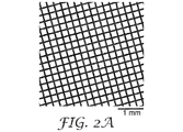
複数の領域(i)、(ii)、及び(iii)は、ランダムに又は擬似ランダムに配列させることができる。ランダムパターン及び疑似ランダムパターンは、これらが、不規則性に関する少なくとも1つの統計的検定を満たすように決定論的因果プロセスを用いるか、又は非決定論的事象を測定するかのいずれかにより見出されるものを含む。例えば、印刷されたランダムパターンは、印刷版よりも小さいサイズスケールで見た場合にはランダムに見えるが、印刷版のサイズを規準として繰り返される。これらのパターンは、領域(i)、(ii)、及び(iii)のサイズ及び位置により、肉眼に見えるものと見えないものとの両方を含む。
In yet another embodiment
(A) A microsphere layer containing a single layer of microspheres, wherein the single layer of microspheres contains a first region substantially free of microspheres and a plurality of randomly dispersed microspheres. A single layer of microspheres comprises a predetermined pattern, comprising (i) a plurality of first regions, (ii) a plurality of second regions, and (iii). Articles comprising these combinations and a microsphere layer comprising at least one of these are described.
The plurality of regions (i), (ii), and (iii) can be arranged randomly or pseudo-randomly. Random and pseudo-random patterns are found either by using deterministic causal processes to satisfy at least one statistical test for irregularity, or by measuring non-deterministic events. including. For example, a printed random pattern looks random when viewed on a size scale smaller than the print plate, but is repeated based on the size of the print plate. These patterns include both visible and invisible, depending on the size and location of the regions (i), (ii), and (iii).
上記の発明の概要は、各実施形態について説明することを意図するものではない。本発明における1つ以上の実施形態の詳細は、下記の説明にも記載されている。他の特徴、目的、及び利点は、本明細書及び特許請求の範囲から明らかとなるであろう。 The outline of the above invention is not intended to explain each embodiment. Details of one or more embodiments of the present invention are also described below. Other features, objectives, and advantages will become apparent from the specification and the claims.
本明細書で用いる場合、用語
「a」、「an」、及び「the」は、内容が別途明示していない限り、複数の指示対象を有する実施形態を包含し、
「及び/又は」は、記載された事例の一方又は両方が生じ得ることを示すのに用いられ、例えば、A及び/又はBは、(A及びB)並びに(A又はB)を含む。
As used herein, the terms "a,""an," and "the" include embodiments with a plurality of referents, unless otherwise stated.
"And / or" is used to indicate that one or both of the described cases can occur, eg, A and / or B include (A and B) and (A or B).
また、本明細書において、端点による範囲の記載は、その範囲内に包含される全ての数を含む(例えば、1〜10は、1.4、1.9、2.33、5.75、9.98などを含む)。 Further, in the present specification, the description of the range by the end points includes all the numbers included in the range (for example, 1 to 10 are 1.4, 1.9, 2.33, 5.75, Including 9.98 etc.).
また、本明細書において、「少なくとも1」の記載は、1以上の全ての数(例えば、少なくとも2、少なくとも4、少なくとも6、少なくとも8、少なくとも10、少なくとも25、少なくとも50、少なくとも100など)を含む。 Further, in the present specification, the description of "at least 1" refers to all numbers of 1 or more (for example, at least 2, at least 4, at least 6, at least 8, at least 10, at least 25, at least 50, at least 100, etc.). include.
装飾的保護表面には多くの消費者用途が見出される。家庭用機器、自動車内装及び塗料、消費者電子デバイス、例えば、ラップトップ及びハンドヘルドデバイスなどは、全て、消費者が、材料のライフサイクルを通して、擦り傷、摩耗(wear及びabrasion)からの相当な保護をもたらしつつ高い美的外見及び美観を保持する材料を好む例である。低光沢度の艶消し面は、これらの美的訴求力ゆえに、多くの消費者の特別な関心の的である。 Many consumer uses are found on decorative protective surfaces. Household equipment, automotive interiors and paints, consumer electronic devices such as laptops and handheld devices all provide considerable protection to consumers from scratches, wear and abrasion throughout the life cycle of the material. It is an example of preference for materials that retain a high aesthetic appearance and aesthetics while bringing. The low gloss matte surface is of particular interest to many consumers because of their aesthetic appeal.
ガラスビーズで構成された耐久性のある積層体及びフィルムが、広く知られている。これらの低光沢度の構造体は、典型的には、構造体に高い耐久性及び装飾性を付与する露出したガラスビーズ表面からなる。典型的には、ビーズが、密に詰められた単層にランダムに位置するように、ビーズがカスケードコーティングされ、又は、適用され、物品表面全体に連続した単層を形成する。米国特許第4,849,265号(Ueda et al.)及び同第5,620,775号(LaPerre)を参照されたい。典型的には、ビーズを物品の表面にランダムに適用して表面全体に連続した単層を形成する際、ビーズサイズ及びサイズ分布に応じて、表面の約72%以上がビーズで被覆される。これらの構造体は耐久性のために硬質ビーズを含み、ビーズは構造体の表面の大部分を被覆するため、物品により、ビーズでコーティングされた構造体の下側に画像(例えば、ロゴ、しるし、画像、色彩豊かなパターン)が配置されていると、視認性の問題が生じ得る。 Durable laminates and films made of glass beads are widely known. These low gloss structures typically consist of exposed glass bead surfaces that impart high durability and decorativeness to the structure. Typically, the beads are cascade coated or applied so that the beads are randomly located in a tightly packed single layer to form a continuous single layer over the entire surface of the article. See U.S. Pat. Nos. 4,849,265 (Ueda et al.) And 5,620,775 (LaPerre). Typically, when beads are randomly applied to the surface of an article to form a continuous single layer over the entire surface, about 72% or more of the surface is covered with beads, depending on the bead size and size distribution. These structures include hard beads for durability, and the beads cover most of the surface of the structure, so the article underneath the bead-coated structure with an image (eg, logo, sign). , Images, colorful patterns) can cause visibility problems.
更に、ポリカーボネートなどの、熱成形可能な基材上の熱成形可能なビーズフィルム(すなわち、熱及び圧力により成形可能なビーズ又は微小球を含むフィルム)が知られているが、高い硬度を維持する一方で、向上した光学的特性(より低いヘイズ及びより高い透明度)を有するものは、以前には記載されていない。 Further, thermoformable bead films (ie, films containing thermoformed beads or microspheres) on thermoformable substrates such as polycarbonate are known, but maintain high hardness. On the other hand, those with improved optical properties (lower haze and higher transparency) have not been previously described.
本出願では、全面被覆よりも少ないビーズの被覆を含み、それでもなお、従来の、連続した単層のビーズでコーティングされた構造体によってもたらされるのと同様の表面の耐久性及び下にある表面の耐摩耗性をもたらす、秩序だった表面を特定した。いくつかの実施形態において、得られる物品は熱成形可能(すなわち、熱及び圧力を用いて成形可能)かつ/又は耐汚染性である。 In this application, the coating of beads is less than the full coverage, yet the surface durability and the underlying surface are similar to those provided by conventional, continuous single layer bead coated structures. We have identified an ordered surface that provides abrasion resistance. In some embodiments, the resulting article is thermoformed (ie, moldable using heat and pressure) and / or stain resistant.
本明細書において、微小球のパターンを有する露出表面を有し、表面が機械的耐久性(例えば、耐摩耗性及び/又は鉛筆硬度)を有し、透過視認性が向上し、かつ/又は微小球の所定のパターンを有さない同様の構造体よりも安価である、構造体を開示する。これらの構造体は、一実施形態において、表面の特性を変更するために表面に適用される場合がある。 In the present specification, it has an exposed surface having a pattern of microspheres, the surface has mechanical durability (eg, abrasion resistance and / or pencil hardness), transmission visibility is improved, and / or micro. Disclosed are structures that are cheaper than similar structures that do not have a given pattern of spheres. These structures may, in one embodiment, be applied to the surface to alter the properties of the surface.
一実施形態において、本開示の物品は再帰反射性ではない。物品の再帰反射性は、その再帰反射係数(coefficient of retroreflectivity:Ra)
Ra=Er*d2/Es*A
[式中、
Er=受光器上の照度
Es=試験片の位置の、入射光線に対して垂直な平面上の照度(Erと同じ単位で測定)
d=試験片からプロジェクタまでの距離
A=試験表面の面積]
によって表すことができる。
再帰反射係数(Ra)は、米国特許第3,700,305号(Bingham)に更に記載されている。一実施形態において、本開示の物品は、ASTM E810−03(2013)「Standard Test Method for Coefficient of Retroreflection of Retroreflective Sheeting Utilizing the Coplanar Geometry」に従い、0.2°の観察角及び5°の導入角で測定される再帰反射の係数が、10カンデラ/ルクス/平方メートル以下、5カンデラ/ルクス/平方メートル以下、1カンデラ/ルクス/平方メートル以下、0.5カンデラ/ルクス/平方メートル以下、又は0.3カンデラ/ルクス/平方メートル以下である。
In one embodiment, the articles of the present disclosure are not retroreflective. The retroreflectivity of an article is its coefficient of retroreflectivity ( Ra ).
R a = Er * d 2 / E s * A
[During the ceremony,
Position of E r = photoreceiver on the illuminance E s = specimen (measured in the same units as E r) illuminance on a plane perpendicular to the incident light
d = distance from the test piece to the projector A = area of the test surface]
Can be represented by.
The retroreflection coefficient ( Ra ) is further described in US Pat. No. 3,700,305 (Bingham). In one embodiment, the article of the present disclosure is in accordance with ASTM E810-03 (2013) "Standard Test Method for Cofficient of Retroreflection of Retroreflective Sheeting Angle" introduced in Candela 0.2. The measured retroreflection coefficient is 10 candela / lux / square meter or less, 5 candela / lux / square meter or less, 1 candela / lux / square meter or less, 0.5 candela / lux / square meter or less, or 0.3 candela / lux. / Less than square meters.
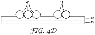
図1は、本開示における物品の一実施形態の断面図である。物品10は、微小球11の単層を含む微小球層を含み、複数の微小球が、ビーズ結合層12中に部分的に埋め込まれている。一実施形態において、物品は、ビーズ結合層に埋め込まれた複数の微小球を含み、ビーズ結合層は基材層上に配置されている。このような構造体を、ビーズ結合層12が基材層14上に配置されている図1に示す。いくつかの実施形態において、物品は、後述の通り、追加の層をビーズ結合層と基材との間に含む場合がある。
FIG. 1 is a cross-sectional view of an embodiment of the article in the present disclosure.
基材層 Base material layer
基材層は、処理中及び取り扱い中に、ビーズ結合層及び埋め込まれた微小球に、追加の支持をもたらすことができる。あるいは又は更に、基材層は、得られる物品を摩耗、擦り傷などから保護する表面であってもよい。 The substrate layer can provide additional support to the bead binding layer and the embedded microspheres during treatment and handling. Alternatively, or further, the substrate layer may be a surface that protects the resulting article from abrasion, scratches, and the like.
好適な基材層の例としては、これらに限定されるものではないが、布地(ナイロン、ポリエステルなどの合成、非合成、織布及び不織布を含む);ビニルコーティングした布地、ポリウレタンコーティングした布地などのポリマーコーティングした布地;革;金属;塗料コーティングした金属;紙;ポリエチレンテレフタレート、アクリル樹脂、ポリカーボネート、ポリウレタン、天然及び合成ゴムなどのエラストマーなどのポリマーフィルム又はシートのうちの少なくとも1つから選択されるもの;並びに、例えば、ポリウレタン発泡体、ポリエチレン発泡体、発泡ゴムなどを含む、連続気泡発泡体及び独立気泡発泡体が挙げられる。基材は、例えば、衣類物品又は履物;自動車、船舶、又は他の車両におけるシートの被覆材;自動車、船舶、又は他の車両の本体;整形外科デバイス;電子デバイス(例えば、トラックパッド、及び外面カバーを含む)、ハンドヘルドデバイス、家庭用機器;スポーツ用品などの形態であってもよい。 Examples of suitable substrate layers include, but are not limited to, fabrics (including synthetic, non-synthetic, woven and non-woven fabrics such as nylon and polyester); vinyl coated fabrics, polyurethane coated fabrics and the like. Polymer coated fabrics; leather; metals; paint coated metals; paper; selected from at least one of polymer films or sheets such as polyethylene terephthalates, acrylic resins, polycarbonates, polyurethanes, and elastomers such as natural and synthetic rubbers. Things; as well as open cell foams and closed cell foams, including, for example, polyurethane foams, polyethylene foams, foamed rubbers and the like. Substrates are, for example, clothing articles or footwear; seat coverings in automobiles, ships, or other vehicles; bodies of automobiles, ships, or other vehicles; orthopedic devices; electronic devices (eg, trackpads, and exterior surfaces). (Including covers), handheld devices, household equipment; may be in the form of sporting goods and the like.
一実施形態において、基材層は、熱成形可能な材料であり、得られる物品の熱成形を可能とすることができる。熱成形可能な材料は、熱成形温度よりも低いガラス転移温度を有さなくてはならない。一実施形態において、基材は、ガラス転移温度が60℃以上、70℃以上、又は80℃以上、かつ160℃以下、150℃以下、140℃以下、130℃以下、120℃以下、又は110℃以下である材料を含む。 In one embodiment, the substrate layer is a thermoformed material and can be thermoformed of the resulting article. The thermoformed material must have a glass transition temperature lower than the thermoforming temperature. In one embodiment, the substrate has a glass transition temperature of 60 ° C. or higher, 70 ° C. or higher, or 80 ° C. or higher, and 160 ° C. or lower, 150 ° C. or lower, 140 ° C. or lower, 130 ° C. or lower, 120 ° C. or lower, or 110 ° C. Includes the following materials:
一実施形態において、基材は、厚さが少なくとも5、10、20、25、50又は75マイクロメートルである。一実施形態において、基材は、厚さが最大25mm又は50mmである。 In one embodiment, the substrate is at least 5, 10, 20, 25, 50 or 75 micrometers thick. In one embodiment, the substrate has a maximum thickness of 25 mm or 50 mm.
ビーズ結合層 Bead binding layer
複数の微小球は、ビーズ結合層を介し、基材の上部に適切に保持される。ビーズ結合層は、典型的には、有機ポリマー材料である。有機ポリマー材料は、微小球に対して良好な接着性を呈する。ビーズ結合層を微小球の表面上に配置させるためのプロセスウィンドウ内に適合している限り、微小球用の接着促進剤を、ビーズ結合層自体に直接加えることも可能である。 The plurality of microspheres are properly held on the upper part of the substrate via the bead binding layer. The bead binding layer is typically an organic polymer material. The organic polymer material exhibits good adhesion to microspheres. Adhesion promoters for microspheres can also be added directly to the bead-binding layer itself, as long as it fits within the process window for placing the bead-binding layer on the surface of the microspheres.
ビーズ結合層において有用な材料としては、これらに限定されるものではないが、ポリウレタン、ポリエステル、アクリル酸及びメタクリル酸エステルポリマー及びコポリマー、エポキシ、ポリ塩化ビニルポリマー及びコポリマー、ポリ酢酸ビニルポリマー及びコポリマー、ポリアミドポリマー及びコポリマー、フッ素含有ポリマー及びコポリマー、シリコーン、シリコーン含有コポリマー、ネオプレンなどの合成及び天然ゴムを含むエラストマー、アクリロニトリルブタジエンコポリマー、ポリマーマトリックス複合体、並びにこれらの組み合わせのうちの少なくとも1つから選択されるものが挙げられる。いくつかの実施形態において、ポリマーマトリックス複合体は、樹脂中のナノ粒子、樹脂中の繊維などを含む。組み合わせは、相互貫入ネットワーク、二重硬化系などの材料の任意の組み合わせを含み得る。 Useful materials in the bead bonding layer include, but are not limited to, polyurethanes, polyesters, acrylic acids and methacrylic acid ester polymers and copolymers, epoxys, polyvinyl chloride polymers and copolymers, polyvinyl acetate polymers and copolymers. Selected from polyamide polymers and copolymers, fluoropolymers and copolymers, silicones, silicone-containing copolymers, elastomers containing synthetic and natural rubbers such as neoprene, acrylonitrile butadiene copolymers, polymer matrix composites, and at least one of these combinations. There are things. In some embodiments, the polymer matrix complex comprises nanoparticles in the resin, fibers in the resin, and the like. Combinations can include any combination of materials such as mutual intrusive networks, double hardening systems and the like.
本開示の一実施形態において、本開示のビーズ結合層が、(i)フッ素含有ポリマーを含む樹脂と、(ii)直鎖状樹脂と、(iii)低架橋密度を有する樹脂と、(iv)高架橋密度を有する樹脂と、(v)これらの組み合わせ及びブレンドと、のうちの少なくとも1つを含む。本明細書で用いる場合、樹脂は、ポリマー、特に、金属のフレークなどの顔料又は着色剤、レオロジー改質剤、UV安定剤、抗酸化剤などの添加剤を含む固体又は高粘度の材料を指す。このような樹脂をビーズ結合層に用いることにより、耐汚染性及び/又は熱成形能を物品に付与することができる。 In one embodiment of the present disclosure, the bead binding layer of the present disclosure comprises (i) a resin containing a fluorine-containing polymer, (ii) a linear resin, (iii) a resin having a low crosslink density, and (iv). It comprises a resin having a high crosslink density and (v) at least one of these combinations and blends. As used herein, resin refers to a solid or viscous material containing polymers, in particular pigments or colorants such as metal flakes, rheology modifiers, UV stabilizers, antioxidants and other additives. .. By using such a resin for the bead binding layer, stain resistance and / or thermoforming ability can be imparted to the article.
例えば、高架橋密度を有する樹脂は、得られる物品に耐汚染性を付与することができる。低架橋密度を有する直鎖状樹脂又は樹脂は熱成形させることができ、その一方で、フッ素含有ポリマー(例えばTHVなどの直鎖状フッ素含有ポリマーなど)を加えて耐汚染性を付与することができる。例えば、二重硬化系において、低架橋密度を有し、場合により、フッ素化ポリマーを含む樹脂を熱成形し、続いて架橋工程を用い、高架橋密度を有する樹脂を生成させ、耐汚染性をもたらすことができる。 For example, a resin having a viaduct density can impart stain resistance to the obtained article. A linear resin or resin having a low crosslink density can be thermoformed, while a fluorine-containing polymer (such as a linear fluorine-containing polymer such as THV) can be added to impart stain resistance. can. For example, in a double-curing system, a resin having a low crosslink density and, in some cases, containing a fluorinated polymer is thermoformed and then a crosslinking step is used to produce a resin with a high crosslink density, resulting in stain resistance. be able to.
一実施形態において、ビーズ結合層樹脂はフッ素含有ポリマーを含み、物品に耐汚染性を付与することができる。一実施形態において、耐汚染特性は、ビーズ結合層のフッ素含有ポリマー中におけるフッ素原子の量及び位置に関連している場合がある。例えば、フッ素原子がポリマー主鎖(すなわち、ポリマーの主鎖)に沿って位置する場合、耐汚染性が向上する場合がある。ポリマー中に存在するフッ素原子の量は、重合性鎖において、含まれるモノマーの重量比及び各モノマーのフッ素重量含量の両方を、重合性鎖から原子一個分だけ離れた原子上に存在するフッ素原子を含めて考慮することにより、計算することができる。一例として、テトラフルオロエチレン、ヘキサフルオロプロピレン、及びフッ化ビニリデンの重量比10:40:50のコポリマーは、67.7%の主鎖フッ素含量を有し得る。これは以下のように計算した。
テトラフルオロエチレン:C2F4、分子量100.01、モノマーのフッ素含量76.0%、重量比10%;
ヘキサフルオロプロピレン:C3F6、分子量150.02、モノマーのフッ素含量76.0%、重量比40%;
フッ化ビニリデン:C2H2F2、分子量64.03、モノマーのフッ素含量59.3%、重量比50%。
(0.1×0.76)+(0.4×0.76)+(0.5×0.593)]×100=67.7%。
In one embodiment, the bead binding layer resin comprises a fluorine-containing polymer, which can impart stain resistance to the article. In one embodiment, the stain resistance property may be related to the amount and position of fluorine atoms in the fluorine-containing polymer of the bead bond layer. For example, if the fluorine atom is located along the polymer backbone (ie, the polymer backbone), stain resistance may be improved. The amount of fluorine atoms present in the polymer is such that in the polymerizable chain, both the weight ratio of the monomers contained and the fluorine weight content of each monomer are separated from the polymerizable chain by one atom. It can be calculated by considering including. As an example, a copolymer of tetrafluoroethylene, hexafluoropropylene, and vinylidene fluoride in a weight ratio of 10:40:50 may have a main chain fluorine content of 67.7%. This was calculated as follows.
Tetrafluoroethylene: C 2 F 4 , molecular weight 100.01, monomer fluorine content 76.0%,
Hexafluoropropylene: C 3 F 6 , molecular weight 150.02, monomer fluorine content 76.0%, weight ratio 40%;
Vinylidene fluoride: C 2 H 2 F 2 , molecular weight 64.03, fluorine content of monomer 59.3%,
(0.1 × 0.76) + (0.4 × 0.76) + (0.5 × 0.593)] × 100 = 67.7%.
この計算は、ヘキサフルオロプロピレンのトリフルオロメチル基上のフッ素原子を含むが、これはこのフッ素原子がヘキサフルオロプロピレンモノマーの重合性鎖から原子一個分だけ離れているからである。 This calculation includes a fluorine atom on the trifluoromethyl group of hexafluoropropylene because this fluorine atom is separated from the polymerizable chain of the hexafluoropropylene monomer by one atom.
本開示のいくつかの実施形態において、フッ素含有ポリマーのポリマー主鎖に沿ったフッ素含有量は、少なくとも15重量%、20重量%、25重量%、27重量%、30重量%、又は40重量%であり、最大76重量%、72重量%又は70重量%以下である。 In some embodiments of the present disclosure, the fluorine content along the polymer backbone of the fluorine-containing polymer is at least 15% by weight, 20% by weight, 25% by weight, 27% by weight, 30% by weight, or 40% by weight. The maximum is 76% by weight, 72% by weight, or 70% by weight or less.
所望のフッ素含量を有するフルオロポリマー含有樹脂であったとしても、これらの樹脂は、高温高湿でイエローマスタードなどの汚染性の高い物質に対して所望のレベルの耐汚染性を呈さない場合がある。理論による束縛を望むものではないが、フッ素原子がペンダント側鎖又は末端基に唯一若しくは主として存在する材料は、本開示の一実施形態における物品の所望の耐汚染特性を呈さないものと考えられる。これに対し、フッ素原子が、ポリマー主鎖に、又は、主鎖から炭素1つ分離れた範囲内に、唯一若しくは主として存在する材料は、高温高湿でイエローマスタードに対して適切な耐汚染性をもたらすことができる。 Even if the fluoropolymer-containing resins have the desired fluorine content, these resins may not exhibit the desired level of stain resistance against highly contaminating substances such as yellow mustard at high temperatures and humidity. .. Although not theoretically bound, it is believed that a material in which a fluorine atom is uniquely or predominantly present in the pendant side chain or end group does not exhibit the desired stain resistance properties of the article in one embodiment of the present disclosure. On the other hand, the material in which the fluorine atom is present only or mainly in the polymer main chain or in the range separated by one carbon from the main chain has appropriate stain resistance to yellow mustard at high temperature and high humidity. Can bring.
いくつかの実施形態において、特定のガラス転移温度(Tg)を有するフッ素含有ポリマーが、本開示において有用である。理論に束縛されるわけではないが、Tgが高いほど、イエローマスタードの汚染に対して耐性がより高いものと考えられる。例えば、いくつかの実施形態において、Tgが少なくとも60℃、70℃、又は80℃であるフッ素含有ポリマーが、本開示において有用である。いくつかの実施形態において、Tgが150℃以下、又は100℃以下のフッ素含有ポリマーが、本開示において有用である。 In some embodiments, a fluorine-containing polymer having a particular glass transition temperature (Tg) is useful in the present disclosure. Without being bound by theory, it is believed that the higher the Tg, the more resistant to yellow mustard contamination. For example, in some embodiments, a fluorine-containing polymer having a Tg of at least 60 ° C, 70 ° C, or 80 ° C is useful in the present disclosure. In some embodiments, fluorine-containing polymers with a Tg of 150 ° C or lower, or 100 ° C or lower, are useful in the present disclosure.
ビーズ結合層において有用なフッ素含有ポリマーとしては、これらに限定されるものではないが、以下のもの、すなわち、フルオロオレフィン及びフルオロウレタンのうちの少なくとも1つから選択されるものが挙げられる。フルオロオレフィンとしては、エラストマー性フルオロオレフィンポリマー、熱可塑性フルオロオレフィンポリマー、多官能性アクリレート又は多官能性アミンにより架橋されたエラストマー性フルオロオレフィンポリマー、及び多官能性アミンにより架橋された熱可塑性フルオロオレフィンポリマーが挙げられる。フルオロウレタンとしては、架橋されたフッ素化ポリウレタンが挙げられる。これらの材料の任意の組み合わせもまた、これらが互いに混和性である限り用いることができる。いくつかの実施形態において、本開示において有用なフッ素含有ポリマーは、例えば、塩素などの他のハロゲンも含み得る。本開示において有用な例示的なフッ素含有ポリマーとしては、クロロトリフルオロエチレン(CTFE)が挙げられる。これらの材料の任意の組み合わせもまた、これらが互いに混和性である限り用いることができる。 Fluorine-containing polymers useful in the bead-bonded layer include, but are not limited to, the following, i.e., those selected from at least one of fluoroolefins and fluorourethanes. Fluoroolefins include an elastomeric fluoroolefin polymer, a thermoplastic fluoroolefin polymer, an elastomeric fluoroolefin polymer crosslinked with a polyfunctional acrylate or a polyfunctional amine, and a thermoplastic fluoroolefin polymer crosslinked with a polyfunctional amine. Can be mentioned. Examples of fluorourethane include crosslinked fluorinated polyurethane. Any combination of these materials can also be used as long as they are miscible with each other. In some embodiments, the fluorine-containing polymers useful in the present disclosure may also include other halogens, such as chlorine. Exemplary fluorine-containing polymers useful in the present disclosure include chlorotrifluoroethylene (CTFE). Any combination of these materials can also be used as long as they are miscible with each other.
有用なエラストマー性フルオロオレフィンポリマーの例としては、これらに限定されるものではないが、テトラフルオロエチレン、ヘキサフルオロプロピレン、及びフッ化ビニリデンの臭素含有コポリマー、例えば、商標名3M DYNEON PEROXIDE CURE FLUOROELASTOMER FPO 3740で3M Company(St.Paul,MN)より入手可能であるものなど、並びに超低粘度フルオロポリマー、例えば、商標名3M DYNEON FLUOROELASTOMER E−20575で3M Company(St.Paul,MN)より試験的又は開発中の製品として入手されるものなどが挙げられる。有用な熱可塑性フルオロオレフィンポリマーの例としては、これらに限定されるものではないが、テトラフルオロエチレン、ヘキサフルオロプロピレン、及びフッ化ビニリデンのコポリマー、例えば、商標名3M DYNAMAR POLYMER PROCESSING ADDITIVE FX 5912で3M Company(St.Paul,MN)より入手可能なものなどが挙げられる。 Examples of useful elastomeric fluoroolefin polymers include, but are not limited to, bromine-containing copolymers of tetrafluoroethylene, hexafluoropropylene, and vinylidene fluoride, eg, 3M DYNEON PEROXIDE CURE FLUOROELASTOMER FPO 3740. Trial or development from 3M Company (St. Paul, MN) with ultra-low viscosity fluoropolymers such as those available from 3M Company (St. Paul, MN) and, for example, the brand name 3M DYNEON FLUOROELASTOMER E-20575. Examples include those obtained as products inside. Examples of useful thermoplastic fluoroolefin polymers are, but are not limited to, copolymers of tetrafluoroethylene, hexafluoropropylene, and vinylidene fluoride, such as 3M with the brand name 3M DYNAMAR POLYMER PROCESSING ADDITIVE FX 5912. Examples include those available from Company (St. Paul, MN).
フッ素含有ポリマーは、ビーズ結合層を形成する樹脂中で用い、架橋されてもよい。有用な共架橋されたフルオロポリマーの例としては、これらに限定されるものではないが、多官能性アクリレートと共反応させたエラストマー性フルオロオレフィン、例えば、商標名SARTOMER SR 344でSartomer USA,LLC(Exton,PA)より入手可能なペンタエリスリトールトリアクリレートなどが挙げられ、また、商標名SARTOMER SR 351HでSartomer USA,LLC(Exton,PA)より入手可能なトリメチロールプロパントリアクリレートを用いてもよい。アミンにより架橋された有用なフルオロポリマーの例としては、これらに限定されるものではないが、多官能性一級アミンと反応させた熱可塑性フルオロオレフィン、例えば、商標名JEFFAMINE T403でHuntsman Corporation(The Woodlands,TX)より入手可能なもの、及びポリエーテルイミン、例えば、コード番号32034100でThermo Fisher Scientific(Minneapolis,MN)の子会社ACROS Organicsより入手されるものなどが挙げられる。フルオロウレタンの有用な非限定的な例としては、多官能性脂肪族イソシアネート樹脂系のヘキサメチレンジイソシアネート(HDI)の反応から誘導されるもの、例えば、商標名DESMODUR N3300AでBayer Materials Science LLC(Pittsburgh,PA)より入手可能なものなど、及びフッ素化ポリドロキシ(polydroxy)含有ポリマー、例えば、商標名ZEFFLE GK 570でDaikin America(Orangeburg,NY)より入手可能なものなどが挙げられる。いくつかの実施形態において、フッ素含有ポリマーの有用な非限定的な例としては、フルオロエチレンとビニルエーテルとの固体のコポリマーから誘導されるもの、例えば、商標名LUMIFLON LF−200FでAGC Chemicals America(Exton,PA)より入手可能なものなどが挙げられる。これらのフッ素化ポリヒドロキシポリマーは、例えばイソシアネートによって架橋することができる。一実施形態において、物品の耐汚染性は、高架橋密度を有する樹脂製のビーズ結合層を用いることによって実現することができる。本明細書で用いる場合、高架橋密度は、米国特許第8,420,217号(Johnson)に説明されている計算を用いる、高い系の官能性を有する樹脂を指す。 The fluorine-containing polymer may be used in the resin forming the bead binding layer and crosslinked. Examples of useful co-crosslinked fluoropolymers include, but are not limited to, elastomeric fluoroolefins co-reacted with polyfunctional acrylates, such as the Sartomer USA, LLC under the trade name SARTOMER SR 344. Examples thereof include pentaerythritol triacrylate available from Exton, PA), and trimethylolpropane triacrylate available from Saltomer USA, LLC (Exton, PA) under the trade name SARTOMER SR 351H may be used. Examples of useful fluoropolymers crosslinked with amines include, but are not limited to, thermoplastic fluoroolefins reacted with polyfunctional primary amines, such as Huntsman Corporation (The Woodlands) under the trade name JEFFAMINE T403. , TX), and those obtained from polyether imine, eg, ACROS Organics, a subsidiary of Thermo Fisher Scientific (Minneapolys, MN) with code number 32034100. Useful non-limiting examples of fluorourethanes are those derived from the reaction of a polyfunctional aliphatic isocyanate resin-based hexamethylene diisocyanate (HDI), such as Bayer Materials Science LLC (Pittsburg, under the trade name DESMODUR N3300A,). Examples include those available from PA) and polymers containing fluorinated polydroxy, such as those available from Daikin America (Orangeburg, NY) under the trade name ZEFFLE GK 570. In some embodiments, useful non-limiting examples of fluorine-containing polymers are those derived from solid copolymers of fluoroethylene and vinyl ether, such as AGC Chemicals America (Exton) under the trade name LUMIFLON LF-200F. , PA). These fluorinated polyhydroxy polymers can be crosslinked, for example, with isocyanates. In one embodiment, stain resistance of the article can be achieved by using a resin bead binding layer having a viaduct density. As used herein, viaduct density refers to a resin with high functionality using the calculations described in US Pat. No. 8,420,217 (Johnson).
「系の官能性」は、縮合における反応性基の当量の総モルを、2つの構成成分の総モルで除したものと定義される。例えば、ポリウレタンの生成においては、ヒドロキシル基とイソシアネート基との当量の総モルが、ポリオールと多官能性イソシアネートとの総モルで除される。ポリウレアの生成においては、アミン基とイソシアネート基との当量の総モルが、ポリアミンと多官能性イソシアネートとの総モルで除される。高架橋密度を有する樹脂を得るためには、系の官能性が2.4超、3.0超、4.0超、5.0超、又は10超でなくてはならず、これは、樹脂が実質的な架橋を有することを意味する。系の官能性が2.0以下である場合、架橋はほとんど又は全くもたらされず、材料は典型的には熱成形可能である。系の官能性が上記の範囲の間にある場合、樹脂は軽度に架橋されている。典型的には、より高い系の官能性により、より高い架橋及びより硬い系がもたらされる。本明細書で用いる場合、「当量のモル」は、官能基のモルを指す。したがって、ポリオールの場合、当量のモルは水酸基(OH)の当量のモルであり、イソシアネートの場合、イソシアネート基(NCO)のモルである。例えば、ジオール又はジイソシアネートの場合、当量のモルはそれぞれジオール又はジイソシアネートのモルの2倍に等しくなる。同様に、トリオールの場合、当量のモルはトリオールのモルの3倍に等しくなる。特定のポリオールについての「等価物のモル分率」は、ポリオールの組み合わせにおける全てのポリオールについての当量のモルで除されたその特定のポリオールに対する当量のモルの比率である。この定義に基づくと、組み合わせにおける全てのポリオールに対する当量のモル分率の合計は、1である。架橋剤は、2.0超の官能性、例えば、少なくとも3の官能性を有する。いくつかの実施形態において、架橋剤は、より高い官能性、例えば、4を有する場合がある。いくつかの実施形態において、架橋剤は、低分子量トリオール、例えば、グリセロール(すなわち、プロパン−1,2,3−トリオール)である。他の例示的な架橋剤としては、トリメチロールプロパン、1,2,6−ヘキサントリオール、及びトリエタノールアミンが挙げられる。いくつかの実施形態において、架橋剤の組み合わせが用いられる場合がある。いくつかの実施形態において、架橋剤はトリイソシアネートである。 "System functionality" is defined as the total mole of reactive group equivalents in condensation divided by the total moles of the two constituents. For example, in the formation of polyurethane, the total mole of equivalent hydroxyl and isocyanate groups is divided by the total mole of polyol and polyfunctional isocyanate. In the formation of polyurea, the total moles of equivalents of amine and isocyanate groups are divided by the total moles of polyamines and polyfunctional isocyanates. In order to obtain a resin with a high crosslink density, the functionality of the system must be greater than 2.4, greater than 3.0, greater than 4.0, greater than 5.0, or greater than 10, which is the resin. Means that has a substantial crosslink. If the functionality of the system is 2.0 or less, no cross-linking is provided and the material is typically thermoformable. If the functionality of the system is within the above range, the resin is mildly crosslinked. Typically, the higher functionality of the system results in higher cross-linking and a harder system. As used herein, "equivalent mole" refers to a mole of a functional group. Therefore, in the case of a polyol, the equivalent mole is the equivalent molar of the hydroxyl group (OH), and in the case of isocyanate, it is the molar of the isocyanate group (NCO). For example, in the case of diols or diisocyanates, the equivalent moles are equal to twice the moles of diols or diisocyanates, respectively. Similarly, in the case of triol, the equivalent mole is equal to three times the mole of triol. The "equivalent mole fraction" for a particular polyol is the ratio of equivalent moles to that particular polyol divided by the equivalent moles for all polyols in a combination of polyols. Based on this definition, the sum of the mole fractions of equivalents for all polyols in the combination is 1. The cross-linking agent has a functionality of more than 2.0, eg, at least 3. In some embodiments, the cross-linking agent may have higher functionality, eg, 4. In some embodiments, the cross-linking agent is a low molecular weight triol, eg, glycerol (ie, propane-1,2,3-triol). Other exemplary crosslinkers include trimethylolpropane, 1,2,6-hexanetriol, and triethanolamine. In some embodiments, a combination of cross-linking agents may be used. In some embodiments, the cross-linking agent is triisocyanate.
系の官能性が2.0超〜2.15である場合、系の官能性が2.4超であるものよりも架橋性が低い。より高い官能性を有する系は、より架橋されている。高い系の官能性と、1000未満のイソシアネート及び/又はポリオールの当量との組み合わせが、剛性の用途には好ましい。 When the functionality of the system is more than 2.0 to 2.15, the crosslinkability is lower than that of the system having the functionality of more than 2.4. Systems with higher functionality are more crosslinked. A combination of high functionality and equivalent of less than 1000 isocyanates and / or polyols is preferred for rigid applications.
概して、イソシアネート基の当量のモルへの、水酸基の当量のモルに対する比(NCO/OH)は約1、例えば、0.7〜1.3(両端の値を含む)、いくつかの実施形態においては、0.9〜1.1(両端の値を含む)でなくてはならない。NCO/OH比が1超の場合、架橋密度が増加し、より高い硬度と、より低い伸長とをもたらす。NCO/OH比が1未満の場合、系はより低い架橋密度を有し、より軟質の系と、より高い伸長とをもたらす。したがって、NCO/OHの正確な比を調整し、所望の機械的特性を得ることができる。更に、NCO/OH比を低下させると、系をより親水性とする傾向があり、典型的には、水蒸気透過性がより高くなり、「透湿性の」構造から利益を得る用途において望ましい場合がある。 In general, the ratio of hydroxyl groups to molar equivalents of isocyanate groups to moles (NCO / OH) is about 1, eg, 0.7-1.3 (including values at both ends), in some embodiments. Must be 0.9 to 1.1 (including the values at both ends). When the NCO / OH ratio is greater than 1, the crosslink density increases, resulting in higher hardness and lower elongation. When the NCO / OH ratio is less than 1, the system has a lower crosslink density, resulting in a softer system and higher elongation. Therefore, the exact ratio of NCO / OH can be adjusted to obtain the desired mechanical properties. In addition, lowering the NCO / OH ratio tends to make the system more hydrophilic, typically more water vapor permeable, which may be desirable in applications that benefit from "breathable" structures. be.
いくつかの実施形態において、完全な架橋を確保するには、1超のNCO/OH比を用いるのが望ましい場合がある。例えば、ポリオールは、典型的には吸湿性であり、系内に水を運搬することができる。この水は、利用可能なNCO部位と迅速に反応する傾向があり、NCO部位が、ポリオールの水酸基との架橋に利用できなくなってしまう。いくつかの実施形態において、少なくとも1.02のNCO/OH比(例えば、1.02〜1.07(両端の値を含む))、また、いくつかの実施形態においては、少なくとも1.04(例えば、1.04〜1.06(両端の値を含む))が用いられる場合がある。 In some embodiments, it may be desirable to use an NCO / OH ratio greater than 1 to ensure complete cross-linking. For example, polyols are typically hygroscopic and can carry water into the system. This water tends to react rapidly with the available NCO moieties, making the NCO moieties unavailable for cross-linking with the hydroxyl groups of the polyol. In some embodiments, an NCO / OH ratio of at least 1.02 (eg, 1.02 to 1.07 (including values at both ends)), and in some embodiments, at least 1.04 (eg, values at both ends). For example, 1.04 to 1.06 (including the values at both ends) may be used.
高架橋密度を有する樹脂は、重合性不飽和結合又はエポキシ基をこれらの分子内に有するプレポリマー、オリゴマー及び/又はモノマーの好適な混合物を含む電離放射線硬化性組成物から誘導することができる。 Resins with high cross-linking densities can be derived from ionizing radiation curable compositions containing suitable mixtures of prepolymers, oligomers and / or monomers having polymerizable unsaturated bonds or epoxy groups within these molecules.
プレポリマー及びオリゴマーとしては、不飽和ジカルボン酸と多価アルコールとの縮合物などの不飽和ポリエステル;ポリエステルメタアクリレート、ポリエーテルメタクリレート、ポリオールメタクリレート、及びメラミンメタクリレートなどのメタクリレート;ポリエステルアクリレート、エポキシアクリレート、ウレタンアクリレート、ポリエーテルアクリレート、ポリオールアクリレート、及びメラミンアクリレートなどのアクリレート;並びにカチオン重合性エポキシ化合物が挙げられる。 Prepolymers and oligomers include unsaturated polyesters such as condensates of unsaturated dicarboxylic acids and polyhydric alcohols; methacrylates such as polyester methacrylates, polyether methacrylates, polyol methacrylates, and melamine methacrylates; polyester acrylates, epoxy acrylates, urethanes. Acrylates such as acrylates, polyether acrylates, polyol acrylates, and melamine acrylates; as well as cationically polymerizable epoxy compounds.
例えば、ウレタンアクリレートとしては、例えば、ポリエーテルジオールをヒドロキシル含有アクリレート及びジイソシアネートと反応させることによって調製される、下記の一般式:
CH2=C(R1)−COOCH2CH2−OCONH−X−NHCOO−[−CH(R2)−(CH2)n−O−]m−CONH−X−NHCOO−CH2CH2OCOC(R1)=CH2
[式中、R1及びR2はそれぞれ独立して水素原子又はメチル基を表し、Xはジイソシアネート残基を表し、nは1〜3の整数であり、mは6〜60の整数である]で表されるポリエーテルウレタン(メタ)アクリレートが挙げられる。
For example, the urethane acrylate is prepared, for example, by reacting a polyether diol with a hydroxyl-containing acrylate and a diisocyanate, and has the following general formula:
CH 2 = C (R 1 ) -COOCH 2 CH 2- OCONH-X-NHCOO- [-CH (R 2 )-(CH 2 ) n- O-] m- CONH-X-NHCOO-CH 2 CH 2 OCOC (R 1 ) = CH 2
[In the formula, R 1 and R 2 each independently represent a hydrogen atom or a methyl group, X represents a diisocyanate residue, n is an integer of 1 to 3, and m is an integer of 6 to 60]. Examples thereof include polyether urethane (meth) acrylate represented by.
ポリエーテルウレタン(メタ)アクリレートとして使用可能なジイソシアネートとしては、例えば、イソホロンジイソシアネート、ジシクロヘキシルメタンジイソシアネート、ヘキサメチレンジイソシアネート、ジフェニルメタンジイソシアネート、及びトリレンジイソシアネートが挙げられる。ポリエーテルジオールとしては、ポリオキシプロピレングリコール、ポリオキシエチレングリコール、及びポリオキシテトラメチレングリコールが挙げられ、これらのポリエーテルジオールは、数平均分子量が500〜3,000g/モルである。 Examples of the diisocyanate that can be used as the polyether urethane (meth) acrylate include isophorone diisocyanate, dicyclohexylmethane diisocyanate, hexamethylene diisocyanate, diphenylmethane diisocyanate, and tolylene diisocyanate. Examples of the polyether diol include polyoxypropylene glycol, polyoxyethylene glycol, and polyoxytetramethylene glycol, and these polyether diols have a number average molecular weight of 500 to 3,000 g / mol.
電離放射線硬化性樹脂の形成に使用可能なモノマーとしては、スチレン、例えば、スチレン及びα−メチルスチレンなど;アクリル酸エステル、例えば、メチルアクリレート、2−エチルヘキシルアクリレート、メトキシエチルアクリレート、ブトキシエチルアクリレート、ブチルアクリレート、メトキシブチルアクリレート、及びフェニルアクリレートなど;メタクリル酸エステル、例えば、メチルメタクリレート、エチルメタクリレート、プロピルメタクリレート、メトキシエチルメタクリレート、エトキシメチルメタクリレート、フェニルメタクリレート、及びラウリルメタクリレートなど;不飽和置換酸の置換アミノアルコールエステル、例えば、2−(N,N−ジエチルアミノ)エチルアクリレート、2−(N,N−ジメチルアミノ)エチルメタクリレート、2−(N,N−ジベンジルアミノ)メチルアクリレート、及び2−(N,N−ジエチルアミノ)プロピルアクリレートなど;不飽和カルボン酸アミド、例えば、アクリルアミド及びメタクリルアミドなど;エチレングリコールジアクリレート、プロピレングリコールジアクリレート、ネオペンチルグリコールジアクリレート、1,6−ヘキサンジオールジアクリレート、及びトリエチレングリコールジアクリレートなどの化合物;多官能性化合物、例えば、ジプロピレングリコールジアクリレート、エチレングリコールジアクリレート、プロピレングリコールジメタクリレート、及びジエチレングリコールジメタクリレート;並びに/又は、2つ以上のチオール基をその分枝中に有するポリチオール化合物、例えば、トリメチロールプロパントリチオグリコレート、トリメチロールプロパントリチオプロピレート、及びペンタエリスリトールテトラチオグリコールなどが挙げられる。 Monomers that can be used to form the ionizing radiation curable resin include styrene, such as styrene and α-methylstyrene; acrylic acid esters such as methyl acrylate, 2-ethylhexyl acrylate, methoxyethyl acrylate, butoxyethyl acrylate, butyl. Acrylate, methoxybutyl acrylate, phenylacrylate, etc .; methacrylic acid esters such as methyl methacrylate, ethyl methacrylate, propyl methacrylate, methoxyethyl methacrylate, ethoxymethyl methacrylate, phenyl methacrylate, and lauryl methacrylate; substituted amino alcohols of unsaturated substituents. Esters such as 2- (N, N-diethylamino) ethyl acrylate, 2- (N, N-dimethylamino) ethyl methacrylate, 2- (N, N-dibenzylamino) methyl acrylate, and 2- (N, N) -Diethylamino) propyl acrylate and the like; unsaturated carboxylic acid amides such as acrylamide and methacrylic amide; ethylene glycol diacrylate, propylene glycol diacrylate, neopentyl glycol diacrylate, 1,6-hexanediol diacrylate, and triethylene glycol. Compounds such as diacrylates; polyfunctional compounds such as dipropylene glycol diacrylates, ethylene glycol diacrylates, propylene glycol dimethacrylates, and diethylene glycol dimethacrylates; and / or two or more thiol groups in their branches. Examples thereof include polythiol compounds having, for example, trimethylolpropanetrithioglycolate, trimethylolpropanetrithiopropilate, and pentaerythritol tetrathioglycolate.
光重合開始剤を、電離放射線硬化性組成物に、他の添加剤(顔料、安定剤など)と共に加えてもよい。光重合開始剤は、アセトフェノン、ベンゾフェノン、Michlerのベンゾイルベンゾエート、α−アミンオキシム(aminoxime)エステル、テトラメチルチウラムモノスルフィド、チオキサントン、芳香族ジアゾニウム塩、芳香族スルホニウム塩、及びメタロセンを含む。n−ブチルアミン、トリエチルアミン、トリ−n−ブチルホスフィンなどを、光重合促進剤(増感剤)として更に加えてもよい。加えられる光重合開始剤の量は、良好な硬化性の観点から、1〜10重量%であることが好ましい。光重合開始剤は、良好な硬化性の観点から、ベンゾフェノン光重合開始剤であることが好ましい。 The photopolymerization initiator may be added to the ionizing radiation curable composition together with other additives (pigments, stabilizers, etc.). Photopolymerization initiators include acetophenone, benzophenone, Michler's benzoylbenzoate, α-amine oxime ester, tetramethylthium monosulfide, thioxanthone, aromatic diazonium salt, aromatic sulfonium salt, and metallocene. Further, n-butylamine, triethylamine, tri-n-butylphosphine and the like may be added as a photopolymerization accelerator (sensitizer). The amount of the photopolymerization initiator added is preferably 1 to 10% by weight from the viewpoint of good curability. The photopolymerization initiator is preferably a benzophenone photopolymerization initiator from the viewpoint of good curability.
電離放射線硬化性組成物を硬化させて、ビーズ結合層を形成することができる。本明細書で用いる用語「電離放射線」は、分子を重合又は架橋できる十分なエネルギーを有する電磁放射線又は荷電粒子ビームを指し、概して、例えば、紫外光又は電子ビームを指す。本開示の一実施形態において、電離放射線硬化性樹脂を電子ビームに暴露して硬化し、高硬度を有する電子ビーム硬化樹脂を形成する。 The ionizing radiation curable composition can be cured to form a bead binding layer. As used herein, the term "ionizing radiation" refers to electromagnetic radiation or charged particle beams that have sufficient energy to polymerize or crosslink molecules, and generally refers to, for example, ultraviolet light or electron beams. In one embodiment of the present disclosure, the ionizing radiation curable resin is exposed to an electron beam and cured to form an electron beam curable resin having high hardness.
本開示の物品が熱成形可能である場合、ビーズ結合層は架橋されていないこと(すなわち、直鎖状樹脂)又は極めて軽度に架橋されていること(すなわち、低架橋密度を有する樹脂)が好ましい。物品の熱成形に関しては、軽度に架橋された材料が、成形プロセスにおいて変形された後に発生する弾性回復エネルギーがより少ないため、高度に架橋された材料よりも好ましい。また、軽度に架橋された材料は、高度に架橋された材料に比べ、破断する前に、より高い伸長度に対応する傾向がある。いくつかの実施形態において、非架橋材料は非常に高い伸長度をもたらし、非常に高温で破断せずに変形に耐えることが好ましい。いくつかの実施形態において、軽度に架橋された材料は、非架橋材料よりも好ましく、化学物質に対してより良好な耐性をもたらし、また、クリープ及び他の経時的な寸法不安定性に対して耐性をもたらす。 When the articles of the present disclosure are thermoformable, it is preferred that the bead binding layer is not crosslinked (ie, a linear resin) or is very lightly crosslinked (ie, a resin with a low crosslink density). .. For thermoforming articles, lightly crosslinked materials are preferred over highly crosslinked materials because they generate less elastic recovery energy after being deformed in the forming process. Also, lightly crosslinked materials tend to correspond to higher elongations before breaking compared to highly crosslinked materials. In some embodiments, the non-crosslinked material preferably results in a very high degree of elongation and withstands deformation at very high temperatures without breaking. In some embodiments, lightly crosslinked materials are preferred over non-crosslinked materials, provide better resistance to chemicals, and are resistant to creep and other dimensional instability over time. Bring.
例示的な直鎖状材料としては、ポリウレタン、ポリウレア、ポリウレタンウレア、ポリエステル、ポリカーボネート、ABS、ポリオレフィン、アクリル及びメタクリル酸エステルポリマー及びコポリマー、ポリ塩化ビニルポリマー及びコポリマー、ポリ酢酸ビニルポリマー及びコポリマー、ポリアミドポリマー及びコポリマー、フッ素含有ポリマー及びコポリマー、シリコーン、シリコーン含有コポリマー、熱可塑性エラストマー、例えば、ネオプレン、アクリロニトリルブタジエンコポリマーなど、並びにこれらの組み合わせが挙げられる。 Exemplary linear materials include polyurethane, polyurea, polyurethane urea, polyester, polycarbonate, ABS, polyolefin, acrylic and methacrylic acid ester polymers and copolymers, polyvinyl chloride polymers and copolymers, polyvinyl acetate polymers and copolymers, polyamide polymers. And copolymers, fluoropolymers and copolymers, silicones, silicone-containing copolymers, thermoplastic elastomers such as neoprene, acrylonitrile butadiene copolymers, and combinations thereof.
架橋密度は、1つの架橋点当たりの平均分子量に逆相関する。 The crosslink density is inversely correlated with the average molecular weight per crosslink point.
いくつかの実施形態において、例えばアクリレートの使用において、架橋密度は、米国特許第6,040,044号に開示されているように、以下の式を用いて計算することができる:
架橋間の平均分子量=樹脂全体の分子量(m)/架橋点の数
In some embodiments, for example in the use of acrylates, the crosslink density can be calculated using the following equation, as disclosed in US Pat. No. 6,040,044:
Average molecular weight between crosslinks = molecular weight of the entire resin (m) / number of crosslink points
この式において、樹脂全体の分子量はΣ(組み込まれた各構成成分のモル数)×各構成成分の分子量)であり、架橋点の数はΣ[2(各構成成分中の官能基の数−1)×各構成成分のモル数]である。 In this formula, the molecular weight of the entire resin is Σ (the number of moles of each component incorporated) × the molecular weight of each component), and the number of cross-linking points is Σ [2 (number of functional groups in each component-). 1) × number of moles of each component].
別の実施形態において、架橋点の数は、架橋点の密度に材料の体積を乗じたものとして計算することができる。架橋点の密度は、Macromolecules,Vol.9,No.2,pages 206−211(1976)に記載の方法を用いて計算することができる。1つの事例は、A型の任意の官能基と1分子当たり2つ超の官能基を有するいくつかの分子、及びB型の官能基と全て1分子当たり2つの官能基を有する分子の逐次共重合を含む。この場合、m本の鎖を結合する架橋点の密度を[Xm]で表し、以下の式によって計算することができる:

![]()
![]()
![]()
![]()
上記の参考文献Macromoleculesには、他の種類の化学系における架橋点の数の計算に用いることができる同様の式が教示されている。これら他の種類の化学系としては、2つの別個の種類の官能基に対して2つ超の官能性を有する構成成分が関与する、鎖付加重合又は逐次共重合が挙げられる。 The above references Macromolecules teach similar equations that can be used to calculate the number of cross-linking points in other types of chemical systems. These other types of chemical systems include chain addition polymerization or sequential copolymerization involving components having more than two functionalities for two distinct types of functional groups.
一実施形態において、低架橋密度を有する樹脂は、架橋間の分子量が約2,800g/モル超、約4,000g/モル超、約10,000g/モル超、約50,000g/モル超、約100,000g/モル超、約200,000g/モル超、約1,000,000g/モル超、又は約20,000,000g/モル超である、軽度に架橋された材料を含む、樹脂である。 In one embodiment, the resin having a low crosslink density has a molecular weight between the crosslinks of more than about 2,800 g / mol, more than about 4,000 g / mol, more than about 10,000 g / mol, more than about 50,000 g / mol. In a resin comprising a lightly crosslinked material that is greater than about 100,000 g / mol, more than about 200,000 g / mol, more than about 1,000,000 g / mol, or more than about 20,000,000 g / mol. be.
高度に架橋された樹脂について、1架橋当たりの平均分子量(例えば、数平均)を、上記のように計算することができる。なお、これらの計算は、反応に導入される水分を夾雑物として考慮していないことに留意されたい。このような水分により、計算された予想架橋密度に比べ、実際の架橋密度が低くなる場合がある。一実施形態において、ヒドロキシル官能性又はアミン官能性のモル数に対し、わずかに過剰なモル数のイソシアネート官能性を加え、夾雑物の水分を相殺する場合がある。また、これらの式は、例えば、ヒドロキシル官能性又はアミン官能性のモルに対して過剰なモルのイソシアネート官能性が加えられる場合に発生し得る、湿気硬化を考慮していない。この湿気硬化により、予想架橋密度に比べ、実際の架橋密度が高くなる場合がある。 For highly crosslinked resins, the average molecular weight per crosslink (eg, number average) can be calculated as described above. It should be noted that these calculations do not take into account the water introduced into the reaction as a contaminant. Due to such moisture, the actual crosslink density may be lower than the calculated expected crosslink density. In one embodiment, a slightly excessive number of moles of isocyanate functionality may be added to the number of moles of hydroxyl or amine functionality to offset the water content of the contaminants. Also, these formulas do not take into account moisture curing, which can occur, for example, when excessive molar isocyanate functionality is added to the hydroxyl-functional or amine-functional moles. Due to this moisture curing, the actual crosslink density may be higher than the expected crosslink density.
いくつかの実施形態において、ビーズ結合層は、熱成形が可能であり、得られる物品において耐汚染性となる樹脂を含み得る。このようなビーズ結合層は、化学線反応性ポリウレタン分散体から誘導することができる。このような反応性ポリウレタンとしては、Bayer Material Science LLC(Pittsburgh,PA)より市販されている「BAYHYDROL UV XP」及び「BAYHYDROL UV」、Alberdingk Boley(Greensboro,North Carolina)より市販されている「LUX 250」、Miwon Specialty Chemical Co.,Ltd.(Korea)より市販されている「MIWON MIRAMER WB 2812」、並びに両者ともAllnexより市販されている「EBECRYL 4150」及び「EBECRYL 4250」といった、商標名で販売されている材料が挙げられる。 In some embodiments, the bead binding layer may contain a resin that is thermoformed and stain resistant in the resulting article. Such a bead binding layer can be derived from a chemically ray-reactive polyurethane dispersion. Examples of such reactive polyurethanes include "BAYHYDROLL UV XP" and "BAYHYDROLL UV" commercially available from Bayer Material Science LLC (Pittsburgh, PA), and Alberdingk Boley (Greensboro, North Carolina) commercially available from Alberdingk Bolley (Greensboro, North Carolina). , Miwon Specialty Chemical Co., Ltd. , Ltd. Examples include materials sold under trade names such as "MIWON MIRAMER WB 2812" marketed by (Korea) and "EBECRYL 4150" and "EBECRYL 4250" both marketed by Allnex.
一実施形態において、化学線反応性ポリウレタンは、ポリエステルポリオール、ジイソシアネート及び/又はトリイソシアネート、及びジヒドロキシ含有カルボン酸の反応生成物から誘導される。いくつかの実施形態において、化学線反応性ポリウレタンを含む分散体は、pHが6.5以上である。いくつかの実施形態において、化学線反応性ポリウレタンを含む分散体は、pHが10.0以下である。 In one embodiment, the chemically ray-reactive polyurethane is derived from the reaction products of polyester polyols, diisocyanates and / or triisocyanates, and dihydroxy-containing carboxylic acids. In some embodiments, the dispersion comprising the chemical ray-reactive polyurethane has a pH of 6.5 or higher. In some embodiments, the dispersion comprising the chemical ray-reactive polyurethane has a pH of 10.0 or less.
一実施形態において、化学線反応性ポリウレタンを含むビーズ結合層は、ビーズ結合層を架橋する架橋剤を含む。有用な架橋剤としては、ポリイソシアネート、好ましくは水分散性ポリイソシアネート及びポリアジリジンが挙げられる。いくつかの実施形態において、アジリジンと水分散性イソシアネートとのブレンドが可能である。カルボジイミド及びブロックイソシアネートなどの他の架橋剤もまた、用いてもよい。 In one embodiment, the bead binding layer containing the chemically linearly reactive polyurethane comprises a cross-linking agent that crosslinks the bead binding layer. Useful cross-linking agents include polyisocyanates, preferably water-dispersible polyisocyanates and polyaziridines. In some embodiments, blending of aziridine with a water-dispersible isocyanate is possible. Other cross-linking agents such as carbodiimide and blocked isocyanate may also be used.
いくつかの実施形態において、化学線反応性ポリウレタンは、多官能性アクリレートと混合される。各種の異なる多官能性アクリレートが有用である。いくつかの実施形態において、多官能性アクリレートは、高水準の官能性及び比較的低い分子量を有することが望ましい。例示的な多官能性アクリレートとしては、エトキシル化トリメチロールプロパントリアクリレート、トリメチロールプロパントリアクリレート、ペンタエリスリトールトリ/テトラアクリレート、ジペンタエリスリトールヘキサアクリレート、及びトリス(2−ヒドロキシエチル)イソシアヌレートトリアクリレートが挙げられる。液体多官能性アクリレートを用いることができる一方で、トリス(2−ヒドロキシエチル)イソシアヌレートトリアクリレートなどの固体多官能性アクリレートもまた、化学線反応性ポリウレタン分散体中で用いることができる。アクリレート官能性ポリオールもまた、Allnexより入手可能である。 In some embodiments, the chemical ray-reactive polyurethane is mixed with a polyfunctional acrylate. A variety of different polyfunctional acrylates are useful. In some embodiments, it is desirable that the polyfunctional acrylate have a high level of functionality and a relatively low molecular weight. Exemplary polyfunctional acrylates include ethoxylated trimethylolpropane triacrylate, trimethylolpropane triacrylate, pentaerythritol tri / tetraacrylate, dipentaerythritol hexaacrylate, and tris (2-hydroxyethyl) isocyanurate triacrylate. Can be mentioned. While liquid polyfunctional acrylates can be used, solid polyfunctional acrylates such as tris (2-hydroxyethyl) isocyanurate triacrylate can also be used in chemical fiber reactive polyurethane dispersions. Acrylate-functional polyols are also available from Allnex.
化学線反応性ポリウレタン分散体を硬化してビーズ結合層を形成することができ、その結果、高度に架橋したビーズ結合層をもたらすことができ、これによって、得られる物品に耐汚染性を付与することができる。例示的な硬化剤としては、硬化剤中に存在し、硬化剤中に存在する他の少なくとも1種類の官能性の重合を阻害せず、かつこの重合の存在下で安定であるように重合する少なくとも1種類の官能性があるという点で、潜在的な(latent)官能性を有するものが挙げられる。例えば、本開示において有用な硬化剤は、縮合硬化に有用な少なくとも何らかの官能性と、フリーラジカル重合に有用な少なくとも何らかの官能性とを有する分子を含む。イソシアネートを用いるものなどの縮合重合は、加熱により高められる。(メタ)アクリレートなどのフリーラジカル重合性基は、縮合重合に通常用いられる温度の範囲内で安定である。 The chemical ray-reactive polyurethane dispersion can be cured to form a bead-bonded layer, which can result in a highly cross-linked bead-bonded layer, thereby imparting stain resistance to the resulting article. be able to. An exemplary hardener is one that is present in the hardener, does not inhibit the polymerization of at least one other functionality present in the hardener, and polymerizes so as to be stable in the presence of this polymerization. Some have latent functionality in that they have at least one type of functionality. For example, the curing agents useful in the present disclosure include molecules having at least some functionality useful for condensation curing and at least some functionality useful for free radical polymerization. Condensation polymerization, such as those using isocyanates, is enhanced by heating. Free radically polymerizable groups such as (meth) acrylates are stable within the temperature range normally used for condensation polymerization.
いくつかの実施形態において、光開始剤が、化学線反応性ポリウレタンと共に用いられる。例えば、いくつかの実施形態において、硬化は、熱成形物品の化学線硬化によって達成される。例示的な化学線硬化としては、熱成形物品の紫外線(UV)光源、電子ビーム源などへの暴露による硬化が挙げられる。いくつかの実施形態において、硬化は、熱開始硬化により達成される。 In some embodiments, the photoinitiator is used with a chemical ray-reactive polyurethane. For example, in some embodiments, curing is achieved by chemical beam curing of the thermoformed article. Exemplary chemical beam curing includes curing of thermoformed articles by exposure to ultraviolet (UV) light sources, electron beam sources, and the like. In some embodiments, curing is achieved by heat-initiated curing.
いくつかの実施形態において、フッ素含有ポリマーを含み、かつ高い架橋密度を有する樹脂がビーズ結合層として用いられ、得られる物品に耐汚染性を付与することができる。 In some embodiments, a resin containing a fluorine-containing polymer and having a high crosslink density is used as the bead binding layer to impart stain resistance to the resulting article.
一実施形態において、ポリイソシアネートと反応し、縮合重合によって分子量を高めることができるペンダント水酸基を含む、ビーズ結合層が作製される。樹脂もまた、(メタ)アクリレート基などのフリーラジカル重合性官能性を有するように選択され、これにより、本明細書に開示の材料は熱成形された後にフリーラジカル架橋され、熱硬化物品を作製することができる。その結果、物品の表面はより剛性となり、より高い鉛筆硬度値及びより高い架橋がもたらされ、これにより、溶媒及び汚染物質が表面により浸透できなくなる。上記のようなフッ素含有ポリマー(例えば、フッ素を、ポリマー主鎖に沿って又は主鎖の炭素原子1つ分の範囲内に含むポリマー)をフリーラジカル架橋と組み合わせて用いることにより、マスタード及び他の着色染色剤による汚染に対する耐性がもたらされる。 In one embodiment, a bead-bonded layer is prepared that contains a pendant hydroxyl group that can react with polyisocyanate and increase its molecular weight by condensation polymerization. The resin is also selected to have free radical polymerizable functionality, such as a (meth) acrylate group, whereby the materials disclosed herein are thermoformed and then free radical crosslinked to produce a thermosetting article. can do. As a result, the surface of the article becomes more rigid, resulting in higher pencil hardness values and higher cross-linking, which prevents solvents and contaminants from penetrating the surface. By using a fluorine-containing polymer as described above (eg, a polymer containing fluorine along the main chain of the polymer or within the range of one carbon atom of the main chain) in combination with free radical cross-linking, mustard and other. Provides resistance to contamination by color dyes.
いくつかの実施形態において、樹脂は、少なくとも1つのフッ素含有モノマーと、少なくとも1つの活性水素官能基を有する2つ以上の非フッ素化モノマーとから誘導された部分フッ素化ポリマーを含み、ここで、活性水素官能基のうちの全てではないが少なくとも1つは、潜在的な官能性を有する少なくとも1つの硬化剤と反応され、硬化剤は、ポリイソシアネートを含む。このような部分フッ素化ポリマーは、式(I):
![]()
![]()
![]()
![]()
更にまた、式(I)のRXは
![]()
更にまた、式(I)のRLは
![]()
Lは
Aは
RGは
![]()
![]()
![]()
![]()
![]()
Furthermore, R X of formula (I)
![]()
Furthermore, the RL of equation (I) is
![]()
L is
A is
RG is
![]()
前述の実施形態のいずれかにおいて、単位Rf、RX、RL、RGは、以下のように、頭−頭、頭−尾、尾−頭、又は尾−尾で配列され得る。
例えば、中国特許出願公開第CN101314684号及び同第CN101319113号は、ZEFFLE GK 570を、フッ素含量が35〜40%であるものとして開示している。例えば、出願公開第2010−182862号は、ZEFFLE GK 570を、フッ素含量が35%であるものとして開示している。 For example, Chinese Patent Application Publication Nos. CN1013146884 and CN101319113 disclose ZEFFLE GK 570 as having a fluorine content of 35-40%. For example, Publication No. 2010-182862 discloses ZEFFLE GK 570 as having a fluorine content of 35%.
樹脂は、クロロトリフルオロエチレン(CTFE)ポリヒドロキシ含有ポリマー、例えば、商標名LUMIFLONでAsahi Glass Chemicals American(Bayonne,New Jersey)より入手可能なものなどを含む場合がある。いくつかの実施形態において、樹脂は、溶液中、並びに乾燥及び硬化生成物中で混和性である限り、フッ素化ポリオールに加えて非フッ素化ポリオールを含んでもよい。バインダー樹脂は、モノアルコールを限定された量で含んでもよい。モノアルコールはまた、アクリレート基などの潜在的な官能性を有してもよく(例えばヒドロキシエチルアクリレート)、又はフッ素化され、耐化学薬品性を向上させてもよい(例えばN−メチル,N−ブタノールパーフルオロブタンスルホンアミド)。 Resins may include chlorotrifluoroethylene (CTFE) polyhydroxy-containing polymers, such as those available under the trade name LUMIFLON from Asahi Glass Chemicals American (Bayonne, New Jersey). In some embodiments, the resin may contain a non-fluorinated polyol in addition to the fluorinated polyol as long as it is miscible in solution and in dried and cured products. The binder resin may contain a limited amount of monoalcohol. The monoalcohol may also have potential functionality such as an acrylate group (eg hydroxyethyl acrylate) or may be fluorinated to improve chemical resistance (eg N-methyl, N-). Butanol perfluorobutane sulfonamide).
上記のような樹脂を硬化させ、ビーズ結合層を形成することができる。例示的な硬化剤としては、硬化剤中に存在し、硬化剤中に存在する他の少なくとも1種類の官能性の重合を阻害せず、かつこの重合の存在下で安定であるように重合する少なくとも1種類の官能性があるという点で、潜在的な官能性を有するものが挙げられる。例えば、本開示において有用な硬化剤は、縮合硬化に有用な少なくとも何らかの官能性と、フリーラジカル重合に有用な少なくとも何らかの官能性とを有する分子を含む。イソシアネートを用いるものなどの縮合重合及び/又は熱触媒作用は、加熱によって高められる。(メタ)アクリレートなどのフリーラジカル重合性基は、縮合重合に通常用いられる温度の範囲内で安定である。いくつかの実施形態において、有用な硬化剤は、(メタ)アクリレート官能性と組み合わされたイソシアネート又はエポキシ官能性を有するものを含む。本開示において有用な好ましい硬化剤は、(メタ)アクリレート官能性と組み合わされたイソシアネート官能性を有するものを含む。例としては、CBC America Corp(Commack,NY)より入手可能な1,1−ビス(アクリロイルオキシメチル)エチルイソシアネート(BEI)、イソシアネートエチルアクリレート(AOI)、及びイソシアネートエチルメタクリレート(MOI)、Bayer(Pittsburgh,PA)より入手可能なDESMOLUX D−100、並びにBASFより入手可能なLAROMER 9000が挙げられる。ポリイソシアネートを硬化剤として用いる場合、これらのポリイソシアネートは架橋剤としても機能することができ、ここで架橋とは、2つの異なるポリマー鎖と反応することができる、2つ以上のイソシアネート基を有することを意味する。 The resin as described above can be cured to form a bead binding layer. An exemplary hardener is one that is present in the hardener, does not inhibit the polymerization of at least one other functionality present in the hardener, and polymerizes so as to be stable in the presence of this polymerization. Some have potential functionality in that they have at least one type of functionality. For example, the curing agents useful in the present disclosure include molecules having at least some functionality useful for condensation curing and at least some functionality useful for free radical polymerization. Condensation polymerization and / or heat catalysis, such as those using isocyanates, is enhanced by heating. Free radically polymerizable groups such as (meth) acrylates are stable within the temperature range normally used for condensation polymerization. In some embodiments, useful curing agents include those having isocyanate or epoxy functionality combined with (meth) acrylate functionality. Preferred curing agents useful in the present disclosure include those having isocyanate functionality combined with (meth) acrylate functionality. Examples include 1,1-bis (acryloyloxymethyl) ethyl isocyanate (BEI), isocyanate ethyl acrylate (AOI), and isocyanate ethyl methacrylate (MOI), Bayer (Pittsburgh) available from CBC America Corp (Commac, NY). , PA), DESMOLUX D-100, and LAROMER 9000, available from BASF. When polyisocyanates are used as curing agents, these polyisocyanates can also function as cross-linking agents, where cross-linking has two or more isocyanate groups capable of reacting with two different polymer chains. Means that.
これらの硬化剤は、熱成形可能な物品を熱硬化物品に変換できるように、潜在的な官能性を含むことが好ましい。例えば、いくつかの実施形態において、硬化は、熱成形物品の化学線硬化により達成される。例示的な化学線硬化としては、熱成形物品を紫外(UV)光源に暴露することによる硬化が挙げられる。本明細書に開示の熱成形物品には、様々な光開始剤を用いることができる。いくつかの実施形態において、より長い波長の吸収を有する光開始剤を用いることが好ましい。あるいは、いくつかの実施形態において、硬化は、熱成形物品を電子ビーム照射に暴露することにより達成される。いくつかの実施形態において、硬化は、熱開始硬化により達成される。本開示において有用な光開始剤としては、商標名「IRGACURE」(例えばIrgacure 651)及び「DAROCURE」(例えばDarocure 1173)でBASF(Ludwigshafen,DE)より、並びに「ESACURE」(例えばEsacure KB1)でLamberti(Gallarate,IT)より市販されているものが挙げられる。好適なUV硬化装置及び光源は当業者に公知であり、例えば、商標名「Fusion」でHeraus Noblelight Fusion UV(Gaithersburg,MD)より市販されているものが挙げられる。本開示において有用な架橋剤としては、微小球との反応、及びフッ素含有ポリマー上のペンダントヒドロキシ基に有用な、ポリイソシアネートが挙げられる。このようなポリイソシアネートの例は、下記の式(II)で示される。
式(II)の例示的な化合物は市販されている。式(II)の例示的な化合物は、Bayer Polymers LLC(Pittsburgh,USA)より入手可能である。このような化合物の1つは、商標名DESMODUR N100で入手可能である。 Exemplary compounds of formula (II) are commercially available. An exemplary compound of formula (II) is available from Bayer Polymers LLC (Pittsburgh, USA). One such compound is available under the trade name DESMODUR N100.
他の例示的なポリイソシアネートとしては、以下の式(III)及び(IV)による構造を有するものが挙げられる。
式(III)のものを含む、2つ超の官能性の多官能性イソシアネートの多くは、材料が分散して存在する。例えば、ビウレット多価イソシアネート(例えば商標名DESMODUR N100で入手可能なもの)などのヘキサメチレンジイソシアネート系イソシアネートオリゴマーは、ヘキサメチレンジイソシアネート、ヘキサメチレンジイソシアネートビウレットトリマー、ヘキサメチレンジイソシアネートビウレットペンタマー、ヘキサメチレンジイソシアネートビウレットヘプタマーなどの混合物として存在する。ヘキサメチレンジイソシアネート系イソシアヌレート多価イソシアネート(例えば商標名DESMODUR N3300で入手可能なもの)についても同じである。ビウレット及びイソシアヌレート多価イソシアネートは、イソホロンジイソシアネート又はトルエンジイソシアネートなどの他のジイソシアネートに基づいてもよい。H12MDI(商標名DESMODUR Wで入手可能、Bayer)などのジイソシアネートも用いてもよい。架橋剤として有用な他の多官能性イソシアネートとしては、例えば、商標名DESMODUR D100で市販されている(Bayerより、現在は商標名EBECRYL 4150でAllnex(Alpharetta,GA)より市販されている)、追加のアクリレート官能性を有するものが挙げられる。DESMODUR D100は、約2つのNCO官能性を有し、架橋剤として作用することができる。 Most of the polyfunctional isocyanates having more than two functionalities, including those of the formula (III), are present in a dispersed material. For example, hexamethylene diisocyanate-based isocyanate oligomers such as biuret polyvalent isocyanate (for example, those available under the trade name DESMODUR N100) include hexamethylene diisocyanate, hexamethylene diisocyanate biuret trimmer, hexamethylene diisocyanate biuret pentamer, and hexamethylene diisocyanate biuret hepta. It exists as a mixture such as mer. The same applies to hexamethylene diisocyanate-based isocyanurate polyvalent isocyanate (for example, one available under the trade name DESMODUR N3300). The biuret and isocyanurate polyvalent isocyanate may be based on other diisocyanates such as isophorone diisocyanate or toluene diisocyanate. Diisocyanates such as H12MDI (available under the trade name DESMODUR W, Bayer) may also be used. Other polyfunctional isocyanates useful as cross-linking agents are, for example, commercially available under the brand name DESMODUR D100 (from Bayer, now marketed under the brand name EBECRYL 4150 from Allnex (Alpharetta, GA)), additional. Examples thereof include those having the acrylate functionality of. DESMODUR D100 has about two NCO functionalitys and can act as a cross-linking agent.
ビーズ結合層は、例えば、溶液、水性分散液から、又は、ホットメルト、押し出し成形、若しくは反応性コーティングを介するような固形分100%のコーティングから形成することができる。溶媒コーティング又は水性分散液の使用により、処理温度がより低くなるなどの利点をもたらすことができ、これにより、後述の転写ポリマー層中でのポリエチレンなどの材料の使用が可能となる。より低い処理温度により、概して、最終的な物品中の熱応力の低下ももたらされる。更に、特定のより高沸点の溶媒の使用により、乾燥及び硬化されたビーズ結合層中に閉じ込められた空気の量が少ない物品を有利に提供することができる。 The bead binding layer can be formed, for example, from a solution, an aqueous dispersion, or from a coating with 100% solids, such as via hot melt, extrusion, or reactive coating. The use of solvent coatings or aqueous dispersions can provide advantages such as lower treatment temperatures, which allows the use of materials such as polyethylene in the transfer polymer layers described below. Lower processing temperatures also generally result in lower thermal stresses in the final article. In addition, the use of certain higher boiling point solvents can advantageously provide articles with a lower amount of air trapped in the dried and cured bead binding layer.
ビーズ結合層は、透明、半透明、又は不透明であってもよい。ビーズ結合層は、着色されていても無色でもよい。ビーズ結合層は、例えば、透明かつ無色であってもよい、又は、不透明、透明、若しくは半透明な染料及び/若しくは顔料で着色してもよい。いくつかの実施形態において、例えば、金属のフレーク顔料などの特殊顔料を含ませることが有用な場合がある。 The bead binding layer may be transparent, translucent, or opaque. The bead binding layer may be colored or colorless. The bead binding layer may be, for example, transparent and colorless, or may be colored with an opaque, transparent, or translucent dye and / or pigment. In some embodiments, it may be useful to include special pigments, such as metal flake pigments.
一実施形態において、ビーズ結合層の厚さは微小球の平均直径の少なくとも50%である。ビーズ結合層の例示的な厚さとしては、少なくとも10、25、50、100、若しくは250μm(マイクロメートル)又はそれ以上(例えば、少なくとも1ミリメートル、少なくとも1センチメートル、又は1メートル)が挙げられる。 In one embodiment, the thickness of the bead binding layer is at least 50% of the average diameter of the microspheres. Exemplary thicknesses of the bead binding layer include at least 10, 25, 50, 100, or 250 μm (micrometers) or more (eg, at least 1 millimeter, at least 1 centimeter, or 1 meter).
微小球層 Microsphere layer
微小球層は、複数の微小球を含む。本開示において有用な微小球は、ガラス、ガラスセラミックス、セラミックス、ポリマー、金属、及びこれらの組み合わせを含む。ガラスは非晶質材料であり、一方、セラミックは結晶性又は部分的に結晶性の材料を指す。ガラスセラミックスは、非晶質相と1つ以上の結晶相とを有する。このような材料は、当該技術分野で既知である。 The microsphere layer contains a plurality of microspheres. Microspheres useful in the present disclosure include glass, glass ceramics, ceramics, polymers, metals, and combinations thereof. Glass is an amorphous material, while ceramic refers to a crystalline or partially crystalline material. Glass ceramics have an amorphous phase and one or more crystalline phases. Such materials are known in the art.
いくつかの実施形態において、微小球はガラスビーズである。ガラスビーズは大部分が球形である。ガラスビーズは、典型的には通常のソーダ石灰ガラス又はホウケイ酸ガラスを粉砕することによって、典型的にはグレイジング及び/又はガラス製品などのリサイクル源から製造される。通常の工業用ガラスは、これらの組成に応じて様々な屈折率のものであり得る。ソーダ石灰ケイ酸塩及びホウケイ酸塩は、一般的な種類のガラスである。ホウケイ酸ガラスは、典型的には、ボリア及びシリカを、アルカリ金属酸化物、アルミナなどの他の元素酸化物と共に含有する。他の酸化物のうち、特にボリア及びシリカを含有する、当業界で用いられるいくつかのガラスとしては、Eガラス、及び商標名「NEXTERION GLASS D」でSchott Industries(Kansas City,Missouri)より入手可能なガラス、及び商標名「PYREX」でCorning Incorporated(New York,New York)より入手可能なガラスが挙げられる。 In some embodiments, the microspheres are glass beads. Most of the glass beads are spherical. Glass beads are typically produced from recycled sources such as glazing and / or glassware by grinding ordinary soda-lime glass or borosilicate glass. Ordinary industrial glass can have various refractive indexes depending on these compositions. Soda lime silicate and borosilicate are common types of glass. Borosilicate glass typically contains boria and silica along with other elemental oxides such as alkali metal oxides and alumina. Among other oxides, some glasses used in the art, particularly containing boria and silica, are available from Shot Industries (Kansas City, Missouri) under the trade name "NEXTERION GLASS D". Glass and glass available from Corning Supported (New York, New York) under the trade name "PYREX".
粉砕処理によって、ガラス粒子サイズの広い分布がもたらされる。ガラス粒子は、加熱されたカラム中で処理し、ガラスを溶融して球形の液滴とすることによって球状化され、これらの液滴は、引き続き冷却される。全ての粒子が完全な球形であるわけではない。扁球状のものもあれば、溶融し合っているものもあり、また、小さな気泡を含むものもある。 The grinding process results in a wide distribution of glass particle sizes. The glass particles are treated in a heated column and spheroidized by melting the glass into spherical droplets, which continue to cool. Not all particles are perfectly spherical. Some are oblate, some are fused together, and some contain small bubbles.
一実施形態において、微小球はプラスチック粒子である。選択されたプラスチック粒子は、下にある基材表面を保護するため、基材表面よりも高い硬度を備えなくてはならない。1つの例示的なプラスチック粒子としては、ポリウレタン、ポリスチレン、アクリル及びメタクリル酸エステルポリマー並びにコポリマー(例えば、ポリ(メチルメタクリレート))並びにポリウレア球が挙げられる。 In one embodiment, the microspheres are plastic particles. The selected plastic particles must have a higher hardness than the substrate surface to protect the underlying substrate surface. One exemplary plastic particle includes polyurethane, polystyrene, acrylic and methacrylic acid ester polymers and copolymers (eg, poly (methylmethacrylate)) and polyurea spheres.
一実施形態において、微小球は、当該技術で既知のような、ビーズ結合層への接着性を向上させるための表面改質を含む。このような処理は、微小球の第1のポリマー層への接着を最大化するための、シランカップリング剤、チタン酸塩、有機クロム錯体などからなる群から選択されるものが挙げられる。カップリング剤は、アミノシラン、グリオキシドシラン又はアクリルシランなどのシランであることが好ましい。 In one embodiment, the microspheres include surface modifications to improve adhesion to the bead binding layer, as is known in the art. Such treatments include those selected from the group consisting of silane coupling agents, titanates, organic chromium complexes and the like for maximizing the adhesion of microspheres to the first polymer layer. The coupling agent is preferably silane such as aminosilane, glideoxide silane or acrylic silane.
一実施形態において、このようなカップリング剤の処理レベルは、百万重量部の微小球1つ当たり50〜700重量部程度である。直径がより小さい微小球は、表面積がより大きいため、典型的には、より高いレベルで処理され得る。処理は、典型的には、スプレー乾燥する、又は、カップリング剤のアルコール溶液(例えば、エチルアルコール又はイソプロピルアルコールなど)などの希釈溶液を微小球と湿潤混合した後、回転式乾燥機又はオーガ供給ドライヤーで乾燥し、微小球が互いに付着し合うのを防止することによって、達成される。当業者であれば、微小球をカップリング剤によって最適に処理する方法を決定することができるであろう。 In one embodiment, the treatment level of such a coupling agent is about 50 to 700 parts by weight per million parts by weight of microspheres. Microspheres with smaller diameters can typically be processed at higher levels due to their larger surface area. The treatment is typically spray dried or a dilute solution such as an alcohol solution of the coupling agent (eg, ethyl alcohol or isopropyl alcohol) wet mixed with microspheres and then fed in a rotary dryer or auger. This is achieved by drying with a dryer and preventing the microspheres from adhering to each other. One of ordinary skill in the art will be able to determine how optimally the microspheres are treated with the coupling agent.
一実施形態において、本開示の微小球は、Knoop硬度が少なくとも1,300kg/mm2又は1,800kg/mm2である。本明細書で用いる場合、「Knoop硬度」は、Knoop圧子を用いて測定される微小硬度の圧痕であり、試料の表面上に菱形の圧痕が形成されるのに加えられた荷重を、永久圧痕の長対角線から算出した圧痕の投影面積で除した値である。Knoop硬度の測定法は、ASTM C849−88(2011)「Standard Test Method for Knoop Indentation Hardness of Ceramic Whitewares」に記載されている。 In one embodiment, the microspheres of the present disclosure have a Knoop hardness of at least 1,300 kg / mm 2 or 1,800 kg / mm 2 . As used herein, "Knoop hardness" is an indentation of micro-hardness measured using a Knoop indenter, which is a permanent indentation of the load applied to the formation of diamond-shaped indentations on the surface of the sample. It is a value divided by the projected area of the indentation calculated from the long diagonal line of. A method for measuring Knoop hardness is described in ASTM C849-88 (2011) "Standard Test Method for Knoop Invention Hardness of Ceramic Whitewares".
本発明において用いるための微小球は実質的に球形であり、例えば、真球度が少なくとも80%、85%、又は90%である。真球度は、球(所定の粒子と同じ体積)の表面積を粒子の表面積で除したものと定義され、百分率で報告される。 The microspheres for use in the present invention are substantially spherical, eg, have a sphericity of at least 80%, 85%, or 90%. Sphericality is defined as the surface area of a sphere (the same volume as a given particle) divided by the surface area of the particle and is reported as a percentage.
球形粒子の好ましい例としては、融合した(fused)アルミナ、バイヤー法によって製造されたアルミナ、ジルコニア、及びこれらの共融混合物が挙げられる。 Preferred examples of spherical particles include fused alumina, alumina produced by the Bayer process, zirconia, and eutectic mixtures thereof.
無機粒子を球状のものに成形するための方法としては、不定形の上記の無機材料を粉砕し、高温のオーブン中でこれらの材料の融点よりも高い温度で溶融し、これによって表面張力を利用して球形粒子を得る方法、又は上記の無機材料をこれらの材料の融点よりも高い温度で溶融し、溶融物を噴霧して球形粒子を得る方法を適用することが可能である。 As a method for forming the inorganic particles into a spherical shape, the above-mentioned amorphous inorganic materials are crushed and melted in a high temperature oven at a temperature higher than the melting point of these materials, thereby utilizing surface tension. It is possible to apply a method of obtaining spherical particles by melting the above-mentioned inorganic materials at a temperature higher than the melting point of these materials and spraying the melt to obtain spherical particles.
本開示において有用な微小球は、透明、半透明、又は不透明であってもよい。 Microspheres useful in the present disclosure may be transparent, translucent, or opaque.
別の実施形態において、微小球は、屈折率が1.30未満、1.40未満、1.49未満、1.50未満、1.53未満、1.55未満、1.57未満、又は1.60未満である。屈折率は、標準的なベッケ線法によって測定することができる。 In another embodiment, the microsphere has a refractive index of less than 1.30, less than 1.40, less than 1.49, less than 1.50, less than 1.53, less than 1.55, less than 1.57, or 1. It is less than .60. The index of refraction can be measured by the standard Becke line method.
微小球は欠陥を含まないことが好ましい。本明細書で用いる場合、「欠陥を含まない」という表現は、微小球が有する気泡の量が少なく、不規則形状粒子の量が少なく、表面粗さが低く、不均質の量が少なく、望ましくない色若しくは色合いの量が少なく、又は他の散乱中心の量が少ないことを意味する。 It is preferable that the microspheres do not contain defects. As used herein, the expression "defect-free" is desirable because the microspheres have a small amount of bubbles, a small amount of irregularly shaped particles, a low surface roughness, a small amount of inhomogeneity. It means that the amount of no color or shade is small, or the amount of other scattering centers is small.
いくつかの実施形態において、平均微小球直径の有用な範囲は、少なくとも10、20、25、40、50、75、100、又は150μm(マイクロメートル)であり、かつ最大200、400、500、600、800、900、又は1000μmである。微小球は、用途に応じて単峰性又は多峰性(例えば、二峰性)のサイズ分布を有し得る。 In some embodiments, a useful range of average microsphere diameters is at least 10, 20, 25, 40, 50, 75, 100, or 150 μm (micrometers), and up to 200, 400, 500, 600. , 800, 900, or 1000 μm. Microspheres can have a monomodal or multimodal (eg, bimodal) size distribution depending on the application.
微小球は、典型的には、ふるい分けによってサイズを調整し、有用な粒子サイズ分布をもたらす。ふるい分けはまた、微小球のサイズの特徴付けにも用いられる。ふるい分けでは、管理されたサイズの目開きを有する一連のふるいを用い、目開きを通過する微小球は、その目開きのサイズに等しいか又はそれよりも小さいものとみなされる。微小球については、微小球がふるいの目開きに対してどのように方向付けされていても、微小球の断面直径はほとんど常に同一であるため、これが成り立つ。 Microspheres are typically sized by sieving, resulting in a useful particle size distribution. Sifting is also used to characterize the size of microspheres. In sieving, a series of sieves with controlled size openings are used, and microspheres passing through the openings are considered to be equal to or smaller than the size of the openings. For microspheres, this is true because the cross-sectional diameters of the microspheres are almost always the same no matter how the microspheres are oriented with respect to the sieve mesh.
いくつかの実施形態において、微小球の混合物の「平均直径」を計算するため、所定の重量の粒子、例えば、100グラムの試料を、積み重ねた標準ふるいに通してふるい分けする場合がある。最上段のふるいは最大等級の目開きを有し、最下段のふるいは最小等級の目開きを有する。 In some embodiments, particles of a given weight, eg, a 100 gram sample, may be sifted through a stacked standard sieve to calculate the "average diameter" of a mixture of microspheres. The top sieve has a maximum grade opening and the bottom sieve has a minimum grade opening.
あるいは、平均直径は、粒子のサイズ測定のための任意の周知の顕微鏡法を用いて測定することができる。例えば、光学顕微鏡法又は走査電子顕微鏡法などを、任意の画像解析ソフトウェアと組み合わせて用いることができる。例えば、商標名「IMAGE J」でNIH(Bethesda,Maryland)よりフリーウェアとして市販されているソフトウェア。 Alternatively, the average diameter can be measured using any well-known microscopy method for measuring particle size. For example, optical microscopy or scanning electron microscopy can be used in combination with any image analysis software. For example, software marketed as freeware by NIH (Bethesda, Maryland) under the brand name "IMAGE J".
一実施形態において、複数の微小球は、サイズ分布の差が、平均微小球直径に基づいて40%(30%又は20%)以下である。 In one embodiment, the plurality of microspheres have a size distribution difference of 40% (30% or 20%) or less based on the average microsphere diameter.
物品 Goods
本開示の物品は、ビーズ結合層の表面上の単層(すなわち単一層)に配列された複数の微小球を含む。単層は、実質的に微小球を含まない少なくとも1つの領域(本明細書では第1の領域と呼ぶ)と、複数の微小球を含む少なくとも1つの領域(本明細書では第2の領域と呼ぶ)とを含む。第2の領域の微小球は、ランダムに分散されかつ密に詰められた複数の微小球を含む(すなわち、概して、隣接する微小球の間には、別の微小球を入れる十分な空間はない)。第1の領域は、実質的に微小球を含まない。すなわち、第1の領域は微小球を含まない、又は、所定の位置にはない(すなわち、ランダムである)時折存在する微小球を含む。したがって、第1の領域における微小球の密度(すなわち、規定単位面積1つ当たりの微小球の数)は、第2の領域における微小球の密度よりもはるかに小さい。例えば、第1の領域は、微小球密度が、第2の領域における微小球密度の20%未満、10%未満、5%未満、1%未満、0.5%未満、又は0.1%未満である。 The articles of the present disclosure include a plurality of microspheres arranged in a single layer (ie, a single layer) on the surface of the bead binding layer. A monolayer comprises at least one region (referred to herein as a first region) that is substantially free of microspheres and at least one region that contains a plurality of microspheres (referred to herein as a second region). Call) and include. The microspheres in the second region contain multiple randomly dispersed and densely packed microspheres (ie, generally there is not enough space between adjacent microspheres to accommodate another microsphere. ). The first region is substantially free of microspheres. That is, the first region does not contain microspheres or contains occasional microspheres that are not in place (ie, random). Therefore, the density of microspheres in the first region (ie, the number of microspheres per defined unit area) is much smaller than the density of microspheres in the second region. For example, in the first region, the microsphere density is less than 20%, less than 10%, less than 5%, less than 1%, less than 0.5%, or less than 0.1% of the microsphere density in the second region. Is.
一実施形態において、第1の領域は、複数の離散した領域を含み、各離散した領域は、少なくとも50、又は75マイクロメートル、かつ150、200、250、又は300マイクロメートル以下の寸法(例えば、直径)であり、複数の離散した領域は、時折存在する微小球を含む。 In one embodiment, the first region comprises a plurality of discrete regions, each discrete region having dimensions of at least 50, or 75 micrometers and no more than 150, 200, 250, or 300 micrometers (eg, for example. Diameter), and multiple discrete regions contain occasional microspheres.
下記のようにバリア層材料を用いて物品を製造する場合、例えば、ピンホール欠陥により、第1の領域にランダムな微小球が見出される場合がある。薄いインク層の印刷(バリア層材料など)は、ピンホール欠陥を起こしやすいことが知られている。この欠陥は、インクによる被覆がない多数の小領域として出現する。これら開放面積の領域の全体的な割合は、印刷方法、バリア材料の配合、及びバリア層材料の厚さによって異なる。ピンホールの面積は、全対象被覆面積の0.5%、1%、5%、又は最大10%であり得る。ピンホールは、ランダムに分布するか、又は、通常はダウンウェブ方向である、特定の方向性を有するかのいずれかであり得る。フレキソ印刷、グラビア印刷、スクリーン印刷、リソグラフィ印刷、凸版印刷、パッド印刷、及びインクジェット印刷に限定されるものではないが、全ての印刷方法は、印刷領域にピンホール欠陥を有する場合がある。これらの欠陥領域はバリア材料を含まないため、微小球が付着するようになり得る。当然のことながら、微小球のサイズ及び第1の領域のサイズに応じ、一実施形態において、第1の領域の時折存在する微小球は、第1の領域の全表面の20%未満、15%未満、10%未満、5%未満、3%未満、又は1%未満を被覆する場合がある。 When the article is manufactured using the barrier layer material as described below, for example, a pinhole defect may cause random microspheres to be found in the first region. It is known that printing a thin ink layer (barrier layer material, etc.) is prone to pinhole defects. This defect appears as a large number of small areas that are not covered with ink. The overall proportion of these open areas depends on the printing method, the formulation of the barrier material, and the thickness of the barrier layer material. The area of the pinhole can be 0.5%, 1%, 5%, or up to 10% of the total coverage area. The pinholes can either be randomly distributed or have a particular orientation, usually in the downweb orientation. All printing methods, but not limited to flexo printing, gravure printing, screen printing, lithography printing, letterpress printing, pad printing, and inkjet printing, may have pinhole defects in the printed area. Since these defect areas do not contain barrier material, microspheres can become attached. Not surprisingly, depending on the size of the microspheres and the size of the first region, in one embodiment, the occasionally present microspheres of the first region are less than 20%, 15% of the entire surface of the first region. Less than 10%, less than 5%, less than 3%, or less than 1% may be covered.
図2A〜2Bには、本明細書に開示の実施例の作製に用いられたパターンを示す。白色の領域は、バリア材料によって印刷される領域であり、この領域は、微小球が堆積するのを防ぎ、その結果、得られる物品において第1の領域を形成する。黒色の領域は印刷されない領域であり、そのため、微小球によってコーティングされた際、微小球はこれらの領域にランダムに詰まり、得られる物品において第2の領域を形成する。図2Fには、本明細書に開示の実施例の作製に用いられた別のパターンを示す。このパターンにおいて、黒色の領域はバリア材料によって印刷される領域であり、微小球が堆積するのを防ぐ。一方、白色の領域は、微小球によってコーティングされた際、この領域をランダムに詰める微小球を有することとなる。 2A-2B show the patterns used to make the examples disclosed herein. The white area is the area printed by the barrier material, which prevents the deposition of microspheres and thus forms a first area in the resulting article. The black areas are unprinted areas, so when coated with microspheres, the microspheres randomly clog these areas to form a second area in the resulting article. FIG. 2F shows another pattern used in the production of the embodiments disclosed herein. In this pattern, the black areas are the areas printed by the barrier material and prevent the deposition of microspheres. On the other hand, the white region will have microspheres that randomly fill this region when coated with microspheres.
得られる物品は、複数の第1の領域、複数の第2の領域、又は複数の第1及び第2の領域の両方によって形成される所定のパターンを含む。一実施形態において、複数の微小球を含む第2の領域は、微小球層の全体にわたって不連続であり、一方、微小球を実質的に含まない第1の領域は、微小球層の全体にわたって連続している。別の実施形態において、微小球を実質的に含まない第1の領域は、微小球層の全体にわたって不連続であり、一方、複数の微小球を含む第2の領域は、微小球層の全体にわたって連続している。更に別の実施形態において、本開示の物品の概略平面図である図2Dに示すように、第1及び第2の領域の両方が、微小球層の全体にわたって不連続である。図2Dにおいて、物品は、実質的に微小球を含まない複数の第1の領域25dと、複数のランダムに分散された微小球を含む複数の第2の領域27dとを含む。図2Eは本開示の別の物品の概略平面図であり、物品は、実質的に微小球を含まない複数の第1の領域25eと、複数のランダムに分散された微小球を含む複数の第2の領域27eとを含む。図2Eにおいて、第1及び第2の領域の両方が、微小球層の全体にわたっては連続していないが、これらは微小球層の一方向にわたって連続している。
The resulting article comprises a predetermined pattern formed by both a plurality of first regions, a plurality of second regions, or a plurality of first and second regions. In one embodiment, the second region containing the plurality of microspheres is discontinuous throughout the microsphere layer, while the first region substantially free of the microspheres spans the entire microsphere layer. It is continuous. In another embodiment, the first region that is substantially free of microspheres is discontinuous throughout the microsphere layer, while the second region that contains the plurality of microspheres is the entire microsphere layer. It is continuous over. In yet another embodiment, both the first and second regions are discontinuous throughout the microsphere layer, as shown in FIG. 2D, which is a schematic plan view of the articles of the present disclosure. In FIG. 2D, the article comprises a plurality of
第1及び第2の領域は、任意の形状を含んでもよく、例えば図2A及び2Bにおいて、第1の領域(実質的にビーズを含まない)についてパターン化された領域は正方形であり、一方、図2Cにおいて、第1の領域は形状が円形である。他の形状、例えば、三角形、矩形、長方形、六角形、三日月形、三角形正方形(Triangular Square)、正方形六角形(Square Hexagonal)、六角形伸長三角形(Hexagonal Elongated triangular)、伸長三角形(Elongated triangular)、三角形六角形タイリング(Trihexagonal tiling)、三角形六角形スナブ正方形(Trihexagonal Snub square)、スナブ正方形切断正方形(Snub square Truncated square)、切断正方形切断六角形(Truncated square Truncated hexagonal)、切断六角形(Truncated hexagonal)、菱形三角形六角形タイリング(Rhombitrihexagonal tiling)、菱形三角形六角形スナブ六角形(Rhombitrihexagonal Snub hexagonal)、スナブ六角形スナブ六角形(Snub hexagonal Snub hexagonal)、スナブ六角形(鏡像)切断菱形三角形六角形切断三角形六角形(Snub hexagonal(mirrored)Truncated rhombitrihexagonal Truncated trihexagonal)、不規則なものなどが想定される。いくつかの実施例で見られるように、パターン化された領域の形状は、微小球の形状及び詰まり具合により、得られる物品において必ずしも同一の形状ではない。 The first and second regions may include any shape, eg, in FIGS. 2A and 2B, the patterned regions for the first region (substantially free of beads) are square, while the regions are square. In FIG. 2C, the first region is circular in shape. Other shapes such as triangles, rectangles, rectangles, hexagons, crescents, Triangular Squares, Square Hexagonal, Hexagonal Elongated triangulars, Elongated triangulars, Trihexagonal tiling, Trihexagonal Snub square, Snub square Truncated square, Truncated square Truncated hexagonal, Truncated hexagonal ), Rhombitrihexagonal tiling, Rhombitrihexagonal Snub hexagonal, Snub hexagonal Snub hexagonal, Snub hexagonal Snub hexagonal Cut triangle hexagon (Snub hexagonal (mirrored) Truncated rhombitrihexagonal Truncated trihexagonal), irregular ones, etc. are assumed. As seen in some examples, the shape of the patterned region is not necessarily the same shape in the resulting article due to the shape of the microspheres and the degree of clogging.
一実施形態において、所定のパターンは疑似ランダムであってもよく、すなわち、パターンはランダムに見えて、実際にはランダムではなくてもよい。疑似ランダムパターンは、典型的には、規則的なパターンよりも、肉眼には目立たない。また、物品が印刷された表面と共に用いられる場合、規則的なパターンは、モアレ効果のように、印刷と相互作用する場合がある。 In one embodiment, the predetermined pattern may be pseudo-random, i.e., the pattern may appear random and may not actually be random. Pseudo-random patterns are typically less noticeable to the naked eye than regular patterns. Also, when the article is used with a printed surface, the regular pattern may interact with the print, such as the moire effect.
上記のように、得られる物品は、所定のパターンを含み、パターンは、複数の第1の領域、複数の第2の領域、又はこれらの組み合わせによって形成される。一実施形態において、パターンが肉眼に見えないように高密度パターン(すなわち、1cm2当たりの第1及び/又は第2の領域の数が多い)を用いること;連続するランダムに分散された微小球層に比べて耐久性を維持することなどにより、物品の物理的特性を補助すること;及び/又は物品の光学的透明度を高めることが、有利な場合がある。一実施形態において、得られる物品は、1cm2当たり少なくとも0.01、0.1、1、10、50、又は100の領域、かつ1cm2当たり最大1000、2000、5000、又は10000以上の領域を含む。 As described above, the resulting article comprises a predetermined pattern, the pattern being formed by a plurality of first regions, a plurality of second regions, or a combination thereof. In one embodiment, a high density pattern (ie, a large number of first and / or second regions per cm 2) is used so that the pattern is invisible to the naked eye; continuous, randomly dispersed microspheres. It may be advantageous to assist the physical properties of the article, such as by maintaining durability relative to the layer; and / or to increase the optical transparency of the article. In one embodiment, the resulting article is, 1 cm 2 per least 0.01,0.1,1,10,50, or 100 area and 1 cm 2 per maximum 1000,2000,5000,, or 10000 or more regions include.
第2の領域の寸法、微小球直径、及び/又は微小球のサイズ分布に応じ、複数の微小球を含む第2の領域は、少なくとも2、4、6、8、10、20、40、80、100、又は500の微小球を含み得る。 Depending on the size of the second region, the diameter of the microspheres, and / or the size distribution of the microspheres, the second region containing the plurality of microspheres may be at least 2, 4, 6, 8, 10, 20, 40, 80. , 100, or 500 microspheres may be included.
本開示の物品において、複数の微小球はビーズ結合層中に部分的に埋め込まれ、すなわち、微小球は、微小球直径の少なくとも約50%、60%、又は70%、かつ80%以下がビーズ結合層中に埋め込まれているが、微小球のそれぞれの一部は、ビーズ結合層の表面から外向きに突出し、特に、耐久性、耐摩耗性、及び/又は低摩擦係数をもたらす。 In the article of the present disclosure, the plurality of microspheres are partially embedded in the bead binding layer, i.e., the microspheres are beads at least about 50%, 60%, or 70%, and 80% or less of the diameter of the microspheres. Although embedded in the bond layer, each portion of the microspheres protrudes outward from the surface of the bead bond layer, providing in particular durability, wear resistance and / or a low coefficient of friction.
本開示において、複数の微小球は、ビーズ結合層の表面の10%超、15%超、20%超、又は25%超、かつ30%未満、40%未満、45%未満、50%未満、55%未満、又は60%未満を被覆する。ビーズが70%未満の被覆で表面にランダムに適用されている場合、ランダム又は静電引力のいずれかによってビーズが集まり、構造体の表面上に、ビーズのない領域を残すことが、以前に見出されている。実施例に示したように、連続的にコーティングされた微小球表面の耐久特性をなおも維持する一方で、少なくとも35%及び70%未満の表面被覆を実現することができる。 In the present disclosure, the plurality of microspheres are more than 10%, more than 15%, more than 20%, or more than 25% and less than 30%, less than 40%, less than 45%, less than 50% of the surface of the bead binding layer. Cover less than 55% or less than 60%. Previously seen, if the beads were randomly applied to the surface with a coating of less than 70%, either random or electrostatic attraction would cause the beads to collect, leaving a bead-free area on the surface of the structure. It has been issued. As shown in the examples, surface coatings of at least 35% and less than 70% can be achieved while still maintaining the durability properties of the continuously coated microsphere surface.
追加の層 Additional layers
前述の、基材、ビーズ結合層、及び微小球層に加え、本開示の得られる物品は、物品に望ましい特性を付与する追加の層も含む場合がある。 In addition to the substrate, bead binding layer, and microsphere layer described above, the resulting article of the present disclosure may also include an additional layer that imparts the desired properties to the article.
一実施形態において、参照により本明細書に組み込まれる米国特許出願公開第2015−0343502号(Clark et al.)に教示されているように、ナノ粒子を含有するアンダーコートが、微小球層とビーズ結合層との間に適用され、抗汚染性をもたらすことができる。 In one embodiment, the undercoat containing nanoparticles is a microsphere layer and beads, as taught in US Patent Application Publication No. 2015-0343502 (Clark et al.), Which is incorporated herein by reference. It can be applied between the binding layer and provide anti-staining properties.
一実施形態において、補強層が、微小球層と反対側にあるビーズ結合層の表面上に配置される。補強層は、有利な取り扱い特性をもたらすために用いることができ、こうすることにより、より薄いビーズ結合層の使用が可能となる。好適な補強層の例としては、ポリウレタン樹脂系、アクリル樹脂、ポリエステル樹脂、及びエポキシ樹脂が挙げられる。好適なポリウレタン樹脂系としては、これらに限定されるものではないが、ポリウレタン分散体、溶媒からコーティングされる2成分ウレタン、及び固形分100%の2成分ウレタンのうちの少なくとも1つから選択されるものが挙げられる。好適なアクリル樹脂系としては、これらに限定されるものではないが、UV硬化性アクリル樹脂系及び熱硬化性アクリル樹脂系から選択されるものが挙げられる。このような系は、溶媒コーティングされたもの、水性分散液、又はホットメルトコーティングされたものであり得る。ポリエステル樹脂の好適な1種は、共非晶質(co−amorphous)ポリエステル樹脂である。好適なエポキシ樹脂系としては、これらに限定されるものではないが、2成分及び1成分エポキシ樹脂のうちの少なくとも1つから選択されるものが挙げられる。 In one embodiment, the reinforcing layer is placed on the surface of the bead binding layer opposite the microsphere layer. Reinforcing layers can be used to provide favorable handling properties, which allows the use of thinner bead binding layers. Examples of suitable reinforcing layers include polyurethane resin-based, acrylic resin, polyester resin, and epoxy resin. Suitable polyurethane resin-based materials are selected from, but not limited to, at least one of a polyurethane dispersion, a two-component urethane coated from a solvent, and a two-component urethane having a solid content of 100%. Things can be mentioned. Suitable acrylic resin-based materials include, but are not limited to, those selected from UV-curable acrylic resin-based materials and thermosetting acrylic resin-based materials. Such systems can be solvent coated, aqueous dispersions, or hot melt coated. A preferred type of polyester resin is a co-amorphous polyester resin. Suitable epoxy resin systems include, but are not limited to, those selected from at least one of the two-component and one-component epoxy resins.
一実施形態において、物品は熱成形可能又は延伸性である。したがって、成形中又は延伸中に生じる伸長に、破断せず、ひび割れせず、又は他の欠陥を生じることなく耐えられる層を含むのは、有利な場合がある。これは、溶融流動を起こす温度を有する材料を用い、その温度の付近で成形することによって実現することができる。場合によっては、流動しない架橋材料が用いられることがあるが、これらの材料は、伸長中にひび割れをより生じやすい。このひび割れを防止するため、一実施形態において、ゴム状プラトー領域における低い貯蔵弾性率によって示すことができるように、架橋密度を低く維持しなくてはならない。更に、温度が架橋材料のガラス転移温度よりも高い温度に上昇するのに従い、架橋材料の伸長能力が低下し始めるため、比較的低温で成形を行うことが好ましい。いくつかの実施形態において、物品は、良好な伸長能力を有し、ビーズ結合層及び/又は基材層の弾性回復を防止する、追加の層を含む。一実施形態において、ビーズ結合層と基材との間に配置されるこの追加層は、ガラス転移温度が60℃以上かつ150℃以下の材料であり、このような材料は、非結晶性PET(例えば、非晶質PET、PETG、又はポリカーボネート)などの非晶質ポリエステルを含む。 In one embodiment, the article is thermoformable or stretchable. Therefore, it may be advantageous to include a layer that can withstand the elongation that occurs during molding or stretching without breaking, cracking, or creating other defects. This can be achieved by using a material having a temperature at which melt flow occurs and molding near that temperature. In some cases, non-fluid cross-linking materials may be used, but these materials are more prone to cracking during elongation. To prevent this cracking, in one embodiment, the crosslink density must be kept low, as indicated by the low storage modulus in the rubbery plateau region. Further, as the temperature rises to a temperature higher than the glass transition temperature of the crosslinked material, the elongation ability of the crosslinked material begins to decrease, so that it is preferable to perform molding at a relatively low temperature. In some embodiments, the article comprises an additional layer that has good elongation capacity and prevents elastic recovery of the bead binding layer and / or the substrate layer. In one embodiment, the additional layer disposed between the bead binding layer and the substrate is a material having a glass transition temperature of 60 ° C. or higher and 150 ° C. or lower, and such a material is an amorphous PET (amorphous PET). For example, it contains an amorphous polyester such as (amorphous PET, PETG, or polycarbonate).
一実施形態において、ビーズ結合層は、場合により、所望の基材に対して接着剤として働く機能を果たすことがあり、かつ/又は、ビーズ結合層がグラフィック機能も有するように、顔料を更に含むことがある。 In one embodiment, the bead binding layer may optionally serve as an adhesive to a desired substrate and / or further comprises a pigment so that the bead binding layer also has a graphic function. Sometimes.
ビーズ結合層は、基材接着剤のグラフィック画像としても機能するように選択される場合、例えば、グラフィックの形態のビーズ結合層をスクリーン印刷して別の基材に転写することにより、例えば、顔料で着色し、画像の形態で設けることができる。しかしながら、ビーズ結合層は、いくつかの例において、基材、基材の下に置かれる別のグラフィック層(不連続な着色されたポリマー層)、又は、場合により着色され、場合によりグラフィック画像の形態で印刷される別の基材接着剤(不連続層)のいずれかから色を透過できるように、無色透明であることが好ましい。 If the bead binding layer is selected to also serve as a graphic image of the substrate adhesive, for example, by screen printing the bead binding layer in the form of a graphic and transferring it to another substrate, for example, a pigment. It can be colored with and provided in the form of an image. However, the bead binding layer is, in some examples, a substrate, another graphic layer (discontinuous colored polymer layer) placed beneath the substrate, or optionally colored, and optionally a graphic image. It is preferably colorless and transparent so that the color can be transmitted from any of the other substrate adhesives (discontinuous layers) printed in the form.
典型的には、グラフィック画像が所望される場合、ビーズ結合層の、微小球層の反対側にある表面上に、少なくとも1つの着色ポリマー層によって別途設けられる。場合により含まれる着色ポリマー層は、例えば、インクを含む場合がある。本開示で用いるのに好適なインクの例としては、これらに限定されるものではないが、顔料で着色されたビニルポリマー及びビニルコポリマー、アクリル及びメタクリルコポリマー、ウレタンポリマー及びコポリマー、エチレンとアクリル酸とのコポリマー、メタクリル酸及びこれらの金属の塩、並びにこれらのブレンドのうちの少なくとも1つから選択されるものが挙げられる。着色ポリマー層はインクとすることができ、一連の方法、例えば、これらに限定されるものではないが、スクリーン印刷、フレキソ印刷、オフセット印刷、リソグラフィ、転写電子写真、転写箔、及び直接又は転写ゼログラフィによって印刷することができる。着色ポリマー層は透明、不透明、又は半透明であってもよい。 Typically, if a graphic image is desired, it is separately provided by at least one colored polymer layer on the surface of the bead binding layer opposite the microsphere layer. The colored polymer layer optionally included may include, for example, ink. Examples of suitable inks for use in the present disclosure include, but are not limited to, pigment-colored vinyl polymers and vinyl copolymers, acrylic and methacrylic copolymers, urethane polymers and copolymers, ethylene and acrylic acids. Copolymers of, methacrylic acid and salts of these metals, as well as those selected from at least one of these blends. The colored polymer layer can be an ink and can be a series of methods, such as, but not limited to, screen printing, flexographic printing, offset printing, lithography, transfer electrophotographic, transfer foil, and direct or xerographic. It can be printed by graphics. The colored polymer layer may be transparent, opaque, or translucent.
製造方法 Production method
一実施形態において、本明細書に開示の物品は、転写プロセスによって製造することができ、微小球の層がパターン化されて転写ポリマー中に保持され、転写ポリマーは、次いで、パターン化された微小球の層をビーズ結合層上に転写するのに用いられる。 In one embodiment, the article disclosed herein can be produced by a transfer process, where a layer of microspheres is patterned and retained in the transfer polymer, the transfer polymer is then patterned micro. Used to transfer a layer of spheres onto the bead binding layer.
本開示の転写キャリアは、転写ポリマーに、付着した、いくつかの実施形態では部分的に埋め込まれた、パターン化された微小球の単層を含む。 The transfer carriers of the present disclosure include a monolayer of patterned microspheres attached to the transfer polymer, partially embedded in some embodiments.
転写キャリアは、支持層及び転写ポリマー層を含む。図5に、転写キャリア51を示す。これは、支持層59と、支持層に結合された転写ポリマー層57と、複数の微小球とを含む、最も単純な形態である。後述するように、微小球は、まず、転写キャリアの転写ポリマー層中に埋め込まれる。転写ポリマー層は概して粘着性を有するため、転写ポリマー層は、典型的には、支持層上に接触し、物理的支持をもたらす。
The transfer carrier includes a support layer and a transfer polymer layer. FIG. 5 shows the
支持層は「寸法的に安定」でなければならない。換言すれば、支持層は、転写キャリアの調製中に収縮、膨張、相変化などを起こしてはならない。有用な支持層は、例えば、熱可塑性であっても、非熱可塑性であっても、又は熱硬化性であってもよい。当業者であれば、本開示の転写キャリアに有用なフィルムを選択することができるであろう。支持層が熱可塑性フィルムである場合、ビーズ結合層に用いられるポリマーの融点よりも高い融点を有することが好ましい。転写キャリアを形成するのに有用な一時的な支持層としては、これらに限定されるものではないが、紙及びポリマーフィルム、例えば、二軸延伸ポリエチレンテレフタレート(PET)、ポリプロピレン、ポリメチルペンテンなどからなる群から選択されるものが挙げられ、これらは、良好な温度安定性及び伸長性を呈するため、ビーズコーティング、接着剤コーティング、乾燥、印刷などの処理作業を施すことができる。 The support layer must be "dimensionally stable". In other words, the support layer must not undergo shrinkage, expansion, phase change, etc. during the preparation of the transfer carrier. The useful support layer may be, for example, thermoplastic, non-thermoplastic, or thermosetting. Those skilled in the art will be able to select films useful for the transfer carriers of the present disclosure. When the support layer is a thermoplastic film, it preferably has a melting point higher than the melting point of the polymer used for the bead bonding layer. Temporary support layers useful for forming transfer carriers are, but are not limited to, from paper and polymer films such as biaxially stretched polyethylene terephthalate (PET), polypropylene, polymethylpentene and the like. Since they exhibit good temperature stability and extensibility, they can be subjected to processing operations such as bead coating, adhesive coating, drying and printing.
転写ポリマー層の形成に有用な材料としては、これらに限定されるものではないが、ポリエチレン、ポリプロピレン、有機ワックス、これらのブレンドなどの、ポリオレフィンからなる群から選択される熱可塑性樹脂が挙げられる。 Materials useful for forming the transfer polymer layer include, but are not limited to, thermoplastic resins selected from the group consisting of polyolefins such as polyethylene, polypropylene, organic waxes and blends thereof.
転写ポリマー層の厚さは、微小球直径の分布に従って選択される。本開示によると、微小球の埋め込みは、転写キャリアの埋め込みのほぼ鏡像となる。例えば、直径の約30%まで転写ポリマー層に埋め込まれた微小球は、典型的には、その直径の約70%までビーズ結合層に埋め込まれる。 The thickness of the transfer polymer layer is selected according to the distribution of microsphere diameters. According to the present disclosure, the embedding of microspheres is almost a mirror image of the embedding of transfer carriers. For example, microspheres embedded in the transfer polymer layer up to about 30% of their diameter are typically embedded in the bead binding layer up to about 70% of their diameter.
複数の透明微小球を転写ポリマー層に部分的に埋め込むため、転写ポリマー層は、好ましくは、粘着性の状態(本質的に、かつ/又は、加熱により、粘着性である)でなければならない。微小球は、例えば、転写ポリマー層上に微小球の層を適用した後、(1)〜(3)のうちの1つにより、部分的に埋め込むことができる。すなわち、(1)転写キャリアを加熱すること、(2)転写キャリア上の複数の微小球に圧力をかけること(例えば、ローラーで)、又は(3)転写キャリア上の複数の微小球を加熱し、圧力をかけること。 In order to partially embed the plurality of transparent microspheres in the transfer polymer layer, the transfer polymer layer should preferably be in a sticky state (essentially and / or by heating). The microspheres can be partially embedded, for example, by applying a layer of microspheres onto the transfer polymer layer and then by one of (1)-(3). That is, (1) heating the transfer carrier, (2) applying pressure to the plurality of microspheres on the transfer carrier (for example, with a roller), or (3) heating the plurality of microspheres on the transfer carrier. , Apply pressure.
所定の転写ポリマー層に対し、微小球の埋め込み処理は、主として温度、加熱時間及び転写ポリマー層の厚さによって制御される。転写ポリマー層の一時的な支持層との境界面は、微小球が寸法的に安定な一時的な支持層によって止められるまで沈み込むため、埋め込みの結合表面となる。 For a given transfer polymer layer, the embedding process of microspheres is primarily controlled by temperature, heating time and thickness of the transfer polymer layer. The interface of the transfer polymer layer with the temporary support layer becomes an embedded bonding surface as the microspheres sink until they are stopped by the dimensionally stable temporary support layer.
転写ポリマー層の厚さは、転写ポリマー層が除去される際に微小球がビーズ結合層から引き離されないように、より小さい直径の微小球の大部分が封入されないように選択しなくてはならない。一方、転写ポリマー層は、微小球層中のより大きい微小球が十分に埋め込まれ、その後の処理作業中の損失を防止するように、十分な厚さでなくてはならない。 The thickness of the transfer polymer layer must be selected so that most of the smaller diameter microspheres are not encapsulated so that the microspheres are not separated from the bead binding layer when the transfer polymer layer is removed. .. The transfer polymer layer, on the other hand, must be thick enough to allow the larger microspheres in the microsphere layer to be fully embedded and prevent loss during subsequent processing operations.
微小球のパターン化 Microsphere patterning
本開示の物品は、バリア材料の層を、転写ポリマー層上に所定のパターンで堆積させることによって製造することができる。バリア材料は、微小球が転写ポリマー層に付着するのを防ぐ材料であり、バリア材料が存在しない場合には、微小球は他の方法で転写ポリマー層に付着する。次いで、表面を過剰の微小球によってコーティングし、バリア材料によって被覆されていない領域に、微小球を確実に密に詰める。 The articles of the present disclosure can be made by depositing a layer of barrier material on a transfer polymer layer in a predetermined pattern. The barrier material is a material that prevents the microspheres from adhering to the transfer polymer layer, and in the absence of the barrier material, the microspheres otherwise adhere to the transfer polymer layer. The surface is then coated with excess microspheres to ensure that the microspheres are tightly packed in areas not covered by the barrier material.
本開示の物品がどのように製造されるかの例を図3に示す。この図は、転写キャリアを用いた転写プロセスによる、装飾物品の調製を示す。図3A〜図3Cは、本開示における物品の一実施形態の転写キャリアの製造工程を示す。図3Aは、転写ポリマー層33及び支持層39を有するポリマーキャリアを示す。図3Bは、転写ポリマー層33の複数部分を被覆するバリア層材料36を更に示す。図3Cは、バリア層材料36の間で転写ポリマー層33に部分的に埋め込まれた微小球31を更に示す。次いで、転写キャリアをビーズ結合層に接触させ、複数の微小球を転写する。図3Dにおいて、ビーズ結合層32は、バリア層材料36及び微小球31を被覆している。図3Eは、転写ポリマー層及び支持層が除去された後の装飾物品を示す。図3Fは、バリア層材料36が一時的なものであるが、例えば、最初の洗浄まで物品に残存することにより、バリア層材料が用いられて配置されていた箇所にくぼみ35が形成される一実施形態を示す。
FIG. 3 shows an example of how the articles of the present disclosure are manufactured. This figure shows the preparation of decorative articles by a transfer process using a transfer carrier. 3A-3C show the manufacturing process of the transfer carrier of one embodiment of the article in the present disclosure. FIG. 3A shows a polymer carrier having a
図4A〜図4Fは、微小球が転写キャリアに適用された後にバリア層材料が除去される、別の実施形態を示す。図4Aは、転写ポリマー層43及び支持層49を有する転写キャリアを示す。図4Bは、転写ポリマー層43の複数部分を被覆するバリア層材料46を更に示す。図4Cは、バリア層材料46の間で転写ポリマー層43に部分的に埋め込まれた微小球41を更に示す。図4Dは、バリア層材料46の除去を更に示す。図4Eは、転写ポリマー層42の複数部分及び微小球41を被覆するビーズ結合層42を更に示す。図4Fは、転写ポリマー層及び支持体が除去された後の物品を示す。
4A-4F show another embodiment in which the barrier layer material is removed after the microspheres have been applied to the transfer carrier. FIG. 4A shows a transfer carrier having a
パターン化されたバリア層材料は、転写ポリマー層の表面上に堆積される。バリア層は、任意の好適な方法によって堆積させることができる。印刷が、典型的には最も好ましい方法である。しかしながら、任意の不連続な堆積方法(例えばストライプのニードルダイコーティング)を用いることができる。バリア層の堆積には、密着印刷、例えば、フレキソ印刷、グラビア印刷、インクジェット印刷、及びスクリーン印刷などの数多くの印刷方法を用いることができる。 The patterned barrier layer material is deposited on the surface of the transfer polymer layer. The barrier layer can be deposited by any suitable method. Printing is typically the most preferred method. However, any discontinuous deposition method (eg, striped needle die coating) can be used. A number of printing methods can be used for depositing the barrier layer, such as close contact printing, eg flexographic printing, gravure printing, inkjet printing, and screen printing.
いくつかの実施形態において、バリア層材料は永続的なものであり、完成した物品において、実質的に元の状態にありビーズ結合層に(ビーズで被覆されていない領域において)付着している。他の実施形態において、バリア層材料は準永続的なものであり、ビーズ結合層が適用される際、ビーズ結合層と(少なくともビーズで被覆されていない領域において)浸透混合することにより、完成した物品において、改質された形態で残存する。更に他の実施形態において、バリア層材料は一時的なものであり、完成した装飾物品には存在せず、又は完成した装飾物品から除去可能である。一時的なバリア層は、ビーズ結合層を堆積させる前に除去される場合がある。あるいは、一時的なバリア層は、完成した物品から除去される場合がある。 In some embodiments, the barrier layer material is permanent and, in the finished article, is substantially in its original state and adheres to the bead binding layer (in areas not covered by beads). In other embodiments, the barrier layer material is semi-permanent and is completed by osmotic mixing with the bead binding layer (at least in the uncoated region) when the bead binding layer is applied. Remains in modified form in the article. In yet another embodiment, the barrier layer material is temporary and does not exist in the finished decorative article or can be removed from the finished decorative article. The temporary barrier layer may be removed before depositing the bead binding layer. Alternatively, the temporary barrier layer may be removed from the finished article.
バリア層材料は、転写ポリマー層が微小球と接触するのを防止する限り、任意の好適な厚みであってもよい。例えば、いくつかの実施形態において、バリア層材料は表面の単層であってもよく、いくつかの実施形態において約10nm〜約100μmの厚さであってもよく、他の実施形態では異なる厚さであってもよい。 The barrier layer material may have any suitable thickness as long as it prevents the transfer polymer layer from coming into contact with the microspheres. For example, in some embodiments, the barrier layer material may be a single layer on the surface, in some embodiments it may be about 10 nm to about 100 μm thick, and in other embodiments it may be different. It may be.
バリア層材料は、微小球に対して物理的かつ化学的に「不活性」な材料であることが望ましい。換言すれば、バリア層材料は微小球とは反応せず、例えば、微小球を誘引せず、又は、微小球に付着せず、又は、微小球を埋め込まない。したがって、微小球は、典型的には、バリア層、又はバリア層により被覆された転写ポリマー層の部分に埋め込むことはできない。バリア層材料は、熱が転写ポリマー層に加えられる際に軟化しないことが好ましい。なお、この熱は、微小球を転写ポリマー層に接触させ、かつ/又は、埋め込むために加えられるものである。バリア層材料のこの物理的な「不活性」は、例えば、転写ポリマー層材料よりもはるかに高い軟化温度を有する材料を選択すること、及び/又はこの「不活性」を高める粒子若しくは他の添加剤をバリア層材料に組み込むことにより実現することができる。粒子、顔料、及び架橋剤の添加により、バリア層の物理的不活性を高めることができる。バリア層材料の化学的「不活性」は、例えば、バリア層の表面上に接着不活性層の立体障害をもたらすことなどによって微小球の接着を防止する、スリップ剤又はワックスなどの添加剤により、実現することができる。 The barrier layer material is preferably a material that is physically and chemically "inactive" with respect to the microspheres. In other words, the barrier layer material does not react with the microspheres, for example, does not attract the microspheres, does not adhere to the microspheres, or does not embed the microspheres. Therefore, the microspheres cannot typically be embedded in the barrier layer, or portion of the transfer polymer layer covered by the barrier layer. The barrier layer material preferably does not soften when heat is applied to the transfer polymer layer. It should be noted that this heat is applied to bring the microspheres into contact with and / or embed the transfer polymer layer. This physical "inactivation" of the barrier layer material is, for example, selecting a material having a much higher softening temperature than the transfer polymer layer material and / or adding particles or other additions that enhance this "inactivation". This can be achieved by incorporating the agent into the barrier layer material. The addition of particles, pigments, and cross-linking agents can enhance the physical inactivity of the barrier layer. The chemical "inactivation" of the barrier layer material is, for example, by an additive such as a slip agent or wax that prevents the adhesion of microspheres by, for example, causing steric hindrance of the adhesive inert layer on the surface of the barrier layer. It can be realized.
バリア層材料は透明であってもよい。バリア層材料が透明である場合、下にある基材の色を、(完成した物品において)バリア層を通して見せることができる。バリア層材料が着色されている場合、(完成した物品において)下にある基材と同じ色であっても異なる色であってもよい。永続的又は準永続的なバリア層材料は、基材層と同じ色とし、完成した物品の色を増強することができる。 The barrier layer material may be transparent. If the barrier layer material is transparent, the color of the underlying substrate can be seen through the barrier layer (in the finished article). If the barrier layer material is colored, it may be the same color as or different from the underlying substrate (in the finished article). The permanent or semi-permanent barrier layer material can be the same color as the substrate layer to enhance the color of the finished article.
インクをバリア層の形成に用いてもよい。「インク」は、表面上に液体として堆積され、固化し、所定のパターンを形成する組成物を指す。バリア層材料の形成に用いるインクは透明であっても着色されていてもよい。透明なインクに好適な材料としては、ワックス、ポリビニルアルコール、ポリウレタン、ポリアクリレート、ポリシロキサン、ラテックス、又はインクとして好適な任意の他の材料が挙げられる。インクが着色されている場合、このインクは、染料又はナノ顔料などの顔料を含んでもよい。着色されたインクに好適な材料としては、透明なインクと同じ材料に着色剤が添加されたものが挙げられる。インクに好適な着色剤としては、ビーズ結合層に用いられる同じ着色剤、例えば、染料及び顔料(ナノ顔料を含む)が挙げられる。異なる添加剤を用い、インクの安定性、印刷適性、及び/又はインクのバリア「不活性」機能を向上させることができる。これらの添加剤は、例えば、界面活性剤、消泡剤、顔料、無機粒子若しくはクラスター、例えば、シリケート、炭酸カルシウム、粘土、金属、金属酸化物若しくは他の材料など、並びに有機粒子、例えば、ポリシロキサンビーズ、ポリスチレンビーズ、PMMAビーズ及び他の材料などである。 The ink may be used to form the barrier layer. "Ink" refers to a composition that is deposited as a liquid on a surface and solidifies to form a predetermined pattern. The ink used to form the barrier layer material may be transparent or colored. Suitable materials for transparent inks include waxes, polyvinyl alcohols, polyurethanes, polyacrylates, polysiloxanes, latexes, or any other material suitable for inks. If the ink is colored, the ink may contain pigments such as dyes or nanopigments. Suitable materials for colored inks include those in which a colorant is added to the same material as the transparent ink. Suitable colorants for inks include the same colorants used for the bead binding layer, such as dyes and pigments (including nanopigments). Different additives can be used to improve ink stability, printability, and / or the barrier "inert" function of the ink. These additives include, for example, surfactants, defoamers, pigments, inorganic particles or clusters such as silicates, calcium carbonate, clay, metals, metal oxides or other materials, as well as organic particles such as poly. Siloxane beads, polystyrene beads, PMMA beads and other materials.
永続的なバリア層の形成に用いることができる材料としては、ワックス、樹脂、ポリマー材料、インク、無機物、UV硬化性ポリマー、及び有機金属の材料若しくは無機金属の材料又は非金属の材料のいずれかから構成される粒子が挙げられる。 Materials that can be used to form a permanent barrier layer include waxes, resins, polymer materials, inks, inorganics, UV curable polymers, and organic metal or inorganic metal or non-metal materials. Examples include particles composed of.
準永続的バリア層材料の形成に用いることができる材料としては、ビーズ結合層のコーティングプロセス中にビーズ結合層と浸透混合する任意の組成物又は材料が挙げられる。例えば、ビーズ結合層溶液が水性である場合、ポリビニルアルコールを含むバリア材料などの、水溶性の任意のバリア材料が好適である。 Materials that can be used to form the semi-permanent barrier layer material include any composition or material that penetrates and mixes with the bead binding layer during the bead binding layer coating process. For example, if the bead binding layer solution is aqueous, any water-soluble barrier material, such as a barrier material containing polyvinyl alcohol, is suitable.
最終物品には存在しない一時的なバリア層材料の形成に用いることができる材料としては、フォトレジストなどの、化学的又は物理的に溶解させ洗い流せるものが挙げられる。一時的なバリア層を、微小球を転写ポリマー層に埋め込んだ後、ただしビーズ結合層を適用する前に、溶媒によって除去する場合、微小球又は転写ポリマー層に影響しない任意の好適な溶媒を用いることができる。一時的なバリア層を、ビーズ結合層(及び他の層)を加えた後に、溶媒によって除去する場合、溶媒は、露出される層のいずれにも影響しない任意の好適な溶媒とすることができる。例えば、バリア層は、装飾物品の洗浄中に除去できる。あるいは、一時的なバリア層材料は、最終装飾物品に対してよりも、転写ポリマー層に対して高い接着性を有し、そのため、装飾物品から分離される際に転写ポリマー層に残存する、任意の材料とすることができる。 Materials that can be used to form temporary barrier layer materials that are not present in the final article include those that can be chemically or physically dissolved and washed away, such as photoresists. If the temporary barrier layer is removed with a solvent after embedding the microspheres in the transfer polymer layer, but prior to applying the bead binding layer, use any suitable solvent that does not affect the microspheres or the transfer polymer layer. be able to. If the temporary barrier layer is removed with a solvent after adding the bead binding layer (and other layers), the solvent can be any suitable solvent that does not affect any of the exposed layers. .. For example, the barrier layer can be removed during cleaning of the decorative article. Alternatively, the temporary barrier layer material has higher adhesion to the transfer polymer layer than to the final decorative article, and thus remains in the transfer polymer layer when separated from the decorative article, optionally. Can be used as a material for.
バリア層材料は、規則的な形状及び不規則な形状、直線形状及び曲線形状、連続したパターン及び不連続なパターン、ランダムパターン及び繰り返しパターン、並びにこれらの組み合わせを含む、任意の好適なパターン又は形状で適用することができる。バリア層材料を含む箇所は、大きくても小さくてもよい。バリア層材料の領域が大きいほど、得られる微小球の単層における微小球の数は、より少なくなる。 The barrier layer material is any suitable pattern or shape, including regular and irregular shapes, linear and curved shapes, continuous and discontinuous patterns, random and repeating patterns, and combinations thereof. Can be applied at. The portion containing the barrier layer material may be large or small. The larger the area of the barrier layer material, the smaller the number of microspheres in the resulting monolayer of microspheres.
いくつかの実施形態において、ランダムに分散された微小球の領域及び/又は微小球を実質的に含まない領域の所定のパターンは、線、ドット、正方形、円、山形、又は任意の規則的な形状及び不規則な形状などの繰り返し特徴を有することができ、加工寸法(feature size)及び特徴間の間隔は、所望の視覚効果によって決定される。いくつかの実施形態において、加工寸法及び/又は特徴間の間隔は、所定のパターンが肉眼には見えず、例えば、ビーズで被覆されている領域とビーズで被覆されていない領域との間の差異が、目で見た場合には識別できないように、十分に小さくすることが望ましい。 In some embodiments, the predetermined pattern of randomly dispersed regions of microspheres and / or regions substantially free of microspheres is a line, dot, square, circle, chevron, or any regular pattern. It can have repeating features such as shape and irregular shape, and the feature size and spacing between features are determined by the desired visual effect. In some embodiments, the machining dimensions and / or spacing between features are differences between areas where a given pattern is invisible to the naked eye, eg, bead-coated and non-beaded. However, it is desirable to make it small enough so that it cannot be visually identified.
次いで、パターン化された微小球を、ビーズ結合層又は接着剤若しくは転写ポリマー層などの一時的な支持体に接触させることができ、一時的な支持体は、複数の微小球がビーズ結合層に転写され得るまで、複数の微小球を所定のパターンで一時的に保持する。 The patterned microspheres can then be contacted with a temporary support such as a bead binding layer or an adhesive or transfer polymer layer, where the temporary support has multiple microspheres in the bead binding layer. Multiple microspheres are temporarily held in a predetermined pattern until they can be transcribed.
本開示に従って製造される物品のいくつかは、熱成形可能な物品であることが好ましい。本明細書で用いる場合、熱成形可能な物品は、熱及び圧力によって成形され、三次元形状を形成することができる物品を指す。一実施形態において、本開示の物品は、損傷時の伸長率が26%超、40%超、50%超である。いくつかの実施形態において、これらの物品は熱硬化物品であり、すなわち、材料は高度に架橋しており、更に溶融処理することはできない。本開示は、一連の形状、サイズ、及び構造にわたって有用な熱成形可能な物品及び/又は熱硬化物品を想定している。いくつかの実施形態において、熱成形可能な物品及び/又は熱硬化物品は、実質的に平坦である。熱成形の過程で、いくつかの物品は変形し、永続的にひずみを与えられる、又は、延伸される場合がある。いくつかの実施形態において、熱成形可能な物品及び/又は熱硬化物品は、例えば、図9Aに示した5面の箱などの、三次元のものである。いくつかの実施形態において、角又は縁は、90度以上の角度などのシャープ(sharp)な角度を有し得る。理論による束縛を望むものではないが、これらの種類の三次元物品を作製するのに用いられる材料上のひずみは、物品の形状及び寸法に応じて様々であり得ると考えられる。例えば、図9Aに示すような形態を用いて作製された三次元物品は、5面の箱の底面において40〜50%のひずみを有する。本開示において有用ないくつかの実施形態において、熱成形可能な物品及び/又は熱硬化物品は、例えば、傾斜した縁又は湾曲した縁などの、より緩やかな外形を有する。理論による束縛を望むものではないが、これらのより緩やかな外形の三次元物品上のひずみは、前述の三次元物品よりも低いものと考えられる。例えば、10〜20%のひずみの範囲におけるひずみが、より緩やかな外形を有する物品において観察することができる。 Some of the articles manufactured in accordance with the present disclosure are preferably thermoformed articles. As used herein, thermoformed article refers to an article that can be molded by heat and pressure to form a three-dimensional shape. In one embodiment, the articles of the present disclosure have elongations of more than 26%, more than 40%, more than 50% on injury. In some embodiments, these articles are thermosetting articles, i.e., the material is highly crosslinked and cannot be further melted. The present disclosure envisions thermoforming articles and / or thermosetting articles useful across a range of shapes, sizes, and structures. In some embodiments, the thermoformed article and / or the thermosetting article is substantially flat. During the process of thermoforming, some articles may be deformed, permanently strained or stretched. In some embodiments, the thermoformed article and / or the thermosetting article is three-dimensional, for example, the five-sided box shown in FIG. 9A. In some embodiments, the corner or edge can have a sharp angle, such as an angle of 90 degrees or more. Although not theoretically bound, it is believed that the strain on the material used to make these types of three-dimensional articles can vary depending on the shape and dimensions of the article. For example, a three-dimensional article made using the form shown in FIG. 9A has a strain of 40-50% on the bottom surface of a five-sided box. In some embodiments useful in the present disclosure, thermoformed articles and / or thermosetting articles have a looser profile, for example, sloping or curved edges. Although we do not want to be bound by theory, the strain on these looser outer shape 3D articles is considered to be lower than the aforementioned 3D articles. For example, strain in the range of 10-20% strain can be observed in articles with a looser contour.
物品が熱成形可能であるための他の基準は、物品が、成形中又は延伸中に生じる伸長に、破断せず、ひび割れせず、又は他の欠陥を生じることなく、耐えられることである。これは、溶融流動を起こす温度を有する材料を用い、その温度の付近で成形工程を行うことによって実現することができる。場合によっては、流動しない架橋材料が用いられることがあるが、これらの材料は、伸長中にひび割れをより生じやすい。このひび割れを防止するため、ゴム状プラトー領域における低い貯蔵弾性率によって示すことができるように、架橋密度を低く維持しなくてはならない。予想架橋度は、材料の構成成分に基づいて計算することができる架橋1つ当たりの平均分子量の逆数として近似することもできる。更に、温度が架橋材料のガラス転移温度よりも高い温度に上昇するのに従い、架橋材料の伸長能力が低下し始めるため、比較的低温で成形を行うことが好ましい。 Another criterion for the article to be thermoformable is that the article can withstand the elongation that occurs during molding or stretching without breaking, cracking, or creating other defects. This can be achieved by using a material having a temperature at which melt flow occurs and performing a molding step in the vicinity of that temperature. In some cases, non-fluid cross-linking materials may be used, but these materials are more prone to cracking during elongation. To prevent this cracking, the crosslink density must be kept low, as indicated by the low storage modulus in the rubbery plateau region. The expected degree of cross-linking can also be approximated as the reciprocal of the average molecular weight per cross-link that can be calculated based on the constituents of the material. Further, as the temperature rises to a temperature higher than the glass transition temperature of the crosslinked material, the elongation ability of the crosslinked material begins to decrease, so that it is preferable to perform molding at a relatively low temperature.
本開示の物品で用いるのに好適な熱成形可能な材料としては、ポリカーボネート、熱可塑性ポリウレタンなどのポリウレタン、及びポリエチレンテレフタレートなどの非晶質又は半結晶性ポリエステルを含むポリエステルが挙げられる。 Suitable thermoformed materials for use in the articles of the present disclosure include polyurethanes such as polycarbonate, thermoplastic polyurethanes, and polyesters containing amorphous or semi-crystalline polyesters such as polyethylene terephthalate.
他の実施形態において、ビーズ結合層は高度に架橋された材料であるが、当初は架橋されていないか又は非常に軽度に架橋されており、次いで、熱成形後及び(更に)硬化(例えば、後硬化)された後に、高い架橋密度を有する樹脂を生成する。 In other embodiments, the bead binding layer is a highly crosslinked material, initially uncrosslinked or very slightly crosslinked, and then after thermoforming and (further) curing (eg, for example). After being post-cured), it produces a resin with a high crosslink density.
軽度に架橋された材料は、成形プロセスにおいて変形された後に生成する弾性回復エネルギーが、高度に架橋された材料に比べ、より小さい。また、軽度に架橋された材料は、高度に架橋された材料に比べ、破断する前に、より高い伸長度に対応する傾向がある。いくつかの実施形態において、非架橋材料は非常に高い伸長度をもたらし、非常に高温で破断せずに変形に耐えることが好ましい。いくつかの実施形態において、軽度に架橋された材料は、非架橋材料よりも好ましく、化学物質に対してより良好な耐性をもたらし、また、クリープ及び他の経時的な寸法不安定性に対して耐性をもたらす。 Lightly crosslinked materials generate less elastic recovery energy after being deformed in the molding process than highly crosslinked materials. Also, lightly crosslinked materials tend to correspond to higher elongations before breaking compared to highly crosslinked materials. In some embodiments, the non-crosslinked material preferably results in a very high degree of elongation and withstands deformation at very high temperatures without breaking. In some embodiments, lightly crosslinked materials are preferred over non-crosslinked materials, provide better resistance to chemicals, and are resistant to creep and other dimensional instability over time. Bring.
ビーズ結合層を、紫外線又は電子ビームで処理し、ビーズ結合層の架橋をもたらすことができる。このような架橋は、ビーズ結合層の有機溶媒に対する耐性を向上させることができる。このような放射線処理は、ビーズ結合層の一方又は両方の主面に対して行うことができる。更に、この処理は、介在層を通して行われる場合もそうでない場合もある。微小球を含む転写ポリマー層の表面の反対側にあるビーズ結合層の表面を処理し、本明細書に記載の様々な他の層との結合を向上させることができる。このような処理としては、これらに限定されるものではないが、コロナ処理、プラズマ処理、化学エッチングなどを挙げることができる。 The bead binding layer can be treated with ultraviolet light or an electron beam to result in cross-linking of the bead binding layer. Such cross-linking can improve the resistance of the bead binding layer to organic solvents. Such radiation treatment can be performed on one or both main surfaces of the bead binding layer. Further, this treatment may or may not be performed through the intervening layer. The surface of the bead binding layer opposite the surface of the transfer polymer layer containing microspheres can be treated to improve binding to various other layers described herein. Examples of such treatment include, but are not limited to, corona treatment, plasma treatment, and chemical etching.
上記のように、物品、転写キャリア、及びこれらの製造方法を、本明細書に開示した。微小球の連続した単層を含む物品に比べ、本開示の物品は、図6B及び8Bに示すような、ランダムに分散された微小球のパターン化された単層を有する。複数の微小球の表面被覆がより少ない場合、コスト削減が可能となる(例えば、物品1つ当たりに用いられる微小球がより少なく、かつ/又は物品の重量がより小さい)。微小球のパターン化により、微小球によってコーティングされた物品の表面全体に、微小球によってもたらされる保護による耐久性を持たせることができる。物品の複数の部分に粒子が存在しないことにより、装飾物品の透過透明度及び/若しくはヘイズが向上し、並びに/又は物品の耐久性を維持する一方で、クリーニングが容易になるといった利点を得ることが可能となる。 As described above, articles, transfer carriers, and methods of making them are disclosed herein. Compared to articles containing a continuous monolayer of microspheres, the articles of the present disclosure have a patterned monolayer of randomly dispersed microspheres, as shown in FIGS. 6B and 8B. Less surface coverage of the plurality of microspheres can reduce costs (eg, less microspheres are used per article and / or the weight of the article is smaller). The patterning of the microspheres allows the entire surface of the article coated with the microspheres to be durable due to the protection provided by the microspheres. The absence of particles in multiple parts of the article may provide the advantage of improved transparency and / or haze of the decorative article and / or ease of cleaning while maintaining the durability of the article. It will be possible.
一実施形態において、本開示の物品は耐久性があり、すなわち、本開示の物品は、耐摩耗性及び/又は耐擦傷性を有する。耐摩耗性は、回転式Taber研磨機を用い、試料の損傷を視覚的に検査して測定することができる。一実施形態において、本開示の装飾物品は、耐摩耗性が10以下、5以下、又は3.5以下である。耐擦傷性は、鉛筆硬度によって測定することができる。換言すれば、鉛筆が表面に擦り傷を付ける硬度である。一実施形態において、本開示の装飾物品は、2.5ニュートンの力において、鉛筆硬度値が少なくとも6H、8H、又は10Hである。一実施形態において、本開示の物品は、7.5ニュートンの力において、鉛筆硬度値が少なくとも3H、5H、6H、8H、9H、又は10Hである。 In one embodiment, the articles of the present disclosure are durable, i.e., the articles of the present disclosure are abrasion resistant and / or scratch resistant. Abrasion resistance can be measured by visually inspecting sample damage using a rotary Taber grinding machine. In one embodiment, the decorative article of the present disclosure has a wear resistance of 10 or less, 5 or less, or 3.5 or less. Scratch resistance can be measured by pencil hardness. In other words, it is the hardness with which a pencil scratches the surface. In one embodiment, the decorative article of the present disclosure has a pencil hardness value of at least 6H, 8H, or 10H at a force of 2.5 Newtons. In one embodiment, the article of the present disclosure has a pencil hardness value of at least 3H, 5H, 6H, 8H, 9H, or 10H at a force of 7.5 Newtons.
一実施形態において、DMA(動的機械分析)により、微小球の単層及びビーズ結合層を含む物品を用いて測定した場合、得られる物品の鉛筆硬度とビーズ結合層の貯蔵弾性率との間に関係がある。一実施形態において、自立型フィルム(すなわち、基材が存在しない)を、室温及びガラス転移温度(Tg)における貯蔵弾性率(E’)について評価することができる。これらの特性は、動的機械分析器(モデルQ800 DMA,TA Instruments(New Castle,DE)など)を用い、引っ張りグリップ分離距離14.9ミリメートル〜21.0ミリメートル(0.59〜0.83インチ)、及び温度上昇速度2.5℃/分で測定することができる。試料は、−50℃(−58°F)で始まり、最大200℃(392°F)、又は試料が壊れる若しくは破断するまでの温度掃引を通し、周波数1.0Hzで分析することができる。 In one embodiment, when measured by DMA (Dynamic Mechanical Analysis) using an article containing a single layer of microspheres and a beaded bond layer, between the pencil hardness of the resulting article and the storage modulus of the beaded bond layer. Is related to. In one embodiment, a self-supporting film (ie, in the absence of substrate) can be evaluated for storage modulus (E') at room temperature and glass transition temperature (T g). These characteristics are measured using a dynamic mechanical analyzer (Model Q800 DMA, TA Instruments (New Castle, DE), etc.) with a tensile grip separation distance of 14.9 mm to 21.0 mm (0.59 to 0.83 inch). ), And the temperature rise rate can be measured at 2.5 ° C./min. The sample can be analyzed at a frequency of 1.0 Hz, starting at −50 ° C. (−58 ° F.) and through a temperature sweep up to 200 ° C. (392 ° F.) or until the sample breaks or breaks.
一実施形態において、得られる物品(例えば、微小球の単層及びビーズ結合層)の貯蔵弾性率は、少なくとも150MPa、500MPa、又は1000MPa以上であった。 In one embodiment, the obtained articles (eg, a single layer of microspheres and a bead-bonded layer) had a storage elastic modulus of at least 150 MPa, 500 MPa, or 1000 MPa or more.
本開示の物品は、摩擦係数が0.3未満又は0.2未満である。摩擦係数は、本明細書に開示の摩擦係数の試験方法によって測定することができる。 The article of the present disclosure has a coefficient of friction of less than 0.3 or less than 0.2. The coefficient of friction can be measured by the method of testing the coefficient of friction disclosed herein.
一実施形態において、本開示の物品は、装飾物品の裏側、すなわち、微小球層及びビーズ結合層の裏に配置された対象物(例えば、画像)の視認性をより良好なものとする。 In one embodiment, the article of the present disclosure provides better visibility of an object (eg, an image) placed behind the decorative article, i.e., the back of the microsphere layer and the bead binding layer.
一実施形態において、本開示の物品は、微小球の連続層を含む同一物品に比べ、向上した光学的品質を有する。これらの光学的品質は、透過率、ヘイズ、及び透明度に関して定量化することができる。透過率は、試料を通過して検出器に到達する可視光の量である。吸収され、散乱され、又は反射される光は、透過されない。散乱は、フィルムにおける粗面又は屈折率の不整合によって発生し得る。一実施形態において、本開示の物品は、少なくとも75、80、85、90、又は95%の入射光を透過する。試料を透過した光のうち、ヘイズは、入射ビームから2.5度超逸脱した光の百分率を指す。ヘイズは広角散乱の尺度であり、コントラストの低下を来す。一実施形態において、本開示の物品は、ヘイズが、90%未満、85%未満又は80%未満である。透明度は、入射ビームから2.5度未満逸脱した透過光を指す。透明度は、狭角散乱の尺度であり、試料を通して見た対象物の細部の解像度に関連する。透明度は距離に依存する属性であり、例えば、試料と対象物との間の距離が増加するのにつれて低下する。一実施形態において、試料は照明源の隣に配置され、センサ(中央センサ及びリングセンサを含む)は、照明源から所定の距離をおいて配置される。透明度は、
一実施形態において、本開示の物品は、指紋を示さない。 In one embodiment, the articles of the present disclosure do not show fingerprints.
一実施形態において、本開示の物品は、b*の変化による測定で、50未満の、高温高湿におけるイエローマスタードに対する耐汚染性を呈する。本開示の物品を適用することができる製品は、高温高湿に暴露されることが多い。多くの材料は、周囲条件では適切な耐汚染性をもたらすが、66℃(150°F)及び相対湿度85%で24時間及び72時間、60℃及び相対湿度90%で24時間、又は65℃及び相対湿度80%で72時間といった、より過酷な環境に長時間暴露された場合、十分な耐汚染性をもたらせない場合が多い。 In one embodiment, the articles of the present disclosure exhibit stain resistance to yellow mustard at less than 50, high temperature and high humidity, as measured by changes in b *. Products to which the articles of the present disclosure can be applied are often exposed to high temperatures and humidity. Many materials provide adequate stain resistance under ambient conditions, but at 66 ° C (150 ° F) and 85% relative humidity for 24 hours and 72 hours, 60 ° C and 90% relative humidity for 24 hours, or 65 ° C. And when exposed to harsher environments for extended periods of time, such as 72 hours at 80% relative humidity, it often fails to provide sufficient stain resistance.
下記の実施例で説明するように、微小球積層体及び熱成形された微小球積層体は、場合によっては肉眼には見えず、かつ、低下した微小球(ビーズ)の被覆率にも関わらず、高い鉛筆硬度を有するパターンで調製されている。 As described in the following examples, the microsphere laminate and the thermoformed microsphere laminate may be invisible to the naked eye in some cases, and despite the reduced coverage of the microspheres (beads). , Prepared in a pattern with high pencil hardness.
本開示の例示的な実施形態としては、これらに限定されるものではないが、以下が挙げられる。 Exemplary embodiments of the present disclosure include, but are not limited to,:
実施形態1.
(a)微小球の単層を含む微小球層であって、微小球の単層が、微小球を実質的に含まない第1の領域と、複数のランダムに分散された微小球を含む第2の領域と、を含み、微小球の単層が所定のパターンを含み、所定のパターンが、(i)複数の第1の領域と、(ii)複数の第2の領域と、(iii)これらの組み合わせと、のうちの少なくとも1つを含む、微小球層と、
(b)微小球層上に配置されたビーズ結合層であって、複数の微小球がビーズ結合層の第1主面に部分的に埋め込まれている、ビーズ結合層と、
を含む物品であって、物品が、5.0カンデラ/ルクス/平方メートル未満の再帰反射性(Ra)を有する、物品。
(A) A microsphere layer containing a single layer of microspheres, wherein the single layer of microspheres contains a first region substantially free of microspheres and a plurality of randomly dispersed microspheres. A single layer of microspheres comprises a predetermined pattern, comprising (i) a plurality of first regions, (ii) a plurality of second regions, and (iii). A microsphere layer comprising at least one of these combinations and
(B) A bead-bonding layer arranged on the microsphere layer, wherein a plurality of microspheres are partially embedded in the first main surface of the bead-binding layer.
Article, wherein the article has a retroreflective property ( Ra ) of less than 5.0 candelas / lux / square meter.
実施形態2.結合層が、(i)フッ素含有ポリマーを含む樹脂と、(ii)直鎖状樹脂と、(iii)低架橋密度を有する樹脂と、(iv)高架橋密度を有する樹脂と、(v)これらの組み合わせ及びブレンドと、のうちの少なくとも1つを含む、実施形態1に記載の物品。
Embodiment 2. The bonding layer is (i) a resin containing a fluorine-containing polymer, (ii) a linear resin, (iii) a resin having a low crosslink density, (iv) a resin having a high crosslink density, and (v) these. The article of
実施形態3.第1の領域が物品全体にわたって連続しており、第2の領域が不連続である、実施形態1又は2に記載の物品。
Embodiment 3. The article according to
実施形態4.第2の領域が物品全体にわたって連続しており、第1の領域が不連続である、実施形態3に記載の物品。 Embodiment 4. The article according to embodiment 3, wherein the second region is continuous throughout the article and the first region is discontinuous.
実施形態5.第1の領域における微小球の密度が、第2の領域における微小球の密度の20%未満である、実施形態1〜4のいずれか1つに記載の物品。
Embodiment 5. The article according to any one of
実施形態6.微小球の屈折率が1.6未満である、実施形態1〜5のいずれか1つに記載の物品。
Embodiment 6. The article according to any one of
実施形態7.微小球が少なくとも80%の真球度を有する、実施形態1〜6のいずれか1つに記載の物品。
Embodiment 7. The article according to any one of
実施形態8.微小球が40%以下のサイズ差を有する、実施形態1〜7のいずれか1つに記載の物品。
Embodiment 8. The article according to any one of
実施形態9.微小球が、ビーズ結合層の表面の20%超かつ60%未満を被覆している、実施形態1〜8のいずれか1つに記載の物品。 Embodiment 9. The article according to any one of embodiments 1-8, wherein the microspheres cover more than 20% and less than 60% of the surface of the bead binding layer.
実施形態10.微小球が透明である、実施形態1〜9のいずれか1つに記載の物品。
実施形態11.微小球が、20〜200マイクロメートルの平均直径を有する、実施形態1〜10のいずれか1つに記載の物品。
実施形態12.フッ素含有ポリマーが、以下のもの、すなわち、フルオロオレフィン、フルオロウレタン、及びこれらの組み合わせのうちの少なくとも1つから選択される、実施形態2〜11のいずれか1つに記載の物品。
実施形態13.フッ素含有ポリマーが、少なくとも1つの部分フッ素化モノマー、少なくとも1つの非フッ素化モノマー、及びこれらの組み合わせから選択される水性分散液から誘導される、実施形態2〜12のいずれか1つに記載の物品。 Embodiment 13. 12. The embodiment according to any one of embodiments 2-12, wherein the fluorinated polymer is derived from at least one partially fluorinated monomer, at least one non-fluorinated monomer, and an aqueous dispersion selected from a combination thereof. Goods.
実施形態14.フッ素含有ポリマーのポリマー主鎖に沿ったフッ素含量が、約15重量%〜72重量%である、実施形態2〜13のいずれか1つに記載の物品。
実施形態15.フッ素含有ポリマーが、テトラフルオロエチレン、ヘキサフルオロプロピレン、及びフッ化ビニリデンから誘導されるコポリマーである、実施形態2〜14のいずれか1つに記載の物品。
実施形態16.物品が、微小球層の反対側にあるビーズ結合層の第2主面上に形成された補強層を更に含む、実施形態1〜15のいずれか1つに記載の物品。
Embodiment 16. The article according to any one of
実施形態17.補強層が、以下のもの、すなわち、ポリウレタン樹脂、アクリル樹脂、ポリエステル樹脂、エポキシ樹脂、及びこれらの混合物のうちの1つから選択される、実施形態16に記載の物品。
実施形態18.ポリウレタン樹脂が、ポリウレタン分散体、溶媒からコーティングされた2成分ウレタン、固形分100%の2成分ウレタン、及びこれらの組み合わせから選択される、実施形態17に記載の物品。
Embodiment 18. The article according to
実施形態19.低架橋密度を有する樹脂が、1つの架橋点当たりの分子量が約2,800g/モル超である、軽度に架橋された材料を含む樹脂である、実施形態2〜18のいずれか1つに記載の物品。 Embodiment 19. The resin having a low cross-linking density according to any one of embodiments 2 to 18, wherein the resin contains a lightly cross-linked material having a molecular weight per cross-linking point of more than about 2,800 g / mol. Goods.
実施形態20.直鎖状樹脂が、以下の直鎖状材料、すなわち、ポリウレタン、ポリウレア、ポリウレタンウレア、ポリポリエステル、ポリカーボネート、ABS、ポリオレフィン、アクリル及びメタクリル酸エステルポリマー及びコポリマー、ポリ塩化ビニルポリマー及びコポリマー、ポリ酢酸ビニルポリマー及びコポリマー、ポリアミドポリマー及びコポリマー、フッ素含有ポリマー及びコポリマー、シリコーン、シリコーン含有コポリマー、熱可塑性エラストマー、並びにこれらの組み合わせのうちの少なくとも1つを含む、実施形態2〜19のいずれか1つに記載の物品。 20. The linear resin is the following linear materials: polyurethane, polyurea, polyurethane urea, polypolyester, polycarbonate, ABS, polyolefin, acrylic and methacrylic acid ester polymers and copolymers, polyvinyl chloride polymers and copolymers, polyvinyl acetate. The invention according to any one of embodiments 2 to 19, which comprises at least one of a polymer and a copolymer, a polyamide polymer and a copolymer, a fluorine-containing polymer and a copolymer, a silicone, a silicone-containing copolymer, a thermoplastic elastomer, and a combination thereof. Goods.
実施形態21.ビーズ結合層が、60℃以上かつ150℃以下のガラス転移温度を有するポリマーを含む、実施形態1〜20のいずれか1つに記載の物品。
21. Embodiment 21. The article according to any one of
実施形態22.物品が、主として第1の領域に配置されたビーズ結合層の第1主面上に配置されたバリア層材料を含む、実施形態1〜21のいずれか1つに記載の物品。 Embodiment 22. The article according to any one of embodiments 1-21, wherein the article comprises a barrier layer material disposed primarily on the first main surface of the bead binding layer disposed in the first region.
実施形態23.第2の領域内の微小球が密に詰められている、実施形態1〜22のいずれか1つに記載の物品。
23. The article according to any one of
実施形態24.第2の領域が少なくとも3個の微小球を含む、実施形態1〜23のいずれか1つに記載の物品。
Embodiment 24. The article according to any one of
実施形態25.第2の領域が50個以下の微小球を含む、実施形態1〜24のいずれか1つに記載の物品。
Embodiment 25. The article according to any one of
実施形態26.基材を更に含み、ビーズ結合層が基材と微小球層との間に配置されている、実施形態1〜25のいずれか1つに記載の物品。
Embodiment 26. The article according to any one of
実施形態27.基材が、金属、布地、ポリマー、紙、及びこれらの組み合わせのうちの少なくとも1つを含む、実施形態26に記載の物品。
実施形態28.物品が、7.5ニュートンにおいて少なくとも9Hの鉛筆硬度を有する、実施形態1〜27のいずれか1つに記載の物品。 Embodiment 28. The article according to any one of embodiments 1-27, wherein the article has a pencil hardness of at least 9H at 7.5 Newton.
実施形態29.物品が、65℃及び相対湿度80%で72時間維持される際、b*の変化による測定で、50未満のイエローマスタードに対する耐汚染性を呈する、実施形態1〜28のいずれか1つに記載の物品。 Embodiment 29. The invention according to any one of embodiments 1-28, wherein the article exhibits stain resistance to less than 50 yellow mustard as measured by changes in b * when maintained at 65 ° C. and 80% relative humidity for 72 hours. Goods.
実施形態30.物品が透明である、実施形態1〜29のいずれか1つに記載の物品。
30. The article according to any one of
実施形態31.物品が20%超の透明度を有する、実施形態1〜30のいずれか1つに記載の物品。
実施形態32.物品が少なくとも150MPaの貯蔵弾性率を有する、実施形態1〜31のいずれか1つに記載の物品。
実施形態33.複数の微小球が平均微小球直径の60〜70%で埋め込まれている、実施形態1〜32のいずれか1つに記載の物品。
実施形態34.物品が熱成形可能である、実施形態1〜33のいずれか1つに記載の物品。
Embodiment 34. The article according to any one of
実施形態35.物品が熱硬化されている、実施形態1〜34のいずれか1つに記載の物品。
実施形態36.実施形態34に記載の熱成形可能な物品から誘導される、熱硬化物品。
実施形態37.三次元形状の熱硬化物品である、実施形態36に記載の熱硬化物品。
Embodiment 37. The thermosetting article according to
実施形態38.硬化が化学線硬化により達成される、実施形態36又は37に記載の熱硬化物品。
Embodiment 38. The thermosetting article according to
実施形態39.物品の製造方法であって、方法が、
第1主面及び第2主面を有する転写ポリマー層を準備することと、
バリア層材料を、転写ポリマー層の第1主面の複数の部分上に、所定のパターンで堆積させることと、
複数の微小球を、バリア層材料によって被覆されていない転写ポリマー層の第1主面の複数の部分中に部分的に埋め込み、その結果、複数の微小球が転写ポリマー層の第1主面から少なくとも部分的に突出し、所定のパターン化された層を形成すること、ここで、所定のパターン層が、(i)複数の第1の領域と、(ii)複数の第2の領域と、(iii)これらの組み合わせと、のうちの少なくとも1つを含む、と、
微小球の埋め込まれた層をビーズ結合層と接触させることと、
転写ポリマー層を除去して物品を形成すること、ここで、物品が、5.0カンデラ/ルクス/平方メートル未満の再帰反射性(Ra)を有する、と、
を含む、製造方法。
To prepare a transfer polymer layer having a first main surface and a second main surface,
The barrier layer material is deposited in a predetermined pattern on multiple portions of the first main surface of the transfer polymer layer.
Multiple microspheres are partially embedded in multiple portions of the first main surface of the transfer polymer layer that are not coated with the barrier layer material, resulting in multiple microspheres from the first main surface of the transfer polymer layer. At least partially projecting to form a predetermined patterned layer, wherein the predetermined pattern layer comprises (i) a plurality of first regions and (ii) a plurality of second regions. iii) Including at least one of these combinations, and
Contacting the embedded layer of microspheres with the bead binding layer,
The transfer polymer layer is removed to form the article, where the article has a retroreflective property ( Ra ) of less than 5.0 candelas / lux / square meter.
Manufacturing method, including.
実施形態40.ビーズ結合層が、(i)フッ素含有ポリマーを含む樹脂と、(ii)直鎖状樹脂と、(iii)低架橋密度を有する樹脂と、(iv)高架橋密度を有する樹脂と、(v)これらの組み合わせ及びブレンドと、のうちの少なくとも1つから選択される、実施形態39に記載の方法。
Embodiment 40. The bead bonding layer includes (i) a resin containing a fluorine-containing polymer, (ii) a linear resin, (iii) a resin having a low crosslink density, and (iv) a resin having a high crosslink density, and (v) these. 39. The method of
実施形態41.転写ポリマー層を除去した後に、バリア層材料を除去することを更に含む、実施形態39〜40のいずれか1つに記載の方法。
実施形態42.バリア層材料が、複数の微小球を、バリア層材料によって被覆されていない転写ポリマー層の第1主面中に部分的に埋め込んだ後、かつビーズ結合層を堆積させる前に除去される、実施形態39〜40のいずれか1つに記載の方法。
実施形態43.バリア層材料が、ビーズ結合層と浸透混合している、実施形態39〜40のいずれか1つに記載の方法。
本開示の利点及び実施形態を、以下の実施例により更に例示するが、これらの実施例に記載の特定の材料及びこれらの量、並びに他の条件及び詳細は、本発明を不当に限定するものと解釈してはならない。これらの実施例において、全ての百分率、割合及び比は、別途記載しない限り、重量に基づく。 The advantages and embodiments of the present disclosure are further exemplified by the following examples, but the specific materials described in these examples, their amounts, and other conditions and details unreasonably limit the present invention. Should not be interpreted as. In these examples, all percentages, percentages and ratios are based on weight unless otherwise stated.
全ての材料は、例えば、Sigma−Aldrich Chemical Company(St.Lois,MO)より市販されている、又は、別途記載しない若しくは明白でない限り、当業者には既知のものである。 All materials are, for example, commercially available from the Sigma-Aldrich Chemical Company (St. Louis, MO), or are known to those of skill in the art unless otherwise stated or apparent.
以下の実施例において、これらの略語を用いる:BCM/in2=10億立方ミクロン毎平方インチ、cc=立方センチメートル、cm=センチメートル、ft=フィート、g=グラム、min=分、m=メートル、mm=ミリメートル、rpm=毎分回転数、pbw=重量部、ppm=百万分率、s=秒、psi=圧力毎平方インチ。
試験方法 Test method
鉛筆硬度の測定方法 How to measure pencil hardness
積層微小球フィルムを、ASTM D 3363に従い、鉛筆硬度について評価した。研磨紙(粒度番号400)を、平坦で滑らかなベンチトップに両面テープで接着した。鉛筆の芯(Newell Rubbermaid Office Products(Oak Brook,IL)の子会社であるPrismacolor Professional Art SuppliesのTurquoise Premium鉛筆芯(硬度9H〜6B)、機械式芯ホルダー付きのTotiens Drawing Leads)を、芯の先に欠け又は傷がなく、平坦で滑らかな円形の断面が得られるまで、研磨紙に90°の角度で保持し、研磨した。鉛筆の先端上の力を7.5Nに固定した。積層ビーズフィルムをガラス表面上に定置した。各試験用に新たに調製した鉛筆の芯を用い、Elcometer 3086電動式鉛筆硬度試験機(Elcometer Incorporated(Rochester Hills,MI)より入手した)を用い、芯をフィルムに対して45°の角度及び所望の荷重でしっかりと押しつけ、試験パネルにわたって「順」方向に少なくとも0.635cm(0.25インチ)の長さの線を引いた。3本の鉛筆線を、芯の硬度の各等級について作成した。検査前に、砕けた芯を、イソプロピルアルコールで濡らした湿ったペーパータオルを用い、試験領域から除去した。フィルムを欠陥について目視で検査し、また、各鉛筆線の最初の0.317cm〜0.635cm(0.125インチ〜0.25インチ)を光学顕微鏡(50〜1000倍率)で検査した。フィルムに擦り傷を付けることもフィルムを断裂することもない、又は、いずれのビーズも脱落若しくは部分的に脱落させることもない鉛筆が見出されるまで、より堅い芯からより軟らかい芯に換えて硬度のスケールを下げながら、上記のプロセスを繰り返した。各芯硬度の3本の線のうちの少なくとも2本がこれらの基準を満たすことを、合格の必要条件とした。合格した芯のうちの最も硬いものの硬度をそのフィルムの鉛筆硬度として記録した。試料が鉛筆硬度に合格し、追加の鉛筆が用いられなかった(すなわち、より硬い鉛筆がない)場合、その値は、鉛筆硬度の前に「>」を付けて報告した。7.5ニュートンの力において、3H以上の硬度の値が望ましい。 Laminated microsphere films were evaluated for pencil hardness according to ASTM D 3363. Abrasive paper (particle size number 400) was adhered to a flat and smooth bench top with double-sided tape. Pencil lead (Newell Rubbermaid Office Products (Oak Brook, IL) subsidiary Prismacolor Professional Art Supplies Turquoise Premium pencil lead (hardness 9H-6B) with Tremium pencil lead (hardness 9H-6B), mechanical pencil lead holder It was held on a polishing paper at a 90 ° angle and polished until a flat, smooth circular cross section was obtained without chips or scratches. The force on the tip of the pencil was fixed at 7.5N. A laminated bead film was placed on the glass surface. Using a newly prepared pencil lead for each test, using an Elcometer 3086 electric pencil hardness tester (obtained from Elcometer Incorporated (Rochester Hills, MI)), the lead should be at an angle of 45 ° to the film and desired. The load was pressed firmly and a line with a length of at least 0.635 cm (0.25 inch) was drawn in the "forward" direction across the test panel. Three pencil lines were created for each grade of core hardness. Prior to testing, the crushed core was removed from the test area using a damp paper towel moistened with isopropyl alcohol. The film was visually inspected for defects and the first 0.317 cm to 0.635 cm (0.125 inch to 0.25 inch) of each pencil line was inspected with a light microscope (50 to 1000 magnification). A scale of hardness from a harder core to a softer core until a pencil is found that neither scratches the film nor tears the film, nor does any bead fall off or partially fall off. The above process was repeated while lowering. It was a requirement for acceptance that at least two of the three wires of each core hardness meet these criteria. The hardness of the hardest of the accepted cores was recorded as the pencil hardness of the film. If the sample passed the pencil hardness and no additional pencil was used (ie, there was no harder pencil), the value was reported with a ">" in front of the pencil hardness. At a force of 7.5 Newton, a hardness value of 3H or higher is desirable.
熱成形物品について、底部に近い熱成形形状の側面上で、鉛筆硬度試験を行った。この形状の側面は、上記の底部でランド部に接触しており、ビーズ被覆面積%は、熱成形のひずみによって低下していた。熱成形のひずみによってビーズ被覆面積%が低下した熱成形形状の側面から、試料を切断した。試料について、箱の側面の底面から上に3ミリメートルの位置から開始し、箱の上部の方向に向かい、鉛筆硬度を測定した。 A pencil hardness test was performed on the thermoformed article on the side surface of the thermoformed shape near the bottom. The side surface of this shape was in contact with the land portion at the bottom portion, and the bead covering area% was reduced by the strain of thermoforming. The sample was cut from the side surface of the thermoformed shape in which the bead covering area% was reduced due to the strain of thermoforming. For the sample, the pencil hardness was measured starting from a position 3 mm above the bottom of the side surface of the box and toward the top of the box.
マスタード試験1
自立型装飾物品及びその積層体にラベルを貼り、永続的なマーキングペンを用いて裏側(すなわち、露出したビーズ表面の反対側)に直径5.08cm(2インチ)の円を描いた。1枚の白いボンド紙を試料の下に置き、Hunter Labs MiniScan EZ分光光度計(モデル番号4500L、Hunter Associates Laboratory,Incorporated(Reston,VA))を用い、フィルム又は積層体の前面(すなわち、露出したビーズを有する表面)から円の中心のL*、a*、及びb*を測定した。次いで、French’s 100% Natural Classic Yellow Mustardを適用し、綿棒を用いて円の境界内のフィルムの表側に均一に分散させた。このように調製した試料を、温度65℃(150°F)及び相対湿度80%で72時間、加熱加湿チャンバ中に置いた。チャンバから取り出した後、フィルムを温水ですすぎ、ペーパータオルで拭いて試験表面から残留物質を除去した。このプロセスの間にフィルムを断裂しないよう、注意を払った。乾燥後、L*、a*、及びb*を以前と同様に測定し、b*値の変化を報告した。b*パラメータは、CIE(国際照明委員会(International Commission on Illumination))1976色空間で規定された青−黄色の尺度であるため、選択した。50以下、又は30以下、又は20以下の値が望ましい。 Labels were applied to the self-supporting ornaments and their laminates, and a permanent marking pen was used to draw a 5.08 cm (2 inch) diameter circle on the back side (ie, opposite the exposed bead surface). A sheet of white bonded paper was placed under the sample and the front surface of the film or laminate (ie, exposed) using a Hunter Labs MiniScan EZ spectrophotometer (model number 4500L, Hunter Associates Laboratory, Isolated (Reston, VA)). L * , a * , and b * at the center of the circle were measured from the surface with the beads). French's 100% Natural Classic Yellow Mustard was then applied and evenly dispersed on the front side of the film within the boundaries of the circle using a cotton swab. The sample thus prepared was placed in a heating / humidifying chamber at a temperature of 65 ° C. (150 ° F.) and a relative humidity of 80% for 72 hours. After removal from the chamber, the film was rinsed with warm water and wiped with a paper towel to remove residual material from the test surface. Care was taken not to tear the film during this process. After drying, L * , a * , and b * were measured in the same manner as before, and changes in the b * value were reported. b * The parameter was selected because it is a blue-yellow scale defined in the CIE (International Commission on Illumination) 1976 color space. A value of 50 or less, 30 or less, or 20 or less is desirable.
マスタード試験2 Mustard test 2
マスタード試験2は、以下を除き、マスタード試験1と同様に行った。すなわち、加熱加湿チャンバは温度60℃(140°F)及び相対湿度90%に維持し、試料は72時間ではなく、24時間だけ置いた。
The mustard test 2 was carried out in the same manner as the
光学測定 Optical measurement
BYK Haze−Gard Plus,モデル番号4725(BYK−Gardner USA,(Columbia,Maryland))を用い、操作説明書の手順に従い、0°/拡散形状及びCIE標準光源Cを有する積分球装置を用い、全透過率、ヘイズ、及び透明度の測定を行った。フィルムの向きは、装置からの入射光ビームがフィルムの微小球表面と最初に相互作用するようにした。透過率及びヘイズの測定の場合は、試料をヘイズポートに直接定置し、透明度の測定の場合は、透明度ポートに定置した。 BYK Haze-Gard Plus, model number 4725 (BYK-Gardner USA, (Columbia, Maryland)), using an integrating sphere device with 0 ° / diffusion shape and CIE standard illuminant C, according to the procedure in the operating instructions. Transmittance, haze, and transparency were measured. The orientation of the film was such that the incident light beam from the device first interacted with the surface of the microspheres of the film. For transmittance and haze measurements, the sample was placed directly in the haze port, and for transparency measurements, it was placed in the transparency port.
ビーズ被覆の面積の計算 Calculation of bead coating area
Keyence VHX−2000シリーズデジタル顕微鏡(Keyence Corporation of America(Itasca,Illinois))を透過照明モード、200倍率で用い、画像を明視野顕微鏡法によって取得した。オープンソース画像処理ソフトウェアImageJ(NIH(Bethesda,Maryland−http://imagej.nih.gov/ij/)を用い、画像を、ビーズ被覆面積について解析した。ソフトウェアの自動粒子計数機能は、二値画像を必要とし、粒子数に加え、各粒子のサイズ及び全体的な面積分率に関する情報を提供する。(粒子計数のチュートリアルは、以下に見出すことができる:http://imagej.nih.gov/ij/docs/pdfs/examples.pdf)以下のステップを用いて被覆面積を求めた。すなわち、1)元の顕微鏡画像から開始する、2)しきい値、3)画像を二値に変換する、4)穴を埋め、各ビーズの輪郭を中実物体に変換する、5)分岐点分離(重なり合った対象物を二値画像において分離する)、6)粒子を解析し、数及び被覆面積を求める。パターン化されたビーズで被覆したフィルムをまず100倍で観察し、各パターンの繰り返し単位を識別した後、画像を透過照明モードにおいて200倍で取得し、視覚評価によって決定された繰り返し単位全体にクロッピングした。 Images were acquired by brightfield microscopy using a Keyence VHX-2000 series digital microscope (Keyence Corporation of America (Itasca, Illinois)) in transmission illumination mode, 200x. Images were analyzed for bead coverage using the open source image processing software ImageJ (NIH (Bethesda, Maryland-http: //imagej.nih.gov/ij/). The software's automatic particle counting function is a binary image. And provides information on the size of each particle and the overall area fraction, as well as the number of particles. (A tutorial on particle counting can be found below: http: //imagej.nih.gov/ The coverage area was determined using the following steps: ij / docs / pdfs / samples.pdf), i.e., 1) starting from the original microscopic image, 2) threshold, 3) converting the image to binary. 4) Fill holes and transform the contour of each bead into a solid object 5) Branch point separation (separate overlapping objects in a binary image), 6) Analyze particles to determine the number and coverage area .. The film coated with the patterned beads is first observed at 100x, then the repeating units of each pattern are identified, then the image is acquired at 200x in transmitted illumination mode and cropped over the repeating units determined by visual evaluation. bottom.
摩擦係数の試験方法 Friction coefficient test method
下記に記載の実施例及び比較例に従って調製した試料を、卓上型剥離試験機(モデル3M90,Instrumentors Inc.(Strongsville,OH)より入手可能)を用い、摩擦係数について評価した。3.2mm(0.013インチ)厚、密度約0.25g/cc(立方センチメートル)のエラストマー発泡体を、厚さ約6mm(0.024インチ)の63.5mm(2.5インチ)四方の平坦な鋼基材に接着し、発泡体を含む重量を約200gとした。次に、鋼基材よりも約5mm長い、長さ63.5mm(2.5インチ)の試料を、試料が鋼基材の先端を包むように、鋼基材の発泡体で被覆された表面の上に定置した。試料にピンが入るような穴を切り抜き、このピンによって試験の間、基材を引っ張った。この試験物品を、試料側を下にして、イソプロピルアルコールで拭き取った、少なくとも15.2cm×25.4cm(6インチ×10インチ)の寸法のガラス表面上に置いた。卓上型剥離試験機を摩擦係数モードで用い、試験物品をガラス表面にわたって約2.29メートル/分(90インチ/分)の速度で少なくとも約5秒間引っ張った。表面は、ガラス表面に接触した複数の微小球(存在する場合)を含んでいた。トランスデューサーを、発泡体を含む鋼基材の重量からの力で1.00として較正した。このようにして、引っ張る力を、摩擦係数(COF)として直接読み取った。動的(動)摩擦係数を、測定開始の1秒後からCOF値のグラフを評価することによって求めた。データを、毎秒10の読み取り速度で収集し、平均を記録した。各試料について3回の試験を実施し、平均値を摩擦係数について報告した。 The samples prepared according to the examples and comparative examples described below were evaluated for the coefficient of friction using a tabletop peeling tester (available from Model 3M90, Strongsville, OH). Elastomer foam with a thickness of 3.2 mm (0.013 inches) and a density of about 0.25 g / cc (cubic centimeters) is flattened on 63.5 mm (2.5 inches) squares with a thickness of about 6 mm (0.024 inches). The weight including the foam was about 200 g. Next, a sample with a length of 63.5 mm (2.5 inches), which is about 5 mm longer than the steel substrate, is applied to the surface of the surface coated with the foam of the steel substrate so that the sample wraps the tip of the steel substrate. Placed on top. A hole was cut out to allow the sample to be pinned, and the pin pulled the substrate during the test. The test article was placed on a glass surface measuring at least 15.2 cm x 25.4 cm (6 inches x 10 inches) wiped with isopropyl alcohol, sample side down. A tabletop peeling tester was used in friction coefficient mode and the test article was pulled over the glass surface at a speed of about 2.29 meters / minute (90 inches / minute) for at least about 5 seconds. The surface contained multiple microspheres (if any) in contact with the glass surface. The transducer was calibrated as 1.00 by force from the weight of the steel substrate containing the foam. In this way, the pulling force was directly read as the coefficient of friction (COF). The coefficient of dynamic friction was determined by evaluating the graph of COF values from 1 second after the start of measurement. Data were collected at a read rate of 10 per second and averaged. Three tests were performed on each sample and the average value was reported for the coefficient of friction.
再帰反射性試験の方法 Retroreflective test method
再帰反射(Ra)の測定は、下記の実施例及び比較例に従って調製された様々な構造体の複数の微小球を含む表面上で直接行った。ASTM E810−03(2013)「Standard Test Method for Coefficient of Retroreflection of Retroreflective Sheeting Utilizing the Coplanar Geometry」に記載の手順に従った。試料を、導入角5度、観察角0.2度で測定した。Raは、カンデラ/平方メートル/ルクスの単位で報告した。 Measurements of retroreflection ( Ra ) were performed directly on a surface containing multiple microspheres of various structures prepared according to the Examples and Comparative Examples below. ASTM E810-03 (2013) "Standard Test for Coplanar Reflection of Retroreflector Sheeting The Coplanar Geometry". The sample was measured at an introduction angle of 5 degrees and an observation angle of 0.2 degrees. R a is reported in units of candelas / square meter / lux.
シラン処理微小球の製造方法 Method for manufacturing silane-treated microspheres
シラン処理微小球は以下の方法で製造した:ホウケイ酸ガラス粉末を、水素/酸素火炎に3グラム/分の速度で通過させることによって火炎処理装置に2回通過させ、中実微小球を形成し、ステンレス鋼容器に回収し、磁石を用い、金属の不純物を除去した。得られた微小球を光顕微鏡で観察したところ、1%未満の不規則な形状のガラス粒子を有するのが見られた。次いで、ガラス微小球を以下の方法により、600ppmのA1100シランで処理した。シランを水に溶解した後、混合しながら微小球に加え、終夜風乾した後、110℃(230°F)で20分間乾燥した。次いで、乾燥したシラン処理微小球ビーズをふるい分けしてあらゆる粒塊を除去し、サイズが75μm以下で自由流動性のシラン処理微小球を得た。 Silane-treated microspheres were produced by the following method: borosilicate glass powder was passed through a flame treatment device twice by passing it through a hydrogen / oxygen flame at a rate of 3 grams / min to form solid microspheres. , Collected in a stainless steel container and removed metal impurities using a magnet. When the obtained microspheres were observed with an optical microscope, they were found to have irregularly shaped glass particles of less than 1%. The glass microspheres were then treated with 600 ppm A1100 silane by the following method. Silane was dissolved in water, added to the microspheres while mixing, air-dried overnight, and then dried at 110 ° C. (230 ° F.) for 20 minutes. Then, the dried silane-treated microsphere beads were screened to remove all grain masses to obtain free-flowing silane-treated microspheres having a size of 75 μm or less.
微小球コーティング物品の調製方法 How to prepare microsphere-coated articles
転写キャリア1の調製
Preparation of
転写キャリア1は、以下のように作製された、転写ポリマー層及びパターン化されたバリア層を含む。すなわち、ポリエチレンの熱軟化性層でコーティングしたPETシートを含むウェブに、以下の組成、すなわち、35.65部のヒュームド金属酸化物、16.04部のポリ(ビニルアルコール)、及び0.21部のTinopal SFP、並びに48.11部の脱イオン水を有するPVA系水性インクを含むバリア材料を印刷した。バリア材料は、レーザー彫刻されたパターンを有するEPDMデュアルデュロメータ印刷スリーブ(Interflex Laser Engravers(Spartansburg,SC))を用い、ロールツーロール方式でフレキソ印刷した。3つの異なるパターンを用いた。
The
パターン1を図2Aに示す。印刷(実質的に微小球を含まない第1の領域となる)領域を白色の正方形として示している。
パターン2を図2Bに示す。印刷(実質的に微小球を含まない第1の領域となる)領域を白色の正方形として示している。 Pattern 2 is shown in FIG. 2B. The printed area (which is the first area that does not substantially contain microspheres) is shown as a white square.
パターン3を図2Cに示す。印刷(実質的に微小球を含まない第1の領域となる)領域を白色の円として示している。 Pattern 3 is shown in FIG. 2C. The printed area (which is the first area that does not substantially contain microspheres) is shown as a white circle.
パターン4を図2Fに示す。印刷(実質的に微小球を含まない第1の領域となる)領域を黒色の円として示している。 Pattern 4 is shown in FIG. 2F. The printed area (which is the first area that does not substantially contain microspheres) is shown as a black circle.
印刷条件は以下からなった:すなわち、キャリアウェブを、4.0BCM/in2のアニロックスロールを50ft/min(約15m/min)で用いて印刷し、続いて、印刷されたバリア材料が指触乾燥状態となるまで、空気衝突オーブンで乾燥した。 The printing conditions consisted of: the carrier web was printed using 4.0 BCM / in 2 anilox rolls at 50 ft / min (about 15 m / min), followed by the printed barrier material to the touch. It was dried in an air collision oven until it was dry.
転写キャリア2の調製 Preparation of transfer carrier 2
転写キャリア2は、転写ポリマー層を含むが、バリア層は含まない。転写キャリア2は、バリア層を用いず、したがって印刷又はその後の乾燥工程がなかったこと以外は、転写キャリア1と同様に作製した。
The transfer carrier 2 includes a transfer polymer layer, but does not include a barrier layer. The transfer carrier 2 was made in the same manner as the
パターン化された微小球単層転写キャリアの調製 Preparation of patterned microsphere monolayer transfer carriers
上方からの転写キャリア(転写キャリア1又は2のいずれか)を約140℃(284°F)に予熱し、機械式ふるいを用い、シラン処理微小球を転写キャリア上にカスケードコーティングし、拡大撮像システムによる測定で直径の約30〜40%相当の深さまでポリエチレン層に埋め込まれた微小球の単層を有する転写キャリアを形成した。
The transfer carrier from above (either
微小球キャリア1は、パターン1を用い、パターン化された微小球単層転写キャリアの調製に記載の通り調製した。
The
微小球キャリア2は、パターン2を用い、パターン化された微小球単層転写キャリアの調製に記載の通り調製した。 The microsphere carrier 2 was prepared using pattern 2 as described in Preparation of patterned microsphere monolayer transfer carriers.
微小球キャリア3は、パターン3を用い、パターン化された微小球単層転写キャリアの調製に記載の通り調製した。 The microsphere carrier 3 was prepared using pattern 3 as described in Preparation of patterned microsphere monolayer transfer carriers.
微小球キャリア4は、転写キャリア2(すなわち、パターン化されたバリア層がない)を用い、パターン化された微小球単層転写キャリアの調製に記載の通り調製した。 The microsphere carrier 4 was prepared using the transfer carrier 2 (ie, without the patterned barrier layer) as described in Preparation of Patterned Microsphere Single Layer Transfer Carrier.
微小球キャリア5は、パターン4を用い、パターン化された微小球単層転写キャリアの調製に記載の通り調製した。 The microsphere carrier 5 was prepared using pattern 4 as described in Preparation of patterned microsphere monolayer transfer carriers.
実施例1 Example 1
パートA−FPOH1(入手状態のまま)を酢酸エチルと混合した後、T12をFPOH1/酢酸エチル混合液に加えることにより、わずかに濁りを帯びたポリオール溶液を調製した。得られたポリオール溶液はT12を0.02%(重量)含み、55.93%が固形分であると測定された。50.83重量%のICN1と49.17重量%の酢酸エチルを混合することにより、イソシアネート溶液を調製した。ポリオール溶液及びイソシアネート溶液を、80.1重量%のポリオール溶液が19.9重量%のイソシアネート溶液と混合されるようにスタティックミキサーを通して送液した後、イソシアネート/ポリオール混合液を、微小球キャリア1上にナイフコーティングし、それぞれ38℃、71℃、82℃、及び99℃(100°F、160°F、180°F、及び210°F)の4つの熱区画で、合計3.5分間にわたって乾燥及び硬化し、乾燥コーティング重量が40.36グラム毎平方メートルのフィルム転写キャリアを得た。イソシアネート当量のヒドロキシル当量に対するおおよその比は、1.045であった。
Part A-FPOH1 (as available) was mixed with ethyl acetate and then T12 was added to the FPOH1 / ethyl acetate mixture to prepare a slightly turbid polyol solution. The obtained polyol solution was measured to contain 0.02% (weight) of T12 and 55.93% solid content. An isocyanate solution was prepared by mixing 50.83% by weight of ICN1 and 49.17% by weight of ethyl acetate. The polyol solution and the isocyanate solution are sent through a static mixer so that the 80.1% by weight polyol solution is mixed with the 19.9% by weight isocyanate solution, and then the isocyanate / polyol mixed solution is applied onto the
パートB−POH 1(99.95重量%)とT12(0.05重量%)とを混合することにより、触媒ポリオール溶液を調製した。スタティックミキサーを用い、54.6pbwのPOH 1/T12混合液と45.4pbwのICN1を組み合わせた後、コーティングニップを用い、パートAのフィルム転写キャリアの表面とPET1の表面との間にコーティングすることにより、固形分100%の2成分ウレタンを調製した。ウレタンを、全て77℃(170°F)に設定した4つの熱区画で、6分間にわたって硬化した。2成分ウレタンコーティング重量は、118.4グラム毎平方メートルであることが分かった。イソシアネート当量のヒドロキシル当量に対するおおよその比は、1.05であった。
A catalytic polyol solution was prepared by mixing Part B-POH 1 (99.95% by weight) and T12 (0.05% by weight). After combining 54.6 pbw of
次いで、PETシート及びポリエチレン層を含む転写キャリアを除去し、PET1上に直接配置されている固形分100%に基づく2成分ポリウレタン上に直接配置されているフルオロ−ウレタン層に部分的に埋め込まれた(直径の約60〜70%)微小球を有する、0.25ミリメートル(0.010インチ)厚の積層物品を得た。図6A及び6Bに、得られた物品の顕微鏡画像を示す。図6Bに示したより暗い円は、明視野透過顕微鏡画像において観察される、ビーズ結合層に位置する空気泡である。 The transfer carrier, including the PET sheet and polyethylene layer, was then removed and partially embedded in a fluoro-urethane layer placed directly on the 100% solids based two-component polyurethane placed directly on PET1. A 0.25 mm (0.010 inch) thick laminated article with microspheres (about 60-70% of diameter) was obtained. 6A and 6B show microscopic images of the obtained article. The darker circle shown in FIG. 6B is the air bubble located in the bead binding layer observed in the brightfield transmission electron microscope image.
計算に基づくと、実施例1のビーズ結合層は、系の官能性が5.78であり、GK−570のGPC測定値は、Mn=16,000である。 Based on the calculation, the bead binding layer of Example 1 has a system functionality of 5.78 and the GPC measurement of GK-570 is Mn = 16,000.
実施例2 Example 2
実施例2は、微小球キャリア1の代わりに微小球キャリア2を用いたこと以外は、実施例1と同様に調製した。図7に、得られた装飾物品の顕微鏡画像を示す。
Example 2 was prepared in the same manner as in Example 1 except that the microsphere carrier 2 was used instead of the
実施例3 Example 3
実施例3は、微小球キャリア1の代わりに微小球キャリア3を用いたこと以外は、実施例1と同様に調製した。図8A及び8Bに、得られた装飾物品の顕微鏡画像を示す。図8Bに示したより暗い円は、明視野透過顕微鏡画像において観察される、ビーズ結合層に位置する空気泡である。
Example 3 was prepared in the same manner as in Example 1 except that the microsphere carrier 3 was used instead of the
比較例A Comparative Example A
比較例Aは、微小球キャリア1の代わりに微小球キャリア4を用いたこと以外は、実施例1と同様に調製した。
Comparative Example A was prepared in the same manner as in Example 1 except that the microsphere carrier 4 was used instead of the
実施例4 Example 4
以下の材料、すなわち、ICN 2を25.01グラム及びMEK 8.66gをMAX 40スピードミキサーカップ(FlackTek Inc(Landrum,SC))に加えることにより、MEK(メチルエチルケトン)中の固形分76.6%の2成分ポリウレタンを調製し、混合物を2750rpmで45秒間高速混合し、この時点でPOH 2を3.27g加えた。混合カップをスピードミキサーに戻し、混合物を2750rpmで45秒間混合した。カップをスピードミキサーから取り外し、T12(DABCO T12)15.0マイクロリットルを、マイクロピペットを用いて加えた。カップを再びスピードミキサーにセットし、混合物を2750rpmで更に45秒間混合した。 The following materials, ie, 25.01 grams of ICN 2 and 8.66 g of MEK, are added to a MAX 40 speed mixer cup (BlackTek Inc (Landrum, SC)) to have a solid content of 76.6% in MEK (methyl ethyl ketone). The two-component polyurethane of No. 1 was prepared, and the mixture was mixed at high speed at 2750 rpm for 45 seconds, at which point 3.27 g of POH 2 was added. The mixing cup was returned to the speed mixer and the mixture was mixed at 2750 rpm for 45 seconds. The cup was removed from the speed mixer and 15.0 microliters of T12 (DABCO T12) was added using a micropipette. The cup was set again in the speed mixer and the mixture was mixed at 2750 rpm for an additional 45 seconds.
間隙設定が微小球キャリア1の厚さよりも大きい0.1778ミリメートル(0.007インチ)であるノッチバーコーターを用い、約3.0メートル/分(10フィート/分)で、得られた混合物を微小球キャリア1の表面に適用した。このコーティングされた前駆体を室温で3分間乾燥及び硬化させた後、溶媒オーブン中、80℃(176°F)で7分間乾燥及び硬化させ、ポリエチレンの片側に部分的に埋め込まれた微小球を有する積層可能な物品を得た。熱いうちに、物品を、窒素プラズマ処理した5milのポリカーボネートフィルムに、137.7℃(280°F)で、1.5フィート/min及び80psiで、ChemInstrumentsのHot Roll Laminator,HL−101(Fairfield,Ohio)によって、積層した。
Using a notch bar coater with a clearance setting of 0.1778 mm (0.007 inch), which is greater than the thickness of the
次いで、PETシート及びポリエチレン層を含む転写キャリアを除去し、ポリカーボネートフィルム上に直接配置された2成分ポリウレタンに部分的に埋め込まれた微小球を有する、0.23ミリメートル(0.0089インチ)厚の積層物品を得た。 The transfer carrier containing the PET sheet and polyethylene layer was then removed and 0.23 mm (0.0089 inch) thick with microspheres partially embedded in a two-component polyurethane placed directly on the polycarbonate film. A laminated article was obtained.
実施例5 Example 5
実施例5は、微小球キャリア1の代わりに微小球キャリア2を用いたこと以外は、実施例4と同様に調製した。転写キャリアを除去した後、積層物品は0.25ミリメートル(0.010インチ)であった。
Example 5 was prepared in the same manner as in Example 4 except that the microsphere carrier 2 was used instead of the
上記の実施例及び比較例は、試験前にバリア層を除去する手間はかけず、そのままの状態で試験した。再帰反射性(Ra)、ビーズ被覆面積(%面積)、摩擦係数(COF)、光学測定(透過率(%T)、ヘイズ(%H)、及び透明度(%C))、鉛筆硬度(PH)、並びにマスタード試験1及び2(δb*)を試験した。結果を下記の表1に示す。NM=測定しなかった。
実施例6 Example 6
実施例5に記載の通り作製した、寸法20.3cm(8インチ)四方の装飾物品を、5面の箱に熱成形した。COMET熱成形機(モデルC32.5S,MAAC Machinery Corporation(Carol Stream,IL))を、以下の条件で用いた。TF温度=340°F(171℃)、上部放射オーブンマスタ出力=55%、下部放射オーブンマスタ出力=55%、上部放射オーブン補償=−35%、下部放射オーブン補償=−45%、積層予熱温度=340°F(171℃)、オーブンドア配置=up、真空=15psi、オーブン復帰遅延=1.5s。6.35cm(2.50インチ)四方の底面、高さ1.27cm(0.5インチ)、並びに、その縦の側面に対して様々な半径及び抜け勾配を有する雄試験型を用い、フィルムを成形した。型の寸法については、図9A〜9Eを参照されたい(単位はインチである)。 A 20.3 cm (8 inch) square decorative article prepared as described in Example 5 was thermoformed into a five-sided box. A COMET thermoforming machine (model C32.5S, MAAC Machinery Corporation (Carol Stream, IL)) was used under the following conditions. TF temperature = 340 ° F (171 ° C), upper radiant oven master output = 55%, lower radiant oven master output = 55%, upper radiant oven compensation = -35%, lower radiant oven compensation = -45%, laminated preheating temperature = 340 ° F (171 ° C), oven door arrangement = up, vacuum = 15psi, oven return delay = 1.5s. Film using a male test mold with a 6.35 cm (2.50 inch) square bottom, a height of 1.27 cm (0.5 inch), and various radii and drafts with respect to its vertical sides. Molded. See FIGS. 9A-9E for mold dimensions (in inches).
商標名「ScotchtrakInfrared Heat Tracer IR−16L3」で3M Company(St.Paul,MN)より市販されている、レーザーサイトを備えた携帯型非接触(赤外)温度計を用い、成形直前のシート温度を測定した。熱成形物品にひび割れが観察されなかった場合、試料を「合格」、熱成形物品にひび割れが観察された場合、「不合格」と評価した。得られた熱成形形状は、形状の頂点、角、側面、又は底面に沿ってひび割れを示さず、したがって、合格した。 Using a portable non-contact (infrared) thermometer equipped with a laser site, which is commercially available from 3M Company (St. Paul, MN) under the brand name "Scotchtrak Infrared Heat Tracer IR-16L3", the sheet temperature immediately before molding is measured. It was measured. If no cracks were observed in the thermoformed article, the sample was evaluated as "pass", and if cracks were observed in the thermoformed article, it was evaluated as "fail". The thermoformed shape obtained did not show cracks along the vertices, corners, sides, or bottom of the shape and therefore passed.
実施例7 Example 7
実施例7は、微小球キャリア1の代わりに微小球キャリア5を用いたこと以外は、実施例1と同様に調製した。転写キャリアを除去した後、積層物品は0.25ミリメートル(0.010インチ)であった。図10に、得られた装飾物品の顕微鏡画像を示す。顕微鏡下では見えるが、パターンは肉眼には見えない。
Example 7 was prepared in the same manner as in Example 1 except that the microsphere carrier 5 was used instead of the
実施例8 Example 8
実施例8は、微小球キャリア1の代わりに微小球キャリア5を用いたこと以外は、実施例5と同様に調製した。転写キャリアを除去した後、積層物品は0.25ミリメートル(0.010インチ)であった。
Example 8 was prepared in the same manner as in Example 5 except that the microsphere carrier 5 was used instead of the
実施例9 Example 9
装飾物品を実施例8と同様に調製し、実施例6に記載のように、ただし、以下の変更を行って、5面の箱に熱成形した。フィルムの熱成形温度(TF)=341°F(172℃)であった。試料は、熱成形後に合格と評価された。 The decorative article was prepared in the same manner as in Example 8 and thermoformed into a five-sided box as described in Example 6, but with the following modifications. The thermoforming temperature (TF) of the film was 341 ° F (172 ° C). The sample was evaluated as acceptable after thermoforming.
本発明の範囲及び趣旨を逸脱することのない、本発明の予見可能な改変及び変更が当業者には明らかであろう。本発明は、例示目的のために本出願に記載されている実施形態に限定されるものではない。本明細書と、参照により本明細書に組み込まれたいずれかの文書における開示との間で矛盾又は不一致が存在する場合には、本明細書が統制する。 Foreseeable modifications and modifications of the invention will be apparent to those skilled in the art without departing from the scope and gist of the invention. The present invention is not limited to the embodiments described in this application for illustrative purposes. If there is any inconsistency or discrepancy between this specification and the disclosure in any of the documents incorporated herein by reference, this specification controls.
Claims (14)
(b)前記微小球層上に配置されたビーズ結合層であって、前記複数の微小球が前記ビーズ結合層の第1主面に部分的に埋め込まれている、ビーズ結合層と、
を含む物品であって、
前記物品が、ASTM E810−03(2013)に従い、0.2°の観察角及び5°の導入角で測定した場合に、5.0カンデラ/ルクス/平方メートル未満の再帰反射性(Ra)を有し、
前記微小球が前記ビーズ結合層と接触している、物品。 (A) A microsphere layer including a monolayer of microspheres, wherein the monolayer of microspheres contains a first region that does not substantially contain microspheres and a plurality of randomly dispersed microspheres. The monolayer of microspheres comprises a predetermined pattern, comprising (i) a plurality of said first regions and (ii) a plurality of said second regions. And (iii) a microsphere layer comprising at least one of these combinations.
(B) A bead-bonding layer arranged on the microsphere layer, wherein the plurality of microspheres are partially embedded in the first main surface of the bead-binding layer.
It is an article containing
The article has a retroreflectivity (Ra ) of less than 5.0 candelas / lux / square meter when measured at an observation angle of 0.2 ° and an introduction angle of 5 ° according to ASTM E810-03 (2013). Yes, and
An article in which the microspheres are in contact with the bead binding layer.
第1主面及び第2主面を有する転写ポリマー層を準備することと、
バリア層材料を、前記転写ポリマー層の前記第1主面の複数の部分上に、所定のパターンで堆積させることと、
複数の微小球を、前記バリア層材料によって被覆されていない前記転写ポリマー層の前記第1主面の前記複数の部分中に部分的に埋め込み、その結果、前記複数の微小球が前記転写ポリマー層の前記第1主面から少なくとも部分的に突出し、所定のパターン化された層を形成すること、ここで、前記所定のパターン化された層が、(i)微小球を実質的に含まない複数の第1の領域と、(ii)複数のランダムに分散された微小球を含む複数の第2の領域と、(iii)これらの組み合わせと、のうちの少なくとも1つを含む、と、
微小球の前記埋め込まれた層をビーズ結合層と接触させることにより、前記微小球を前記ビーズ結合層と接触させることと、
前記転写ポリマー層を除去して前記物品を形成すること、ここで、前記物品が、ASTM E810−03(2013)に従い、0.2°の観察角及び5°の導入角で測定した場合に、5.0カンデラ/ルクス/平方メートル未満の再帰反射性(Ra)を有する、と、
を含む、製造方法。 It is a manufacturing method of an article, and the manufacturing method is
To prepare a transfer polymer layer having a first main surface and a second main surface,
The barrier layer material is deposited in a predetermined pattern on a plurality of portions of the first main surface of the transfer polymer layer.
The plurality of microspheres are partially embedded in the plurality of portions of the first main surface of the transfer polymer layer which is not coated with the barrier layer material, so that the plurality of microspheres are formed in the transfer polymer layer. At least partially projecting from the first main surface of the above to form a predetermined patterned layer, wherein the predetermined patterned layer is (i) substantially free of microspheres. a first region of a plurality of second regions containing the microspheres dispersed in a plurality of random (ii), and comprises at least one of, and combinations thereof (iii),
The Rukoto the buried layer of microspheres into contact with the bead bond layer, and Rukoto the microspheres are contacted with the bead-bound layer,
The transfer polymer layer is removed to form the article, wherein the article is measured at an observation angle of 0.2 ° and an introduction angle of 5 ° according to ASTM E810-03 (2013). It has a retroreflective property (Ra) of less than 5.0 candelas / lux / square meter.
Manufacturing method, including.
Applications Claiming Priority (5)
| Application Number | Priority Date | Filing Date | Title |
|---|---|---|---|
| US201662315285P | 2016-03-30 | 2016-03-30 | |
| US62/315,285 | 2016-03-30 | ||
| US201662319174P | 2016-04-06 | 2016-04-06 | |
| US62/319,174 | 2016-04-06 | ||
| PCT/US2017/024711 WO2017172888A1 (en) | 2016-03-30 | 2017-03-29 | Article featuring a predetermined pattern of randomly distributed microspheres and methods of making the same |
Publications (3)
| Publication Number | Publication Date |
|---|---|
| JP2019511402A JP2019511402A (en) | 2019-04-25 |
| JP2019511402A5 JP2019511402A5 (en) | 2020-05-07 |
| JP6972006B2 true JP6972006B2 (en) | 2021-11-24 |
Family
ID=59965179
Family Applications (1)
| Application Number | Title | Priority Date | Filing Date |
|---|---|---|---|
| JP2018551375A Expired - Fee Related JP6972006B2 (en) | 2016-03-30 | 2017-03-29 | An article mainly composed of a predetermined pattern of randomly dispersed microspheres and a method for manufacturing the same. |
Country Status (5)
| Country | Link |
|---|---|
| US (1) | US11413846B2 (en) |
| EP (1) | EP3436259A4 (en) |
| JP (1) | JP6972006B2 (en) |
| CN (1) | CN109311265A (en) |
| WO (1) | WO2017172888A1 (en) |
Families Citing this family (7)
| Publication number | Priority date | Publication date | Assignee | Title |
|---|---|---|---|---|
| CN109844576B (en) | 2016-10-18 | 2021-07-30 | 3M创新有限公司 | Thermoformable beaded article with removable stabilizing layer and method therefor |
| EP3966276A1 (en) | 2019-05-08 | 2022-03-16 | 3M Innovative Properties Company | Nanostructured article |
| US12122127B2 (en) * | 2019-05-17 | 2024-10-22 | 3M Innovative Properties Company | Microsphere-coated polyurethane articles and methods of making the same |
| US20230142645A1 (en) | 2020-04-17 | 2023-05-11 | 3M Innovative Properties Company | Microsphere-Coated Polyurethane Articles and Methods of Making the Same |
| CN112526659A (en) * | 2021-01-27 | 2021-03-19 | 叶县广达铝业有限责任公司 | Reflective aluminum coiled strip for motor vehicle license plate, production process thereof and reflective aluminum plate |
| CN112526658A (en) * | 2021-01-27 | 2021-03-19 | 叶县广达铝业有限责任公司 | Reflective aluminum coil for motor vehicle license plate and production process thereof and reflective aluminum plate |
| JP2023117031A (en) * | 2022-02-10 | 2023-08-23 | Mipox株式会社 | Retroreflective fabrics and clothing |
Family Cites Families (89)
| Publication number | Priority date | Publication date | Assignee | Title |
|---|---|---|---|---|
| US1175224A (en) | 1916-03-14 | Pboces of | ||
| US2461011A (en) | 1945-08-29 | 1949-02-08 | Minnesota Mining & Mfg | Carbon powder method of making glass beads |
| US2853393A (en) | 1951-07-05 | 1958-09-23 | Minnesota Mining & Mfg | High-index glass elements |
| US2726161A (en) | 1953-09-21 | 1955-12-06 | Minnesota Mining & Mfg | High-index glass elements |
| US2842446A (en) | 1954-12-27 | 1958-07-08 | Minnesota Mining & Mfg | High-index glass elements |
| US2870030A (en) | 1955-07-18 | 1959-01-20 | Minnesota Mining & Mfg | High-index glass elements |
| US2965921A (en) | 1957-08-23 | 1960-12-27 | Flex O Lite Mfg Corp | Method and apparatus for producing glass beads from a free falling molten glass stream |
| US2992122A (en) | 1959-02-16 | 1961-07-11 | Minnesota Mining & Mfg | Light filtering high-index glass elements |
| US2939797A (en) | 1959-04-20 | 1960-06-07 | Prismo Safety Corp | Glass compositions |
| LU48072A1 (en) | 1965-02-24 | 1966-08-24 | ||
| US3700305A (en) | 1970-12-14 | 1972-10-24 | Minnesota Mining & Mfg | Retroreflective microspheres having a dielectric mirror on a portion of their surface and retroreflective constructions containing such microspheres |
| JPS498070A (en) | 1972-05-09 | 1974-01-24 | ||
| US3946130A (en) | 1974-04-01 | 1976-03-23 | Minnesota Mining And Manufacturing Company | Transparent glass microspheres and products made therefrom |
| US4102562A (en) | 1976-06-14 | 1978-07-25 | Minnesota Mining And Manufacturing Company | Retroreflective transfer sheet material |
| US4367919A (en) | 1977-08-01 | 1983-01-11 | Minnesota Mining And Manufacturing Company | Durable glass elements |
| US4192576A (en) | 1978-11-20 | 1980-03-11 | Minnesota Mining And Manufacturing Company | Ultra-high-index glass microspheres and products made therefrom |
| JPS60205501A (en) | 1984-03-30 | 1985-10-17 | Soko Seiren Kk | Brightly colored retroreflective sheet material with luminous properties |
| US4564556A (en) | 1984-09-24 | 1986-01-14 | Minnesota Mining And Manufacturing Company | Transparent non-vitreous ceramic particulate |
| JPH073484B2 (en) | 1985-09-12 | 1995-01-18 | 久男 小木 | Transparent spherical buried retroreflector |
| US4772511A (en) | 1985-11-22 | 1988-09-20 | Minnesota Mining And Manufacturing Company | Transparent non-vitreous zirconia microspheres |
| US4678695A (en) * | 1985-12-23 | 1987-07-07 | Minnesota Mining And Manufacturing Company | Encapsulated flattop retroreflective sheeting and method for producing the same |
| AU586300B2 (en) | 1986-01-13 | 1989-07-06 | Minnesota Mining And Manufacturing Company | Pavement markings containing transparent non-vitreous ceramic microspheres |
| US4763985A (en) | 1986-08-01 | 1988-08-16 | Minnesota Mining And Manufacturing Company | Retroreflective sheet with enhanced brightness |
| JP2546853B2 (en) | 1987-09-03 | 1996-10-23 | オーツタイヤ株式会社 | Decorative bead coated sheet and method for producing the same |
| AU612771B2 (en) * | 1988-02-26 | 1991-07-18 | Minnesota Mining And Manufacturing Company | Electrically conductive pressure-sensitive adhesive tape |
| CA2107783C (en) | 1991-05-08 | 2002-05-14 | Wu-Shyong Li | Launderable retroreflective applique |
| JP2988751B2 (en) | 1991-08-09 | 1999-12-13 | ミネソタ マイニング アンド マニュファクチャリング カンパニー | Decorative film |
| US5200262A (en) | 1992-04-01 | 1993-04-06 | Minnesota Mining And Manufacturing Company | Launderable retroreflective applique with improved retention of retroreflective elements |
| US5503906A (en) | 1993-05-05 | 1996-04-02 | Minnesota Mining And Manufacturing Company | Retroreflective transfer sheet material |
| US5344705A (en) | 1993-05-05 | 1994-09-06 | Minnesota Mining And Manufacturing Company | Retroreflective transfer sheet material |
| JPH09506301A (en) * | 1993-11-17 | 1997-06-24 | リフレクティヴ テクノロジー インダストリーズ リミテッド | Retroreflective material |
| CA2188141C (en) | 1994-05-12 | 2003-05-20 | Vera L. Lightle | Retroreflective article and method of making same |
| CA2147711C (en) * | 1994-05-20 | 2005-08-16 | James H. C. Harper | Retroreflective article with non-continuous top coat |
| US5824390A (en) | 1994-07-22 | 1998-10-20 | Nippon Carbide Kogyo Kabushiki Kaisha | Method for producing retroreflective sheeting using a coupling agent |
| JP2740943B2 (en) | 1994-10-31 | 1998-04-15 | 大日本印刷株式会社 | Cosmetic material with wear resistance |
| DE69507050T2 (en) | 1994-11-23 | 1999-07-15 | Minnesota Mining And Mfg. Co., Saint Paul, Minn. | RETROREFLECTIVE OBJECT WITH A POLYETHER-POLYURETHANE BOND LAYER |
| US5645938A (en) | 1995-09-15 | 1997-07-08 | Minnesota Mining And Manufacturing Company | Retroreflective article containing a polyester polyurethane binder layer |
| US5812317A (en) | 1995-10-26 | 1998-09-22 | Minnesota Mining And Manufacturing Company | Exposed lens retroreflective article having a polymeric intermediate layer disposed between microspheric and reflective layers |
| US5620775A (en) | 1995-11-03 | 1997-04-15 | Minnesota Mining And Manufacturing Company | Low refractive index glass microsphere coated article having a smooth surface and a method for preparing same |
| JPH09137390A (en) | 1995-11-15 | 1997-05-27 | Sanei Chem Kk | Noctilucent transfer printing material and its production |
| JP3912815B2 (en) | 1996-02-16 | 2007-05-09 | 株式会社荏原製作所 | High temperature sulfidation corrosion resistant Ni-base alloy |
| WO1997043670A1 (en) | 1996-05-16 | 1997-11-20 | Nippon Carbide Kogyo Kabushiki Kaisha | Lens-type functional retroreflecting sheet and its manufacture |
| JPH10111660A (en) * | 1996-10-01 | 1998-04-28 | Minnesota Mining & Mfg Co <3M> | Retroreflective sheet and its production |
| JPH10170710A (en) | 1996-12-12 | 1998-06-26 | Minnesota Mining & Mfg Co <3M> | Light retroreflective sheet |
| US5976669A (en) | 1996-12-20 | 1999-11-02 | 3M Innovative Properties Company | Retroreflective article having launderably durable bead-bond |
| CN2363337Y (en) | 1998-07-14 | 2000-02-09 | 钱宏毅 | Anti-counterfeit directional light-reflection film |
| US6361850B1 (en) | 1999-06-17 | 2002-03-26 | 3M Innovative Properties Company | Retroreflective article having a colored layer containing a dye covalently bonded to a polymer |
| US6735789B2 (en) | 2000-07-31 | 2004-05-18 | Southern Mills, Inc. | Reflective printing on flame resistant fabrics |
| JP2004509970A (en) | 2000-09-26 | 2004-04-02 | ハイブリドン・インコーポレイテッド | Regulation of immunostimulatory activity of immunostimulatory oligonucleotide analogues by positional chemical changes |
| MXPA03009959A (en) | 2001-04-30 | 2005-07-01 | Neology Inc | Selective metal removal process for metallized retro-reflective and holographic films and radio frequency devices made therewith. |
| JP3498070B2 (en) | 2001-05-14 | 2004-02-16 | 紀和化学工業株式会社 | Retroreflective sheet and manufacturing method thereof |
| GB0114738D0 (en) | 2001-06-16 | 2001-08-08 | Reflec Plc | Retroreflective fabric production |
| US6931665B2 (en) | 2001-07-30 | 2005-08-23 | 3M Innovative Properties Company | Vapor permeable retroreflective garment |
| JP2003182292A (en) | 2001-12-17 | 2003-07-03 | Horaisha:Kk | Sheet having retro-reflection region formed thereon and method for forming retro-reflection region |
| SE0202142L (en) * | 2002-07-09 | 2004-01-10 | Forbo Internat Sa | Process for producing a plastic-based, patterned coating material, a device for carrying out the process and a coating material produced by method |
| JP2004062123A (en) | 2002-07-26 | 2004-02-26 | Susumu Nishikawa | Retroreflection material and its manufacturing method |
| JP2004138671A (en) | 2002-10-15 | 2004-05-13 | Komatsu Process:Kk | Method for manufacturing retroreflective article and retroreflective article |
| ATE330056T1 (en) | 2002-12-19 | 2006-07-15 | Ind Bergamasca Rifrangenti S R | METHOD FOR PRODUCING A PRINTED RETROREFLECTIVE MATERIAL |
| ITMO20030176A1 (en) | 2003-06-17 | 2004-12-18 | Autoadesivi S P A | PARTIALLY RETRO-REFLECTIVE AND RETRO-REFLECTIVE ITEMS |
| EP1685300A1 (en) | 2003-11-06 | 2006-08-02 | 3M Innovative Properties Company | Retroreflective elements comprising a bonded resin core and pavement markings |
| JP3688702B2 (en) | 2003-11-14 | 2005-08-31 | 紀和化学工業株式会社 | Retroreflective sheet for security and method for manufacturing the same |
| US8003197B2 (en) | 2003-11-14 | 2011-08-23 | Kiwa Chemical Industry Co., Ltd. | Retroreflective sheet for security and method for manufacturing the same |
| WO2007046157A1 (en) * | 2005-10-17 | 2007-04-26 | Ez Bright Corporation | Reflective material |
| US9248470B2 (en) | 2006-07-31 | 2016-02-02 | Safe Reflections, Inc. | Colorized retroreflective material and method |
| US20110193335A1 (en) * | 2007-12-21 | 2011-08-11 | Budd Kenton D | Retroreflective security articles |
| CN101314684B (en) | 2008-06-18 | 2010-09-01 | 深圳市广田环保涂料有限公司 | Single-component fluorine-carbon-aluminum powder baking varnish, preparation, special thinning agent and use method thereof |
| CN101319113B (en) | 2008-07-18 | 2010-06-02 | 深圳市广田环保涂料有限公司 | Medium-temperature baking type fluorine-carbon paint and its use method |
| EP2310468A1 (en) | 2008-07-25 | 2011-04-20 | 3M Innovative Properties Company | Elastic bonding films |
| JP2010182862A (en) | 2009-02-05 | 2010-08-19 | Dic Corp | Method of forming low-dielectric-constant insulating material layer, and layer or pattern formed by the method |
| CN201594149U (en) | 2009-09-28 | 2010-09-29 | 石育祯 | Structure of reflective highly reflective material |
| JP3158587U (en) | 2010-01-26 | 2010-04-08 | 建治 岩田 | Retroreflective fabric and retroreflective garment using the fabric |
| US9618663B2 (en) | 2010-04-15 | 2017-04-11 | 3M Innovative Properties Company | Retroreflective articles including optically active areas and optically inactive areas |
| CA2799321C (en) | 2010-05-25 | 2017-12-05 | 3M Innovative Properties Company | Exposed lens retroreflective article |
| US8622555B2 (en) | 2010-08-31 | 2014-01-07 | 3M Innovative Properties Company | Security article having a switching feature |
| US20130295328A1 (en) * | 2010-12-17 | 2013-11-07 | 3M Innovative Properties Company | Transfer article having multi-sized particles and methods |
| US9823394B2 (en) | 2011-09-23 | 2017-11-21 | 3M Innovative Properties Company | Retroreflective articles including a security mark |
| US20150010723A1 (en) | 2012-02-22 | 2015-01-08 | 3M Innovative Properties Company | Microsphere articles and transfer articles |
| KR101206376B1 (en) | 2012-07-20 | 2012-11-29 | (주)에이치제이 | Method for fabricating retroreflective sheet |
| US9650499B2 (en) * | 2012-10-04 | 2017-05-16 | 3M Innovative Properties Company | Thermoformable microsphere articles |
| JP2016507403A (en) | 2012-12-20 | 2016-03-10 | スリーエム イノベイティブ プロパティズ カンパニー | Antifouling and wear-resistant construction and production method |
| WO2014210249A1 (en) | 2013-06-26 | 2014-12-31 | 3M Innovative Properties Company | Stain resistant microsphere articles |
| EP3100084B1 (en) | 2014-01-31 | 2023-11-01 | 3M Innovative Properties Company | Colored retroreflective articles |
| CN105980143B (en) * | 2014-02-13 | 2019-03-22 | 3M创新有限公司 | Flexible microsphere products with high temperature stability |
| JP6650148B2 (en) * | 2014-02-13 | 2020-02-19 | スリーエム イノベイティブ プロパティズ カンパニー | Dual cure type stain resistant microsphere article |
| WO2015153701A1 (en) * | 2014-04-02 | 2015-10-08 | 3M Innovative Properties Company | Abrasion resistant microsphere articles |
| KR20170065591A (en) | 2014-09-30 | 2017-06-13 | 쓰리엠 이노베이티브 프로퍼티즈 캄파니 | Retroreflective colored articles |
| CN204705735U (en) * | 2015-06-03 | 2015-10-14 | 杭州星华反光材料有限公司 | Wide cut is breathed freely fancy reflection material |
| DE112016003676T5 (en) | 2015-08-12 | 2018-05-30 | 3M Innovative Properties Company | Chemical resistant microsphere articles |
| CN108541239B (en) | 2015-12-18 | 2023-06-16 | 3M创新有限公司 | Decorative articles characterized by microscopic periodic patterns and methods of making the same |
-
2017
- 2017-03-29 WO PCT/US2017/024711 patent/WO2017172888A1/en not_active Ceased
- 2017-03-29 US US16/089,418 patent/US11413846B2/en active Active
- 2017-03-29 JP JP2018551375A patent/JP6972006B2/en not_active Expired - Fee Related
- 2017-03-29 EP EP17776534.4A patent/EP3436259A4/en not_active Withdrawn
- 2017-03-29 CN CN201780016143.3A patent/CN109311265A/en active Pending
Also Published As
| Publication number | Publication date |
|---|---|
| EP3436259A1 (en) | 2019-02-06 |
| JP2019511402A (en) | 2019-04-25 |
| EP3436259A4 (en) | 2020-02-05 |
| WO2017172888A1 (en) | 2017-10-05 |
| CN109311265A (en) | 2019-02-05 |
| US11413846B2 (en) | 2022-08-16 |
| US20200298526A1 (en) | 2020-09-24 |
Similar Documents
| Publication | Publication Date | Title |
|---|---|---|
| JP6972006B2 (en) | An article mainly composed of a predetermined pattern of randomly dispersed microspheres and a method for manufacturing the same. | |
| US9868832B2 (en) | Thermoformable microsphere articles | |
| JP6725425B2 (en) | Abrasion resistant microspheres | |
| US10513626B2 (en) | Stain resistant microsphere articles | |
| KR102300849B1 (en) | Dual cure stain resistant microsphere articles | |
| US10239277B2 (en) | Flexible microsphere articles having high temperature stability | |
| US20200180353A1 (en) | Shaped transfer article comprising partially embedded microspheres, shaped finished articles therefrom, and methods of making | |
| CN109844576B (en) | Thermoformable beaded article with removable stabilizing layer and method therefor | |
| WO2016147734A1 (en) | Molded body | |
| CN108541239A (en) | Decorative articles characterized by microscopic periodic patterns and methods of making the same | |
| CN109564302B (en) | Truncated bead membrane construction and method of making same | |
| KR102557281B1 (en) | Chemical resistant microsphere article | |
| US20180044465A1 (en) | Flexible microsphere articles having high temperature stability | |
| JP2017128002A (en) | Compact |
Legal Events
| Date | Code | Title | Description |
|---|---|---|---|
| A521 | Request for written amendment filed |
Free format text: JAPANESE INTERMEDIATE CODE: A523 Effective date: 20200326 |
|
| A621 | Written request for application examination |
Free format text: JAPANESE INTERMEDIATE CODE: A621 Effective date: 20200326 |
|
| A977 | Report on retrieval |
Free format text: JAPANESE INTERMEDIATE CODE: A971007 Effective date: 20210127 |
|
| A131 | Notification of reasons for refusal |
Free format text: JAPANESE INTERMEDIATE CODE: A131 Effective date: 20210209 |
|
| A521 | Request for written amendment filed |
Free format text: JAPANESE INTERMEDIATE CODE: A523 Effective date: 20210507 |
|
| TRDD | Decision of grant or rejection written | ||
| A01 | Written decision to grant a patent or to grant a registration (utility model) |
Free format text: JAPANESE INTERMEDIATE CODE: A01 Effective date: 20211005 |
|
| A61 | First payment of annual fees (during grant procedure) |
Free format text: JAPANESE INTERMEDIATE CODE: A61 Effective date: 20211102 |
|
| R150 | Certificate of patent or registration of utility model |
Ref document number: 6972006 Country of ref document: JP Free format text: JAPANESE INTERMEDIATE CODE: R150 |
|
| LAPS | Cancellation because of no payment of annual fees |