【0001】
本発明は、アルミニウム合金に関し、特に、DC鋳造されて熱交換器内のフィン材料に用いられるアルミニウム合金に関する。
【0002】
自動車の熱交換器市場では、低コストで、例えば、強度と成形性と耐たわみ性と耐腐食性と熱伝導性とろう付け性等の物理的性質と化学的性質とのバランスを備えたフィン材料合金が要求されている。
【0003】
アルミニウム合金の熱交換器は、ヘッダプレート、タンクユニット、(水性の)冷却液用管、および熱交換を促進するフィンを備えて、自動車工業およびその他の分野で広く利用されている。一般的に、フィンは、ろう付けによって管に接合されている。冷却液の液漏れにつながる管の腐食を低減するために、フィンを管よりも電気的陰性にして、フィンが犠牲陽極として機能するようにするのが共通の方法であった。これは、フィンを形成する金属に、Zn、Sn又はInを添加することにより達成されている。
【0004】
それにも拘わらず、犠牲効果を、熱交換器の寿命にわたって熱伝導性能を維持する必要性にバランスさせる必要がある。もし、ファンがあまりにも早く腐食すれば、熱伝導特性がひどく危うくなる。さらに、特定の構造物に高強度のフィン材料を用いることにより、フィン及び/又は管材料を小型化して軽量化の目的を達成する機会を提供することができる。連続鋳造された材料は、凝固速度(>10℃/秒)が非常に高いので、小型化する場合に要求される高い熱伝導率の水準を達成するのに利用することができる。
【0005】
WO−A−00/05426は、高熱伝導率のフィン用アルミニウム合金を開示している。そこで開示された発明は、アルミニウム合金の連続ストリップ鋳造に関するもので、そこでは、フィン材料が、ろう付け後に49.0%IACSより大きい熱伝導率を有する。連続鋳造の間、薄いストリップは、急冷して製造される。
【0006】
Al−Fe−Si合金は、例えば、以下の文献、英国特許GB1524355、英国特許GB1524354、WO−A−00/05426、日本特開2000−169926、日本特開平8−218143、日本特開平6−145861、日本特開平4−154931、日本特開平1−195257に開示されている。それらの文献に例示されている合金組成は、様々であるが、DC鋳造合金は、開示されていない。
【0007】
本発明の第1の態様によれば、組成(重量%)が、Fe0.8〜1.5、Si0.7〜0.95、Mn0.2〜0.5、Zn0.2〜0.8、Mg0.2以下、Cu0.2以下、Ti0.1未満、B0.01未満、C0.01未満、不可避的不純物各々0.05以下で総量0.15以下、Al残部、であるDC鋳造合金を提供することである。
【0008】
合金は、例えば、ヘッダプレート又は側面支持体用の用途に用いられ、また他の使用法も有しているが、しかし、熱交換器のフィン材料用合金に主に向けられている。
【0009】
Cuは、0.05〜0.2%の範囲で存在しているのが好ましく、より好ましくは、0.1〜0.15%存在している。Cuは、存在するときには、固溶体強化成分として含まれる。
【0010】
Mgは、強化成分として存在しているのが好ましい。高濃度にすると、ろう付け中に、金属表面に好ましくないMgOの付着物が形成される。Mgの濃度は、それが問題にならないレベルに調節される。高濃度のMgは、K3AlF6とKAlF4との融剤混合物の共存下では、クラッドの流動性に有害な高融点のアルミニウムフッ化物を形成する。好ましくは、Mgは0.05〜0.2%の範囲で存在しているのが好ましく、0.1〜0.15%で存在しているのがより好ましい。
【0011】
Cu及びMgの強化効果は、それらの元素による熱伝導率の低下とのバランスを取らなくてはならない。
【0012】
鉄は、より好ましい範囲の上限は1.35%であるが、0.8〜1.4%の範囲で存在すれば好ましい。高濃度になると、過剰に大きな金属間化合物粒子の形成を引き起こす。
【0013】
Siは、上限0.95%以上では合金の固相線を610℃以下まで下げて、これは、ろう付け温度に非常に近いので容認できない。下限は、要求されるろう付け後の強度を達成するのに必要なSi量により決定する。
【0014】
Mnは、もし0.5%以上存在すると、熱伝導率に悪影響を及ぼす。Mnが0.2%以下であると、十分な強化効果が得られない。
【0015】
Znは、フィン材料を熱交換器の管材料よりも電気的陰性にして犠牲陽極にするために添加される。Znが0.8%を超えると、フィンは電気的陰性になり過ぎてしまう。このように高いZn濃度は、フィンの熱伝導率に悪影響を及ぼす。Znが0.2%以下であると、フィンは、犠牲陽極になるのに十分な電気的陰性度を得ることができない。0.5〜0.7%の範囲のZnが好ましい。
【0016】
本発明の第2の態様は、DC鋳造のアルミニウム合金のフィン材料を提供することで、その組成(重量%)は、Fe0.8〜1.5、Si0.7〜0.95、Mn0.2〜0.5、Zn0.2〜0.8、Mg0.2以下、Cu0.2以下、Ti0.1未満、B0.01未満、C0.01未満、不可避的不純物各々0.05以下で総量0.15以下、Al残部、にされている。
【0017】
フィン材料シートは、ケイ素を多く含んだアルミニウム合金で被覆することができる。別のケイ素に富む合金を用いることもできるが、好ましい合金は、AA4343及びAA4045である。ケイ素富化層は、フィンをさらに電気的陰性にするZn、Sn又はInのような添加物を任意に含むことができる。
【0018】
このフィン材料は、上記の好ましい又は任意の形態を有することができる。フィン材料は、ろう付け後の熱伝導率が少なくとも45%IACSを有するのが好ましい。
【0019】
本発明のアルミニウム合金は、DC鋳造されるが、その理由は、後で詳しく述べる。
【0020】
また、本発明は、上記の合金製のフィンを備えたろう付けの熱交換器を提供する。
【0021】
本発明の別の態様によれば、組成(重量%)が、Fe0.8〜1.5、Si0.7〜0.95、Mn0.2〜0.5、Zn0.2〜0.8、Mg0.2以下、Cu0.2以下、Ti0.1未満、B0.01未満、C0.01未満、不可避的不純物各々0.05以下で総量0.15以下、Al残部、の合金のインゴットを製造する方法を提供するものであり、その方法は、インゴットを成形する合金のDC鋳造を含んでいる。
【0022】
この態様では、本発明は、従来のDC鋳造によりインゴットを製造し、それにより連続鋳造(例えば、ベルト鋳造や双ロール鋳造)を必要としないことを目的とする。DC鋳造は、固化中に徐々に冷える厚いインゴットを製造する。連続鋳造は、急速に冷える3〜20mmの薄いストリップを製造する。冷却速度の違いは、鋳造製品の冶金学的組織に大きな影響を与える。これらの違いは、インゴットを非常に薄いゲージの箔にまで加工した後にも残っている。DC鋳造を含むことにより、本発明の方法は、連続鋳造材料に匹敵する性質の材料を製造できる。DC鋳造材料の粒子寸法の調節は、こうした性質を得るのに重要である。DC鋳造製品では、冷却速度は、インゴットの厚さに依存しておよそ1〜5℃/秒である。その合金から作ったフィン材料は、ろう付け後に、良好な強度(UTS)と腐食電位と共に、高い熱伝導率(通常は、595℃〜605℃で約2〜10分で現れる)を有するはずである。測定を容易にするために、熱伝導率は、通常は電気伝導度を測定して示される。両者とも固溶体中の元素により低下するので、ろう付け中に固溶する可溶性元素の量を減らすことが必要である。これは、圧延シート中の金属間化合物および分散物の粒子寸法と、そのシートの化学組成と、を調節することによって達成される。
【0023】
DC鋳造材料により達成された高い強度は、100μm以下、例えば75μm以下の厚み減少を可能にし、それにより新しい改良された軽量のフィンを達成することができる。さらに、合金組成は、ろう付けシートスクラップの回収(absorption)を最大にして低コスト製品手段を確立し、再利用性を最大にするように選ばれている。
【0024】
好ましくは、この方法は、さらに、DC鋳造インゴットの加熱又は均熱化と、熱間圧延と、冷間圧延と、(中間)焼鈍との工程を含み、そして、中間焼鈍の後に、さらに冷間圧延工程を含むことができる。冷間圧延中の最終的な圧下率は、25〜45%であるのが好ましい。
【0025】
均熱化工程は、580〜620℃に加熱して8時間以下で保持して、460〜500℃に冷却して8時間以下で保持することを含む2段階の均熱化であってもよい。
【0026】
代わりに、加熱工程は、460〜540℃に加熱して8時間以下で保持することを含んだ単なる加熱圧延の工程にすることができる。この単純な加熱圧延工程は、インゴットの完全な均熱化を達成するには十分ではない。熱間圧延を促進するために、インゴットを均一な温度にすることを目的としている。
【0027】
熱間圧延は、2.5〜5.0mmまで行われ、熱間圧延機からの出口温度が通常280〜360℃であるのが好ましい。中間焼鈍工程がある場合、続いて50〜700μmまで冷間圧延するのが好ましい。中間焼鈍を行わない最終ゲージまでの冷間圧延では、その後に仕上げ焼鈍がなされる。
【0028】
(中間)焼鈍工程は、250〜450℃で、好ましくはその温度で2〜4時間保持する1段階の工程にすることができる。代わりに、300〜500℃に加熱(好ましくは4時間以下で保持する)し、その後に200〜350℃まで冷却(好ましくは4時間以下で保持する)することを含む2段階工程であってもよい。
【0029】
それに代えて、焼鈍は、連続焼鈍炉内で行うことができ、ストリップは、単一のストランドとして供給され、加熱速度が著しく増加し必要な保持時間が減少する。こうして、高い焼鈍温度と短い焼鈍時間とが達成される。
【0030】
この方法は、さらにろう付け工程を含むことができて、そこでは、ろう付け中にIACSの減少が5%単位未満になるように、圧延製品中に存在する金属間化合物及び/又は分散物の粒子寸法を十分に大きくする。
【0031】
ろう付けサイクルの間に、小さい(サブミクロン)分散物は、容易に溶解して、溶質濃度が増加する。ろう付け後の急速な冷却により、固溶体中に溶質が実質上すべて保持され、それによってIACS値および熱伝導率が減少する。分散物の平均寸法が増加すると、ろう付けサイクル中の溶解量が減少して、それによりIACSと熱伝導率との減少を緩和する。分散物の寸法は、α−Al(Fe,Mn)Si分散物を粗粒化し、恐らく金属間化合物粒子のいくつかも粗粒化する特別な均熱化及び/又は焼鈍の処理の利用により増加する。均熱化処理は、2つの温度での連続した処理で、最初の高温処理に続いて低温処理を含むのが好ましい。焼鈍処理は、同様のパターンに従うことができる。
【0032】
これらの特別な均熱化も焼鈍処理もないときは、シート中に存在する分散物は、一般に、(平均切片法(the mean linear intercept method)により決定された)実質的に1ミクロン以下の平均寸法を有する。特別な均熱化および焼鈍処理により、平均分散物寸法は、例えば、0.5ミクロンより大きく、好ましくは1μmより大きく、理想的には2μmより大きくなるように増加させるが、10μmより小さくなるようにする。熱力学的な計算は、これらの粒子がろう付けサイクル中に相転移するとは起こりにくいことを明らかにしている。
【0033】
金属間化合物粒子(他の元素と共にFe、Mn及びSiを含んでいる)は、実質的に分散物よりも大きい。これらの粒径は、固化中に決まり、圧延中に破砕することがある。
【0034】
本発明のさらなる態様によれば、組成(重量%)が、Fe0.8〜1.5、Si0.7〜0.95、Mn0.2〜0.5、Zn0.2〜0.8、Mg0.2以下、Cu0.2以下、Ti0.1未満、B0.01未満、C0.01未満、不可避的不純物各々0.05以下で総量0.15以下、Al残部、の合金からアルミニウム合金のフィン材料を製造する方法を提供するものであり、その方法は、合金のDC鋳造、加熱又は均熱化、熱間圧延、冷間圧延、及び焼鈍又は中間焼鈍を含む。
【0035】
本発明は、以下の図面と実施例とを参照した例示により次に記述するであろうう。
図1によれば、各工程の好ましい条件を含んだ本発明の対象範囲のDCインゴットの様々な処理を示している。
【0036】
実施例1
およそ1350mm×600mmで重量が7500kgを超えるインゴットを、以下の組成でDC鋳造した。
[表1]
【0037】
あるインゴット(図1のルート1)を、出口温度およそ325℃で3.0mmまで熱間圧延する前に、520℃に加熱して約4時間保持した。そして、コイルを、400μmの移送ゲージでまで冷間圧延し、次いで95μmのゲージまで冷間圧延して、270℃で2時間の中間焼鈍をして、そしてさらに最終ゲージの63μm(最後の圧下率は約34%)まで冷間圧延した。
【0038】
ろう付け後の特性は、USTが138MPa、%IACSが46%IACS、電位が−755mV(アルミニウム合金の腐食電位の測定用のASTM G69規格試験法による)である。
【0039】
実施例2
実施例1に従って移送ゲージ(400μm)の範囲まで製造した材料を入手して、63μmのゲージまで冷間圧延する前に、200〜400℃の間の範囲で2時間の中間焼鈍温度を付与した。
【0040】
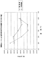
ろう付け後の強度の傾向を、図2−中間焼鈍のルートに示す。
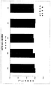
腐食電位の傾向を、図3−中間焼鈍のルートに示す。
熱伝導率の値は、およそ45%IACSである。
【0041】
さらに、移送ゲージの材料は、63μmまで直接に冷間圧延されて、200〜400℃の間の温度で部分的に焼鈍(後焼鈍)された。
【0042】
ろう付け後の強度の傾向を、図2−後焼鈍のルートに示す。
腐食電位の傾向を、図3−後焼鈍のルートに示す。
熱伝導率の値は、およそ45.5%IACSである。
【0043】
実施例3
実施例1に従って移送ゲージ(400μm)に製造した材料を入手して、
253μm、125μm、95μm、及び89μmのゲージに冷間圧延し、そして63μmのゲージに冷間圧延する前に、200〜400℃の間の範囲で2時間の中間焼鈍温度を付与した。最終圧延の圧下率は、それぞれ
70%以上、50%、34%、及び30%であった。
【0044】
ろう付け後の強度を、図4(135〜140MPaの間)に示す。
腐食電位を図5に示しており、中間焼鈍ゲージによりそれほど大きい影響を受けていない。
熱伝導率の値は、およそ45%IACSである。
【0045】
中間焼鈍ゲージは、ろう付けサイクル中の耐たわみ性に役立つろう付け後の粒子寸法を最大にするために変化している。例えば、中間焼鈍ゲージが厚くなるほど、ろう付け後の粒子寸法が小さくなる。さらに、中間焼鈍ゲージが減少すると、結晶粒のアスペクト比(厚さ方向に対する冷間加工方向の長さ)が増加する。
【0046】
実施例4
実施例1に記した組成に従って製造した材料を入手して、3.0mmのゲージまで熱間圧延する前に、460℃に加熱して約4時間保持した。そして、コイルを移送ゲージの400μmまで冷間圧延して、続いて、最終ゲージの63μmまで冷間圧延し360℃で中間焼鈍した。最終パスの圧下率は、45〜25%の範囲であった。
【0047】
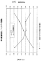
図6に、ろう付け後のUTSと結晶粒径との関係を示す。最大UTSを達成するためには、平均結晶粒径を50μm未満にする必要がある。しかしながら、ろう付け後の結晶粒径の減少は、材料の耐たわみ性を低下させる。
【0048】
ろう付け後の結晶粒径とUTSと耐たわみ性との釣り合いは、
予熱温度と加熱時間
中間焼鈍ゲージ
最終冷間圧延圧下率
の特定の組み合わせを選ぶことにより達成することができる。
【図面の簡単な説明】
【0049】
【図1】本発明の様々な工程を示す流れ図である。
【図2】ろう付け後の強度の傾向を示すグラフである。
【図3】腐食電位の傾向を示すグラフである(各組の左列は、中間焼鈍したもので、右列は、後焼鈍すなわち最終ゲージまで冷間圧延した後で焼鈍したものである)。
【図4】ろう付け後の機械的特性を示すグラフである。
【図5】腐食電位を示すグラフである。
【図6】ろう付け後のUTSと結晶粒径との間の関係を示すグラフである。[0001]
The present invention relates to an aluminum alloy, and more particularly to an aluminum alloy which is DC-cast and used as a fin material in a heat exchanger.
[0002]
In the automotive heat exchanger market, low cost fins, for example, have a balance of physical and chemical properties such as strength, formability, flex resistance, corrosion resistance, thermal conductivity and brazing properties. Material alloys are required.
[0003]
Aluminum alloy heat exchangers are widely used in the automotive industry and other fields with header plates, tank units, (aqueous) coolant tubes, and fins to facilitate heat exchange. Generally, the fins are joined to the tube by brazing. It has been a common practice to make the fins more electronegative than the tubes so that the fins function as sacrificial anodes, in order to reduce tube corrosion leading to coolant leakage. This has been achieved by adding Zn, Sn or In to the metal forming the fin.
[0004]
Nevertheless, the sacrificial effect must be balanced against the need to maintain heat transfer performance over the life of the heat exchanger. If the fan erodes too quickly, the heat transfer properties will be severely compromised. Furthermore, the use of a high strength fin material for a specific structure can provide an opportunity to reduce the size and weight of fins and / or tubing to achieve the purpose of weight reduction. Continuously cast materials have very high solidification rates (> 10 ° C./sec) and can be used to achieve the high levels of thermal conductivity required for miniaturization.
[0005]
WO-A-00 / 05426 discloses an aluminum alloy for fins having a high thermal conductivity. The invention disclosed therein relates to continuous strip casting of aluminum alloys, wherein the fin material has a thermal conductivity greater than 49.0% IACS after brazing. During continuous casting, thin strips are produced by quenching.
[0006]
Al-Fe-Si alloys are described in, for example, the following documents: British Patent GB1524355, British Patent GB1524354, WO-A-00 / 05426, Japanese Patent Application Laid-Open No. 2000-169926, Japanese Patent Application Laid-Open No. 8-218143, Japanese Patent Application Laid-Open No. 6-145861. And JP-A-4-154931 and JP-A-1-195257. The alloy compositions exemplified in those documents vary, but DC cast alloys are not disclosed.
[0007]
According to the first aspect of the present invention, the composition (% by weight) is Fe 0.8 to 1.5, Si 0.7 to 0.95, Mn 0.2 to 0.5, Zn 0.2 to 0.8, Provide DC casting alloys with Mg of 0.2 or less, Cu of 0.2 or less, Ti of less than 0.1, B of less than 0.01, C of less than 0.01, unavoidable impurities of 0.05 or less each, total amount of 0.15 or less, and the balance of Al It is to be.
[0008]
The alloys are used, for example, in applications for header plates or side supports, and have other uses, but are primarily directed to alloys for fin materials in heat exchangers.
[0009]
Cu is preferably present in the range of 0.05 to 0.2%, more preferably 0.1 to 0.15%. When present, Cu is included as a solid solution strengthening component.
[0010]
Mg is preferably present as a strengthening component. At high concentrations, undesired MgO deposits form on the metal surface during brazing. The Mg concentration is adjusted to a level where it does not matter. High concentrations of Mg form high melting point aluminum fluoride which is detrimental to the fluidity of the cladding in the presence of a flux mixture of K 3 AlF 6 and KAlF 4 . Preferably, Mg is present in the range of 0.05-0.2%, more preferably 0.1-0.15%.
[0011]
The strengthening effect of Cu and Mg must be balanced with the decrease in thermal conductivity due to these elements.
[0012]
The upper limit of the more preferable range of iron is 1.35%, but it is preferable that iron be present in the range of 0.8 to 1.4%. High concentrations cause the formation of excessively large intermetallic compound particles.
[0013]
Si lowers the alloy solidus below 610 ° C. above the upper limit of 0.95%, which is unacceptable as it is very close to the brazing temperature. The lower limit is determined by the amount of Si necessary to achieve the required post-brazing strength.
[0014]
Mn, if present at 0.5% or more, has an adverse effect on thermal conductivity. If Mn is 0.2% or less, a sufficient strengthening effect cannot be obtained.
[0015]
Zn is added to make the fin material more electronegative than the tubing of the heat exchanger, making it a sacrificial anode. If Zn exceeds 0.8%, the fin becomes too electronegative. Such a high Zn concentration adversely affects the thermal conductivity of the fin. If Zn is less than 0.2%, the fin cannot obtain sufficient electronegativity to become a sacrificial anode. Zn in the range of 0.5-0.7% is preferred.
[0016]
A second aspect of the present invention is to provide a DC-cast aluminum alloy fin material having a composition (% by weight) of Fe 0.8 to 1.5, Si 0.7 to 0.95, and Mn 0.2 0.5 to 0.5, Zn 0.2 to 0.8, Mg 0.2 or less, Cu 0.2 or less, Ti less than 0.1, B less than 0.01, C less than 0.01, unavoidable impurities each 0.05 or less, and the total amount is 0. The remaining amount of Al is 15 or less.
[0017]
The fin material sheet can be coated with a silicon-rich aluminum alloy. Preferred alloys are AA4343 and AA4045, although other silicon-rich alloys can be used. The silicon-enriched layer can optionally include additives such as Zn, Sn or In, which further render the fins electronegative.
[0018]
The fin material can have any of the preferred or optional forms described above. The fin material preferably has a thermal conductivity after brazing of at least 45% IACS.
[0019]
The aluminum alloy of the present invention is DC cast, and the reason will be described in detail later.
[0020]
The present invention also provides a brazed heat exchanger provided with the above-mentioned alloy fins.
[0021]
According to another aspect of the present invention, the composition (% by weight) is Fe 0.8 to 1.5, Si 0.7 to 0.95, Mn 0.2 to 0.5, Zn 0.2 to 0.8, MgO. A method for producing an alloy ingot of 0.2 or less, Cu 0.2 or less, Ti less than 0.1, B less than 0.01, C less than 0.01, inevitable impurities of 0.05 or less each and a total amount of 0.15 or less, and the balance of Al. The method includes DC casting of the alloy forming the ingot.
[0022]
In this aspect, the present invention aims to produce an ingot by conventional DC casting, thereby eliminating the need for continuous casting (eg, belt casting or twin roll casting). DC casting produces thick ingots that gradually cool during solidification. Continuous casting produces 3-20 mm thin strips that cool rapidly. Differences in cooling rates have a significant effect on the metallurgical structure of the cast product. These differences remain after processing the ingot into very thin gauge foil. By including DC casting, the method of the present invention can produce materials with properties comparable to continuous cast materials. Adjusting the particle size of the DC casting material is important to achieve these properties. For DC cast products, the cooling rate is approximately 1-5 ° C./sec, depending on the thickness of the ingot. Fin materials made from the alloy should have high thermal conductivity (typically appearing at about 595-605 ° C. in about 2-10 minutes) with good strength (UTS) and corrosion potential after brazing. is there. To facilitate measurement, thermal conductivity is usually indicated by measuring electrical conductivity. Since both are reduced by the elements in the solid solution, it is necessary to reduce the amount of soluble elements that form a solid solution during brazing. This is achieved by adjusting the particle size of the intermetallic compounds and dispersions in the rolled sheet and the chemical composition of the sheet.
[0023]
The high strength achieved by the DC cast material allows a thickness reduction of less than 100 μm, for example less than 75 μm, whereby new and improved lightweight fins can be achieved. Further, the alloy composition has been selected to maximize the absorption of the brazing sheet scrap, establish a low cost product route, and maximize reusability.
[0024]
Preferably, the method further comprises the steps of heating or soaking the DC cast ingot, hot rolling, cold rolling, and (intermediate) annealing, and, after the intermediate annealing, further cold rolling. A rolling step can be included. The final rolling reduction during cold rolling is preferably 25 to 45%.
[0025]
The soaking process may be a two-stage soaking process including heating to 580 to 620 ° C and holding for 8 hours or less, cooling to 460 to 500 ° C and holding for 8 hours or less. .
[0026]
Alternatively, the heating step can be a simple hot rolling step that involves heating to 460-540 ° C. and holding for 8 hours or less. This simple hot rolling process is not sufficient to achieve complete soaking of the ingot. The purpose is to bring the ingot to a uniform temperature in order to promote hot rolling.
[0027]
The hot rolling is performed to 2.5 to 5.0 mm, and the outlet temperature from the hot rolling mill is usually preferably 280 to 360 ° C. If there is an intermediate annealing step, it is preferable to subsequently cold-roll to 50 to 700 μm. In cold rolling to the final gauge without performing intermediate annealing, finish annealing is performed thereafter.
[0028]
The (intermediate) annealing step can be a one-step step of holding at 250 to 450 ° C., preferably at that temperature for 2 to 4 hours. Alternatively, a two-step process including heating to 300 to 500 ° C. (preferably maintained for 4 hours or less) and then cooling to 200 to 350 ° C. (preferably maintained for 4 hours or less) may be employed. Good.
[0029]
Alternatively, the annealing can be performed in a continuous annealing furnace, where the strip is supplied as a single strand, significantly increasing the heating rate and reducing the required holding time. Thus, high annealing temperatures and short annealing times are achieved.
[0030]
The method may further include a brazing step, wherein the reduction of the IACS during brazing is less than 5% units so that the intermetallic compounds and / or dispersions present in the rolled product are reduced. Increase the particle size sufficiently.
[0031]
During the brazing cycle, small (submicron) dispersions dissolve easily and solute concentrations increase. Rapid cooling after brazing retains substantially all of the solute in the solid solution, thereby reducing IACS values and thermal conductivity. As the average size of the dispersion increases, the amount of dissolution during the brazing cycle decreases, thereby mitigating the decrease in IACS and thermal conductivity. The size of the dispersion is increased through the use of a special soaking and / or annealing treatment that coarsens the α-Al (Fe, Mn) Si dispersion and possibly also some of the intermetallic particles. . The soaking treatment is a continuous treatment at two temperatures, preferably comprising a first high temperature treatment followed by a low temperature treatment. Annealing can follow a similar pattern.
[0032]
In the absence of these special soaking and annealing treatments, the dispersion present in the sheet generally has an average of substantially 1 micron or less (as determined by the mean linear intercept method). Has dimensions. Through special soaking and annealing treatments, the average dispersion size is increased, for example, to more than 0.5 microns, preferably to more than 1 μm, ideally to more than 2 μm, but to less than 10 μm. To Thermodynamic calculations reveal that these particles are unlikely to undergo a phase transition during the brazing cycle.
[0033]
The intermetallic particles (containing Fe, Mn and Si along with other elements) are substantially larger than the dispersion. These grain sizes are determined during solidification and may fracture during rolling.
[0034]
According to a further aspect of the present invention, the composition (% by weight) is Fe 0.8-1.5, Si 0.7-0.95, Mn 0.2-0.5, Zn 0.2-0.8, MgO. 2 or less, Cu 0.2 or less, Ti less than 0.1, B less than 0.01, C less than 0.01, unavoidable impurities are each 0.05 or less, and the total amount is 0.15 or less. Provided is a method of making, including DC casting of an alloy, heating or soaking, hot rolling, cold rolling, and annealing or intermediate annealing.
[0035]
The present invention will now be described by way of example with reference to the following drawings and examples.
Referring to FIG. 1, various processes of a DC ingot within the scope of the present invention, including preferred conditions for each step, are shown.
[0036]
Example 1
An ingot approximately 1350 mm x 600 mm and weighing more than 7,500 kg was DC cast with the following composition.
[Table 1]
[0037]
One ingot (route 1 in FIG. 1) was heated to 520 ° C. and held for about 4 hours before hot rolling to 3.0 mm at an exit temperature of about 325 ° C. The coil is then cold rolled to a 400 μm transfer gauge, then cold rolled to a 95 μm gauge, subjected to an intermediate anneal at 270 ° C. for 2 hours, and further to a final gauge of 63 μm (final draft). Was about 34%).
[0038]
After brazing, the UST is 138 MPa,% IACS is 46% IACS, and the potential is -755 mV (according to ASTM G69 standard test method for measuring corrosion potential of aluminum alloy).
[0039]
Example 2
A material manufactured according to Example 1 to the range of the transfer gauge (400 μm) was obtained and given an intermediate annealing temperature of between 200 and 400 ° C. for 2 hours before cold rolling to a 63 μm gauge.
[0040]
The tendency of the strength after brazing is shown in FIG.
The tendency of the corrosion potential is shown in FIG.
The value of the thermal conductivity is approximately 45% IACS.
[0041]
Further, the material of the transfer gauge was cold rolled directly to 63 μm and partially annealed (post-annealed) at a temperature between 200 and 400 ° C.
[0042]
The tendency of the strength after brazing is shown in FIG. 2-Post-annealing route.
The tendency of the corrosion potential is shown in the route of post-annealing in FIG.
The value of the thermal conductivity is approximately 45.5% IACS.
[0043]
Example 3
Obtain the material manufactured in the transfer gauge (400 μm) according to Example 1,
Before being cold rolled to 253, 125, 95 and 89 μm gauges, and before cold rolling to 63 μm gauges, an intermediate annealing temperature in the range between 200 and 400 ° C. was applied for 2 hours. The rolling reduction of the final rolling was 70% or more, 50%, 34%, and 30%, respectively.
[0044]
The strength after brazing is shown in FIG. 4 (between 135 and 140 MPa).
The corrosion potential is shown in FIG. 5 and is not significantly affected by the intermediate annealing gauge.
The value of the thermal conductivity is approximately 45% IACS.
[0045]
Intermediate annealing gauges have been varied to maximize the post-brazing particle size which helps with deflection resistance during the brazing cycle. For example, the thicker the intermediate annealing gauge, the smaller the particle size after brazing. Furthermore, as the intermediate annealing gauge decreases, the aspect ratio of the crystal grains (the length in the cold working direction with respect to the thickness direction) increases.
[0046]
Example 4
A material made according to the composition described in Example 1 was obtained and heated to 460 ° C. and held for about 4 hours before hot rolling to a 3.0 mm gauge. The coil was cold-rolled to a transfer gauge of 400 μm, subsequently cold-rolled to a final gauge of 63 μm, and annealed at 360 ° C. The reduction of the final pass ranged from 45 to 25%.
[0047]
FIG. 6 shows the relationship between the UTS after brazing and the crystal grain size. In order to achieve the maximum UTS, the average crystal grain size needs to be less than 50 μm. However, the reduction in grain size after brazing reduces the deflection resistance of the material.
[0048]
The balance between the crystal grain size after brazing, UTS and deflection resistance is
This can be achieved by choosing a specific combination of preheating temperature and heating time intermediate annealing gauge final cold rolling reduction.
[Brief description of the drawings]
[0049]
FIG. 1 is a flowchart illustrating various steps of the present invention.
FIG. 2 is a graph showing a tendency of strength after brazing.
FIG. 3 is a graph showing the trend of the corrosion potential (the left column of each set is intermediately annealed, and the right column is post-annealing, ie, cold rolling to the final gauge, followed by annealing).
FIG. 4 is a graph showing mechanical properties after brazing.
FIG. 5 is a graph showing corrosion potential.
FIG. 6 is a graph showing the relationship between UTS after brazing and crystal grain size.