JP2004509793A - Method for regenerating and / or processing elastomer mixed with multi-screw extruder and filler - Google Patents

Method for regenerating and / or processing elastomer mixed with multi-screw extruder and filler Download PDF

Info

Publication number
JP2004509793A
JP2004509793A JP2002534060A JP2002534060A JP2004509793A JP 2004509793 A JP2004509793 A JP 2004509793A JP 2002534060 A JP2002534060 A JP 2002534060A JP 2002534060 A JP2002534060 A JP 2002534060A JP 2004509793 A JP2004509793 A JP 2004509793A
Authority
JP
Japan
Prior art keywords
extruder
kneading
zone
elastomer
product
Prior art date
Legal status (The legal status is an assumption and is not a legal conclusion. Google has not performed a legal analysis and makes no representation as to the accuracy of the status listed.)
Pending
Application number
JP2002534060A
Other languages
Japanese (ja)
Inventor
シュトルム・アヒム−フィリップ
インネレブナー・フェデリコ
Original Assignee
ビユーラー・アクチエンゲゼルシヤフト
Priority date (The priority date is an assumption and is not a legal conclusion. Google has not performed a legal analysis and makes no representation as to the accuracy of the date listed.)
Filing date
Publication date
Application filed by ビユーラー・アクチエンゲゼルシヤフト filed Critical ビユーラー・アクチエンゲゼルシヤフト
Publication of JP2004509793A publication Critical patent/JP2004509793A/en
Pending legal-status Critical Current

Links

Images

Classifications

    • BPERFORMING OPERATIONS; TRANSPORTING
    • B29WORKING OF PLASTICS; WORKING OF SUBSTANCES IN A PLASTIC STATE IN GENERAL
    • B29CSHAPING OR JOINING OF PLASTICS; SHAPING OF MATERIAL IN A PLASTIC STATE, NOT OTHERWISE PROVIDED FOR; AFTER-TREATMENT OF THE SHAPED PRODUCTS, e.g. REPAIRING
    • B29C48/00Extrusion moulding, i.e. expressing the moulding material through a die or nozzle which imparts the desired form; Apparatus therefor
    • B29C48/25Component parts, details or accessories; Auxiliary operations
    • B29C48/78Thermal treatment of the extrusion moulding material or of preformed parts or layers, e.g. by heating or cooling
    • B29C48/80Thermal treatment of the extrusion moulding material or of preformed parts or layers, e.g. by heating or cooling at the plasticising zone, e.g. by heating cylinders
    • B29C48/84Thermal treatment of the extrusion moulding material or of preformed parts or layers, e.g. by heating or cooling at the plasticising zone, e.g. by heating cylinders by heating or cooling the feeding screws
    • BPERFORMING OPERATIONS; TRANSPORTING
    • B29WORKING OF PLASTICS; WORKING OF SUBSTANCES IN A PLASTIC STATE IN GENERAL
    • B29BPREPARATION OR PRETREATMENT OF THE MATERIAL TO BE SHAPED; MAKING GRANULES OR PREFORMS; RECOVERY OF PLASTICS OR OTHER CONSTITUENTS OF WASTE MATERIAL CONTAINING PLASTICS
    • B29B7/00Mixing; Kneading
    • B29B7/30Mixing; Kneading continuous, with mechanical mixing or kneading devices
    • B29B7/34Mixing; Kneading continuous, with mechanical mixing or kneading devices with movable mixing or kneading devices
    • B29B7/38Mixing; Kneading continuous, with mechanical mixing or kneading devices with movable mixing or kneading devices rotary
    • B29B7/46Mixing; Kneading continuous, with mechanical mixing or kneading devices with movable mixing or kneading devices rotary with more than one shaft
    • B29B7/48Mixing; Kneading continuous, with mechanical mixing or kneading devices with movable mixing or kneading devices rotary with more than one shaft with intermeshing devices, e.g. screws
    • B29B7/485Mixing; Kneading continuous, with mechanical mixing or kneading devices with movable mixing or kneading devices rotary with more than one shaft with intermeshing devices, e.g. screws with three or more shafts provided with screws
    • BPERFORMING OPERATIONS; TRANSPORTING
    • B29WORKING OF PLASTICS; WORKING OF SUBSTANCES IN A PLASTIC STATE IN GENERAL
    • B29BPREPARATION OR PRETREATMENT OF THE MATERIAL TO BE SHAPED; MAKING GRANULES OR PREFORMS; RECOVERY OF PLASTICS OR OTHER CONSTITUENTS OF WASTE MATERIAL CONTAINING PLASTICS
    • B29B7/00Mixing; Kneading
    • B29B7/30Mixing; Kneading continuous, with mechanical mixing or kneading devices
    • B29B7/58Component parts, details or accessories; Auxiliary operations
    • B29B7/60Component parts, details or accessories; Auxiliary operations for feeding, e.g. end guides for the incoming material
    • B29B7/603Component parts, details or accessories; Auxiliary operations for feeding, e.g. end guides for the incoming material in measured doses, e.g. proportioning of several materials
    • BPERFORMING OPERATIONS; TRANSPORTING
    • B29WORKING OF PLASTICS; WORKING OF SUBSTANCES IN A PLASTIC STATE IN GENERAL
    • B29BPREPARATION OR PRETREATMENT OF THE MATERIAL TO BE SHAPED; MAKING GRANULES OR PREFORMS; RECOVERY OF PLASTICS OR OTHER CONSTITUENTS OF WASTE MATERIAL CONTAINING PLASTICS
    • B29B7/00Mixing; Kneading
    • B29B7/74Mixing; Kneading using other mixers or combinations of mixers, e.g. of dissimilar mixers ; Plant
    • B29B7/7476Systems, i.e. flow charts or diagrams; Plants
    • B29B7/7495Systems, i.e. flow charts or diagrams; Plants for mixing rubber
    • BPERFORMING OPERATIONS; TRANSPORTING
    • B29WORKING OF PLASTICS; WORKING OF SUBSTANCES IN A PLASTIC STATE IN GENERAL
    • B29BPREPARATION OR PRETREATMENT OF THE MATERIAL TO BE SHAPED; MAKING GRANULES OR PREFORMS; RECOVERY OF PLASTICS OR OTHER CONSTITUENTS OF WASTE MATERIAL CONTAINING PLASTICS
    • B29B7/00Mixing; Kneading
    • B29B7/80Component parts, details or accessories; Auxiliary operations
    • B29B7/88Adding charges, i.e. additives
    • B29B7/90Fillers or reinforcements, e.g. fibres
    • BPERFORMING OPERATIONS; TRANSPORTING
    • B29WORKING OF PLASTICS; WORKING OF SUBSTANCES IN A PLASTIC STATE IN GENERAL
    • B29BPREPARATION OR PRETREATMENT OF THE MATERIAL TO BE SHAPED; MAKING GRANULES OR PREFORMS; RECOVERY OF PLASTICS OR OTHER CONSTITUENTS OF WASTE MATERIAL CONTAINING PLASTICS
    • B29B7/00Mixing; Kneading
    • B29B7/80Component parts, details or accessories; Auxiliary operations
    • B29B7/88Adding charges, i.e. additives
    • B29B7/94Liquid charges
    • BPERFORMING OPERATIONS; TRANSPORTING
    • B29WORKING OF PLASTICS; WORKING OF SUBSTANCES IN A PLASTIC STATE IN GENERAL
    • B29CSHAPING OR JOINING OF PLASTICS; SHAPING OF MATERIAL IN A PLASTIC STATE, NOT OTHERWISE PROVIDED FOR; AFTER-TREATMENT OF THE SHAPED PRODUCTS, e.g. REPAIRING
    • B29C48/00Extrusion moulding, i.e. expressing the moulding material through a die or nozzle which imparts the desired form; Apparatus therefor
    • B29C48/25Component parts, details or accessories; Auxiliary operations
    • B29C48/285Feeding the extrusion material to the extruder
    • B29C48/29Feeding the extrusion material to the extruder in liquid form
    • BPERFORMING OPERATIONS; TRANSPORTING
    • B29WORKING OF PLASTICS; WORKING OF SUBSTANCES IN A PLASTIC STATE IN GENERAL
    • B29CSHAPING OR JOINING OF PLASTICS; SHAPING OF MATERIAL IN A PLASTIC STATE, NOT OTHERWISE PROVIDED FOR; AFTER-TREATMENT OF THE SHAPED PRODUCTS, e.g. REPAIRING
    • B29C48/00Extrusion moulding, i.e. expressing the moulding material through a die or nozzle which imparts the desired form; Apparatus therefor
    • B29C48/25Component parts, details or accessories; Auxiliary operations
    • B29C48/285Feeding the extrusion material to the extruder
    • B29C48/297Feeding the extrusion material to the extruder at several locations, e.g. using several hoppers or using a separate additive feeding
    • BPERFORMING OPERATIONS; TRANSPORTING
    • B29WORKING OF PLASTICS; WORKING OF SUBSTANCES IN A PLASTIC STATE IN GENERAL
    • B29CSHAPING OR JOINING OF PLASTICS; SHAPING OF MATERIAL IN A PLASTIC STATE, NOT OTHERWISE PROVIDED FOR; AFTER-TREATMENT OF THE SHAPED PRODUCTS, e.g. REPAIRING
    • B29C48/00Extrusion moulding, i.e. expressing the moulding material through a die or nozzle which imparts the desired form; Apparatus therefor
    • B29C48/25Component parts, details or accessories; Auxiliary operations
    • B29C48/36Means for plasticising or homogenising the moulding material or forcing it through the nozzle or die
    • B29C48/395Means for plasticising or homogenising the moulding material or forcing it through the nozzle or die using screws surrounded by a cooperating barrel, e.g. single screw extruders
    • B29C48/40Means for plasticising or homogenising the moulding material or forcing it through the nozzle or die using screws surrounded by a cooperating barrel, e.g. single screw extruders using two or more parallel screws or at least two parallel non-intermeshing screws, e.g. twin screw extruders
    • B29C48/402Means for plasticising or homogenising the moulding material or forcing it through the nozzle or die using screws surrounded by a cooperating barrel, e.g. single screw extruders using two or more parallel screws or at least two parallel non-intermeshing screws, e.g. twin screw extruders the screws having intermeshing parts
    • BPERFORMING OPERATIONS; TRANSPORTING
    • B29WORKING OF PLASTICS; WORKING OF SUBSTANCES IN A PLASTIC STATE IN GENERAL
    • B29CSHAPING OR JOINING OF PLASTICS; SHAPING OF MATERIAL IN A PLASTIC STATE, NOT OTHERWISE PROVIDED FOR; AFTER-TREATMENT OF THE SHAPED PRODUCTS, e.g. REPAIRING
    • B29C48/00Extrusion moulding, i.e. expressing the moulding material through a die or nozzle which imparts the desired form; Apparatus therefor
    • B29C48/25Component parts, details or accessories; Auxiliary operations
    • B29C48/36Means for plasticising or homogenising the moulding material or forcing it through the nozzle or die
    • B29C48/395Means for plasticising or homogenising the moulding material or forcing it through the nozzle or die using screws surrounded by a cooperating barrel, e.g. single screw extruders
    • B29C48/40Means for plasticising or homogenising the moulding material or forcing it through the nozzle or die using screws surrounded by a cooperating barrel, e.g. single screw extruders using two or more parallel screws or at least two parallel non-intermeshing screws, e.g. twin screw extruders
    • B29C48/425Means for plasticising or homogenising the moulding material or forcing it through the nozzle or die using screws surrounded by a cooperating barrel, e.g. single screw extruders using two or more parallel screws or at least two parallel non-intermeshing screws, e.g. twin screw extruders using three or more screws
    • B29C48/43Ring extruders
    • BPERFORMING OPERATIONS; TRANSPORTING
    • B29WORKING OF PLASTICS; WORKING OF SUBSTANCES IN A PLASTIC STATE IN GENERAL
    • B29CSHAPING OR JOINING OF PLASTICS; SHAPING OF MATERIAL IN A PLASTIC STATE, NOT OTHERWISE PROVIDED FOR; AFTER-TREATMENT OF THE SHAPED PRODUCTS, e.g. REPAIRING
    • B29C48/00Extrusion moulding, i.e. expressing the moulding material through a die or nozzle which imparts the desired form; Apparatus therefor
    • B29C48/25Component parts, details or accessories; Auxiliary operations
    • B29C48/36Means for plasticising or homogenising the moulding material or forcing it through the nozzle or die
    • B29C48/395Means for plasticising or homogenising the moulding material or forcing it through the nozzle or die using screws surrounded by a cooperating barrel, e.g. single screw extruders
    • B29C48/40Means for plasticising or homogenising the moulding material or forcing it through the nozzle or die using screws surrounded by a cooperating barrel, e.g. single screw extruders using two or more parallel screws or at least two parallel non-intermeshing screws, e.g. twin screw extruders
    • B29C48/435Sub-screws
    • BPERFORMING OPERATIONS; TRANSPORTING
    • B29WORKING OF PLASTICS; WORKING OF SUBSTANCES IN A PLASTIC STATE IN GENERAL
    • B29CSHAPING OR JOINING OF PLASTICS; SHAPING OF MATERIAL IN A PLASTIC STATE, NOT OTHERWISE PROVIDED FOR; AFTER-TREATMENT OF THE SHAPED PRODUCTS, e.g. REPAIRING
    • B29C48/00Extrusion moulding, i.e. expressing the moulding material through a die or nozzle which imparts the desired form; Apparatus therefor
    • B29C48/25Component parts, details or accessories; Auxiliary operations
    • B29C48/36Means for plasticising or homogenising the moulding material or forcing it through the nozzle or die
    • B29C48/50Details of extruders
    • B29C48/505Screws
    • B29C48/52Screws with an outer diameter varying along the longitudinal axis, e.g. for obtaining different thread clearance
    • BPERFORMING OPERATIONS; TRANSPORTING
    • B29WORKING OF PLASTICS; WORKING OF SUBSTANCES IN A PLASTIC STATE IN GENERAL
    • B29CSHAPING OR JOINING OF PLASTICS; SHAPING OF MATERIAL IN A PLASTIC STATE, NOT OTHERWISE PROVIDED FOR; AFTER-TREATMENT OF THE SHAPED PRODUCTS, e.g. REPAIRING
    • B29C48/00Extrusion moulding, i.e. expressing the moulding material through a die or nozzle which imparts the desired form; Apparatus therefor
    • B29C48/25Component parts, details or accessories; Auxiliary operations
    • B29C48/36Means for plasticising or homogenising the moulding material or forcing it through the nozzle or die
    • B29C48/50Details of extruders
    • B29C48/76Venting, drying means; Degassing means
    • BPERFORMING OPERATIONS; TRANSPORTING
    • B29WORKING OF PLASTICS; WORKING OF SUBSTANCES IN A PLASTIC STATE IN GENERAL
    • B29CSHAPING OR JOINING OF PLASTICS; SHAPING OF MATERIAL IN A PLASTIC STATE, NOT OTHERWISE PROVIDED FOR; AFTER-TREATMENT OF THE SHAPED PRODUCTS, e.g. REPAIRING
    • B29C48/00Extrusion moulding, i.e. expressing the moulding material through a die or nozzle which imparts the desired form; Apparatus therefor
    • B29C48/25Component parts, details or accessories; Auxiliary operations
    • B29C48/78Thermal treatment of the extrusion moulding material or of preformed parts or layers, e.g. by heating or cooling
    • B29C48/80Thermal treatment of the extrusion moulding material or of preformed parts or layers, e.g. by heating or cooling at the plasticising zone, e.g. by heating cylinders
    • B29C48/83Heating or cooling the cylinders
    • B29C48/834Cooling
    • BPERFORMING OPERATIONS; TRANSPORTING
    • B29WORKING OF PLASTICS; WORKING OF SUBSTANCES IN A PLASTIC STATE IN GENERAL
    • B29CSHAPING OR JOINING OF PLASTICS; SHAPING OF MATERIAL IN A PLASTIC STATE, NOT OTHERWISE PROVIDED FOR; AFTER-TREATMENT OF THE SHAPED PRODUCTS, e.g. REPAIRING
    • B29C48/00Extrusion moulding, i.e. expressing the moulding material through a die or nozzle which imparts the desired form; Apparatus therefor
    • B29C48/25Component parts, details or accessories; Auxiliary operations
    • B29C48/78Thermal treatment of the extrusion moulding material or of preformed parts or layers, e.g. by heating or cooling
    • B29C48/80Thermal treatment of the extrusion moulding material or of preformed parts or layers, e.g. by heating or cooling at the plasticising zone, e.g. by heating cylinders
    • B29C48/84Thermal treatment of the extrusion moulding material or of preformed parts or layers, e.g. by heating or cooling at the plasticising zone, e.g. by heating cylinders by heating or cooling the feeding screws
    • B29C48/85Cooling
    • BPERFORMING OPERATIONS; TRANSPORTING
    • B29WORKING OF PLASTICS; WORKING OF SUBSTANCES IN A PLASTIC STATE IN GENERAL
    • B29BPREPARATION OR PRETREATMENT OF THE MATERIAL TO BE SHAPED; MAKING GRANULES OR PREFORMS; RECOVERY OF PLASTICS OR OTHER CONSTITUENTS OF WASTE MATERIAL CONTAINING PLASTICS
    • B29B7/00Mixing; Kneading
    • B29B7/30Mixing; Kneading continuous, with mechanical mixing or kneading devices
    • B29B7/58Component parts, details or accessories; Auxiliary operations
    • B29B7/72Measuring, controlling or regulating
    • B29B7/728Measuring data of the driving system, e.g. torque, speed, power, vibration
    • BPERFORMING OPERATIONS; TRANSPORTING
    • B29WORKING OF PLASTICS; WORKING OF SUBSTANCES IN A PLASTIC STATE IN GENERAL
    • B29BPREPARATION OR PRETREATMENT OF THE MATERIAL TO BE SHAPED; MAKING GRANULES OR PREFORMS; RECOVERY OF PLASTICS OR OTHER CONSTITUENTS OF WASTE MATERIAL CONTAINING PLASTICS
    • B29B7/00Mixing; Kneading
    • B29B7/80Component parts, details or accessories; Auxiliary operations
    • B29B7/84Venting or degassing ; Removing liquids, e.g. by evaporating components
    • B29B7/845Venting, degassing or removing evaporated components in devices with rotary stirrers
    • BPERFORMING OPERATIONS; TRANSPORTING
    • B29WORKING OF PLASTICS; WORKING OF SUBSTANCES IN A PLASTIC STATE IN GENERAL
    • B29CSHAPING OR JOINING OF PLASTICS; SHAPING OF MATERIAL IN A PLASTIC STATE, NOT OTHERWISE PROVIDED FOR; AFTER-TREATMENT OF THE SHAPED PRODUCTS, e.g. REPAIRING
    • B29C48/00Extrusion moulding, i.e. expressing the moulding material through a die or nozzle which imparts the desired form; Apparatus therefor
    • B29C48/03Extrusion moulding, i.e. expressing the moulding material through a die or nozzle which imparts the desired form; Apparatus therefor characterised by the shape of the extruded material at extrusion
    • BPERFORMING OPERATIONS; TRANSPORTING
    • B29WORKING OF PLASTICS; WORKING OF SUBSTANCES IN A PLASTIC STATE IN GENERAL
    • B29CSHAPING OR JOINING OF PLASTICS; SHAPING OF MATERIAL IN A PLASTIC STATE, NOT OTHERWISE PROVIDED FOR; AFTER-TREATMENT OF THE SHAPED PRODUCTS, e.g. REPAIRING
    • B29C48/00Extrusion moulding, i.e. expressing the moulding material through a die or nozzle which imparts the desired form; Apparatus therefor
    • B29C48/25Component parts, details or accessories; Auxiliary operations
    • B29C48/285Feeding the extrusion material to the extruder
    • B29C48/288Feeding the extrusion material to the extruder in solid form, e.g. powder or granules
    • B29C48/2886Feeding the extrusion material to the extruder in solid form, e.g. powder or granules of fibrous, filamentary or filling materials, e.g. thin fibrous reinforcements or fillers
    • BPERFORMING OPERATIONS; TRANSPORTING
    • B29WORKING OF PLASTICS; WORKING OF SUBSTANCES IN A PLASTIC STATE IN GENERAL
    • B29CSHAPING OR JOINING OF PLASTICS; SHAPING OF MATERIAL IN A PLASTIC STATE, NOT OTHERWISE PROVIDED FOR; AFTER-TREATMENT OF THE SHAPED PRODUCTS, e.g. REPAIRING
    • B29C48/00Extrusion moulding, i.e. expressing the moulding material through a die or nozzle which imparts the desired form; Apparatus therefor
    • B29C48/25Component parts, details or accessories; Auxiliary operations
    • B29C48/36Means for plasticising or homogenising the moulding material or forcing it through the nozzle or die
    • B29C48/50Details of extruders
    • B29C48/76Venting, drying means; Degassing means
    • B29C48/762Vapour stripping
    • BPERFORMING OPERATIONS; TRANSPORTING
    • B29WORKING OF PLASTICS; WORKING OF SUBSTANCES IN A PLASTIC STATE IN GENERAL
    • B29KINDEXING SCHEME ASSOCIATED WITH SUBCLASSES B29B, B29C OR B29D, RELATING TO MOULDING MATERIALS OR TO MATERIALS FOR MOULDS, REINFORCEMENTS, FILLERS OR PREFORMED PARTS, e.g. INSERTS
    • B29K2007/00Use of natural rubber as moulding material
    • BPERFORMING OPERATIONS; TRANSPORTING
    • B29WORKING OF PLASTICS; WORKING OF SUBSTANCES IN A PLASTIC STATE IN GENERAL
    • B29KINDEXING SCHEME ASSOCIATED WITH SUBCLASSES B29B, B29C OR B29D, RELATING TO MOULDING MATERIALS OR TO MATERIALS FOR MOULDS, REINFORCEMENTS, FILLERS OR PREFORMED PARTS, e.g. INSERTS
    • B29K2009/00Use of rubber derived from conjugated dienes, as moulding material
    • BPERFORMING OPERATIONS; TRANSPORTING
    • B29WORKING OF PLASTICS; WORKING OF SUBSTANCES IN A PLASTIC STATE IN GENERAL
    • B29KINDEXING SCHEME ASSOCIATED WITH SUBCLASSES B29B, B29C OR B29D, RELATING TO MOULDING MATERIALS OR TO MATERIALS FOR MOULDS, REINFORCEMENTS, FILLERS OR PREFORMED PARTS, e.g. INSERTS
    • B29K2105/00Condition, form or state of moulded material or of the material to be shaped
    • B29K2105/0005Condition, form or state of moulded material or of the material to be shaped containing compounding ingredients
    • BPERFORMING OPERATIONS; TRANSPORTING
    • B29WORKING OF PLASTICS; WORKING OF SUBSTANCES IN A PLASTIC STATE IN GENERAL
    • B29KINDEXING SCHEME ASSOCIATED WITH SUBCLASSES B29B, B29C OR B29D, RELATING TO MOULDING MATERIALS OR TO MATERIALS FOR MOULDS, REINFORCEMENTS, FILLERS OR PREFORMED PARTS, e.g. INSERTS
    • B29K2105/00Condition, form or state of moulded material or of the material to be shaped
    • B29K2105/06Condition, form or state of moulded material or of the material to be shaped containing reinforcements, fillers or inserts
    • B29K2105/16Fillers

Abstract

A multi-shaft extruder is disclosed with at least two shafts for compounding and/or molding an elastomer staggered with filler, in particular rubber, with at least one softener and/or additives. The extruder comprises the following in succession in the direction of product transport: a feed zone, into which the elastomer and softener and/or additives are metered; a mastication/plasticization zone with at least one kneading element, into which the elastomer with the softener and/or additives is transferred to a flowable, cohesive mixture; a dispersing zone with at least one additional kneading element, in which the filler in the elastomer is comminuted and distributed; and the kneading elements having a comb and the extruder having a casing inner wall and wherein a gap with a gap width Z of about {fraction (1/100 to about {fraction (1/10 of the kneading element diameter D is present between the comb of the kneading elements and the casing inner wall of the extruder, wherein the diameter is defined as the maximal diameter of a kneading element from comb to comb.

Description

【0001】
【発明の属する技術分野】この発明は、請求項1に基づく多軸押出機と充填材と混合されたエラストマ−、例えば煤を備えるゴムを再生及び/又は加工する請求項21に基づく方法に関する。
【0002】
【従来の技術】
ゴム混合物を再生するために多段で非連続的方法工程が知られている。ゴムの再生はおよそ2〜3分の混合周期に中身250〜500lを備えるバッチ混合物でほぼ2通過で行われる。引き続く形削りは(タイヤ用)ロ−ラ機構或いは(側面など用)押出機により行われる。混合ホ−ルの構造と装置の高い原価並びにその運転の高い費用は生産原価を低下させることを困難にする。
【0003】
数年来、ゴム工業では加工処理を簡略化しようとしている。ゴムの連続的再生は、それが例えば熱可塑性合成樹脂において公知であるように、数年来、出来る限りの解決試みと見做される。人間は連続的方法で次の主利点を期待する;
僅かな振動(特に品質)と製品損失、広範囲な自動化方法、僅かなエネルギ−消費、僅かな大気汚染。
【0004】
ゴムの連続的再生は、数年来のゴム工業の願望である。ゴム再生に適した連続的混合方法は総ての混合組成の連続的調合性並びにこの構成要素の正確な調合を前提としている。ゴムが(天然や合成)通常には包装物で納入される従来の通常の配達形態は経済的な連続的再生を難しくしていた。粉末ゴムは既に長く知られているが、しかし高過ぎた。粉末ゴムの経済的製造を許容する新たな開発は、連続的ゴム再生における新たな可能性を切り開く。
【0005】
充填材で混合された粉末ゴムは最近、連続的乾燥と濾過によってゴム乳濁液と充填材懸濁液の間の共通沈澱により得られる。この方法で得られた粉末ゴムは自由流れで注入できる。
【0006】
ゴムを混合する現在の公知方法は一般に正接する或いは互いに係合するこね軸を備える内部混合機、衝撃混合機を備える裁断圧延機及び/又はバッチオフ装置において冷却が行われる前に混合された充填物を均質化して得られた混合物を圧延シ−ト或いは供給ストリップに切断するバッチオフ圧延機を使用する。
【0007】
択一的に人間は溶融押出機やロ−ラダイ装置を使用する。
【0008】
加熱の強過ぎ或いは混合の開始の危険を生じることなしに、混合の良好な分散を保証するために、個々の充填材の混合の際にしばしば二段混合処理が必要であり、特に高い硬度或いはム−ネイ粘性の高い値による混合の際に二段混合処理が必要である。低い硬度をもつ物品の混合は良好なポリマ−分散を保証するために延長された混合時間と多数通過の混合とを必要とする。
【0009】
今日の混合処置は資本集中であって高いエネルギ−価格と運転価格を生ぜしめる。さらに、いつも、不安定な製品品質の危機が生じ、それは大きなゴム包装物が包装物密度で相違していることによって生じるばかりではなく、混合製造のこれらの作業態様が個々の充填ではその本質により可変であり、さらに多数の処理工程を包含する。
【0010】
内部混合機(或いは捏ね機)は今日なお、ゴム混合物の製造における中央集合体である。内部混合機内では二つの機械ブレ−ドが回転し、その幾何学は同時に混合物の軸方向と半径方向移動或いは混ぜ合わせが生じるように整合されている。従来、こねブレ−ドは異なる回転数で、反対方向に且つ最近の内部混合機噛み合いで回転する。
【0011】
内部混合機は1リットルから(実験機械)450リットルまで(タイヤ捏ね機)の値において利用できる。後者は複数の階層にわたり、複数ミリオンフランケン(スイスフラン)を必要とする。
【0012】
注入開口はブレ−ド隙間に位置する。それら開口は混合中に液圧作動されたスタンプにより封鎖される。2バ−ルから10バ−ルまでのスタンピング圧力により混合品が本来の混合室で圧縮され、放出を防止される。混合時間は典型的には2分である。
【0013】
混合室は壁に冷却する穴を包含する。捏ねブレ−ドは同様に冷却するように穿孔されている。
【0014】
混合室の床における放出開口は所謂滑動式或いは枢着式サドルによって液圧的に密封される。開口は枢着式サドルでは十分な大きさにまで迅速に開放され、それにより迅速な放出を可能とする。
【0015】
内部混合機の駆動はkg当たり10kWまでのより高い効率の電動モ−タによって行われる。最近の内部混合機はブレ−ド回転数において無段階に調整できる。
【0016】
内部混合機の装入は半自動的に所謂予定切換え装置によって行われる。注入可能な充填材は煤のように充填材装置(容器、サイロ或いは柔軟な大きいバック)から自動的に放出され、計量されて内部混合機へ供給される。しばしば変更する少量とボ−ル状ゴムはボ−ルカッタ−内の粉砕後に手動で計量される。手動計量の際に前もって計量された構成要素は捏ね機軸に供給される。
【0017】
ゴム後に充填材と添加材が共通に供給されて、最後に流体成分(可塑剤)が噴射される。
【0018】
ゴムは混合処理の低回転数における第一位相において加熱されて可塑性化される。その後に高回転数において混合作業は(分布的に且つ分散的に)開始される。混合作業における限定された要因は温度である。混合処理を監視して制御するために捏ね機駆動手段の質量温度と出力消費が測定される。両方が一緒に、均質な混合特性を得るために周期から周期まで再生されなければならない特徴的画像を与える。仕上がり混合物は内部混合機から床上混合機を備える混合圧延機或いは冷却圧延機に落下し、そこで連続的シ−トとして引き出され、バッチオフ装置で冷却され、剥離剤を備え、乾燥され、最後にストリップに裁断されて、パレット上に置かれる。
【0019】
ゴムのようなエラストマ−の加工における重要な部分工程はこのゴムを例えば煤或いはシリカのような充填材と混合させることにある。この充填材により物理的特性が達成されて変更され得る。それで、例えばスチロ−ルブタジェンゴムにおいて或いはイソプレンゴム(天然ゴム)においておよそ50−60%煤の質量割合によって引張り強さの著しい上昇が達成され得る。
【0020】
この第一部分工程では、ある種の加工補助手段が通常に使用される。可塑剤油は混合粘性と混合弾性を減少させるためにゴムの加工の際に与えられる。それにより粉末ゴムが押出機内で容易にこねられ、煤はゴム内により良く分散され、即ち粉砕されて分配される。
【0021】
ゴム製造のために、他の部分工程ではゴムの鎖分子を互いに架橋することが必要である。このために、主として硫黄を使用する。択一的に珪酸、金属酸化物或いは過酸化物を使用する。あるエラストマ−の場合に架橋は紫外線照射によっても開始され得る。ゴムの鎖分子は硫黄架橋によって互いに連結され得て、それにより高弾性が生じる。
【0022】
他の添加物は必要とされた製品特性の改良に用いられるか、或いは加工補助手段として、安定剤などとして用いられる。
【0023】
従来の押出し過程はいつも加工すべき材料の熱的損傷を時々導いた高いエネルギ−消費を必要とした。
【0024】
【発明の解決しようとする課題】
この発明の課題は、最終製品の品質の重要な損害なしに充填材と混合されたエラストマ−の再生及び/又は加工の際にエネルギ−消費の減少を達成することを提供する。
【0025】
【課題を解決するための手段】
この課題は、請求項1に基づく多軸押出機及び請求項21に基づく方法によって解決される。
【0026】
この発明による押出機のこね要素(こね円板)のカムとケ−シング内壁との間のこの発明による隙間によって、押出機出口における最終製品の実際的に均一的分散(即ち分布率や粉砕率)の際にスクリュ−の回転数や選定された隙間幅に応じて、スクリュ−トルクとおよそ半分にまでのエネルギ−消費の減少が達成され得る。必要に応じて、押出機のこね要素カムとケ−シング内壁との間の軸方向に延びる隙間の半径方向で測定された隙間幅がこね要素或いはこね円板の幅にわたり軸方向位置の関数として変更できるか或いはこの隙間幅が軸方向に沿ってこね要素の全幅にわたり一定であることを考慮されている。
【0027】
特に、およそ10/sからおよそ3000/sまでの、特に30/sと1000/sとの間の剪断率が達成されるように、こね要素を支持する軸の隙間幅と回転数範囲が測定されている。
【0028】
さらに、連続したこね円板の軸方向製品搬送方向に対して垂直に延びる隙間によって製品を剪断するそれ以上の寄与が達成され得る。
【0029】
目的に適うように可塑剤及び/又は添加物を調合する調合装置は注入域の搬入側端領域内に設けられていて、特に可塑剤及び/又は添加物を調合する調合装置は製品搬送方向に沿って注入域の少なくとも一つの部分流域にわたり分配して設けられ得る。特にこね域/可塑域及び/又は分散域はその搬出側領域に放出開口を有する。
【0030】
他の好ましい実施態様では、注入域或いは押出機の搬送領域は水の調合供給装置を有する。これは製品に水を加えることを可能とし、冷却はその表面ばかりではなく、製品内部にも可能とし、それにより熱的製品損傷が有効に予防され得る。その際に本質的冷却作用は主として放出開口によって漏れる水蒸気の気化熱に基づいて生じる。
【0031】
目的に適うように、こね域/可塑域並びに分散域はそれぞれに多数の(こねブロック)互いにずれたこね円板を有し、その円板の幅が特にこね円板の直径のおよそ1/6と1直径との間の領域に位置する。このパレット状構成は特にしばしば異なる運転条件において適合されなければならないスクリュ−に特に良く適している。しかしこね円板パレットは一部材で、例えば鋳造によって或いは機械的加工によって形成され得る。
【0032】
互いにずれたこね円板は90度だけ互いにずれていて、或いは回転方向において或いは回転方向に逆らって90度より少なくずれて配置され得る。それによって搬送成分なしの中立こね作用を或いは過負荷された戻し搬送或いは搬送成分をもつこね作用を達成する。しかしこの構成の適した選択によって例えば多かれ少なかれ強力なこね作用と分散作用は、特に放出開口の前で目標に定めたせき止めと圧力上昇を達成され得る。
【0033】
特にスクリュ−のこね部分及び/又は分散部分のこねブロック内にはこね円板を使用し、その円板のカム対カムの直径が搬送方向に沿って減少する(増加する隙間幅)か、或いは増加する(減少する隙間幅)。それぞれの地帯にて同様に搬送して或いは戻して、即ちせき止めて製品に作用される。
【0034】
目的に適うように、注入域はこね域/可塑域と分散域の長さの和と少なくとも同じ長さであり、好ましい分配的或いは密に噛み合わない要素を有する。これは、大きな分散作業(粉砕)を導入することなしに、製品成分を先ず最初に良好に分配することを可能とする。なかんずく、分配的に混合する長さの注入域によって可塑剤にも十分な時間が与えられ、先ず最初に良好に分布されて、エラストマ−に分散される。
【0035】
多軸押出機として、例えばケ−シング冷却並びにコア冷却を有する環状押出機が使用され得る。これは、その押出機の環状加工地帯内並びにその外部に熱が放出されるから、製品の特に有効な冷却を可能とする。環状押出機は特に同じに回転して密に噛み合う多軸押出機として二軸押出機に比べて明白な利点を提供する。環状押出機により、連続的ゴム再生用の本出願の発明者がゴム再生用の唯一の特に好ましい解決策を提供し、次の五つの主基準を満たさなければならない;
最適混合分布(分配的混合)、小さい粒子と狭い粒子大きさ分布(分散的混合)、時間−温度−経歴による熱的損傷のない、より低いエネルギ−消費、ガス解放。
【0036】
シリンダ表面と楔形面のようなより高い特殊変数に基づいてこの判断基準は従来の二軸押出機より能率的に環状押出機により達成される。
【0037】
特に分散混合は環状押出機により要因に関して迅速に且つやさしく達成される。理由はその小さい受動容積に、より狭い目標大きさ分布と大きな特殊な熱伝動面にある。
【0038】
それにより、特に環状押出機は連続加工機械としてゴム再生するのに適している。
【0039】
目的に適うように、押出機は搬出側端において特に予め切り換えられた放出装置を備える形削り手段を有する。例えば一列に粉末ゴムが形成された最終製品に加工され得る。
【0040】
こね要素を支持する軸の運転によりおよそ10/sからおよそ3000/sまでの、特に30/sと1000/sとの間の剪断率が達成されるように、こね要素のカムとケ−シング内壁との間で達成されるように、十分なこね作用と分散作用を適切な地帯に達成するために十分な剪断作用が存在することが保証される。
【0041】
押出機の出口にて得られた製品は流動的に関連した混合であり、それは主としてエラストマ−(例えばゴム)並びに充填材(例えば煤或いはシリカ)や可塑剤(油)を含有する。その際にエラストマ−は連続的(関連した)位相を意味し、分布され粉砕された充填材は混合物の非連続的位相を意味する。
【0042】
目的に適うように、可塑剤及び/又は添加物が注入領域の搬入側端領域で調合され、しかし必要な際に製品搬送方向に沿って注入領域の少なくとも一つの部分領域にわたり分布されて調合され得る。
【0043】
択一的に可塑剤及び/又は添加物が注入領域の搬出側端領域で調合され得る。
【0044】
特にこね/可塑領域及び/又は分散領域の範囲において、特に注入領域の範囲において調合されて水が混合される場合にもガスが排出される。
【0045】
特に環状押出機を使用するならば、特に多軸押出機のケ−シング並びにコアが冷却される。
【0046】
目的に適うように、押出機の搬出側端において製品が配達されて、引き続いて形削りが行われる。
【0047】
特にエラストマ−出発材料(粉末ゴム)を使用するならば、その材料には添加物及び/又は可塑剤(煤)に一部が既に包含され、エラストマ−内の分散状態がこの発明による方法により上昇される。
【0048】
【発明の実施の形態】
この発明の他の利点、特徴と使用可能性は図面に基づいてこの発明による実施例の次の記載から明らかになる。図1はこの発明による押出機の概略的側面図を示し、図2aと図2bは二つの異なる態様用の押出機スクリュ−の異なる地帯のそれぞれの概略図を示し、図3aと図3bは二つのこね要素からこの発明によるこねブロックの側面図或いは軸方向図を示し、図4は隙間幅或いはこね円板直径と必要なスクリュ−トルクとの間の関係を示すダイアグラムを示し、図5はこの発明によるこね円板を有する押出機のその長手方向軸線と垂直である断面を示す。
【0049】
図1はこの発明による押出機を概略的側面図で示す。押出機では煤或いはシリカのような充填材と混合された例えば粉末ゴムのようなエラストマ−が粉末ゴム内の煤粒子を粉砕して均一に分配する目標により再生されるか或いは加工される。分散(煤粒子の粉砕と分配の度合)は最終製品の良好特徴である。
【0050】
押出機は一対のスクリュ−3或いは一対のスクリュ−3 (図2参照)を包含するケ−シング1を有する。スクリュ−3或いは3 は押出機のモ−タ/歯車装置ブロック5により駆動される。押出機ケ−シング1は注入領域2後の列の搬送方向(左から右へ)においてこね領域4と分散領域6を包含する。粉末ゴムは貯蔵容器7から搬入側端1aにおける押出機ケ−シング1に供給される。
【0051】
例えば油のような可塑剤が貯蔵容器7’から調合ユニット12と調合導管13を介して注入領域2の搬入側部分領域2aに供給される。択一的に可塑剤が注入領域2の上にわたり分配して供給され、しかも調合導管13,14と15によってそれぞれに注入領域2の搬入側、中間と搬出側部分領域2a,2b,2cに供給される。
【0052】
こね領域4と分散領域6では製品が押出機ケ−シング1内で煤粒子或いはシリカ粒子を粉砕して分配するために剪断作用と貫通混合を受けて、分配は主としてこね領域4で行われ、粉砕は主として分散領域6で行われる。他の貯蔵容器7”から添加物或いは水が調合されて混合され得る。こね領域4と分散領域6の領域において押出機ケ−シング1はそれぞれ一個の放出開口16或いは18を有し、その開口を通して調合すべき水と場合によっては可塑剤はこの製品がその搬出側端1bにおける押出機ケ−シング1を去る前に製品から除去される。
【0053】
図2aは注入領域2,こね領域4と分散領域6を備える押出機ケ−シング1の概略図である。製品搬送方向は矢印Aによって明示されている。
【0054】
図2bは押出機ケ−シング1内で少なくとも二つ互いに平行に且つ部分的に互いに係合して配置されている二つの態様のスクリュ−3或いは3 を概略的に示す。
【0055】
スクリュ−3(第一態様)は、列の搬送方向において注入部分2’,こね部分4’と分散部分6’から成立つ。スクリュ−3の注入部分或いは搬送部分2’は噛み合わない分布的要素を有する。ここで製品の搬送と同時に第一混合とが行われる。連続したこね部分4’において片側搬送して製品に圧力を高かめて減少通路高さ(図示されない)とこねブロックを備えるスクリュ−要素が存在し、そのスクリュ−要素は互いに整列したこね円板41,42,43などから成立ち、第一に剪断効果を製品に作用させる。連続した分散部分6’において同様に減少通路高さ(図示されない)とこねブロックを備える片側搬送するスクリュ−要素が存在し、そのスクリュ−要素は互いに整列したこね円板61,62,63などから成立つ(概略的に図示される)。このスクリュ−要素とこねブロックの作用はここで前記部分4’における作用と同様である。
【0056】
スクリュ−3 (第二態様)は、スクリュ−3と同様に構成されるけれども、短い注入部分2 ,長いこね部分4 と長い分散部分6 を有する。特に、部分4 と6 のこねブロックは多数のこね円板41 ,42 ,43 など或いは61 ,62 ,63 などを有する。
【0057】
スクリュ−3の場合に並びにスクリュ−3 場合にも、こね円板8,10(図3a,3b参照)の噛み合い部8a,8b,10a,10bと押出機ケ−シング1のケ−シング内壁9との間に隙間が存在し、その隙間幅Zがこね円板の直径Dのおよそ1/100からおよそ1/10までの範囲にある。
【0058】
スクリュ−3の場合には、こね部分4’は搬入側範囲で90度だけずれて組み立てられた(中立)こね円板と搬出側範囲で且つ回転方向に90度より少なくずれて組み立てられた(戻し搬送)こね円板とを有するこねブロックを含有し、分散部分6’のこねブロックは中立こね円板のみを有する。
【0059】
スクリュ−3 の場合には、こね部分4 は搬入側範囲で回転方向と反対に90度より少なくずれて組み立てられた(搬送)こね円板と搬出側範囲で回転方向に90度より少なくずれて組み立てられた(戻し搬送)こね円板とを有するこねブロックを含有し、分散部分6 のこねブロックは中立こね円板のみを有する。しかしここでは、スクリュ−3とは異なって、こね部分4 並びに分散部分6 のこねブロックはそれぞれにそれら搬入側範囲では搬出側範囲におけるより大きい直径を備えるこね円板を持つ、即ちこね円板の噛み合い部とケ−シング内壁との間の隙間が製品搬送方向に沿って増加する。この構成は同様に搬送して作用する。
【0060】
図3aは、90度だけスクリュ−軸線を中心に回転されて配置されている二つのこね円板8,10から成り立ち、半径方向に観察されたこねブロックを示す。こね円板8,10の幅Bはこね円板の直径Dのおよそ半分であり、こね円板8,10の”最大直径”としての直径はカム8aからカム8bまで或いはカム10aからカム10bまでにより把握すべきである。
【0061】
図3bは、軸方向に観察された図3aのこねブロックを示す。ここでは、内歯10cを認識でき、これによりこね円板8,10が形状一体的に且つ一定数の歯だけ周辺方向にずれてスクリュ−軸(図示されない)の補充的外歯に組み立てられ得る。
【0062】
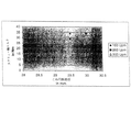
図4は隙間幅或いはこね円板直径と必要なスクリュ−トルクとの間の関係を示す。減少するこね円板直径Dにより、即ちこね円板カムとケ−シング内壁との間の増加する隙間幅により必要なスクリュ−軸トルクとそれによる伝達するエネルギ−が減少することを認識する。意外なことに、最終製品の分散は実際的に変更されないままである。
【0063】
スクリュ−軸トルクの回転数との僅かな依存性は同様に明らかである。100回/分から300回/分までの範囲において回転数の上昇を伴う必要なトルクが減少する。例えば300回/分の回転数の際にこね円板直径Dの1.5mmだけの減少によって、即ち隙間幅Zの0.75mmだけの増加によってこね円板の各カムを介してスクリュ−軸トルクの減少は28Nmから15Nmに測定される。
【0064】
図5はこの発明によるこね円板8を有する環状押出機30のその長手方向軸線と垂直である断面を示す。この環状押出機は12個の同じ方向に回転するスクリュ−軸33を含有する。この断面ではそれぞれ一個のそれぞれスクリュ−軸33に組み立てられたこね円板8が存在し、その円板のカム8a,8bは押出機30のケ−シング内壁9により隙間幅Zの隙間を形成し、その隙間はこね円板直径Dのおよそ1/10である。押出機30は内側に位置するコア冷却部32並びに外側に位置するケ−シング冷却部31を有する。
【図面の簡単な説明】
【図1】
この発明による押出機の概略的側面図を示す。
【図2aと図2b】
二つの異なる態様用の押出機スクリュ−の異なる地帯のそれぞれの概略図を示す。
【図3aと図3b】
二つのこね要素からこの発明によるこねブロックの側面図或いは軸方向図を示す。
【図4】
隙間幅或いはこね円板直径と必要なスクリュ−トルクとの間の関係を示すダイアグラムを示す。
【図5】
この発明によるこね円板を有する押出機のその長手方向軸線と垂直である断面を示す。
【符号の説明】
1.....押出機ケ−シング
1a,1b...搬入側端,搬出側端
2.....注入領域/搬送領域(ケ−シング1に関して)
2a,2b,2c...搬入側,中央,搬出側部分領域
3,3 .....スクリュ−軸
4.....こね地帯(ケ−シング1に関して)
5.....モ−タ/歯車装置ブロック
6.....分散地帯(ケ−シング1に関して)
2’,2”...注入部分(スクリュ−軸3,3 に関して)
4’,4”...こね部分(スクリュ−軸3,3 に関して)
6’,6”...分散部分(スクリュ−軸3,3 に関して)
7,7’,7”...貯蔵容器
8,10...こね要素/こね円板
8a,8b,10a,10b...カム
9.....ケ−シング内壁
8c,10c...内歯
12....調合ユニット
13,14,15...調合導管
12,13,14,15...調合装置
16,18...放出開口
41,42,43... ..スクリュ−軸3上のこね円板(こねブロック)
61,62,63... ..スクリュ−軸3上の分散円板(こねブロック)
41 ,42 ,43 ... ..スクリュ−軸3 上のこね円板(こねブロック)
61 ,62 ,63 ... ..スクリュ−軸3 上の分散円板(こねブロック)
30....環状押出機
31....ケ−シング冷却部
32....コア冷却部
[0001]
The present invention relates to a multiscrew extruder according to claim 1 and a method according to claim 21 for reclaiming and / or processing an elastomer mixed with fillers, for example rubber with soot.
[0002]
[Prior art]
Multi-stage, discontinuous process steps are known for regenerating rubber mixtures. Regeneration of the rubber takes place in approximately two passes on a batch mixture with 250-500 l of contents in a mixing cycle of approximately 2-3 minutes. Subsequent shaping is performed by a roller mechanism (for tires) or an extruder (for side surfaces, etc.). The high cost of the structure and equipment of the mixing hole as well as the high cost of its operation make it difficult to reduce production costs.
[0003]
Over the years, the rubber industry has attempted to simplify processing. The continuous regeneration of rubber has been regarded as a possible solution for several years, as it is known, for example, in thermoplastic synthetic resins. Humans expect the following main benefits in a continuous manner:
Low vibration (especially quality) and product loss, extensive automation methods, low energy consumption, low air pollution.
[0004]
Continuous regeneration of rubber has been the desire of the rubber industry for several years. Continuous mixing methods suitable for rubber regeneration rely on the continuous compounding of all mixed compositions as well as the correct mixing of this component. Conventional conventional delivery forms, in which rubber is normally delivered in packages (natural or synthetic), have made economic continuous regeneration difficult. Powdered rubber has long been known, but was too expensive. New developments that allow for economical production of powdered rubber open up new possibilities in continuous rubber regeneration.
[0005]
Powdered rubber mixed with fillers has recently been obtained by continuous drying and filtration by co-precipitation between the rubber emulsion and the filler suspension. The powder rubber obtained in this way can be injected in a free stream.
[0006]
Current known methods of mixing rubber generally involve internal mixers with tangential or interengaging shank, cutting mills with impact mixers and / or packings mixed before cooling takes place in a batch-off device. A batch-off rolling mill is used to cut the mixture obtained by homogenizing the mixture into rolled sheets or feed strips.
[0007]
Alternatively, humans use melt extruders and roller die equipment.
[0008]
In order to ensure a good dispersion of the mixture without too much heating or a danger of initiating the mixing, it is often necessary to carry out a two-stage mixing process when mixing the individual fillers, in particular with high hardness or high hardness. A two-stage mixing process is required when mixing with high values of the Muney viscosity. The mixing of articles with low hardness requires extended mixing times and multiple passes of mixing to ensure good polymer dispersion.
[0009]
Today's mixed practices are capital intensive and result in high energy and operating costs. In addition, an unstable product quality crisis always arises, not only because of the large rubber packages differing in package density, but also because of the nature of these operations of mixed production in individual filling. It is variable and includes a number of processing steps.
[0010]
The internal mixer (or kneader) is still the central assembly in the production of rubber mixtures. In the internal mixer, two mechanical blades rotate, the geometry of which is aligned so that simultaneous axial and radial movement or mixing of the mixture takes place. Conventionally, the kneading blades rotate at different speeds, in opposite directions and with a more recent internal mixer mesh.
[0011]
Internal mixers are available in values from 1 liter to 450 liters (experimental machine) (tire kneader). The latter spans multiple layers and requires multiple million Franken (Swiss francs).
[0012]
The injection opening is located in the blade gap. The openings are closed by a hydraulically operated stamp during mixing. The stamping pressure from 2 bar to 10 bar compresses the mixture in the original mixing chamber and prevents discharge. The mixing time is typically 2 minutes.
[0013]
The mixing chamber includes a cooling hole in the wall. The kneading blade is also perforated for cooling.
[0014]
The discharge opening in the floor of the mixing chamber is hydraulically sealed by a so-called sliding or pivoting saddle. The opening is quickly opened to a size sufficient for pivotally mounted saddles, thereby allowing for rapid release.
[0015]
The drive of the internal mixer is provided by higher efficiency electric motors of up to 10 kW per kg. Modern internal mixers are capable of continuously adjusting blade speed.
[0016]
The charging of the internal mixer takes place semi-automatically by means of a so-called schedule switching device. The injectable filler is automatically discharged from the filler device (container, silo or flexible large bag) like soot, metered and fed to the internal mixer. Frequently changing small quantities and ball rubber are weighed manually after grinding in a ball cutter. The components previously weighed during manual weighing are fed to a kneader shaft.
[0017]
After the rubber, the filler and the additive are supplied in common, and finally the fluid component (plasticizer) is injected.
[0018]
The rubber is heated and plasticized in the first phase at a low rotational speed of the mixing process. Thereafter, the mixing operation is started (distributively and dispersively) at high rpm. A limiting factor in the mixing operation is temperature. The mass temperature and power consumption of the kneader drive are measured to monitor and control the mixing process. Both together provide a characteristic image that must be reconstructed from cycle to cycle to obtain a homogeneous blending characteristic. The finished mixture falls from the internal mixer to a mixing mill or cooling mill with an on-floor mixer where it is withdrawn as a continuous sheet, cooled in a batch-off device, cooled with a release agent, dried and finally stripped. And placed on a pallet.
[0019]
An important sub-step in the processing of elastomers such as rubber is to mix the rubber with a filler such as soot or silica. With this filler physical properties can be achieved and modified. Thus, a significant increase in tensile strength can be achieved, for example in styrene-butadiene rubber or in isoprene rubber (natural rubber) with a mass fraction of approximately 50-60% soot.
[0020]
In this first partial step, some kind of processing aid is usually used. Plasticizer oils are provided during rubber processing to reduce mixing viscosity and mixing elasticity. Thereby the powdered rubber is easily kneaded in the extruder and the soot is better dispersed in the rubber, i.e. crushed and distributed.
[0021]
For rubber production, it is necessary in other partial steps to crosslink the rubber chain molecules with one another. For this purpose, sulfur is mainly used. Alternatively, silicic acid, metal oxides or peroxides are used. Crosslinking in some elastomers can also be initiated by UV irradiation. The rubber chain molecules can be linked together by sulfur bridges, which results in high elasticity.
[0022]
Other additives may be used to improve the required product properties or may be used as processing aids, as stabilizers and the like.
[0023]
Conventional extrusion processes have always required high energy consumption which has sometimes led to thermal damage to the material to be processed.
[0024]
[Problems to be solved by the invention]
The object of the invention is to achieve a reduction in energy consumption during the regeneration and / or processing of the elastomer mixed with the filler without significant damage to the quality of the end product.
[0025]
[Means for Solving the Problems]
This task is solved by a multi-screw extruder according to claim 1 and a method according to claim 21.
[0026]
The gap according to the invention between the cam of the kneading element (kneading disk) of the extruder according to the invention and the casing inner wall allows a practically uniform distribution of the end product at the outlet of the extruder (i.e. the distribution rate and the crushing rate). Depending on the rotational speed of the screw and the selected gap width, a reduction of the screw torque and of the energy consumption by about half can be achieved. If necessary, the gap width measured in the radial direction of the axially extending gap between the kneading element cam of the extruder and the inner casing wall as a function of the axial position over the width of the kneading element or kneading disk. It is contemplated that it can be varied or that this gap width be constant along the axial direction over the entire width of the kneading element.
[0027]
In particular, the gap width and the rotational speed range of the shaft supporting the kneading element are measured so that a shear rate of approximately 10 / s to approximately 3000 / s, in particular between 30 / s and 1000 / s, is achieved. Have been.
[0028]
Furthermore, a further contribution of shearing the product can be achieved by a gap extending perpendicular to the axial product transport direction of the continuous kneading disc.
[0029]
The compounding device for compounding the plasticizer and / or the additive in a purposeful manner is provided in the inlet end region of the injection zone, and especially the compounding device for compounding the plasticizer and / or the additive in the product conveying direction. Along the at least one sub-stream of the injection zone. In particular, the kneading zone / plastic zone and / or the dispersion zone have a discharge opening in their discharge area.
[0030]
In another preferred embodiment, the injection zone or the transport zone of the extruder has a water dispensing device. This makes it possible to add water to the product, cooling not only on its surface but also inside the product, whereby thermal product damage can be effectively prevented. The essential cooling action then occurs mainly due to the heat of vaporization of the steam leaking through the discharge openings.
[0031]
For preference, the kneading zone / plastic zone and the dispersion zone each have a number of (kneading blocks) offset kneading disks, the width of which is in particular approximately 1/6 of the diameter of the kneading disk. And one diameter. This pallet-like configuration is particularly well suited for screws which must often be adapted in different operating conditions. However, the kneading disc pallets can be formed in one piece, for example by casting or by mechanical working.
[0032]
The offset discs may be offset from each other by 90 degrees, or may be offset by less than 90 degrees in or against the direction of rotation. This achieves a neutral kneading action without a transport component or a kneading action with an overloaded return transport or transport component. However, with a suitable choice of this configuration, for example, a more or less powerful kneading and dispersing action can be achieved, in particular, targeted damming and pressure build-up before the discharge opening.
[0033]
In particular, a kneading disk is used in the kneading block of the screw kneading part and / or the dispersing part, the cam to cam diameter of the disk decreasing along the transport direction (increased gap width), or Increase (decrease gap width). In each zone, the product is transported or returned in the same manner, that is, dammed on the product.
[0034]
For convenience, the injection zone is at least as long as the sum of the lengths of the kneading zone / plastic zone and the dispersing zone, and has the preferred distributive or incoherent elements. This allows a good initial distribution of the product components without introducing large dispersing operations (milling). Above all, the injection zone of a distributively mixing length also gives the plasticizer sufficient time, firstly being well distributed and dispersed in the elastomer.
[0035]
As a multi-screw extruder, for example, an annular extruder with casing cooling as well as core cooling can be used. This allows a particularly effective cooling of the product, since heat is released into the extruder as well as into the annular working zone. Annular extruders offer distinct advantages over twin-screw extruders, especially as co-rotating and closely meshing multi-screw extruders. With an annular extruder, the inventor of the present application for continuous rubber regeneration must provide the only particularly preferred solution for rubber regeneration and must meet the following five main criteria:
Optimal mixing distribution (distributive mixing), small and narrow particle size distribution (dispersive mixing), lower energy consumption, gas release without thermal damage due to time-temperature-history.
[0036]
Based on higher special variables, such as cylinder surface and wedge-shaped surface, this criterion is achieved more efficiently with a ring extruder than with a conventional twin screw extruder.
[0037]
In particular, dispersive mixing is achieved quickly and gently with respect to the factor by means of a ring extruder. The reason lies in its small passive volume, its narrower target size distribution and its large special heat transfer surface.
[0038]
Thereby, the annular extruder is particularly suitable for regenerating rubber as a continuous processing machine.
[0039]
To this end, the extruder has shaping means at the discharge end, in particular with a pre-switched discharge device. For example, it can be processed into a final product in which powder rubber is formed in a row.
[0040]
Cam and casing of the kneading element such that operation of the shaft supporting the kneading element achieves a shear rate of approximately 10 / s to approximately 3000 / s, in particular between 30 / s and 1000 / s. It is ensured that there is sufficient shearing action to achieve sufficient kneading and dispersing action in the appropriate zone as achieved between the inner walls.
[0041]
The product obtained at the outlet of the extruder is a fluidly related mixture, which contains mainly elastomers (for example rubber) and fillers (for example soot or silica) and plasticizers (oil). Elastomer means a continuous (related) phase, and distributed and ground filler means a discontinuous phase of the mixture.
[0042]
Suitably, plasticizers and / or additives are compounded in the inlet end area of the dosing area, but are distributed and compounded as required along at least one partial area of the dosing area along the product transport direction. obtain.
[0043]
Alternatively, plasticizers and / or additives can be dispensed in the discharge end area of the injection area.
[0044]
Gases are also discharged, especially when mixing and mixing water in the region of the kneading / plasticizing region and / or the dispersion region, in particular in the region of the injection region.
[0045]
Especially if an annular extruder is used, the casing and the core of the multi-screw extruder are cooled, in particular.
[0046]
As appropriate, the product is delivered at the discharge end of the extruder, followed by shaping.
[0047]
In particular, if an elastomer starting material (powder rubber) is used, the material already contains some of the additives and / or plasticizers (soot), and the state of dispersion in the elastomer is increased by the method according to the invention. Is done.
[0048]
BEST MODE FOR CARRYING OUT THE INVENTION
Other advantages, features and possible uses of the invention will become apparent from the following description of an embodiment thereof, based on the drawings. FIG. 1 shows a schematic side view of an extruder according to the invention, FIGS. 2a and 2b show respective schematic views of different zones of extruder screws for two different embodiments, and FIGS. 3a and 3b show two views. FIG. 4 shows a side view or an axial view of a kneading block according to the invention from two kneading elements, FIG. 4 shows a diagram showing the relationship between the gap width or the diameter of the kneading disc and the required screw torque, and FIG. 1 shows a cross section of an extruder having a kneaded disk according to the invention, which is perpendicular to its longitudinal axis.
[0049]
FIG. 1 shows an extruder according to the invention in a schematic side view. In an extruder, an elastomer, such as powdered rubber, mixed with a filler, such as soot or silica, is regenerated or processed with the goal of grinding and uniformly distributing the soot particles in the powdered rubber. Dispersion (degree of grinding and distribution of soot particles) is a good feature of the final product.
[0050]
The extruder is a pair of screws-3 or a pair of screws-3 * (See FIG. 2). Screw-3 or 3 * Are driven by the motor / gear unit block 5 of the extruder. The extruder casing 1 includes a kneading zone 4 and a dispersing zone 6 in the conveying direction (from left to right) of the row after the injection zone 2. The powdered rubber is supplied from the storage container 7 to the extruder casing 1 at the carry-in end 1a.
[0051]
For example, a plasticizer such as oil is supplied from the storage container 7 ′ via the blending unit 12 and the blending conduit 13 to the inlet side partial area 2 a of the injection area 2. Alternatively, a plasticizer can be distributed over the injection area 2 and supplied to the inlet, intermediate and outlet partial areas 2a, 2b, 2c of the injection area 2 by means of compounding conduits 13, 14 and 15, respectively. Is done.
[0052]
In the kneading zone 4 and the dispersing zone 6, the product is subjected to shearing action and through-mixing in order to pulverize and distribute soot or silica particles in the extruder casing 1 and the distribution takes place mainly in the kneading zone 4, Grinding is mainly performed in the dispersion area 6. Additives or water can be dispensed and mixed from another storage container 7 ". In the region of the kneading zone 4 and the dispersing zone 6, the extruder casing 1 has a discharge opening 16 or 18 respectively, which opening is provided. The water to be dispensed through and optionally the plasticizer are removed from the product before it leaves the extruder casing 1 at its discharge end 1b.
[0053]
FIG. 2a is a schematic view of an extruder casing 1 having an injection zone 2, a kneading zone 4 and a dispersion zone 6. FIG. The product transport direction is indicated by arrow A.
[0054]
FIG. 2b shows two embodiments of screw-3 or 3 * which are arranged in the extruder casing 1 at least two parallel and partially in engagement with each other . Is schematically shown.
[0055]
Screw-3 (first embodiment) is composed of an injection part 2 ', a kneading part 4' and a dispersion part 6 'in the row conveying direction. The injection or conveying part 2 'of the screw 3 has non-meshing distributed elements. Here, the first mixing is performed simultaneously with the transport of the product. There is a screw element with a reduced passage height (not shown) and a kneading block, with one side being conveyed in a continuous kneading section 4 'to increase the pressure on the product and the kneading element 41 being aligned with one another. , 42, 43, etc., firstly exert a shearing effect on the product. There is also a one-sided conveying screw element with a reduced passage height (not shown) and a kneading block in the continuous dispersing part 6 ', which screw element is made up of the kneading disks 61, 62, 63 etc. aligned with one another. Establish (illustrated schematically). The action of the screw element and the kneading block is here the same as that of the part 4 '.
[0056]
Screw-3 * (Second embodiment) is configured similarly to Screw-3, but with a short injection portion 2 *. , Long kneaded part 4 * And long dispersion part 6 * Having. In particular, part 4 * And 6 * The kneading block consists of many kneading disks 41 * , 42 * , 43 * Or 61 * , 62 * , 63 * Etc.
[0057]
For screw-3 and screw-3 * Also in this case, there is a gap between the meshing portions 8a, 8b, 10a, 10b of the kneading disks 8, 10 (see FIGS. 3a, 3b) and the casing inner wall 9 of the extruder casing 1, and The gap width Z is in a range from about 1/100 to about 1/10 of the diameter D of the kneading disk.
[0058]
In the case of screw-3, the kneading part 4 'is assembled with a (neutral) kneading disc which is displaced by 90 degrees in the carry-in area and is displaced by less than 90 degrees in the rotational direction in the carry-out area ( And the kneading block of the dispersing part 6 'has only a neutral kneading disk.
[0059]
Screw-3 * In the case of kneaded part 4 * Is a kneading disc assembled with a deviation of less than 90 degrees in the carry-in side opposite to the rotation direction (conveyance) and a kneading disc assembled with a deviation of less than 90 degrees in the rotation direction in the unloading side (return conveyance) It contains connector block having, distributed portions 6 * The kneading block has only a neutral kneading disk. But here, unlike screw-3, kneading part 4 * And dispersion part 6 * The kneading blocks each have a kneading disc with a larger diameter in their carry-in area and in the carry-out area, i.e., the gap between the meshing part of the kneading disc and the casing inner wall extends along the product transport direction. To increase. This arrangement works similarly.
[0060]
FIG. 3a shows a kneading block consisting of two kneading disks 8, 10 which are arranged rotated by 90 degrees about the screw axis and are observed in the radial direction. The width B of the kneading disks 8, 10 is approximately half the diameter D of the kneading disks, and the diameter of the kneading disks 8, 10 as the "maximum diameter" is from the cam 8a to the cam 8b or from the cam 10a to the cam 10b. Should be grasped.
[0061]
FIG. 3b shows the kneaded block of FIG. 3a observed in the axial direction. Here, the internal teeth 10c are recognizable, so that the kneading disks 8, 10 can be assembled integrally with the external teeth of the screw shaft (not shown) displaced circumferentially by a certain number of teeth. .
[0062]
FIG. 4 shows the relationship between the gap width or the diameter of the tongue and the required screw torque. It is recognized that the required screw shaft torque and the energy transmitted thereby are reduced by the reduced tongue disk diameter D, i.e. by the increasing gap width between the tongue disk cam and the inner casing wall. Surprisingly, the distribution of the final product remains practically unchanged.
[0063]
The slight dependence of the screw shaft torque on the rotational speed is likewise evident. In the range from 100 times / minute to 300 times / minute, the required torque accompanying an increase in the rotational speed decreases. For example, at a speed of 300 revolutions per minute, the screw shaft torque is reduced via the cams of the kneading disc by a reduction of the kneading disc diameter D by 1.5 mm, ie by an increase of the gap width Z by 0.75 mm. Is measured from 28 Nm to 15 Nm.
[0064]
FIG. 5 shows a cross section of an annular extruder 30 having a kneading disk 8 according to the invention, which is perpendicular to its longitudinal axis. This annular extruder contains twelve co-rotating screw shafts 33. In this cross section, there is a kneading disk 8 assembled on one screw shaft 33, and the cams 8a and 8b of the disks form a gap having a gap width Z by the inner casing 9 of the extruder 30. The gap is about 1/10 of the diameter D of the kneaded disk. The extruder 30 has an inner core cooling unit 32 and an outer casing cooling unit 31.
[Brief description of the drawings]
FIG.
1 shows a schematic side view of an extruder according to the invention.
2a and 2b
Figure 3 shows a schematic view of each of the different zones of the extruder screw for two different embodiments.
3a and 3b
FIG. 2 shows a side view or an axial view of a kneading block according to the invention from two kneading elements.
FIG. 4
2 shows a diagram illustrating the relationship between the gap width or the diameter of the tongue and the required screw torque.
FIG. 5
1 shows a cross section of an extruder having a kneaded disk according to the invention, which is perpendicular to its longitudinal axis.
[Explanation of symbols]
1. . . . . Extruder casings 1a, 1b. . . 1. Loading end, unloading end . . . . Injection area / transport area (for case 1)
2a, 2b, 2c. . . Incoming, central, and unloading side partial areas 3, 3 * . . . . . Screw shaft4. . . . . Kneading zone (in case 1)
5. . . . . Motor / gear unit block 6. . . . . Decentralized zone (for case 1)
2 ', 2 "... injection part (screw shaft 3, 3 * About)
4 ', 4 "... kneaded part (screw shaft 3, 3 * About)
6 ', 6 "... dispersing part (screw shafts 3, 3 * About)
7, 7 ', 7 "... storage container 8, 10, ... kneading element / kneading disk 8a, 8b, 10a, 10b ... cam 9 ... inner casing 8c, 10c ... Internal teeth 12 ... Mixing units 13, 14, 15, ... Mixing conduits 12, 13, 14, 15, ... Mixing device 16, 18, ... Discharge openings 41, 42, 43 ... Kneading disk (kneading block) on screw shaft 3
61, 62, 63. . . . . Dispersion disk (kneading block) on screw shaft 3
41 * , 42 * , 43 * . . . . . Screw shaft 3 * Knead disk on top (kneaded block)
61 * , 62 * , 63 * . . . . . Screw shaft 3 * Upper dispersion disk (kneading block)
30. . . . Annular extruder 31. . . . Casing cooling section 32. . . . Core cooling section

Claims (30)

充填材と混合したエラストマ−、特に少なくとも一つの可塑剤及び/又は添加物をもつ弾性ゴムを再生及び/又は加工し、押出機が製品輸送の方向に連続してエラストマ−並びに可塑剤及び/又は添加物が調合される注入地域(2)と、エラストマ−が可塑剤及び/又は添加物と共に流動性関連混合物(複合物)に移行される少なくとも一つのこね要素(8、10)を備えるこね/可塑地域(4)と、エラストマ−内の充填材が粉砕されて分配される少なくとも一つの他のこね要素(8、10)を備える分散地域(6)とを有し、少なくとも二つの軸を備える多軸押出機において、こね要素(8、10)のカム(8a,8b,10a,10b)と押出機のケ−シング内壁(9)との間にこね要素直径Dのおよそ1/100からおよそ1/10までの隙間幅Zをもつ隙間が存在することを特徴とする多軸押出機。Regenerate and / or process the elastomer mixed with the filler, in particular the elastic rubber with at least one plasticizer and / or additive, and the extruder continuously in the direction of product transport the elastomer and the plasticizer and / or A kneader comprising an injection area (2) in which the additive is dispensed and at least one kneading element (8, 10) in which the elastomer is transferred together with the plasticizer and / or the additive into a flow-related mixture (composite) / It has a plasticizing zone (4) and a dispersing zone (6) with at least one other kneading element (8, 10) in which the filler in the elastomer is crushed and distributed, comprising at least two shafts. In the multi-screw extruder, between the cam (8a, 8b, 10a, 10b) of the kneading element (8, 10) and the casing inner wall (9) of the extruder about 1/100 to about 1/100 of the kneading element diameter D. 1/10 Multi-screw extruder, characterized in that a gap is present having a gap width Z in. こね要素を支持する軸の隙間幅と回転数範囲はおよそ10/sからおよそ3000/sまでの剪断率が好ましくは30/sと1000/sの間に達成されるように測定されていることを特徴とする請求項1に記載の押出機。The gap width and rotational speed range of the shaft supporting the kneading element are measured such that a shear rate of about 10 / s to about 3000 / s is achieved, preferably between 30 / s and 1000 / s. The extruder according to claim 1, wherein: 可塑剤及び/又は添加物を調合する調合装置(12、13)は注入地域(2)の搬入側端範囲(2a)に設けられていることを特徴とする請求項1或いは請求項2に記載の押出機。3. The plasticizer and / or additive compounding device (12, 13) is provided in the inlet end area (2a) of the injection area (2). Extruder. 可塑剤及び/又は添加物を調合する調合装置(12、13、14、15)は製品搬送方向に沿って注入地域(2)の少なくとも一つの部分範囲(2a,2b,2c)の上に分配して設けられていることを特徴とする請求項1乃至請求項3のいずれか一項に記載の押出機。A dispensing device (12, 13, 14, 15) for dispensing plasticizers and / or additives dispenses along at least one sub-region (2a, 2b, 2c) of the injection zone (2) along the product transport direction. The extruder according to any one of claims 1 to 3, wherein the extruder is provided. こね/可塑地域(4)及び/又は分散地域(6)がそれぞれ一つの放出開口(16、18)を有することを特徴とする請求項1乃至請求項4のいずれか一項に記載の押出機。Extruder according to one of the preceding claims, characterized in that the kneading / plastic zone (4) and / or the dispersing zone (6) each have one discharge opening (16, 18). . 注入地域(2)或いは搬送範囲は一つの水調合供給装置を有することを特徴とする請求項5に記載の押出機。The extruder according to claim 5, characterized in that the injection area (2) or the conveying area has one water dispenser. こね/可塑地域(4)及び分散地域(6)がそれぞれに多数の軸方向に並列されたこね円板(41,42,43,...或いは61,62,63,...)から成る一つのこねブロックを有することを特徴とする請求項1乃至請求項6のいずれか一項に記載の押出機。The kneading / plastic zone (4) and the dispersion zone (6) each consist of a number of axially parallel kneading disks (41, 42, 43, ... or 61, 62, 63, ...). The extruder according to any one of claims 1 to 6, comprising one kneading block. こね円板の幅Bはこね円板(41,42,43,...或いは61,62,63,...)の直径Dのおよそ1/6と直径Dのおよそ1の間の範囲に位置することを特徴とする請求項7に記載の押出機。The width B of the kneading disk is in a range between approximately 1/6 of the diameter D of the kneading disk (41, 42, 43, or 61, 62, 63, ...) and approximately 1 of the diameter D. The extruder according to claim 7, wherein the extruder is located. 並列されたこね円板(41,42,43,...或いは61,62,63,...)がそれぞれに90度だけ互いにずれていることを特徴とする請求項7或いは請求項8に記載の押出機。9. The method according to claim 7, wherein the parallel-connected tongue disks (41, 42, 43,... Or 61, 62, 63,...) Are mutually offset by 90 degrees. The extruder as described. 並列されたこね円板が回転方向において90度より少なくずれている(後退して)か、或いは回転方向に逆らって90度より少なくずれている(前進して)配置されていることを特徴とする請求項7或いは請求項8に記載の押出機。The kneaded disks arranged side by side are displaced by less than 90 degrees in the direction of rotation (retreat) or are displaced by less than 90 degrees in the direction of rotation (forward). The extruder according to claim 7 or 8, wherein the extruder is used. こね部分(4’;4 )のこね円板(41,42,43, ...;41 ,42 ,43 ,...)の最大直径Dは製品搬送方向に沿って減少することを特徴とする請求項7乃至請求項10のいずれか一項に記載の押出機。Kneaded part (4 '; 4 * ) Kneaded disks (41, 42, 43, ...; 41 *) , 42 * , 43 * ,. . . 11) The extruder according to any one of claims 7 to 10, wherein the maximum diameter D of the extruder decreases in the product conveying direction. 分散部分(6’;6 )のこね円板(61,62,63,...;61 ,62 ,63 ,...)の最大直径Dは製品搬送方向に沿って減少することを特徴とする請求項7乃至請求項11のいずれか一項に記載の押出機。Dispersed part (6 ′; 6 * ) Kneaded disks (61, 62, 63, ...; 61 *) , 62 * , 63 * ,. . . 12) The extruder according to any one of claims 7 to 11, wherein the maximum diameter D of the extruder decreases in the product conveying direction. こね部分(4’;4 )のこね円板(41,42,43, ...;41 ,42 ,43 ,...)の最大直径Dは製品搬送方向に沿って増加することを特徴とする請求項7乃至請求項10のいずれか一項又は請求項12に記載の押出機。Kneaded part (4 '; 4 * ) Kneaded disks (41, 42, 43, ...; 41 *) , 42 * , 43 * ,. . . 13. The extruder according to any one of claims 7 to 10, wherein the maximum diameter D of the extruder increases in the product conveying direction. 分散部分(6’;6 )のこね円板(61,62,63,...;61 ,62 ,63 ,...)の最大直径Dは製品搬送方向に沿って増加することを特徴とする請求項7乃至請求項11のいずれか一項又は請求項13に記載の押出機。Dispersed part (6 ′; 6 * ) Kneaded disks (61, 62, 63, ...; 61 *) , 62 * , 63 * ,. . . The extruder according to any one of claims 7 to 11, wherein the maximum diameter D of the extruder increases in the product conveying direction. それぞれ一つのこね円板(41,42,43,....;41 ,42 ,43 ,....;61,62,63,..... ;61 ,62 ,63 ,....)の直径は種々の軸方向位置における幅に沿って異なっていることを特徴とする請求項1乃至請求項14のいずれか一項に記載の押出機。Each one of the kneaded disks (41, 42, 43, ...; 41 * , 42 * , 43 * ,. . . . 61, 62, 63,. . . . . ; 61 * , 62 * , 63 * ,. . . . An extruder according to any one of the preceding claims, characterized in that the diameter of ()) varies along the width at various axial positions. 注入地域(2)或いは搬送範囲はこね/可塑地域(4)と分散地域(6)の長さの和と少なくとも同じ長さであることを特徴とする請求項1乃至請求項15のいずれか一項に記載の押出機。16. The injection area (2) or the transport area is at least as long as the sum of the lengths of the kneading / plastic area (4) and the dispersion area (6). The extruder according to item. 注入地域(2)は分配的即ち緊密に噛み合わない要素を有することを特徴とする請求項1乃至請求項16のいずれか一項に記載の押出機。An extruder according to any of the preceding claims, characterized in that the injection area (2) has distributive or non-intermeshing elements. 多軸押出機がケ−シング冷却部並びにコア冷却部(31,32)を有する環状押出機(30)であることを特徴とする請求項1乃至請求項17のいずれか一項に記載の押出機。18. The extrusion device according to claim 1, wherein the multi-screw extruder is an annular extruder (30) having a casing cooling part and a core cooling part (31, 32). Machine. 押出機はその搬出側端において形削り手段を有することを特徴とする請求項1乃至請求項18のいずれか一項に記載の押出機。19. The extruder according to any one of claims 1 to 18, wherein the extruder has a shaping means at a discharge end thereof. 搬出側押出機端と形削り装置の間に配達装置が設けられていることを特徴とする請求項19に記載の押出機。20. The extruder according to claim 19, wherein a delivery device is provided between the discharge-side extruder end and the shaping device. 請求項1乃至請求項20のいずれか一項に記載の押出機によって、充填材と混合したエラストマ−、特に可塑剤及び/又は添加物をもつゴムを再生及び/又は加工する方法であって、エラストマ−並びに可塑剤及び/又は添加物を調合させる工程;少なくとも一つのこね要素により製品をこねて/可塑して、エラストマ−が可塑剤及び/又は添加物と共に流動性関連混合物の状態にもたらされる工程と;少なくとも一つの他のこね要素により製品を分散して、エラストマ−内の充填材が粉砕されて分配される工程を有する方法において、剪断率がおよそ10/sからおよそ3000/sまで、好ましくは30/sと1000/sの間にこね要素のカムと押出機のケ−シング内壁との間に達成されるようにこね要素を支持する軸を運転することを特徴とする方法。21. A method for regenerating and / or processing an elastomer, particularly a rubber with a plasticizer and / or additives, mixed with a filler, by means of the extruder according to any one of claims 1 to 20, Formulating the elastomer and plasticizer and / or additive; kneading / plasticizing the product with at least one kneading element to bring the elastomer together with the plasticizer and / or additive into a fluid-related mixture. Dispersing the product by at least one other kneading element to crush and dispense the filler in the elastomer, wherein the shear rate is from about 10 / s to about 3000 / s. Driving the shaft supporting the kneading element so as to be achieved between the cam of the kneading element and the casing inner wall of the extruder, preferably between 30 / s and 1000 / s. Wherein. 可塑剤及び/又は添加物は注入地域(2)の搬入側端領域(2a)において調合されることを特徴とする請求項21に記載の方法。22. The method according to claim 21, wherein the plasticizer and / or additives are formulated in the inlet end area (2a) of the injection area (2). 可塑剤及び/又は添加物は製品搬送方向に沿って注入地域(2)の少なくとも一つの部分領域(2a,2b,2c)の上に分布されて調合されることを特徴とする請求項21に記載の方法。22. The composition according to claim 21, wherein the plasticizer and / or additives are distributed and compounded along at least one sub-region (2a, 2b, 2c) of the injection zone (2) along the product transport direction. The described method. 可塑剤及び/又は添加物は製品搬送方向に沿って注入地域(2)の搬出側部分領域(2c)において調合されることを特徴とする請求項23に記載の方法。24. The method according to claim 23, wherein the plasticizer and / or the additives are dispensed in the outlet area (2c) of the injection area (2) along the product transport direction. こね/可塑地域(4)及び/又は分散地域(6)の範囲ではガスが排出されることを特徴とする請求項21乃至請求項24のいずれか一項に記載の方法。25. The method according to claim 21, wherein gas is exhausted in the region of the kneading / plastic zone (4) and / or the decentralized zone (6). 注入地域(2)の範囲では調合された水が混合されることを特徴とする請求項21乃至請求項25のいずれか一項に記載の方法。26. The method according to claim 21, wherein the dispensed water is mixed in the area of the injection area (2). 多軸押出機(30)のケ−シング並びにコアが冷却されることを特徴とする請求項18に記載の押出機の使用の下で請求項21乃至請求項26のいずれか一項に記載の方法。27. The method according to claim 21, wherein the casing and the core of the multi-screw extruder are cooled. Method. 押出機の搬出側端には製品が配達されることを特徴とする請求項21乃至請求項27のいずれか一項に記載の方法。28. The method according to any one of claims 21 to 27, wherein the product is delivered to the discharge end of the extruder. 製品の配達後に製品の形削りが行われることを特徴とする請求項28に記載の方法。29. The method of claim 28, wherein shaping of the product is performed after delivery of the product. 添加物及び/又は可塑剤は既に再生すべき、或いは加工すべきエラストマ−に一体化されていることを特徴とする請求項21乃至請求項29のいずれか一項に記載の方法。30. The method according to claim 21, wherein the additives and / or plasticizers have already been integrated into the elastomer to be regenerated or processed.
JP2002534060A 2000-10-10 2001-05-30 Method for regenerating and / or processing elastomer mixed with multi-screw extruder and filler Pending JP2004509793A (en)

Applications Claiming Priority (2)

Application Number Priority Date Filing Date Title
DE10050295A DE10050295A1 (en) 2000-10-10 2000-10-10 Multi-shaft extruder for processing rubber compounds with fillers and additives has a specified gap between the shaft kneading blocks and barrel wall
PCT/CH2001/000336 WO2002030652A1 (en) 2000-10-10 2001-05-30 Multi-screw extruder and method for treating and/or processing elastomers with added filler

Publications (1)

Publication Number Publication Date
JP2004509793A true JP2004509793A (en) 2004-04-02

Family

ID=7659373

Family Applications (1)

Application Number Title Priority Date Filing Date
JP2002534060A Pending JP2004509793A (en) 2000-10-10 2001-05-30 Method for regenerating and / or processing elastomer mixed with multi-screw extruder and filler

Country Status (7)

Country Link
US (1) US20040094862A1 (en)
EP (1) EP1324869B1 (en)
JP (1) JP2004509793A (en)
AT (1) ATE286805T1 (en)
AU (1) AU2001258144A1 (en)
DE (2) DE10050295A1 (en)
WO (1) WO2002030652A1 (en)

Cited By (1)

* Cited by examiner, † Cited by third party
Publication number Priority date Publication date Assignee Title
JP2014501188A (en) * 2010-12-27 2014-01-20 アルケマ フランス Method for extruding polymers in the presence of water

Families Citing this family (39)

* Cited by examiner, † Cited by third party
Publication number Priority date Publication date Assignee Title
DE10055772A1 (en) * 2000-11-10 2002-05-29 Buehler Ag Ring extruder intake
JP3868757B2 (en) * 2001-04-25 2007-01-17 株式会社神戸製鋼所 Rubber composition kneading apparatus and kneading method
DE10143570A1 (en) * 2001-09-05 2003-03-20 Buehler Ag Degassing of flowable masses in a multi-screw extruder
JP2005511340A (en) * 2001-09-14 2005-04-28 ビユーラア アクチエンゲゼルシヤフト Elastomer mixtures for rubber production
DE10150006A1 (en) * 2001-10-11 2003-04-17 Buehler Ag Ring extruder for processing powders, pellets or flock material has a conveyer screw element with a section which does not intermesh with a screw element on an adjacent screw shaft
US6890091B2 (en) * 2001-11-15 2005-05-10 Kobe Steel, Ltd. Kneading apparatus, including selectable discharge ports, for kneading rubber or rubber compositions
DE10208181A1 (en) * 2002-02-20 2003-08-28 Buehler Ag Multi-shaft extruder, especially for extruding rubber, has a structured feed of a mineral oil softener into the extruder at different points and at different times
DE10211673A1 (en) * 2002-03-15 2003-09-25 Buehler Ag Multi-shaft extruder for thermoplastics or elastomers comprises process chamber formed by parallel recesses with outlet end of cylindrical part chambers in which conveying screws are located
DE10317357B4 (en) * 2003-04-15 2006-10-26 3+Extruder Gmbh extruder
EP1508424B2 (en) 2003-08-22 2016-10-26 Coperion GmbH Screw machine having mixing and kneading discs
US7655728B2 (en) * 2005-06-27 2010-02-02 Exxonmobil Chemical Patents Inc. Preparation of thermoplastic elastomers by dynamic vulcanization in multi-screw extruders
US8653170B2 (en) * 2005-06-27 2014-02-18 Exxonmobil Chemical Patents Inc. Dynamic vulcanization process for preparing thermoplastic elastomers
DE102006014692B3 (en) * 2006-03-28 2007-08-02 Berstorff Gmbh Kneading assembly for plastic and rubber compounds has two or more discrete kneading stations on a single helical spindle
JP4834653B2 (en) * 2007-12-19 2011-12-14 株式会社神戸製鋼所 Kneading screw and extruder
DE102008012185A1 (en) * 2008-03-03 2009-09-10 Tesa Se Process for the preparation of a highly cohesive PSA
RU2457944C1 (en) * 2008-07-08 2012-08-10 Пирелли Тайр С.П.А. Multiscrew extruder for production of elastomer compositions
CN102089138B (en) * 2008-07-08 2013-08-14 倍耐力轮胎股份公司 Multiscrew extruder device for the production of elastomeric compounds
EP2379294B9 (en) * 2008-12-23 2013-11-13 Pirelli Tyre S.P.A. Process and plant for producing tyres
KR20110111536A (en) 2009-02-05 2011-10-11 리스트 홀딩 아게 Thermal seperation of material mixtures by way of a main vaporation and a dega-sification in seperate mixing kneaders
WO2011077330A1 (en) 2009-12-22 2011-06-30 Pirelli Tyre S.P.A. Extrusion process and device for producing elastomeric compounds
US20110146884A1 (en) * 2009-12-23 2011-06-23 Gary Robert Burg Continuous mixing system and apparatus
US20110178205A1 (en) * 2010-01-18 2011-07-21 Martin Weber Process for producing thermoplastic molding compositions based on styrene copolymers and polyamide with improved toughness
EP2655029B1 (en) 2010-12-22 2017-08-02 Pirelli Tyre S.p.A. Method for producing tyres
JP5693269B2 (en) * 2011-02-02 2015-04-01 株式会社神戸製鋼所 Kneading segment and kneading equipment
US20130163368A1 (en) 2011-12-22 2013-06-27 Marie-Laure Stéphanie Milan Apparatus and process for mixing rubber compounds
US20130161857A1 (en) * 2011-12-22 2013-06-27 Marie-Laure Stéphanie Milan Apparatus and process for mixing rubber compounds
CN104736317B (en) 2012-10-11 2017-09-22 恩特克斯拉斯特及米施克有限责任公司 The extruder for the plastics being easily bonded for processing
DE102013208445A1 (en) * 2013-05-08 2014-11-13 Tesa Se Process for producing a syntactically foamed polymer composition, preferably a pressure-sensitive adhesive, apparatus for carrying out the method, extrudate and self-adhesive tape
CN103737890A (en) * 2013-12-30 2014-04-23 南京诚盟机械有限公司 Ultrahigh-torque co-rotating parallel twin-screw extruder
CN104139509B (en) * 2014-07-11 2016-05-25 玉石塑粉有限公司 For the production of the double screw extruder of powdery paints
CN105599167A (en) * 2016-02-05 2016-05-25 北京万向新元科技股份有限公司 Extruding dewatering granulator for producing rubber compound by wet method
DE102016002143A1 (en) 2016-02-25 2017-08-31 Entex Rust & Mitschke Gmbh Filling module in planetary roller extruder design
CN107263841B (en) * 2017-06-22 2019-04-16 枝江市顺达顺塑料制品有限公司 A kind of extrusion moulding apparatus with uniform stirring plastics
DE102017006638A1 (en) 2017-07-13 2019-01-17 Entex Rust & Mitschke Gmbh Filling module in planetary roller extruder design
FR3066135B1 (en) * 2017-12-22 2019-08-09 Sidel Participations PRODUCTION OF CONTAINERS WITH BIVIS EXTRUDER RECYCLING
WO2019166125A1 (en) 2018-02-28 2019-09-06 Entex Rust & Mitschke Gmbh Method for producing and processing polymers and polymer mixtures in a modular planetary roller extruder
CN108638371B (en) * 2018-05-03 2020-06-05 青岛凯东工业有限公司 New material production agitating unit
CN108548448B (en) * 2018-05-11 2023-05-16 沈阳工程学院 Device and method for online monitoring and automatic ball supplementing of rubber ball quantity based on ultrasonic sensing technology
CN110802758B (en) * 2019-10-30 2021-07-23 青岛科技大学 Production equipment and production method for gas-assisted injection rubber wet-process rubber compound

Citations (11)

* Cited by examiner, † Cited by third party
Publication number Priority date Publication date Assignee Title
JPH04276407A (en) * 1990-12-14 1992-10-01 Hermann Berstorff Mas Gmbh Method and device for continuously producing in onestep and with one mixing device rubber base mixture and rubber finish mixture for automobile tire, drive belt, conveyor belt and industrial rubber product
JPH05505773A (en) * 1990-03-28 1993-08-26 シュラウフシュテッテル・ウイルフリート Processing method for reprocessing rubber-containing waste
JPH0976324A (en) * 1995-09-18 1997-03-25 Mitsubishi Chem Corp Manufacture of deodorized thermoplastic polymer
JPH09117954A (en) * 1995-10-25 1997-05-06 Toshiba Mach Co Ltd Twin-screw extruder
JPH10231379A (en) * 1997-02-17 1998-09-02 Kishimoto Sangyo Kk Foamable master batch and its production
JPH1110708A (en) * 1997-06-24 1999-01-19 Toshiba Mach Co Ltd Kneading method for highly lubricating material using double-screw extruder
JPH1171466A (en) * 1997-08-28 1999-03-16 Asahi Chem Ind Co Ltd Preparation of resin composition
JPH11188775A (en) * 1997-12-26 1999-07-13 Asahi Chem Ind Co Ltd Extruder and extruding method using that
JP2000037764A (en) * 1998-07-23 2000-02-08 Asahi Chem Ind Co Ltd Extrusion machine and method using the machine
JP2000117728A (en) * 1998-10-13 2000-04-25 Josef A Blach Continuous processing machine for fluidizable material
JP2000505377A (en) * 1996-02-29 2000-05-09 フリチュ、ローゼマリー イー. Multi screw machine

Family Cites Families (13)

* Cited by examiner, † Cited by third party
Publication number Priority date Publication date Assignee Title
DE3014643A1 (en) * 1980-04-16 1981-10-22 Bayer Ag, 5090 Leverkusen SIMPLY ROTATABLE DOUBLE SNAIL
US4663103A (en) * 1983-08-09 1987-05-05 Collins & Aikman Corporation Apparatus and method of extrusion
DE3841728C1 (en) * 1988-12-10 1990-03-01 Hermann Berstorff Maschinenbau Gmbh, 3000 Hannover, De
US5158725A (en) * 1991-04-29 1992-10-27 The Goodyear Tire & Rubber Company Continuous mixing of elastomeric compounds
DE4122912A1 (en) * 1991-07-11 1993-01-14 Theysohn Friedrich Fa DOUBLE SCREW EXTRUDER
DE4301431C2 (en) * 1992-02-27 1996-03-14 Mitsubishi Heavy Ind Ltd Two-stage extruder
DE4228016C1 (en) * 1992-08-24 1994-03-31 Biotec Biolog Naturverpack Process for producing biodegradable films from vegetable raw materials
JP2909577B2 (en) * 1993-10-29 1999-06-23 トヨタ自動車株式会社 Resin waste material recycling method and apparatus
JP3168450B2 (en) * 1995-09-29 2001-05-21 住友化学工業株式会社 Method for producing thermoplastic elastomer composition
ATE181867T1 (en) * 1996-02-06 1999-07-15 Josef A Blach DEVICE FOR CONTINUOUS PROCESSING OF FLOWING MATERIALS
US6472460B1 (en) * 1998-03-30 2002-10-29 Kabushiki Kaisha Toyota Chuo Kenkyusho Polymer composite material and process for preparing the same
US6116770A (en) * 1998-10-02 2000-09-12 Krupp Werner & Pfleiderer Corporation Mixing element for screw extruder
US6170975B1 (en) * 1999-02-08 2001-01-09 Krupp Werner & Pfleiderer Multi-shaft extruder kneading discs, kneading disc blocks and extruder

Patent Citations (11)

* Cited by examiner, † Cited by third party
Publication number Priority date Publication date Assignee Title
JPH05505773A (en) * 1990-03-28 1993-08-26 シュラウフシュテッテル・ウイルフリート Processing method for reprocessing rubber-containing waste
JPH04276407A (en) * 1990-12-14 1992-10-01 Hermann Berstorff Mas Gmbh Method and device for continuously producing in onestep and with one mixing device rubber base mixture and rubber finish mixture for automobile tire, drive belt, conveyor belt and industrial rubber product
JPH0976324A (en) * 1995-09-18 1997-03-25 Mitsubishi Chem Corp Manufacture of deodorized thermoplastic polymer
JPH09117954A (en) * 1995-10-25 1997-05-06 Toshiba Mach Co Ltd Twin-screw extruder
JP2000505377A (en) * 1996-02-29 2000-05-09 フリチュ、ローゼマリー イー. Multi screw machine
JPH10231379A (en) * 1997-02-17 1998-09-02 Kishimoto Sangyo Kk Foamable master batch and its production
JPH1110708A (en) * 1997-06-24 1999-01-19 Toshiba Mach Co Ltd Kneading method for highly lubricating material using double-screw extruder
JPH1171466A (en) * 1997-08-28 1999-03-16 Asahi Chem Ind Co Ltd Preparation of resin composition
JPH11188775A (en) * 1997-12-26 1999-07-13 Asahi Chem Ind Co Ltd Extruder and extruding method using that
JP2000037764A (en) * 1998-07-23 2000-02-08 Asahi Chem Ind Co Ltd Extrusion machine and method using the machine
JP2000117728A (en) * 1998-10-13 2000-04-25 Josef A Blach Continuous processing machine for fluidizable material

Cited By (1)

* Cited by examiner, † Cited by third party
Publication number Priority date Publication date Assignee Title
JP2014501188A (en) * 2010-12-27 2014-01-20 アルケマ フランス Method for extruding polymers in the presence of water

Also Published As

Publication number Publication date
AU2001258144A1 (en) 2002-04-22
DE50105081D1 (en) 2005-02-17
ATE286805T1 (en) 2005-01-15
US20040094862A1 (en) 2004-05-20
EP1324869A1 (en) 2003-07-09
DE10050295A1 (en) 2002-04-11
EP1324869B1 (en) 2005-01-12
WO2002030652A1 (en) 2002-04-18

Similar Documents

Publication Publication Date Title
JP2004509793A (en) Method for regenerating and / or processing elastomer mixed with multi-screw extruder and filler
JP3180926B2 (en) Method and apparatus for the one-stage and continuous production of rubber-base and rubber-finishing mixtures for automotive tires, drive belts, conveyor belts and industrial rubber products in a single mixing device
US10131760B2 (en) Starter for the devulcanisation of scrap rubber
US8876511B2 (en) Metering feeder, and system and method for kneading and extruding material
JP3472391B2 (en) Twin screw extruder and extrusion method using the twin screw extruder
EP1316399B1 (en) Kneading apparatus
JP3816282B2 (en) Compound manufacturing method using biaxial continuous kneader
JP5659288B1 (en) Method for producing transparent resin composition containing polycarbonate resin and acrylic resin
TW201946754A (en) Production method for conductive composite material
WO2005118242A1 (en) Continuous kneading device and kneading system using the same
JP2546880B2 (en) Screw extruder
JP4968828B2 (en) Screw for resin extruder, resin extruder, and pellet manufacturing method
JP3963042B2 (en) Continuous kneader and rotor of continuous kneader
KR100688868B1 (en) Method and device for the continuous production of rubber mixtures
CN202146733U (en) Three-rotor continuous mixing machine set provided with triangularly-arranged rotors
CN102225315A (en) Three-rotor continuous mixing unit with rotors arranged in straight line
JP3530334B2 (en) Continuous kneader and rotor of continuous kneader
JP3689348B2 (en) Wood flour compound pellet granulation method and apparatus
JP2000280324A (en) Screw blade structure for biaxial extruder
CN102225316A (en) Three-rotor continuous mixing unit with rotors arranged triangularly
JP2003164746A (en) Kneading device for rubber or rubbery composition
JP3154953B2 (en) Method for producing compound pellets containing wood flour
WO2022239292A1 (en) Granulator, kneading regulation mechanism, and method for producing resin pellets
CN202212119U (en) Tri-rotor continuous mixing unit with linearly arranged rotors
Patel et al. Review of potential processing techniques for the encapsulation of wastes in thermoplastic polymers

Legal Events

Date Code Title Description
A621 Written request for application examination

Free format text: JAPANESE INTERMEDIATE CODE: A621

Effective date: 20080130

RD04 Notification of resignation of power of attorney

Free format text: JAPANESE INTERMEDIATE CODE: A7424

Effective date: 20100527

A977 Report on retrieval

Free format text: JAPANESE INTERMEDIATE CODE: A971007

Effective date: 20101126

A131 Notification of reasons for refusal

Free format text: JAPANESE INTERMEDIATE CODE: A131

Effective date: 20101221

A02 Decision of refusal

Free format text: JAPANESE INTERMEDIATE CODE: A02

Effective date: 20110719