JP2004508162A - Ultraviolet light emitting diode system and method - Google Patents
Ultraviolet light emitting diode system and method Download PDFInfo
- Publication number
- JP2004508162A JP2004508162A JP2002517431A JP2002517431A JP2004508162A JP 2004508162 A JP2004508162 A JP 2004508162A JP 2002517431 A JP2002517431 A JP 2002517431A JP 2002517431 A JP2002517431 A JP 2002517431A JP 2004508162 A JP2004508162 A JP 2004508162A
- Authority
- JP
- Japan
- Prior art keywords
- led
- processor
- ultraviolet
- light
- visible
- Prior art date
- Legal status (The legal status is an assumption and is not a legal conclusion. Google has not performed a legal analysis and makes no representation as to the accuracy of the status listed.)
- Pending
Links
- 238000000034 method Methods 0.000 title claims description 66
- 238000000746 purification Methods 0.000 claims abstract description 36
- 230000000694 effects Effects 0.000 claims description 28
- 239000000463 material Substances 0.000 claims description 21
- 238000007689 inspection Methods 0.000 claims description 18
- 241000238631 Hexapoda Species 0.000 claims description 17
- 230000001678 irradiating effect Effects 0.000 claims description 10
- 239000007788 liquid Substances 0.000 claims description 10
- 230000004044 response Effects 0.000 claims description 9
- 230000012010 growth Effects 0.000 claims description 8
- 230000008859 change Effects 0.000 claims description 6
- 239000003086 colorant Substances 0.000 claims description 5
- 230000005540 biological transmission Effects 0.000 claims description 3
- 230000000749 insecticidal effect Effects 0.000 claims description 3
- XLYOFNOQVPJJNP-UHFFFAOYSA-N water Substances O XLYOFNOQVPJJNP-UHFFFAOYSA-N 0.000 description 39
- 230000005855 radiation Effects 0.000 description 33
- 238000005286 illumination Methods 0.000 description 21
- 238000001228 spectrum Methods 0.000 description 19
- 241000271566 Aves Species 0.000 description 14
- 230000008635 plant growth Effects 0.000 description 13
- QSHDDOUJBYECFT-UHFFFAOYSA-N mercury Chemical compound [Hg] QSHDDOUJBYECFT-UHFFFAOYSA-N 0.000 description 12
- 230000008569 process Effects 0.000 description 12
- 229910052753 mercury Inorganic materials 0.000 description 11
- 238000004891 communication Methods 0.000 description 10
- 238000004659 sterilization and disinfection Methods 0.000 description 9
- 238000004519 manufacturing process Methods 0.000 description 8
- 230000003595 spectral effect Effects 0.000 description 8
- 230000001954 sterilising effect Effects 0.000 description 8
- 238000012360 testing method Methods 0.000 description 8
- 239000011521 glass Substances 0.000 description 7
- CURLTUGMZLYLDI-UHFFFAOYSA-N Carbon dioxide Chemical compound O=C=O CURLTUGMZLYLDI-UHFFFAOYSA-N 0.000 description 6
- 241000287828 Gallus gallus Species 0.000 description 6
- 230000033228 biological regulation Effects 0.000 description 6
- 235000013330 chicken meat Nutrition 0.000 description 6
- 230000006870 function Effects 0.000 description 6
- 230000003287 optical effect Effects 0.000 description 6
- 239000003973 paint Substances 0.000 description 6
- 241000700605 Viruses Species 0.000 description 5
- 238000004140 cleaning Methods 0.000 description 5
- 238000001514 detection method Methods 0.000 description 5
- 235000013601 eggs Nutrition 0.000 description 5
- 241000894006 Bacteria Species 0.000 description 4
- OAICVXFJPJFONN-UHFFFAOYSA-N Phosphorus Chemical compound [P] OAICVXFJPJFONN-UHFFFAOYSA-N 0.000 description 4
- 230000008901 benefit Effects 0.000 description 4
- 235000019987 cider Nutrition 0.000 description 4
- 239000000975 dye Substances 0.000 description 4
- 238000012986 modification Methods 0.000 description 4
- 230000004048 modification Effects 0.000 description 4
- 230000036961 partial effect Effects 0.000 description 4
- 238000001126 phototherapy Methods 0.000 description 4
- 238000011160 research Methods 0.000 description 4
- 241001465754 Metazoa Species 0.000 description 3
- 206010042496 Sunburn Diseases 0.000 description 3
- 230000001580 bacterial effect Effects 0.000 description 3
- 229910002092 carbon dioxide Inorganic materials 0.000 description 3
- 239000001569 carbon dioxide Substances 0.000 description 3
- 208000037265 diseases, disorders, signs and symptoms Diseases 0.000 description 3
- 238000005516 engineering process Methods 0.000 description 3
- 239000000835 fiber Substances 0.000 description 3
- 235000013305 food Nutrition 0.000 description 3
- 238000009928 pasteurization Methods 0.000 description 3
- 238000012545 processing Methods 0.000 description 3
- 239000004575 stone Substances 0.000 description 3
- 230000001225 therapeutic effect Effects 0.000 description 3
- 241000251468 Actinopterygii Species 0.000 description 2
- 241000938605 Crocodylia Species 0.000 description 2
- 239000004593 Epoxy Substances 0.000 description 2
- 241000282412 Homo Species 0.000 description 2
- 206010028980 Neoplasm Diseases 0.000 description 2
- CBENFWSGALASAD-UHFFFAOYSA-N Ozone Chemical compound [O-][O+]=O CBENFWSGALASAD-UHFFFAOYSA-N 0.000 description 2
- 238000004458 analytical method Methods 0.000 description 2
- 230000000844 anti-bacterial effect Effects 0.000 description 2
- 201000011510 cancer Diseases 0.000 description 2
- 239000004568 cement Substances 0.000 description 2
- 238000001816 cooling Methods 0.000 description 2
- 230000006378 damage Effects 0.000 description 2
- 238000011161 development Methods 0.000 description 2
- 201000010099 disease Diseases 0.000 description 2
- 239000003651 drinking water Substances 0.000 description 2
- 235000020188 drinking water Nutrition 0.000 description 2
- 235000013399 edible fruits Nutrition 0.000 description 2
- 230000005611 electricity Effects 0.000 description 2
- 238000002474 experimental method Methods 0.000 description 2
- 238000001914 filtration Methods 0.000 description 2
- 239000003292 glue Substances 0.000 description 2
- 229910052736 halogen Inorganic materials 0.000 description 2
- 150000002367 halogens Chemical class 0.000 description 2
- 239000002920 hazardous waste Substances 0.000 description 2
- 230000036541 health Effects 0.000 description 2
- 238000003384 imaging method Methods 0.000 description 2
- 230000006872 improvement Effects 0.000 description 2
- 239000000976 ink Substances 0.000 description 2
- 238000007726 management method Methods 0.000 description 2
- 201000001441 melanoma Diseases 0.000 description 2
- 239000007800 oxidant agent Substances 0.000 description 2
- 239000004065 semiconductor Substances 0.000 description 2
- 238000004088 simulation Methods 0.000 description 2
- 238000012414 sterilization procedure Methods 0.000 description 2
- 238000003860 storage Methods 0.000 description 2
- 230000009182 swimming Effects 0.000 description 2
- 238000009281 ultraviolet germicidal irradiation Methods 0.000 description 2
- 238000002211 ultraviolet spectrum Methods 0.000 description 2
- 238000001429 visible spectrum Methods 0.000 description 2
- 230000000007 visual effect Effects 0.000 description 2
- SGTNSNPWRIOYBX-UHFFFAOYSA-N 2-(3,4-dimethoxyphenyl)-5-{[2-(3,4-dimethoxyphenyl)ethyl](methyl)amino}-2-(propan-2-yl)pentanenitrile Chemical compound C1=C(OC)C(OC)=CC=C1CCN(C)CCCC(C#N)(C(C)C)C1=CC=C(OC)C(OC)=C1 SGTNSNPWRIOYBX-UHFFFAOYSA-N 0.000 description 1
- 206010006956 Calcium deficiency Diseases 0.000 description 1
- 206010007134 Candida infections Diseases 0.000 description 1
- 241000588724 Escherichia coli Species 0.000 description 1
- 206010015946 Eye irritation Diseases 0.000 description 1
- 208000001836 Firesetting Behavior Diseases 0.000 description 1
- 241000233866 Fungi Species 0.000 description 1
- 206010053759 Growth retardation Diseases 0.000 description 1
- 206010023126 Jaundice Diseases 0.000 description 1
- 208000004023 Legionellosis Diseases 0.000 description 1
- 241000124008 Mammalia Species 0.000 description 1
- 208000007027 Oral Candidiasis Diseases 0.000 description 1
- 241000237502 Ostreidae Species 0.000 description 1
- 201000004681 Psoriasis Diseases 0.000 description 1
- 241000283984 Rodentia Species 0.000 description 1
- 206010040880 Skin irritation Diseases 0.000 description 1
- 241000287411 Turdidae Species 0.000 description 1
- 229930003316 Vitamin D Natural products 0.000 description 1
- QYSXJUFSXHHAJI-XFEUOLMDSA-N Vitamin D3 Natural products C1(/[C@@H]2CC[C@@H]([C@]2(CCC1)C)[C@H](C)CCCC(C)C)=C/C=C1\C[C@@H](O)CCC1=C QYSXJUFSXHHAJI-XFEUOLMDSA-N 0.000 description 1
- 238000010521 absorption reaction Methods 0.000 description 1
- 239000000853 adhesive Substances 0.000 description 1
- 230000001070 adhesive effect Effects 0.000 description 1
- 238000004887 air purification Methods 0.000 description 1
- 235000013361 beverage Nutrition 0.000 description 1
- 230000000903 blocking effect Effects 0.000 description 1
- 239000008280 blood Substances 0.000 description 1
- 210000004369 blood Anatomy 0.000 description 1
- 210000003103 bodily secretion Anatomy 0.000 description 1
- 239000012482 calibration solution Substances 0.000 description 1
- 201000003984 candidiasis Diseases 0.000 description 1
- 239000002738 chelating agent Substances 0.000 description 1
- 238000006243 chemical reaction Methods 0.000 description 1
- 230000001427 coherent effect Effects 0.000 description 1
- 230000021615 conjugation Effects 0.000 description 1
- 238000011109 contamination Methods 0.000 description 1
- -1 cooling towers Substances 0.000 description 1
- 239000010730 cutting oil Substances 0.000 description 1
- 238000005034 decoration Methods 0.000 description 1
- 230000003247 decreasing effect Effects 0.000 description 1
- 210000003298 dental enamel Anatomy 0.000 description 1
- 239000000645 desinfectant Substances 0.000 description 1
- 230000018109 developmental process Effects 0.000 description 1
- 235000005911 diet Nutrition 0.000 description 1
- 230000037213 diet Effects 0.000 description 1
- 208000035475 disorder Diseases 0.000 description 1
- 238000009826 distribution Methods 0.000 description 1
- 239000003814 drug Substances 0.000 description 1
- 238000000295 emission spectrum Methods 0.000 description 1
- 230000002996 emotional effect Effects 0.000 description 1
- 230000007613 environmental effect Effects 0.000 description 1
- 125000003700 epoxy group Chemical group 0.000 description 1
- 231100000013 eye irritation Toxicity 0.000 description 1
- 239000012530 fluid Substances 0.000 description 1
- 239000007850 fluorescent dye Substances 0.000 description 1
- 239000006260 foam Substances 0.000 description 1
- 235000015203 fruit juice Nutrition 0.000 description 1
- 235000011389 fruit/vegetable juice Nutrition 0.000 description 1
- 230000002538 fungal effect Effects 0.000 description 1
- 239000004519 grease Substances 0.000 description 1
- 230000005802 health problem Effects 0.000 description 1
- 239000003501 hydroponics Substances 0.000 description 1
- 238000002169 hydrotherapy Methods 0.000 description 1
- 230000000670 limiting effect Effects 0.000 description 1
- 238000005259 measurement Methods 0.000 description 1
- 238000010339 medical test Methods 0.000 description 1
- 230000003340 mental effect Effects 0.000 description 1
- 230000000813 microbial effect Effects 0.000 description 1
- 235000013336 milk Nutrition 0.000 description 1
- 239000008267 milk Substances 0.000 description 1
- 210000004080 milk Anatomy 0.000 description 1
- 238000012806 monitoring device Methods 0.000 description 1
- 238000012544 monitoring process Methods 0.000 description 1
- 239000003921 oil Substances 0.000 description 1
- 210000000056 organ Anatomy 0.000 description 1
- 230000001151 other effect Effects 0.000 description 1
- 235000020636 oyster Nutrition 0.000 description 1
- 230000035515 penetration Effects 0.000 description 1
- 229910052698 phosphorus Inorganic materials 0.000 description 1
- 239000011574 phosphorus Substances 0.000 description 1
- 238000009372 pisciculture Methods 0.000 description 1
- 230000008121 plant development Effects 0.000 description 1
- 229920000647 polyepoxide Polymers 0.000 description 1
- 229920000642 polymer Polymers 0.000 description 1
- 230000008092 positive effect Effects 0.000 description 1
- 238000007639 printing Methods 0.000 description 1
- 238000004886 process control Methods 0.000 description 1
- 230000001737 promoting effect Effects 0.000 description 1
- 239000008213 purified water Substances 0.000 description 1
- 230000009467 reduction Effects 0.000 description 1
- 230000002829 reductive effect Effects 0.000 description 1
- 230000008439 repair process Effects 0.000 description 1
- 238000001223 reverse osmosis Methods 0.000 description 1
- 238000012552 review Methods 0.000 description 1
- 230000028327 secretion Effects 0.000 description 1
- 230000035945 sensitivity Effects 0.000 description 1
- 231100000475 skin irritation Toxicity 0.000 description 1
- 239000007787 solid Substances 0.000 description 1
- 239000000243 solution Substances 0.000 description 1
- 238000012358 sourcing Methods 0.000 description 1
- 239000007921 spray Substances 0.000 description 1
- 238000003756 stirring Methods 0.000 description 1
- 239000000126 substance Substances 0.000 description 1
- 238000010998 test method Methods 0.000 description 1
- 238000002560 therapeutic procedure Methods 0.000 description 1
- 238000011144 upstream manufacturing Methods 0.000 description 1
- 235000021419 vinegar Nutrition 0.000 description 1
- 239000000052 vinegar Substances 0.000 description 1
- 208000029257 vision disease Diseases 0.000 description 1
- 230000004393 visual impairment Effects 0.000 description 1
- 235000019166 vitamin D Nutrition 0.000 description 1
- 239000011710 vitamin D Substances 0.000 description 1
- 150000003710 vitamin D derivatives Chemical class 0.000 description 1
- 229940046008 vitamin d Drugs 0.000 description 1
- 239000002699 waste material Substances 0.000 description 1
- 239000002351 wastewater Substances 0.000 description 1
Images

Classifications
-
- C—CHEMISTRY; METALLURGY
- C02—TREATMENT OF WATER, WASTE WATER, SEWAGE, OR SLUDGE
- C02F—TREATMENT OF WATER, WASTE WATER, SEWAGE, OR SLUDGE
- C02F1/00—Treatment of water, waste water, or sewage
- C02F1/30—Treatment of water, waste water, or sewage by irradiation
- C02F1/32—Treatment of water, waste water, or sewage by irradiation with ultraviolet light
- C02F1/325—Irradiation devices or lamp constructions
-
- A—HUMAN NECESSITIES
- A61—MEDICAL OR VETERINARY SCIENCE; HYGIENE
- A61L—METHODS OR APPARATUS FOR STERILISING MATERIALS OR OBJECTS IN GENERAL; DISINFECTION, STERILISATION OR DEODORISATION OF AIR; CHEMICAL ASPECTS OF BANDAGES, DRESSINGS, ABSORBENT PADS OR SURGICAL ARTICLES; MATERIALS FOR BANDAGES, DRESSINGS, ABSORBENT PADS OR SURGICAL ARTICLES
- A61L2/00—Methods or apparatus for disinfecting or sterilising materials or objects other than foodstuffs or contact lenses; Accessories therefor
- A61L2/02—Methods or apparatus for disinfecting or sterilising materials or objects other than foodstuffs or contact lenses; Accessories therefor using physical phenomena
- A61L2/08—Radiation
- A61L2/10—Ultra-violet radiation
-
- A—HUMAN NECESSITIES
- A61—MEDICAL OR VETERINARY SCIENCE; HYGIENE
- A61L—METHODS OR APPARATUS FOR STERILISING MATERIALS OR OBJECTS IN GENERAL; DISINFECTION, STERILISATION OR DEODORISATION OF AIR; CHEMICAL ASPECTS OF BANDAGES, DRESSINGS, ABSORBENT PADS OR SURGICAL ARTICLES; MATERIALS FOR BANDAGES, DRESSINGS, ABSORBENT PADS OR SURGICAL ARTICLES
- A61L9/00—Disinfection, sterilisation or deodorisation of air
- A61L9/16—Disinfection, sterilisation or deodorisation of air using physical phenomena
- A61L9/18—Radiation
- A61L9/20—Ultra-violet radiation
-
- F—MECHANICAL ENGINEERING; LIGHTING; HEATING; WEAPONS; BLASTING
- F24—HEATING; RANGES; VENTILATING
- F24F—AIR-CONDITIONING; AIR-HUMIDIFICATION; VENTILATION; USE OF AIR CURRENTS FOR SCREENING
- F24F8/00—Treatment, e.g. purification, of air supplied to human living or working spaces otherwise than by heating, cooling, humidifying or drying
- F24F8/20—Treatment, e.g. purification, of air supplied to human living or working spaces otherwise than by heating, cooling, humidifying or drying by sterilisation
- F24F8/22—Treatment, e.g. purification, of air supplied to human living or working spaces otherwise than by heating, cooling, humidifying or drying by sterilisation using UV light
-
- H—ELECTRICITY
- H05—ELECTRIC TECHNIQUES NOT OTHERWISE PROVIDED FOR
- H05B—ELECTRIC HEATING; ELECTRIC LIGHT SOURCES NOT OTHERWISE PROVIDED FOR; CIRCUIT ARRANGEMENTS FOR ELECTRIC LIGHT SOURCES, IN GENERAL
- H05B45/00—Circuit arrangements for operating light-emitting diodes [LED]
- H05B45/20—Controlling the colour of the light
-
- A—HUMAN NECESSITIES
- A61—MEDICAL OR VETERINARY SCIENCE; HYGIENE
- A61L—METHODS OR APPARATUS FOR STERILISING MATERIALS OR OBJECTS IN GENERAL; DISINFECTION, STERILISATION OR DEODORISATION OF AIR; CHEMICAL ASPECTS OF BANDAGES, DRESSINGS, ABSORBENT PADS OR SURGICAL ARTICLES; MATERIALS FOR BANDAGES, DRESSINGS, ABSORBENT PADS OR SURGICAL ARTICLES
- A61L2202/00—Aspects relating to methods or apparatus for disinfecting or sterilising materials or objects
- A61L2202/10—Apparatus features
- A61L2202/16—Mobile applications, e.g. portable devices, trailers, devices mounted on vehicles
-
- A—HUMAN NECESSITIES
- A61—MEDICAL OR VETERINARY SCIENCE; HYGIENE
- A61L—METHODS OR APPARATUS FOR STERILISING MATERIALS OR OBJECTS IN GENERAL; DISINFECTION, STERILISATION OR DEODORISATION OF AIR; CHEMICAL ASPECTS OF BANDAGES, DRESSINGS, ABSORBENT PADS OR SURGICAL ARTICLES; MATERIALS FOR BANDAGES, DRESSINGS, ABSORBENT PADS OR SURGICAL ARTICLES
- A61L2202/00—Aspects relating to methods or apparatus for disinfecting or sterilising materials or objects
- A61L2202/20—Targets to be treated
- A61L2202/21—Pharmaceuticals, e.g. medicaments, artificial body parts
-
- A—HUMAN NECESSITIES
- A61—MEDICAL OR VETERINARY SCIENCE; HYGIENE
- A61L—METHODS OR APPARATUS FOR STERILISING MATERIALS OR OBJECTS IN GENERAL; DISINFECTION, STERILISATION OR DEODORISATION OF AIR; CHEMICAL ASPECTS OF BANDAGES, DRESSINGS, ABSORBENT PADS OR SURGICAL ARTICLES; MATERIALS FOR BANDAGES, DRESSINGS, ABSORBENT PADS OR SURGICAL ARTICLES
- A61L2202/00—Aspects relating to methods or apparatus for disinfecting or sterilising materials or objects
- A61L2202/20—Targets to be treated
- A61L2202/24—Medical instruments, e.g. endoscopes, catheters, sharps
-
- C—CHEMISTRY; METALLURGY
- C02—TREATMENT OF WATER, WASTE WATER, SEWAGE, OR SLUDGE
- C02F—TREATMENT OF WATER, WASTE WATER, SEWAGE, OR SLUDGE
- C02F2201/00—Apparatus for treatment of water, waste water or sewage
- C02F2201/32—Details relating to UV-irradiation devices
- C02F2201/322—Lamp arrangement
- C02F2201/3222—Units using UV-light emitting diodes [LED]
-
- C—CHEMISTRY; METALLURGY
- C02—TREATMENT OF WATER, WASTE WATER, SEWAGE, OR SLUDGE
- C02F—TREATMENT OF WATER, WASTE WATER, SEWAGE, OR SLUDGE
- C02F2201/00—Apparatus for treatment of water, waste water or sewage
- C02F2201/32—Details relating to UV-irradiation devices
- C02F2201/326—Lamp control systems
-
- C—CHEMISTRY; METALLURGY
- C02—TREATMENT OF WATER, WASTE WATER, SEWAGE, OR SLUDGE
- C02F—TREATMENT OF WATER, WASTE WATER, SEWAGE, OR SLUDGE
- C02F2209/00—Controlling or monitoring parameters in water treatment
- C02F2209/005—Processes using a programmable logic controller [PLC]
-
- Y—GENERAL TAGGING OF NEW TECHNOLOGICAL DEVELOPMENTS; GENERAL TAGGING OF CROSS-SECTIONAL TECHNOLOGIES SPANNING OVER SEVERAL SECTIONS OF THE IPC; TECHNICAL SUBJECTS COVERED BY FORMER USPC CROSS-REFERENCE ART COLLECTIONS [XRACs] AND DIGESTS
- Y02—TECHNOLOGIES OR APPLICATIONS FOR MITIGATION OR ADAPTATION AGAINST CLIMATE CHANGE
- Y02W—CLIMATE CHANGE MITIGATION TECHNOLOGIES RELATED TO WASTEWATER TREATMENT OR WASTE MANAGEMENT
- Y02W10/00—Technologies for wastewater treatment
- Y02W10/30—Wastewater or sewage treatment systems using renewable energies
- Y02W10/37—Wastewater or sewage treatment systems using renewable energies using solar energy
Abstract
紫外線を生成する発光ダイオード装置である。本発明の一実施形態は浄化装置である。浄化装置は、浄化チャンバ、及び紫外線光を生成する少なくとも1つのLEDを備え、該少なくとも1つのLEDは、チャンバの内部を照射するよう配置されている。他のLEDベースの装置がまた開示されている。It is a light emitting diode device that generates ultraviolet rays. One embodiment of the present invention is a purification device. The purification device comprises a purification chamber and at least one LED that generates ultraviolet light, the at least one LED being arranged to illuminate the interior of the chamber. Other LED-based devices are also disclosed.
Description
【0001】
[関連出願]
本出願は、2000年9月27日に出願された仮出願シリアル番号60/235,678「紫外線発光ダイオード装置(Ultraviolet Light Emitting Device)」及び2000年8月4日に出願された仮出願シリアル番号60/222,847「紫外線発光ダイオード装置(Ultraviolet Light Emitting Device)」に対する優先権を主張し且つこれらは本出願に援用されている。
【0002】
[発明の背景]
1.発明の分野
本発明は発光ダイオード装置に関する。より詳細には、本発明は、紫外線光を発生する紫外線発光ダイオード・システム及び方法に関する。
【0003】
2.関連技術の説明
紫外線光を用いる多くのシステムがある。幾つかのシステムは、蛍光発光効果のような効果を発生するよう設計されている一方、他のシステムは、対象物、液体及び蒸気の浄化のため用いられる。
【0004】
水浄化システムは、産業、家庭、携帯及び他の使用のため大きな需要がある。これらのシステムは、消費又は他の使用のため分配する前に所定量の水を浄化するよう設計されている。水を浄化するため用いられる多くの技術及び方法がある。通常、多種多様な技術は、1個の浄化装置内で用いられている。フィルタは、一般的に、水から微粒子を除去するため用いられているのであるが、これに対して紫外線光は、水を殺菌するため用いられる。殺菌プロセスは、水を透明な管に通す一方、同時にその管に紫外線光を通すことを含み得る。紫外線照射は、大部分のバクテリア及びウイルスを除去するため用いられる。
【0005】
米国特許No.6,080,313、No.4,876,014、No.5,024,766、No.5,190,659、No.5,529,689及びNo.5,573,666に記載されているシステムのような水を浄化する多くの既知のシステムがある。これらのシステムの全ては、水銀蒸気放電ランプを利用して、紫外線光を生成する。これらのランプは、高強度放電ランプ、又は蛍光ランプのようなより一般的な低圧水銀放電ランプであり得る。これらのランプは、一般的に、それらの水銀輝線放射特性のため選定される。水銀の主共鳴線の1つは、紫外線の256nmにある。EPAからのガイドライン、「代替消毒剤及び酸化剤のためのEPAガイダンス・マニュアル(EPA Guidance Manual Alternative Disinfectants and Oxidants)」(1999年4月発行)は、殺菌効果のための最適範囲は245nmと285nmとの間の紫外線照射であると述べている。
【0006】
水を浄化する目的のため高強度放電(HID)ランプ又は低圧放電ランプを用いることに関連した幾つかの問題がある。HIDランプは、例えば、ランプを動作させるため高電圧及び高電力源を必要とする。これらのランプのための安定器は、大きく、重く、そして持ち運び可能でない。これらの制約により、HID源は、産業環境に対して受容できる解を与え得るが、しかし家庭用又は携帯用装置としては望ましくない。蛍光ランプと関連した問題は、ランプが薄いガラスの比較的長い管であるのでランプが壊れやすいことである。これは、携帯用装置に重大な問題を生じさせる。それは、これらの携帯用装置の多くがキャンプ又はハイキングの間で用いられ、そして携帯用装置が、破壊を防止するのに必要とされる注意で扱うことができない場合があるからである。
【0007】
紫外線放射の生成のため低圧放電管又は高圧放電管のいずれかを使用することと関連した別の問題は、これらの光源の両方が所望の放射を生成するため著しい量の水銀を必要とすることである。水銀は、依然重大な環境及び健康問題である。多くの州政府は、HID及び蛍光ランプの廃棄に適用される条例を有し、そしてこれらの条例は、ランプが通常の埋立地に行くことができないことを指定している。これらのランプは、危険な廃棄物として取り扱わねばならず、又は水銀が解放されるのを防止するため適切にリサイクルされなければならない。マサチューセット州は、例えば、これらのランプを、310CMR30.000「危険な廃棄物管理」及びマサチューセットDEP政策「水銀を含む使用済み蛍光ランプの管理のための暫定案内」の下で規制する。これらのランプは、高い水銀含有量のため危険な廃棄物として取り扱わねばならない。
【0008】
紫外線光を発生するため放電ランプを用いる多くの他の装置が存在する。これらの装置は、インク、セメント、グルー又はエナメル(歯科医が使用する材料のようなもの)を硬化させるよう設計された装置、及び貨幣のような物品又は蛍光特性を持つ他の物品を照明し検査するよう設計された装置を含む。ある応用においては、蛍光染料が物品に塗布され、そして紫外線光源が、染料の存在を検査するため用いられる。
【0009】
紫外線写真撮影は、多くの応用のため用いられ、さもなければ描写するのが困難である情報を提供する。対象物を紫外線の下で写真撮影する2つの主要な方法、即ち反射式写真撮影及び蛍光写真撮影がある。リクレーション用、科学用及び医療用から地質学用までの範囲にわたる紫外線写真撮影に対する多くの用途が存在する。紫外線を用いて、対象物を、検査、並びに写真撮影用照明のため照明して、対象物の外観を紫外線照射の下で実証することができる。
【0010】
たいていの紫外線写真撮影は、写真撮影用サンプルを紫外線の320から400nmの長い波長でもって照射することにより行われる。長い波長の紫外線は、多くの通常のカメラ・レンズが長い紫外線波長を通すのでたいてい好ましい。より短い波長の紫外線を用いることができるが、しかし特別の紫外線透過ガラスをレンズに用いて、反射した紫外線がフィルムに到達するのを可能にしなければならない。より短い波長の紫外線と関連した別の問題は、眼及び皮膚に対する危険性である。たとえ長波長の紫外線がまた、暴露の延長期間がある場合に眼及び皮膚組織についての心配が生じる場合があるとはいえ、より短い波長を用いるとき、特別の予防措置を用いなければならない。放射された紫外線とこれらの波長を通すレンズとの間の適切な整合と共に、フィルムの適切な選択が重要である。たいていの黒白フィルムは、紫外線に対して感度がよく、そこでこれは問題でない。
【0011】
反射式写真撮影と蛍光写真撮影との相違は、撮影されるべき対象物を照射するため用いられる方法である。通常、特別の紫外線生成燐光体を有する蛍光ランプが、対象物を照射するため用いられる。これらのランプは、紫外線そのもの以外の放射を出し、そしてこの放射は、可視スペクトルの中に存在し得る。可視放射がフィルタリングされて除かれない場合、フィルムは、可視光に反応し、そして所望の効果が達成されない場合がある。反射式の写真撮影においては、フィルタは、カメラ・レンズの前に配置されて、全ての可視エネルギを排除する一方、紫外線を通す。蛍光写真撮影においては、紫外線通過フィルタは、全ての可視エネルギを排除するため紫外線光源の前に配置され、そして別の紫外線通過フィルタは、迷光を除去するためカメラ・レンズの前に配置される。この技術は、異なる効果を提供し、そして考古学の写真撮影を含むがこれに限定されるものではない幾つかの応用に有効である。Eliadis Eliasによる「紫外線写真撮影(Ultra Violet Photography)」を参照されたい。
【0012】
紫外線写真撮影は、指紋及び動物及び人間からの体の分泌物(body secretions)の像、蛍光発光する又は塗布された蛍光材料を有する物品の像、医療用像、自然対象物、芸術、物品に対してなされた修理、形跡又は残留物を捕捉することに限定されないがこれらのような多くの応用に用いることができる。対象物が紫外線で照射されるとき、それらは、可視光で照射されたときとは全く異なって見える。地質学者は、紫外線光を用いて、石の成分及び物質又は水貫通のレベルの特定のため石を検査する。紫外線光源は、これらの様々な品目の検査のため必要とされ、そして紫外線撮像は、像を捕捉するため必要とされる。
【0013】
紫外線検査又は写真撮影の別の例は、昆虫の生活パターンの解析にある。昆虫は、紫外線及び短い可視光のみを見ることができ、そこでそれらが見るものを見る最良の方法は、対象物を同じ光で照射することである。照射後に、これらの像を捕捉する最良の方法は、紫外線写真撮影を用いることである。多くの写真家はまた、芸術的理由のため紫外線写真撮影技術を用いて、いずれの他の技術でもって達成することができない独特の像を捕捉する。
【0014】
紫外線光が用いられる別の分野は光線療法である。光線療法は、多くの形態を取り得て、そして精神的、感情的、又は物理的病気又は疾患を治療するよう設計されることができる。全スペクトル照明、又は可視、紫外線又は赤外線放射の特定の波長をそのような病気又は疾患の治療の間に用いることができる。光線療法は、歴史全体を通して高く評価された医療技術であった。太陽は、全スペクトル照明の良好な光源であり、そして治療効果を与えることができる。光線療法技術の多くは、太陽光を模倣する光を与えるよう試みている。
【0015】
幾つかの最近の研究は、全スペクトル照明に暴露されるのは重要であることを示唆している。光生物学者John Nash Ott(名誉)理学博士(D.Sc.(hon.)によれば、照明が貧弱であることは健康を非常に脅かす。白熱電球や蛍光灯のような大部分の人工的照明システムは、全スペクトル光として分類されるべき被放出波長の完全な均衡を欠いている。個人の一日の90%がこれらの種類の光源の下で過ごされたとき、それは、栄養分の身体の最適吸収に影響を及ぼす場合がある。これは、疲労から機能低下、更に物理的病気までの範囲にわたる多くの問題を招く。米国海軍は、最近、個人の職業の影響及び黒腫の成長に対する職業の影響の研究を完了した。その研究は、直感に反している、職業と黒腫との相関を示唆した。殆ど専ら室内活動を要求する職業は癌の最高の発生率を示す一方、幾らかの屋外暴露を要求する職業は最低の成長をもたらした。この研究は、ある形式の癌が全スペクトル照明に暴露されることにより治療される又は防止されることができることを示唆する。
本発明の一実施形態は、紫外線光を与える改善されたシステム及び方法を指向している。
【0016】
[発明の概要]
本発明は、紫外線システム、及び発光ダイオードを備えるそのようなシステムを生成する方法に関する。
【0017】
本発明の一実施形態は浄化装置である。その浄化装置は、浄化チャンバ、及び紫外線光を生成する少なくとも1つのLEDを備え、前記少なくとも1つのLEDは、前記浄化チャンバの内部を照射するよう配置されている。
【0018】
本発明の別の実施形態は手持形装置である。その手持形装置は、手持形ハウジング、及び紫外線を生成する少なくとも1つのLEDを備え、前記少なくとも1つのLEDが、前記手持形ハウジングから照射するよう配置されている。
【0019】
本発明の更に別の実施形態は昆虫照光器である。その昆虫照光器は、昆虫を引きつけるため紫外線光生成LED及び青色光生成LEDのうちの少なくとも1つと、捕虫器及び殺虫装置のうちの少なくとも1つとを備え得る。
【0020】
本発明の別の実施形態は浄化する方法である。その浄化する方法は、紫外線光を生成する少なくとも1つのLEDを設けるステップと、液体及び蒸気のうちの少なくとも1つを含むためのチャンバを設けるステップと、前記少なくとも1つのLEDを用いて前記チャンバの内部を照射するステップとを含み得る。
【0021】
本発明の更に別の実施形態は表面を浄化する方法である。その表面を浄化する方法は、手持形ハウジングを設けるステップと、紫外線光を生成する少なくとも1つのLEDを設けるステップであって、前記の少なくとも1つの紫外線LEDが、前記ハウジングと関連付けられ且つ前記ハウジングから照射するよう配置されている、前記少なくとも1つのLEDを設けるステップと、ユーザに前記ハウジングを保持させ且つ浄化されるべき表面を照射させるステップとを備え得る。
【0022】
本発明の更に別の実施形態は紫外線光を用いて対象物を照射する方法である。その紫外線光を用いて対象物を照射する方法は、手持形ハウジングを設けるステップと、紫外線光を生成する少なくとも1つのLEDを設けるステップであって、前記少なくとも1つLEDが、前記ハウジングと関連付けられ且つ前記ハウジングから照射するよう配置されている、前記少なくとも1つのLEDを設けるステップと、ユーザに前記ハウジングを保持させ且つ対象物を照射させるステップとを備え得る。
【0023】
本発明の別の実施形態は照明装置を指向している。その照明装置は、可視光を発生する少なくとも1つの可視LEDと、紫外線光を発生する少なくとも1つの紫外線光LEDと、前記少なくとも1つの可視LED及び前記少なくとも1つの紫外線光LEDを独立に制御するプロセッサと、ハウジングとを備え、前記LEDが、前記ハウジングから照射するよう収容され且つ配置されている。
【0024】
本発明の別の実施形態は表示器を照射する方法を指向している。その表示器を照射する方法は、表示器を設けるステップと、複数の紫外線LEDを設けるステップと、前記紫外線LEDを用いて前記表示器を照射するステップとを備え得る。
【0025】
本発明の別の実施形態は植物の成長に影響を与える方法を指向している。その植物の成長に影響を与える方法は、少なくとも1つの紫外線LEDを設けるステップと、少なくとも1つの可視LEDを設けるステップと、前記少なくとも1つの紫外線LED及び前記少なくとも1つの可視LEDを独立に制御するプロセッサを設けるステップと、植物を照射するよう前記少なくとも1つの紫外線LED及び前記少なくとも1つの可視LEDを指向させるステップと、前記プロセッサに前記LEDの出力を時間の期間にわたり変えさせるステップとを備え得る。
【0026】
以下の図面は、本発明のある一定の例証的実施形態を図示し、類似の参照番号は類似の構成要素を示す。これらの図示された実施形態は、本発明の例証として理解されるべきであり、いずれにしても限定として理解されるべきでない。
【0027】
[好適な実施形態の詳細な説明]
以下の説明は、本発明の幾つかの例証的実施形態に関する。本発明の多くの変形が当業者により予見され得る。そのような変形及び改良は、この開示の範囲内に入ることを意図するものである。従って、本発明の範囲は、以下の開示によりいずれにしても制限されるべきでない。
【0028】
本発明の一実施形態は、浄化、検査及び多くの他の使用のため紫外線放射を発生する発光ダイオードの使用を指向している。これは、それが水銀なしであることを含み、従来のUV光源を超えた多数の利点を提供する。
【0029】
高輝度発光ダイオード(LED)の出現は、LEDのための多くの新しい応用を開いた。LEDは、主としてインディケータ光として用いられ、そして今や照明装置として用いられつつある。LEDの輝度は、過去30年間にわたり指数関数的に増大した。LEDは、今は、米国特許No.6,016,038に記載されているもののような色変化照明装置に用いられつつある。ニチア(Nicha)、Lumileds、フィリップス(Philips)、ジーメンス(Siemens)及びOsram OptoのようなLED製造業者は、全て、高効率で高品質の白色光を生成するLEDを生成することを試みている。これは、白熱、ハロゲン、及び蛍光照明を置き換えるための汎用の照明応用のためである。
【0030】
白色LEDは一般的に、青色、紫色又は紫外線の光を生成するデバイスであり、それは燐光体を通して可視放射に変換される。燐光層が取り除かれるならば、LEDは紫外線放射源になる。ニチアはまた、最近、主放出スペクトルが395nmと420nmとの間の波長を有する紫色LEDを発表した。この短い波長は、水浄化の目的のため許容可能であり得る。更に一層短い波長が希望される場合、米国特許No.6,084,250は、300nmと370nmとの間に中心付けされた放出を有するLEDを開示する。他の紫外線生成LEDが、入手可能であり、又は異なる紫外線帯域の放射を生成するよう製造されることができる。紫外線LEDの開発における最近の傾向は、更に一層短い波長を生成する発光ダイオードがまもなく入手可能であることを示している。ダイ(die)がまた、水浄化プロセスで支援するオゾンの生産のためのディープ紫外線(deep ultraviolet)を生成するよう開発されることができるであろう。オゾン処理は、典型的には紫外線処理とは別個のプロセスである。
【0031】
紫外線生成LEDを用いて、水銀含有放電管方法と類似の方法で水を浄化することができる。浄化システムは1つ又はそれより多いLEDを含み、紫外線放射の不可欠なレベルを与えることができる。この水浄化の新しい方法は、自立型装置として、又はフィルタ、スクラバ、他の紫外線光源、混合機及びいずれの供給システムに限定されないがこれらのような他の浄化装置と組み合わされて提供されることができる。
【0032】
紫外線生成LED装置はまた、バクテリア及びウイルスを殺すため、又は表面、テーブル、調理台、壁、床、天井、器具、道具、家庭用品、貯蔵装置、食品処理装置、食料、飲み物又は任意の他の表面、滅菌することができる装置又は対象物の処置のためのような非水の応用における一般的滅菌のため設けられることができる。非水応用において装置を用いる一例は、台所の調理台が消毒を必要とする場合である。手持形LED装置は、スポンジを用いるのと同じ方法でその手持形LED装置を調理台の上でなでるように動かすことにより用いられることができる。該装置はまた、調理台全体にわたり自動的に覆う又は横切るよう設計されることができるであろう。別の応用は、装置が医療器具の引き出しと組み合わされている場合であろう。装置は、滅菌した器具を提供するため引き出しの内部を照射するよう配置されることができるであろう。この装置はまた、他の滅菌手順と関係して用いられることができ、又は当該他の滅菌手順が続く。滅菌に関する1つの重大な問題は、滅菌プロセスが完了した後に対象物を滅菌した状態に保つことである。そこで、医療器具の例においては、器具は、貯蔵トレー又は引き出しの中で紫外線照射に暴露されることができるであろうし、そしてその器具の滅菌条件を維持する方法のような任意の他の滅菌プロセスが続く。
【0033】
UV生成LEDシステムは、多数の形式のいずれでも取ることができ、そしていずれの特定の実現に限定されるものではない。例えば、一実施形態においては、LEDシステムは、器具に配置された1つ又はそれより多いLEDを有することができる。LEDは、受動又は能動回路により制御されることができる。LEDへのパワーは、電流調整、電圧調整、波形修正、又は他の調整、又は変調技術を通して制御されることができる。波形修正は、パルス幅被変調(PWM)波形信号処理の形式を取ることができる。PWM制御は、電源保存、又はプロセス又は他の機能の効率の最大化、最適化に限定されるものではないが、これらのような任意の数の機能を生成するため任意の数の形式を取ることができるであろう。受動的に制御されるにしろ、又は能動的に制御されるにしろ、各LEDは、独立に又はグループとして制御されることができるであろう。
【0034】
一実施形態においては、マイクロプロセッサを用いてLEDを調整することができる。マイクロプロセッサは、個々のLEDを又は1群のLEDを制御することができる。マイクロプロセッサは、LEDに送られることができるであろうある一定数の事前定義された制御信号を有することができるであろう。マイクロプロセッサはまた、1つ又はそれより多いプログラミング装置を有して、入力信号を与えることができるであろう。制御信号は、入力信号に応答して発生及び/又は通信されることができるであろう。プログラミング装置は、1つ又はそれより多いポテンショメータ、スイッチ、トランスデューサ、センサ又は他のデバイス、又はこれらデバイスの組み合わせに接続されることができるであろう。プログラミング装置が付勢され、又は変化され、あるいは信号を送るとき、制御器は、制御信号をLEDに送ることにより応答し得る。
【0035】
プログラミング装置を水浄化システムで用いる一例は、光学的フィードバックが希望される場合である。一般的に、水は、ある一定量のエネルギ下である一定量の時間の間暴露されるべきである。エネルギ検出器をプログラミング装置として採用して、エネルギ出力をモニタし、そして出力が変化した場合制御信号を調整することができる。エネルギがある所定の許容レベルより下に下がる場合、デバイスは問題を指示することができる。これは、複数のLEDを含むLED装置の別の利点に導く。それは、唯1個のLEDの故障は、システムが動作することができなくなる状態のままにしないからである。システムは、1つ又はそれより多いLED故障の場合に、動作し且つ浄化した水を提供し続けることができる。フィードバック・システムがまたデバイスの中で用いられる場合、残りのダイオードに対するエネルギは、システムのパワーの欠如を補償するため増大されることができるであろう。
【0036】
一実施形態においては、異なる出力を有する幾つかのLED(2個又はそれより多い)がまたこのシステムで用いられることができるであろう。異なるLEDは、独立に制御され、又は1つのグループとして制御されることができるであろう。このシステムを用いて、水浄化プロセスを最適化することができるであろう。1つ又はそれより多いLEDは、可視光を生成して、ある一定の条件の指示を行うことができるであろう。水純度センサがプログラミング手段に接続される場合、可視光LEDは、付勢されて、プロセスが完了したこと、又はプロセスがどの段階にあるか、あるいはシステムがどのモードにいるかを指示することができるであろう。2つ又はそれより多い有色のLEDを用いて、異なる色の出力を生成することができるであろう。また、複数のLEDの中の1つのLEDを送信器として用いて、他の装置への通信を与えることができるであろう。可視LEDは、装置の動作モードの指示を与えるため、又は情報を与えるため、又は美的理由のため、付勢されて視覚的効果を生成することができるであろう。単一の又は複数のLEDを組み合わせることにより生成される任意の数の照明効果があり得るであろう。これらは、色変化、固定の色、脈動する色、ストロボ状態の色(srobing colors)、又は任意の他の効果のような効果であろう。照明効果はまた、別のデバイスから通信手段を介して開始されることができるであろう。
【0037】
一実施形態においては、プログラミング装置は、電磁信号受信のため他のセンサに接続されることができて、そのプログラミング装置が情報を外部源、又は浄化システムの他の構成要素から受け取るのを可能にする。他の種類の送信器がまた、水浄化システムからの通信を可能にするよう制御されることができるであろう。受信器及び送信器、又は物理的接続を有する場合、システムはネットワークの一部であることができる。そのようにして、システムは、その特定のアドレスを聞くことにより命令を聞くことができるであろうし、そしてシステムは命令に応答することができるであろう。例えば、上流の水及び下流の水の純度を分析する水モニタリング装置又はシステムがあり得るであろうし、そしてモニタリング・システムは、制御信号を変えて、照射レベルを変えることができるであろう。
【0038】
記載されたような水浄化システムを用いて、魚タンク、池、スイミング・プール、噴水、温泉又は他の水源からの水の浄化を含む、任意の源から水を浄化することができるであろう。
【0039】
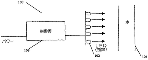
図1は、本発明の一実施形態に従った浄化システムを図示する。LED102は、水を含むチャンバ104を一方の側から照射するよう配置されているが、LED102の配置は多くの異なる形式を取ることができるであろう。例えば、LED102は、チャンバ内に又はチャンバの外に配置され得る。LEDがチャンバの外に配置されるとき、材料は、チャンバの中に組み込まれて、紫外線光の透過を与え得る。この実施形態においては、LED102は、制御器108により制御されている。LED102は、外側の周辺部上に設けられる必要がなく、それらはまた、内側の周辺部上又は水の流れ部又は浴槽の内側に取り付けられることができるであろう。水は、よどんだ、撹拌された、又は混合された浴槽にあることができるであろうし、又は照射プロセスの間流れていることができるであろう。LEDは、水に対して任意の要領で配置されることができ、そして水は、その水が照射される限り任意の要領で提示されることができる。図1はチャンバ104が液体を含むように図示されているが、チャンバはまた、蒸気又は固体を含むように構成されることができるであろう。
【0040】
本発明の別の実施形態は、紫外線写真撮影、検査又は検出のための紫外線LED装置を指向している。
【0041】
一実施形態においては、紫外線放射装置が設けられ、そこにおいて紫外線放射の1次源、2次源、又は唯一の源はLED装置である。この装置は、自立型装置、又は他の装置と組み合わせて、あるいはネットワーク装置であるようネットワークと組み合わされて用いられることができる。ネットワーク構成においては、制御器108は、アドレス可能な制御器であり得る。
【0042】
本発明の原理に従った装置はまた、スチル・フレーム・カメラ、動画カメラ、ビデオ記録装置、又は他の記録装置に組み込まれ得る。写真撮影システムは、フィルムを記録媒体として用いることができ、又はそれらは、画像をディジタルに又は任意の他の手段により格納することができる。
【0043】
一実施形態においては、紫外線放射装置は、検査、照射、又は検出目的のための自立型装置として用いられ得る。この装置は、紫外線照射が希望される任意の目的のため用いられることができる。そのような使用は、材料の検査、身体の分泌物、蛍光表示又は分析、又は医療の理由を含むが、これらに限定されるものではない。装置はまは、紫外線光を像形成又は制御のため用いる製造ライン及びプロセス制御のような他のシステムに組み込まれることができる。
【0044】
一実施形態においては、装置は、異なる出力スペクトルを有する1つ又はそれより多いLEDを用いて構成されて、所望の放射出力を与え得る。異なる波長特性を有する幾つかの異なるLEDはまた、様々な応用に対して用いられることができるであろう。異なる波長のLEDを用いる一例は、1個の紫外線放射型のLEDが異なる紫外線波長の別の紫外線放射LEDと組み合わされる場合、又は可視又は赤外線(IR)LEDがシステムの中に組み合わされる場合である。可視LEDは、効果を狙って、又は撮影されるべき被写体又は対象物に放射を向けるのにユーザを支援するため組み合わされ得る。出力レベルは、一旦照明方向及びパターンが設定されると調整されることができる。装置の紫外線対可視対IRの比放出特性はまた、特定の応用に適合されるよう変えられることができるであろう。
【0045】
紫外線光又はディープ青色光を用いて照射されたとき蛍光発光する入手可能な多くの材料がある。本発明の一実施形態においては、これらの材料のいずれかが、LED光と組み合わせて標識及び表示に用いられて、独特の視覚的効果を生成することができる。材料は、コア、ロッド、チューブ及びシートのようなプラスチック材;蛍光塗料、燐光塗料、及び紫外線又は青色照射の下で現れる非可視塗料のような塗料及び染料;水溶性染料(water dyes);泡状流体;及び反射し、蛍光発光し、又は燐光発光する任意の他の材料を含むが、これらに限定されるものではない。これらの材料をLED照明と用いることができる応用は、表示、マークの識別、背景幕、舞台芸術、ボディ・ペイント、刺青、クラブ・ウエア、パーティ製品、バー製品、配膳業製作物、3Dグラス(3D glasses)、フロア・タイル、映画、フィルム、テレビジョン、劇場、コンサート、イベント、会議、報道機関台(press launches)における特別な効果を含むが、それらに限定されるものではない。他の応用は、クラブ、パブ、バー、映画館、カジノ、ホテル、テーマ・パーク、娯楽パーク・アトラクション、ボーリング・レーン、クエーサ・アレーナ(quasar arenas)、ゲームセンタ、及び任意の他の範囲における舞台(風景)効果のためこれらの材料及びLED照明を用いることを含むが、それらに限定されるものではない。他の応用は、販売地点で、ウィンドウ陳列、標識、広告板、展示スタンド、及び製品台(product launches)及び任意の他の表示における販売促進及び宣伝広告を含むが、それらに限定されるものではない。
【0046】
図2は、浄化、検査、紫外線写真撮影又は他の使用のため本発明の一実施形態に従って自立型LED装置200を示す。この実施形態における装置200は、1つ又はそれより多いLED102及び手持形ハウジング202を含み得る。図2に示されるように、装置は、異なるスペクトル出力を有する2以上のLEDを含み得る。図3は、2つのLEDユニットを含み、その1つはカメラ302の前に組み合わされ、そしてもう1つはカメラの頂部に着脱可能なユニットとして配置されている別の実施形態を示す。
【0047】
それらLEDは、制御信号を印加すると殆ど瞬時に光を生成し、そしてこれは、それらをフラッシング又は脈動モードに適するようにして、異なる効果又は電源の節約を生じる。装置は、被写体が回転され又は移動される間に周期的に脈動するよう設定されることができるであろうし、又はパルスは、非常に通常のカメラ・フラッシュのように印加されることができるであろうし、そこにおいて印加又は放射は、シャッターが開く瞬間にのみ生じる。
【0048】
前述のように、本発明の実施形態に従った装置におけるLEDは、受動又は能動回路により制御されることができる。マイクロプロセッサを用いて、制御信号をLED、又はLEDのネットワークに与えることができるであろう。マイクロプロセッサはまた、プログラミング装置からの入力信号を有することができるであろう。プログラミング装置は、例えば別の装置からの入力信号を受信するため受信器を含むことができる。入力信号は、カメラから到来し、又はトランスデューサ、スイッチ、送信器又は信号を供給するための他の装置に限定されるものではないが、これらのような他の装置から到来することができるであろう。信号は、ディジタルに、又はA/D変換器を介したアナログ信号として受信されることができるであろう。制御器はまた、送信器又は他の出力装置に接続されて、他の装置との通信を与えることができる。LEDはまた、紫外線LED、可視LED、IRのLEDのいずれを用いるにせよ、通信デバイスとして動作することができる。PWM制御信号は、同じ又は別個のLED上に通信出力を作る間に光制御出力を変調することができる。LEDは、駆動信号に非常に迅速に応答するので、1つのLEDが、通信と照明の両方を同時に与えることができる。別個のLEDをまた用いて、通信を与えることができる。
【0049】
本明細書に援用されている米国特許No.6,016,038に定義されているように、パルス幅被変調(PWM)制御信号を用いて、LEDを駆動することができるであろうし、そこにおいて該制御信号は、動作のモードを変えるための入力信号に対応する。この技術を用いて、変調し、従っていずれのLEDの出力を調整することができるであろう。紫外線と可視とIRとの組み合わせを変えて、大きな範囲の効果を得ることができる。
【0050】
一実施形態においては、可視LEDが装置に用いられる。可視光生成LEDを、例えば、照射方向及び/又は強度のための基準として用い得る。一般的に、紫外線写真撮影技術は、所与のセッティング及び対象物に対して適切な露出時間を決定するため試行錯誤を要求する。紫外線メータをまた上記装置と用いることができるが、しかし可視光写真撮影におけるように紫外線写真撮影に対して決定された良好な相関係数がない。しかしながら、紫外線メータは、この装置と組み合わされてフィードバックを与えることができるであろう。フィードバックのための別の方法は、LEDパワー・メータ又は制御信号インディケータを介してであろう。可視LEDをまた用いて、どのくらいの紫外線放射があるかを参照することができるであろう。紫外線放射はユーザにとって見ることができないので、ユーザは、光強度に関してのフィードバックを持たない。理論的に決定されるにしろ、経験的に決定されるにしろ、相関は、可視LEDからの可視光強度と紫外線LEDのそれとの間に引かれることができるであろう。これは、ユーザが可視光の強度を調整して紫外線を設定し次いで可視光LEDをターン・オフし又はそれらの入力を低減するのを可能にするであろう。これは、ある効果を作るため要求された強度を設定し又は調整するのにユーザにとって有効であることができるであろう。
【0051】
マイクロプロセッサは、可視光強度を紫外線光強度と等しくするルックアップ・テーブル又は関数を有することができるであろう。また、このルックアップ・テーブル又は関数は、カスタマイズされた較正解を与えるためユーザが調整可能であることができるであろう。
【0052】
本発明の原理に従った装置はまた、写真撮影なしで対象物を視認及び検査のため用いられることができる。一実施形態においては、装置は、検査プロセスを支援するため検査光学部品を組み込んで提示される。光学部品は、拡大鏡又は顕微鏡のような任意の光学部品を含むことができるであろうが、これらに限定されるものではない。そのような装置は、様々な形式を取り、携帯型又は非携帯型であることができるであろう。この種類の装置はまた、検査のための他のシステムに組み込まれることができるであろう。装置は、視覚システムの中に組み込まれることができるであろうし、そこにおいて検査範囲内の対象物は、紫外線下でより良好に規定される。
【0053】
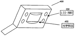
図4は、拡大鏡402及びLED102を備え、本発明の一実施形態に従った紫外線検査装置400を図示する。図5は、本発明に従った懐中電灯型紫外線源を図示する。
【0054】
検査及び写真撮影の応用の一部は、石の検査用器具のような岩片質のソーシング(lithic sourcing)、貨幣の識別、スタンプ及び染料の識別、修理された物品、グルー、接着剤、エポキシ、油、グリスの検査、動物の排出物が蛍光発光する形跡を残すげっし類動物の制御と共に、医療検査、研究所試験、蛍光液体浸透剤検出(fluorescent liquid penetrent detection)、放火検出、紫外線スプレーの識別、指紋識別、及び紫外線の助けによって検査し且つ写真撮影するのに有用である他の表面又は物品を含むが、しかしこれらに限定されるものではない。
【0055】
本明細書に説明されるような装置はまた、インク、セメント、エポキシ、又は紫外線放射の下で養生することができる任意の他の材料のための養生システムとして用いられ得る。装置はまた、ブラック・ライト、日焼け、EPROM消去、ウェブ・プリンティング、空気浄化、又は材料の滅菌のため用いられることができる。LED駆動された紫外線源を用いる養生装置、検査装置又は他の装置はまた、紫外線通過ファイバ光学部品と結合されて、局所的又は分散した紫外線放射を遠隔範囲に与えることができる。ファイバ光学部品からの出力は、光の更に分配のため他の光学部品に接続されることができる。
【0056】
局所的日焼け、又はパターンを皮膚上に日焼けさせることはまた、本発明の原理に従ったシステムを用いることにより達成され得る。LED光源は、単一のLEDが皮膚上をゆっくり移動して、局所的日焼けを与えることができる程コンパクトである。同様に、1群のLEDは、パターンになるよう形成され、そしてパターンを用いて皮膚を照射するため用いられることができるであろう。LEDのビーム角度を変えることにより、パターンの大きさ及び定義を変えることができるであろう。1群のLEDはまた、光学部品を有する照明器具の中に組み立てられて、焦点合わせ又は光のパターンを与えて、日焼けパターンを生成することができるであろう。光学部品はまた、遠隔アクセスを与えるためのファイバ光学部品を含むことができるであろう。LED装置は、衣服に組み込まれて、衣服を着ている間に照射を与えることができるであろう。
【0057】
殺菌効果のための紫外線照射の1つの特別の実効的応用は、空気処理システムにおける微生物成長の制御にあった。レジオネラ症は、建物の空気処理システム又は戸外空気取り入れ口近くに見つけられるバクテリア又は菌類により発生する場合がある。特に、冷却コイル及びフィルタ組立体の紫外線への一定の暴露は、菌類の成長の制御で非常に効果的であることが分かった。ウイルスは、特に紫外線に対して抵抗力が無く、バクテリアより非常に紫外線に対して抵抗力が無い。ウイルスは、水銀放出の254nmより上の波長に一層敏感である。空中生物工学紫外線殺菌照射(Aerobiological Engineering Ultraviolet Germicidal Irradiation)、 HYPERLINK ”http://www.engr.psu.edu/ae/wjk/wjkuvgi.html” www.engr.psu.edu/ae/wjk/wjkuvgi.htmlを参照のこと。一実施形態において、UV LED装置は、空気処理システム内のエア・チャンバ及び/又は濾過システムを照射して、空気及び/又は空気処理及び/又は濾過システムを浄化するよう配置され得る。
【0058】
一実施形態においては、LED照明器具は、自動車のダッシュボード照明、ミラー照明、又は自動車内外の任意の他の範囲に、又は他の標識及び表示応用のため組み込まれることができる。照明パイピング又はエッジ照明は、三価のリンを含む材料又は発光材料と組み合わされることができ、それによりそれらは、LEDが付勢されたとき蛍光発光する。発光材料は、表面照明を与えるための層として塗布されることができるであろうし、又はそれは、あるパターンで塗布されることができるであろう。
【0059】
植物は成長するため光を必要とし、そして日光の欠乏している場所で植物を照射するよう設計されている多くの人工的光源がある。これらのシステムは、HID、蛍光性光源、及び白熱光源を用いて、必要な光を与える。赤色LEDのみ、又は植物の生長に幾らかの積極的な効果を示す蛍光照明と組み合わせて用いる効果の研究があった。植物の生長のための発光ダイオード(Light−Emitting Diodes for Plant Growth)(W.M.Knott,Ph.D.及びR.M.Wheeler,Ph.D.、MD−RES)http://technology.ksc.nasa.gov/WWWaccess/techreports/94report/lsf/ls04.htmlを参照のこと。また、異なる波長の様々な比が植物の生長の挙動に及ぼす影響を示す研究があった。様々な放射源の植物生長への影響(Effects of Various Radiant Sources on Plant Growth)(Shinji TAZAWA、光源部門、岩崎電気株式会社(Iwasaki Electric Co. Ltd.) HYPERLINK ”http://ss.jicras.affic.go.jp/engpage/jarq/33−3/tazawa2/tazawa2.htm” http://ss.jicras.affic.go.jp/engpage/jarq/33−3/tazawa2/tazawa2.htm、及び植物の生長及び開発(Plant Growth and Development)(USDA NRICGP 資金提供された研究の要約(Abstracts of Funded Research)、FY 1997年)http://www.reeusda.gov/crgam/nri/pubs/archive/abstracts/abstract97/plgrwdev.htmを参照のこと。また、照明サイクルの中断及びその開花への影響の研究があった。植物生長に影響を与える要因のレビュー(A Review of Factors Affecting Plant Growth)(Marianne Ames(卒業フェロー)、Wayne S.Johnson(助教授)ネバダ大学(Reno))http:www.hydrofahm.com/content/articles/factors_plant.htmlを参照のこと。照明を用いて、植物の生長を遅らせる又は増大させることができる。
【0060】
本発明に従ったシステム及び方法はまた、植物の生長の制御のため用いられ得る。この種類の照明システムは、植物生長の抑制手段又は植物生長支援手段として屋内又は屋外で用いられることができるであろう。LED装置は、1個の波長LED、又は紫外線、可視光又はIRをカバーする幾つかの波長LEDを用いて構成されることができる。この開示において説明される制御技術を用いることにより、光の比を容易に生成し、そして特定の使用のためカスタマイズされることができるであろう。例えば、所望の出力がより高い青色対緑色比を要求する場合、青色LEDの強度は、増大されることができるであろうし、及び/又は緑色LEDの強度は減少されることができるであろう。この種類のスペクトル操作は、このLEDシステムを用いて制御されることができるであろう。照明をまたプログラムして、LED出力を時間又は他の入力の関数として変えることができるであろう。例えば、光電セルをプログラミング・デバイスとして用いる場合、照明装置は、その出力全体を増大して、所与の時間における日光の欠乏を補償することができるであろう。LEDベースの装置は、植物が1日の特定の時間により多くの紫外線、又はより多くのIR、又は光の特定の比を、又は1日を通して循環されることを要求するならばその出力を調整するよう設計されることができるであろう。これらの動的な色及び放射変化効果は、植物生長の増強又は植物生長の低減のための多くの機会が生じることを可能にする。
【0061】
一実施形態においては、照明装置は、日光が最小であり又は入手可能でない範囲で通常の外部照明条件をシミュレートするようプログラムされ得る。そのシミュレーションはまた、成長を増強又は低減するよう調整されることができるであろう。例えば、システムからのスペクトルは、変調され得て及び/又はサイクルの調時が変えられ得る。一実施形態においては、プログラムは、昼光のサイクルを24時間の期間にわたりシミュレートするよう設計され得て、そしてそのプログラムは、そのサイクルを加速するよう修正され得て、それにより或る程度シミュレートされたサイクルが24時間の期間に実行される。例えば、1日のシミュレーションを24時間期間内で複数回循環させることにより、植物の生長が増強され得る。
【0062】
また、本発明に従ったシステム及び方法を用いて、一般的照明、セラピー、治療、特別の照明条件、日焼け、又は全スペクトル又は選択的なスペクトル照明を希望する又は必要とする任意の他の照明状況のため全スペクトル又は部分スペクトル照明を提供し得る。これらの装置は、特別の用途又は一般的用途のため作り又は設計することができる。一般的用途のため作られた装置はまた、その装置を特定の要望に対して調製するため調整可能であることができる。LED装置は、幾つかの異なる波長生成LED又は1つの特定の波長又は波長領域を用いて作ることができるであろう。紫外線、可視又はIR生成LEDを採用することができるであろうし、そしてこれらのスペクトル領域のそれぞれからの幾つかのLEDを採用することができるであろう。スペクトル領域内の選択された波長又はスペクトル領域又は波長のそれぞれは、極めて多くの特定のLED、又は所望の領域内のより大きい強度のLEDを用いることにより、又は全て又は一部のLEDを制御して可変出力制御を与えることにより、強度を変えることができるであろう。
【0063】
一実施形態においては、多くのUV放出LED照明装置又は単一の装置を、オフィス又は部屋又は屋外で全又は部分スペクトル照明並びにある範囲又は対象物の一般的照明を与える一般的目的のため用い得る。装置をまた、治療又は医療技術と一緒に治療又は医療の環境で用いることができるであろう。ディープ紫外線波長が希望されそして含められ又は強度が増大されることができるであろう応用もある。
【0064】
一実施形態においては、応用は、オフィス環境の照明及び光の色温度、並びに1日の時間に対応する屋外条件をシミュレートするため放出変化の紫外線及び赤外線成分のため用いられるLED装置を含み得る。これをまた用いて、人々が夜間に働いているときのような1日の不適切な時間を人工的にシミュレートすることができるであろうし、そして人々は、昼光照明条件に仕事時間中にさらされて、かれらの内部時計をかれらの仕事時間と同期状態に保つことができるであろう。早朝時間は、低い色温度を持つ比較的低い紫外線成分を有することができるであろうし、そして真昼光レベルの間の或る赤外線光は、高いレベルの紫外線を持つ一層高い色温度を有するであろう。紫外線又はいずれの他の波長は、問題を避けるため選択的に排除されることができる。例えば、紫外線スペクトルは、3つのカテゴリ、即ちUVA、UVB及びUVCに分類される。UVB及びUVCは、しばしば複数の比較的短い暴露時間内に皮膚及び眼の炎症を起こすことと関連され、そこで、これらの波長は、過剰暴露を防止するため出力で排除又は低減されることができるであろう。
【0065】
本発明の原理に従ったLED装置はまた、それがどの波長を放出し、そしてそれがどの程度の強度で放出するかの点で非常に融通性があることができるであろう。各エネルギ領域が選択可能で且つ調整可能あって、ユーザが特定の用途に適するよう必要な又は所望の調整をするのを可能にすることができるであろう。装置はまた、任意のサイクルを通過するようプログラムされることができる。医者は、15分間の明るい光の治療を処方し得て、そこにおいて可視光強度は高いが、しかし紫外線光強度は低く、これに低い可視エネルギであるがしかしより高い紫外線又はIRの10分の期間が続く。装置はまた、スイッチ、単一のスイッチ、トランスデューサ、受信器、検出器、又は入力信号を与えるための任意の他のデバイスを通して調整されることができるであろう。
【0066】
全スペクトル又は部分スペクトルLED装置をまた製品試験のため用いることができるであろう。多くの製品は、それらが様々な照明条件にさらされる屋外で用いられよう設計されている。試験条件は、多くの場合研究所で再現するのが難しく、そして特定の照明条件は、再現が困難である効果の一部である。例えば、試験は、LED装置を用いてネバダの夏の日をシミュレートすることを案出されることができるであろうし、そして製品は、そのシミュレートされた光の下で試験されることができるであろう。LED装置を他の試験構成要素と一緒に用いて、様々な条件を生成することができるであろう。例えば、照明装置は、オーブンと組み合わされて、ネバダの夏の日の熱及び照明効果をシミュレートすることができるであろう。一旦これらの条件がシミュレートされると、ユーザは、製品を、試験を加速する方法として連続的又は変化する条件を受けさせることができる。
【0067】
これらのLED装置をまた用いて、物理的病気を治療又は防止することができる。乾癬及び黄疸は、通常紫外線光の付与により治療される2つの医療状態である。紫外線源をまた用いて、病気、及びHIVを含む他の血液で運ばれたウイルスの治療のため血液を照射する。LED装置はまた、同定又は治療のため医療環境において組織又は器官を照射するため用いられることができる。
【0068】
一実施形態においては、発光ダイオード・ベースの紫外線光源は、車両の前に配置されることができるであろう。これは、道路表面上でラインを照明するのに有効であることができるであろう。高速道路のラインは、例えば、通常白色のラインであり、そして紫外線光で照射された場合蛍光発光するであろう。ペイントはまた、蛍光発光効果を最適化又は増大させるため増強されることができるであろう。この種類の照明を与えることにより、道路上のラインは、ハロゲン・ランプでもって照明された同じ道路と比較して非常にはっきりと分かるようになるであろう。車両は、自動車、カー、電動式車両、非電動式車両、自転車、オートバイ、原付自転車、トラック、バギー、又はバスのような任意の種類の車両であってよいが、これらに限定されるものではない。光学部品をまた用いて、光を設定された距離に焦点合わせすることができる。これを用いて、道路のライン上に高強度の光を与えることができるであろう。ビームは、一点に焦点合わせされ、又はある範囲に広げられることができるであろう。
【0069】
LED光源は、紫外線のような単一の色のLEDを装備していることができるであろうし、又はその光源は、幾つかの色の組み合わせを持つことができるであろう。青色及び紫外線の組み合わせは、光がオンであることのインディケータを与えるのに適切であり得る。青色発光体は、光が付勢されたことを示すであろう一方、紫外線発光体は、道路を照明して蛍光発光効果を起こすであろう。異なる波長発光体の任意の組み合わせを用いることができるであろう。従来から、黄色駆動光は、車の前にフォグ・ライトとして用いられてきた。それは、より長い波長の黄色光は、著しく青色の成分を生成する光より霧の中で散乱が少ないからである。黄色光を用いる他の理由は、眼の明所視の感度曲線の中心に近く、そこで黄色光がより効率的であることである。この発明を用いて、紫外線発光体は、黄色発光体と組み合わされて、可視性及び蛍光発光効果を与えることができるであろう。単一色の黄色、白色、又は他の色はまた、車両で所望の照明を与えるため用いられ得る。
【0070】
紫外線LEDを自動車の前部上に2次照明源として用いる利点は、紫外線が他の車両又は歩行者から離れて道路上のラインに向けて指向されることができることである。これは、紫外線放射をそのような目標に直接指向させることと関連したいずれの問題を軽減するのを助けることができる。この装置は、自動車上での紫外線発生の代案と比較して比較的単純であろう。唯一の他の現実的な代案は放電光源である。これらの光源は適切な動作のため高コストの電子機器を用い、そしてそれらは一般的に広帯域発光体である。LED装置を用いた場合、用いられる別々の色はまた、個々に制御されて、装置の放射出力を変えることができるであろう。これは、ある一定の駆動条件のため、特定の視覚障害を持つ人々への補助として、又は車の装飾用構成要素として有効であり得る。光がまた、車をより魅力的にするため、減光され、そして色同調されることができるであろう。別の実施形態においては、UV発光体は、一旦車両が所定の速度に達したときのみ付勢され得る。
【0071】
自動車上のLED照明装置はまた、通信装置として用いられることができるであろう。LEDは、電力の印加に殆ど瞬時に応答し、そして優秀な通信装置として使用できる。IR LEDは、典型的にはこれらの特性のため遠隔制御装置に用いられる。LED装置はまた、料金所、ガソリン・スタンド、サービス・ステーション、コンビニエンス・ストア、又は自動車の識別又は他の用途における他の発生地において用いられることができるであろう。
【0072】
本発明に従った紫外線LEDシステムはまた、低温殺菌のため用いられることができる。一般に、熱プロセスを用いて、低温殺菌を達成するため用いられるが、しかし熱プロセス装置は、大きくそして購入するには高価である。小さいビジネス又は限定した生産をしている多くの果汁生産者及びミルク生産者がいる。これらの経営者は、より小さく、より低コスト且つ動作させ易いようにすることができるであろうLED装置を用いることにより利益を得ることができるであろう。紫外線放射は、果汁及びシードルの中のバクテリア大腸菌(bacteria E.coli)を低減し又は殆ど排除するための効率的な方法であることが分かった。 HYPERLINK ”http://www.sciencedaily.com/reasonses/1998/01/980127065910.htm” www.sciencedaily.com/reasonses/1998/01/980127065910.htm「紫外線光による低温殺菌が、新鮮なシードル及び果汁のバクテリア汚染をなくすことができるであろう(Pasteurized via Ultraviolet Light Could Zap Bacterial Contamination of Fresh Cider and Fruit Juices)」を参照のこと。
【0073】
この種類の紫外線照射装置が殺菌装置として有効であろう応用は、飲み水、廃水、飲料水、温泉水、冷却タワー、水栽培、滝及び噴水、スイミング・プール、水治療法、プール、温泉、病院及び研究所の水、製薬、事前逆浸透(pre reverse osmosis)水殺菌、食料及び飲料処理、水槽及び魚養殖場、かきの浄化、任意の光学的透明液体、ホワイト・ビネガー、リンゴ・シードル、有機切削油、温水ループ、養魚、農業、及びアクアリウムを含むが、これらに限定されるものではない。製薬プロセスにおける別の利用は、錠剤上の錠皮を硬化することである。
【0074】
紫外線光はまた、研究所で、キレート剤の結合を切る方法として用いられる。この反応を促進するため、本発明に従ったLED紫外線装置を設けることができる。その装置は、図6に示されるように、かき混ぜ棒に非常に似ているものであることができるであろうし、その図6においては、少なくとも1つの紫外線生成LED102は、液体に浸されたかき混ぜ棒の端部に含まれていることができるであろう。この種類の紫外線装置はまた、液体の個々の容器の浄化のため用いられることができる。紫外線放射を増大するため、又は色を液体又は容器に加えるため、幾つかのLEDを含めることができるであろう。一実施形態においては、UV装置は、角氷の形状であり、又は形状が角氷のハウジングを持ち得る。本明細書に記載された全ての他の装置の場合のように、LEDは、プロセッサからの制御信号を用いて駆動されることができ、又はLEDは、受動回路を用いて駆動されることができる。LED回路は、LEDを単純にターン・オン及びオフすることができ、又は異なるLEDのパワー調整を採用することができるであろう。調整が希望される場合、それは、受動回路を通して達成される、又はパルス幅変調電流制御又は任意の他の制御方法を通して制御されることができる。
【0075】
LED装置に対する別の応用は分光光度計にある。分光光度計は、物質の透過及び吸収特性を決定するため用いられる分析的ツールである。典型的な分光光度計は、200から800nmのスペクトルを生成するであろうが、とはいえ異なる範囲も使用可能である。200から800nmの範囲を有する分光光度計は、US/VIS分光光度計と呼ばれる。IR装置もある。これらの装置は、単一の光源又は幾つかの光源を有して、物質を所望の範囲の波長で放射し得る。要求される放射の全部又は一部を供給するため、LED光源を設けることができるであろう。LED光源は、紫外線及び赤外線を含む広いスペクトル範囲をカバーするLEDのアレイを含むことができるであろう。様々な波長のLEDは、独立に制御されて、特定の波長を試験手順の間に与えることができるであろう。この方法は、装置内の干渉量を低減し、その結果として測定エラーを低減することができる。
【0076】
本発明の原理に従った紫外線又は青色LED装置を、捕らえる又は電気で殺すため昆虫を引きつけるための虫用照明として用い得る。昆虫制御装置は、典型的には蛍光ランプを用いて構成され、そして一部の応用では炭酸ガス放出器も用い得る。昆虫は、青色及び紫外線光に感じやすい明所視応答曲線を有する。それらはまた、炭酸ガスに引きつけられる。その結果、今日主に用いられている2種類の殺虫装置、即ち、青色蛍光ランプ又はブラック蛍光ランプ(black fluorescent lamp)及び炭酸ガス装置がある。これらの装置は、昆虫を引きつけ、次いでそれらを電気により又は物理的に捕まえることにより殺すよう設計されている。蛍光ランプは、LEDデバイスと置換されることができ、そして特定の昆虫の明所視応答、又は装置が用いられる物理的環境に対して調製されることができる。LEDは、狭い波長範囲にわたり光を放出するコヒーレント光源であり、そして可視光を与えることなしに紫外線又はディープ青色光を与えるよう配置されることができ、又は可視光が希望される場合、可視LEDを設けることができる。希望するならば、スペクトル放出を広げるため、燐光体をLED又はLEDパッケージに追加し得る。
【0077】
鳥の明所視応答もまた近紫外線領域を含む。紫外線で見る結果、対象物は、鳥に対して極めて異なるように見えてきて、多くの対象物が蛍光発光している。鳥はまた、自身を自由に移動させるのを助けるため紫外線を用いている。鳥はまた、哺乳類及び爬虫類と同様に、ビタミンDを生成するため紫外線光を必要とし、そして紫外線光にさらされない場合、鳥は、様々なカルシウム欠乏症に苦しむであろう。 HYPERLINK ”http://www.users.mis.net/ ̄pthrush/uvmyth.htm” www.users.mis.net/ ̄pthrush/lighting/uvmyth.htmPatiric R.Thrushによる「紫外線の神秘:照明及び適切なダイエット(The Ultraviolet Myth: Lighting and Proper Diet)」(1999年)を参照のこと。本明細書で説明されるようにLED光は、捕らわれ状態にある鳥の健康を助けるため与えられる、並びにそれらがある一定の範囲から出るのを止めるため用いられることができる。
【0078】
全スペクトル照明が鳥の生活を改善するため用いられた多くの例がある。1つのそのような研究は鶏について行われた。過去において、養鶏場は、窓を持ち且つ屋外への経路を持つ小屋で成長させた。現代の鶏小屋は、今では不十分に照明された窓なし建物である。鶏は、それらの産卵量並びに有効卵生産年数により測定されるように屋外の小屋で非常に生産力があった。鶏は、通常、これらの小屋の中で5年間収益性が強く生産的であった。対照的に、新しい窓無し環境で成長した雌鶏は、13ヶ月間継続するのみである。Ott博士により行われた実験は、紫外線を持つ全スペクトル照明を新しい鶏小屋で用いた場合鶏のピーク産出が3年又はそれより長く継続したことを示した。その研究はまた、鳥が5000羽の鶏当たり19,700ドルより少ない飼料を食べ、8.5%より多い卵を産み、2%より少ない卵が壊れ、一方一層大きな卵を産んだことを示した。更に、鳥は、共食いが無かったので、上唇の先端を取り除く必要が無かった。これは、農場主に対して合計91,300ドルより多くの利益を計算した。 HYPERLINK ”http://www.users.mis.net/ ̄pthrush/lighting/ott.htm” www.users.mis.net/ ̄pthrush/lighting/ott.htmJohn N.Ott博士による「平易な常識対科学の理論的不合理性(Plain Common Sense vs. Scientific Theoretical Irrationality)」を参照のこと。それはまた、生物社会的研究の国際ジャーナル(International Journal of Biosocial Research)の特別主題号Volume7(1985年)に掲載されている。
【0079】
Ott博士により行われた実験と似た実験の結果として、我々は、全スペクトル照明が人間にとって健康に良いばかりでなく鳥、爬虫類及び他の動物にとって同様に健康に良いことを知った。LEDを用いて作った全スペクトル又は部分スペクトル光は、これらの応用のため並びに人間の居住地のため与えられることができる。本発明に従った全スペクトル照明装置は、これらの応用のため用いられ得て、そして特定の色上に固定されることができ、又は色が時間又は他のインディケータに関して変わることができる。紫外線又はIRの量は、一日の全体にわたって変わって、自然の照明状態をシミュレートすることができる。
【0080】
本発明の原理に従った紫外線照明システムをまた用いて、鳥がある一定の範囲で生活し且つ食べるのを防止し得る。鳥は一般的に、それらが飛行機の経路に飛び入って航空機に損傷をそして鳥に死を生じさせることができるので、空港の周りで危険であると考えられる。鳥が高速度の航空機にぶつかる衝撃は、500ktsで飛行している航空機が大きな鳥にぶつかる場合その航空機が約207,000キログラム・メートル(1,500,000フート・ポンド)近くのエネルギの衝撃を被ることを考えたとき劇的である。 HYPERLINK ”http://www.tc.gc.ca/aviation/aerodrme/birdskte/info/hazard.htm” http://www.tc.gc.ca/aviation/aerodrme/birdstke/info/hazard.htm「鳥の危険、カナダの輸送(Bird Hazards, Transportation of Canada)」を参照のこと。鳥のぶつかりと関連した問題を軽減するため、調査者は、鳥が航空機から離れている状態を保つ新しい方法を探索した。1つのそのような方法は、鳥が危険である範囲に紫外線光を使用することである。
【0081】
鳥は、紫外線光を見ることができ、そしてそれを視覚及び航行のため用いることができる。紫外線光の抑止効果はものが人工的照射の下で見える方法からであるのか、又はそれがそれらの航行システムと干渉するからであるのか分かっていない。紫外線装置は、空港に地上有効範囲照明としてセットアップされることができるであろうし、又はその照明は、航空機そのもので用いられることができるであろう。その照明は、一定の方向に照射している又は移動可能であるようにできるであろう。ビーコン構成も用いることができるであろう。パルス化又は波長シフト化は、LEDベースの照明装置を用いて容易に達成されることができ、そしてこれは、鳥を阻止する別の方法として働き得る。上記範囲の中の紫外線光のフラッシングは、鳥を悩まし得るが、しかし人間の仕事は、不可視光ショーにより気づれなく又は悩まされないであろう。照明装置はまた、オーディオ装置のような他の装置と用いられて、雑音に照明効果を与えることができるであろう。
【0082】
別の実施形態においては、装置の中のLED(単数又は複数)の出力は、センサ、トランスデューサ、ユーザ・インターフェース又は他の信号発生器から与えられる外部信号のような外部信号を通して制御され得る。信号発生器は、信号を、プロセッサへ、又は外部信号を受け取りそれに応答してLED制御信号を発生及び/又は通信するよう設計された他の回路へ通信し得る。ユーザ・インターフェースは、任意の種類のもの、例えば、ボタン、スイッチ、ダイヤル、又は類似のものであってよく、又はそれは、計算装置を用いて外部信号を発生してLEDの出力を制御するように制御されるソフトウエアであり得る。本発明の原理に従った、外部信号を装置に与えるため用いられる多くのユーザ・インターフェース及び他の信号発生器があることが認められるべきであり、そして、本発明は、いずれの特定の種類のユーザ・インターフェース又は信号発生器との使用に限定されるものではない。
【0083】
本明細書に用いられているように、用語「紫外線」又は「紫外線光」は、紫外線スペクトル、及び可視スペクトルのディープ青領域を含むものである。
【0084】
本明細書に用いられているように、用語「LED」は、全ての種類の発光ダイオード、発光ポリマ、電流に応答して光を生成する半導体ダイ、有機LED、エレクトロルミネセンス・ストリップ、及び他のそのようなシステムを含むと理解されるべきである。「LED」は、個々に制御される複数の半導体ダイを有する単一の発光ダイオードに言及し得る。用語「LED」は、パッケージ・タイプのLEDを制限しないことが理解されるべきである。用語「LED」は、パッケージ化されたLED、非パッケージのLED、表面実装LED、チップ・オン・ボードLED、及び全ての他の形態のLEDを含む。用語「LED」はまた、LEDからのエネルギを異なる波長に変換し得る材料でパッケージされた又はその材料と関連したLEDを含む。
【0085】
本発明は、詳細に示され且つ説明された実施形態に関連して開示されたが、様々な均等物、変更及び改良が当業者に上記の記載から明らかであろう。そのような均等物、変更及び改良は、特許請求の範囲により含まれることを意図されるものである。
【図面の簡単な説明】
【図1】
図1は、本発明の一実施形態に従った浄化装置を図示する。
【図2】
図2は、本発明の別の実施形態に従った検査又は紫外線写真撮影のための自立型LEDを示す。
【図3】
図3は、本発明の別の実施形態に従った2つのLED装置であって、1つはカメラの前に組み合わされ、もう1つはカメラの頂部に着脱可能な装置として配置されているものを示す。
【図4】
図4は、本発明の別の実施形態に従った、拡大鏡を備える紫外線検査装置を図示する。
【図5】
図5は、本発明の更に別の実施形態に従った懐中電灯型紫外線源を図示する。
【図6】
図6は、本発明の別の実施形態に従った紫外線光源を図示する。[0001]
[Related applications]
This application is a provisional application serial number 60 / 235,678 filed on September 27, 2000 "Ultraviolet Light Emitting Device" and a provisional application serial number filed on August 4, 2000. Claims 60 / 222,847 “Ultraviolet Light Emitting Devices” and are incorporated herein by reference.
[0002]
[Background of the invention]
1. Field of Invention
The present invention relates to a light emitting diode device. More particularly, the present invention relates to ultraviolet light emitting diode systems and methods that generate ultraviolet light.
[0003]
2. Explanation of related technology
There are many systems that use ultraviolet light. Some systems are designed to produce effects such as fluorescence effects, while others are used for the purification of objects, liquids and vapors.
[0004]
Water purification systems are in great demand for industrial, household, portable and other uses. These systems are designed to purify a quantity of water before dispensing for consumption or other use. There are many techniques and methods used to purify water. Usually, a wide variety of techniques are used in a single purification device. Filters are generally used to remove particulates from water, whereas ultraviolet light is used to sterilize water. The sterilization process can include passing water through a transparent tube while simultaneously passing ultraviolet light through the tube. Ultraviolet radiation is used to remove most bacteria and viruses.
[0005]
U.S. Pat. 6,080,313, no. 4,876,014, no. 5,024,766, no. 5, 190, 659, No. 5; 5,529,689 and There are many known systems for purifying water, such as the system described in US Pat. No. 5,573,666. All of these systems utilize mercury vapor discharge lamps to generate ultraviolet light. These lamps can be high intensity discharge lamps or more common low pressure mercury discharge lamps such as fluorescent lamps. These lamps are generally selected for their mercury emission emission characteristics. One of the main resonance lines of mercury is at 256 nm of ultraviolet light. The guideline from the EPA, “EPA Guidance Manual Alternative Distincts and Oxidants” (issued in April 1999) for alternative disinfectants and oxidants, has an optimal range of 245 nm and 285 nm for bactericidal effects. It states that it is ultraviolet irradiation during.
[0006]
There are several problems associated with using high intensity discharge (HID) lamps or low pressure discharge lamps for water purification purposes. HID lamps require, for example, a high voltage and high power source to operate the lamp. The ballast for these lamps is large, heavy and not portable. Because of these constraints, HID sources can provide an acceptable solution for the industrial environment, but are not desirable for home or portable devices. A problem associated with fluorescent lamps is that they are fragile because they are relatively long tubes of thin glass. This creates a serious problem for portable devices. This is because many of these portable devices are used during camping or hiking and the portable devices may not be able to handle with the care required to prevent destruction.
[0007]
Another problem associated with using either low-pressure or high-pressure discharge tubes for the production of ultraviolet radiation is that both of these light sources require significant amounts of mercury to produce the desired radiation. It is. Mercury remains a serious environmental and health problem. Many state governments have regulations that apply to the disposal of HID and fluorescent lamps, and these regulations specify that lamps cannot go to normal landfills. These lamps must be handled as hazardous waste or must be properly recycled to prevent mercury from being released. Massachusetts, for example, regulates these lamps under 310 CMR 30.000 “Dangerous Waste Management” and Massachusetts DEP policy “Provisional Guidance for Management of Used Fluorescent Lamps Containing Mercury”. These lamps must be handled as hazardous waste due to their high mercury content.
[0008]
There are many other devices that use discharge lamps to generate ultraviolet light. These devices illuminate equipment designed to cure ink, cement, glue or enamel (such as the materials used by dentists) and other articles with fluorescent properties or other articles with fluorescent properties. Includes equipment designed to inspect. In some applications, a fluorescent dye is applied to the article and an ultraviolet light source is used to check for the presence of the dye.
[0009]
Ultraviolet photography is used for many applications and provides information that is otherwise difficult to depict. There are two main ways to photograph an object under ultraviolet light: reflection photography and fluorescence photography. There are many applications for UV photography ranging from recreational, scientific and medical to geology. Using ultraviolet light, the object can be illuminated for inspection as well as photography illumination, and the appearance of the object can be verified under ultraviolet irradiation.
[0010]
Most ultraviolet photography is performed by irradiating a photographic sample with a long wavelength of 320 to 400 nm of ultraviolet light. Long wavelength UV radiation is often preferred because many conventional camera lenses pass long UV wavelengths. Shorter wavelength UV light can be used, but special UV transmissive glass must be used for the lens to allow the reflected UV light to reach the film. Another problem associated with shorter wavelengths of ultraviolet radiation is eye and skin hazard. Special precautions must be used when using shorter wavelengths, even though longer wavelength UV radiation may also cause concern for eyes and skin tissue if there is an extended period of exposure. With proper alignment between the emitted ultraviolet light and the lenses that pass these wavelengths, proper selection of the film is important. Most black and white films are sensitive to ultraviolet light, so this is not a problem.
[0011]
The difference between reflection photography and fluorescence photography is the method used to illuminate the object to be photographed. Usually, a fluorescent lamp with a special UV-generating phosphor is used to illuminate the object. These lamps emit radiation other than the ultraviolet radiation itself, and this radiation can be present in the visible spectrum. If visible radiation is not filtered out, the film responds to visible light and the desired effect may not be achieved. In reflective photography, a filter is placed in front of the camera lens to filter out all visible energy while passing ultraviolet light. In fluorescent photography, a UV pass filter is placed in front of the UV light source to eliminate all visible energy, and another UV pass filter is placed in front of the camera lens to remove stray light. This technique offers different effects and is useful for several applications including but not limited to archeological photography. See "Ultra Violet Photography" by Eliadis Elias.
[0012]
Ultraviolet photography can be applied to fingerprints and images of body secretions from animals and humans, images of articles that have fluorescent materials applied or fluorescent, medical images, natural objects, arts, articles. It can be used in many applications such as, but not limited to, capturing repairs, traces or residues made to them. When objects are illuminated with ultraviolet light, they appear quite different from when illuminated with visible light. Geologists use ultraviolet light to inspect the stones to identify stone components and materials or levels of water penetration. A UV light source is required for inspection of these various items, and UV imaging is required to capture the image.
[0013]
Another example of UV inspection or photography is in the analysis of insect life patterns. Insects can only see ultraviolet light and short visible light, where the best way to see what they see is to illuminate the object with the same light. The best way to capture these images after irradiation is to use ultraviolet photography. Many photographers also use UV photography techniques for artistic reasons to capture unique images that cannot be achieved with any other technique.
[0014]
Another area where ultraviolet light is used is phototherapy. Phototherapy can take many forms and can be designed to treat mental, emotional, or physical illness or disease. Full spectrum illumination or specific wavelengths of visible, ultraviolet or infrared radiation can be used during the treatment of such diseases or disorders. Phototherapy has been a highly regarded medical technology throughout history. The sun is a good light source for full spectrum illumination and can provide a therapeutic effect. Many phototherapy techniques attempt to provide light that mimics sunlight.
[0015]
Several recent studies suggest that it is important to be exposed to full spectrum illumination. According to photobiologist John Nash Ott (honor) Dr. Sc. (Hon.), Poor lighting is a serious threat to health. Most artificial such as incandescent bulbs and fluorescent lamps The lighting system lacks a perfect balance of the emitted wavelengths to be classified as full-spectrum light: when 90% of an individual's day is spent under these types of light sources, This can lead to a number of problems ranging from fatigue to loss of function to physical illness.The US Navy has recently responded to the effects of personal occupation and the growth of melanoma. A study of occupational effects has been completed, which suggests a counter-intuitive correlation between occupation and melanoma, while occupations requiring almost exclusively indoor activity show the highest incidence of cancer, while Need outdoor exposure Occupation brought the lowest growth of. This study suggests that may be differentially or prevented treated by cancer some form is exposed to full spectrum lighting.
One embodiment of the present invention is directed to an improved system and method for providing ultraviolet light.
[0016]
[Summary of Invention]
The present invention relates to an ultraviolet system and a method for producing such a system comprising a light emitting diode.
[0017]
One embodiment of the present invention is a purification device. The purification device comprises a purification chamber and at least one LED that generates ultraviolet light, the at least one LED being arranged to illuminate the interior of the purification chamber.
[0018]
Another embodiment of the invention is a handheld device. The handheld device comprises a handheld housing and at least one LED that generates ultraviolet light, the at least one LED being arranged to irradiate from the handheld housing.
[0019]
Yet another embodiment of the present invention is an insect illuminator. The insect illuminator may comprise at least one of an ultraviolet light generating LED and a blue light generating LED to attract insects and at least one of an insect trap and an insecticidal device.
[0020]
Another embodiment of the invention is a method of purification. The cleaning method includes providing at least one LED that generates ultraviolet light, providing a chamber for containing at least one of liquid and vapor, and using the at least one LED to Irradiating the interior.
[0021]
Yet another embodiment of the present invention is a method of cleaning a surface. A method of cleaning the surface includes providing a hand-held housing and providing at least one LED that generates ultraviolet light, the at least one UV LED being associated with the housing and from the housing. Providing the at least one LED arranged to illuminate and allowing the user to hold the housing and illuminate the surface to be cleaned.
[0022]
Yet another embodiment of the present invention is a method of irradiating an object using ultraviolet light. The method of irradiating an object using ultraviolet light includes providing a handheld housing and providing at least one LED that generates ultraviolet light, wherein the at least one LED is associated with the housing. And providing the at least one LED arranged to irradiate from the housing and allowing the user to hold the housing and irradiate the object.
[0023]
Another embodiment of the invention is directed to a lighting device. The lighting device includes at least one visible LED that generates visible light, at least one ultraviolet light LED that generates ultraviolet light, and a processor that independently controls the at least one visible LED and the at least one ultraviolet light LED. And a housing, wherein the LED is housed and arranged to irradiate from the housing.
[0024]
Another embodiment of the invention is directed to a method of illuminating a display. The method of irradiating the display may include providing a display, providing a plurality of ultraviolet LEDs, and irradiating the display using the ultraviolet LEDs.
[0025]
Another embodiment of the invention is directed to a method of affecting plant growth. The method of influencing the growth of the plant comprises providing at least one ultraviolet LED, providing at least one visible LED, and a processor that independently controls the at least one ultraviolet LED and the at least one visible LED. , Directing the at least one ultraviolet LED and the at least one visible LED to illuminate a plant, and causing the processor to vary the output of the LED over time.
[0026]
The following drawings illustrate certain illustrative embodiments of the invention, where like reference numbers indicate like components. These illustrated embodiments are to be understood as illustrative of the invention and are not to be understood as limiting in any way.
[0027]
[Detailed Description of Preferred Embodiments]
The following description relates to some exemplary embodiments of the invention. Many variations of the invention can be envisaged by those skilled in the art. Such variations and modifications are intended to be within the scope of this disclosure. Accordingly, the scope of the invention should not be limited in any way by the following disclosure.
[0028]
One embodiment of the present invention is directed to the use of light emitting diodes that generate ultraviolet radiation for cleaning, inspection and many other uses. This includes numerous advantages over conventional UV light sources, including that it is mercury free.
[0029]
The advent of high brightness light emitting diodes (LEDs) has opened many new applications for LEDs. LEDs are mainly used as indicator light and are now being used as lighting devices. The brightness of LEDs has increased exponentially over the past 30 years. The LED is now described in US Pat. It is being used in color change lighting devices such as those described in US Pat. LED manufacturers such as Nicha, Lumileds, Philips, Siemens, and Osram Opto are all trying to produce LEDs that produce high-efficiency, high-quality white light. This is for general lighting applications to replace incandescent, halogen, and fluorescent lighting.
[0030]
White LEDs are typically devices that produce blue, violet, or ultraviolet light that is converted to visible radiation through a phosphor. If the phosphor layer is removed, the LED becomes a source of ultraviolet radiation. Nichia also recently announced a purple LED with a main emission spectrum having a wavelength between 395 nm and 420 nm. This short wavelength may be acceptable for water purification purposes. If even shorter wavelengths are desired, U.S. Pat. 6,084,250 discloses an LED having an emission centered between 300 nm and 370 nm. Other UV-generating LEDs are available or can be manufactured to generate radiation in different UV bands. Recent trends in the development of UV LEDs indicate that light emitting diodes that produce even shorter wavelengths are soon available. A die could also be developed to generate deep ultraviolet for the production of ozone to assist in the water purification process. Ozone treatment is typically a separate process from ultraviolet treatment.
[0031]
The UV-generating LED can be used to purify water in a manner similar to the mercury-containing discharge tube method. The purification system can include one or more LEDs and provide an essential level of ultraviolet radiation. This new method of water purification should be provided as a stand alone device or in combination with other purification devices such as, but not limited to, filters, scrubbers, other UV light sources, mixers and any supply system Can do.
[0032]
UV-generating LED devices are also used to kill bacteria and viruses, or on surfaces, tables, worktops, walls, floors, ceilings, utensils, tools, household items, storage devices, food processing equipment, food, drinks or any other It can be provided for general sterilization in non-water applications such as for the treatment of surfaces, devices that can be sterilized or objects. One example of using the device in non-water applications is when a kitchen worktop requires disinfection. The hand-held LED device can be used by moving the hand-held LED device on the counter in the same way as using a sponge. The device could also be designed to automatically cover or traverse the entire countertop. Another application would be when the device is combined with a medical instrument drawer. The device could be arranged to illuminate the inside of the drawer to provide a sterile instrument. The device can also be used in connection with other sterilization procedures, or the other sterilization procedures follow. One significant problem with sterilization is keeping the object sterile after the sterilization process is complete. Thus, in the example of a medical device, the device could be exposed to ultraviolet radiation in a storage tray or drawer and any other sterilization such as a method of maintaining the sterilization conditions of the device. The process continues.
[0033]
The UV-generating LED system can take any of a number of forms and is not limited to any particular implementation. For example, in one embodiment, the LED system can have one or more LEDs disposed on the instrument. The LED can be controlled by passive or active circuitry. The power to the LED can be controlled through current regulation, voltage regulation, waveform modification, or other regulation or modulation techniques. Waveform modification can take the form of pulse width modulated (PWM) waveform signal processing. PWM control is not limited to power saving or maximizing or optimizing the efficiency of a process or other function, but takes any number of forms to generate any number of functions such as these Would be able to. Whether passively controlled or actively controlled, each LED could be controlled independently or as a group.
[0034]
In one embodiment, the microprocessor can be used to tune the LEDs. The microprocessor can control individual LEDs or a group of LEDs. The microprocessor could have a certain number of predefined control signals that could be sent to the LED. The microprocessor could also have one or more programming devices to provide input signals. The control signal could be generated and / or communicated in response to the input signal. The programming device could be connected to one or more potentiometers, switches, transducers, sensors or other devices, or combinations of these devices. When the programming device is energized, changed, or sends a signal, the controller can respond by sending a control signal to the LED.
[0035]
One example of using a programming device in a water purification system is when optical feedback is desired. In general, water should be exposed for a certain amount of time under a certain amount of energy. An energy detector can be employed as a programming device to monitor the energy output and adjust the control signal if the output changes. If the energy falls below a certain acceptable level, the device can indicate a problem. This leads to another advantage of LED devices that include multiple LEDs. This is because a single LED failure does not leave the system inoperable. The system can continue to provide operational and purified water in the event of one or more LED failures. If a feedback system is also used in the device, the energy for the remaining diodes could be increased to compensate for the lack of system power.
[0036]
In one embodiment, several LEDs (two or more) with different outputs could also be used in this system. The different LEDs could be controlled independently or as a group. This system could be used to optimize the water purification process. One or more LEDs could generate visible light to indicate certain conditions. When a water purity sensor is connected to the programming means, the visible light LED can be energized to indicate when the process is complete, or what stage the process is in, or in what mode the system is in Will. Two or more colored LEDs could be used to produce different color outputs. Also, one LED of the plurality of LEDs could be used as a transmitter to provide communication to other devices. The visible LED could be energized to produce a visual effect to give an indication of the mode of operation of the device, to give information, or for aesthetic reasons. There could be any number of lighting effects produced by combining single or multiple LEDs. These may be effects such as color changes, fixed colors, pulsating colors, stroboscopic colors, or any other effect. The lighting effect could also be initiated via communication means from another device.
[0037]
In one embodiment, the programming device can be connected to other sensors for electromagnetic signal reception, allowing the programming device to receive information from an external source or other component of the purification system. To do. Other types of transmitters could also be controlled to allow communication from the water purification system. With a receiver and transmitter, or physical connection, the system can be part of a network. As such, the system will be able to hear the command by listening to that particular address, and the system will be able to respond to the command. For example, there could be a water monitoring device or system that analyzes upstream and downstream water purity, and the monitoring system could change the control signal to change the illumination level.
[0038]
A water purification system as described could be used to purify water from any source, including purification of water from fish tanks, ponds, swimming pools, fountains, hot springs or other water sources .
[0039]
FIG. 1 illustrates a purification system according to one embodiment of the present invention. Although the
[0040]
Another embodiment of the present invention is directed to an ultraviolet LED device for ultraviolet photography, inspection or detection.
[0041]
In one embodiment, an ultraviolet radiation device is provided, where the primary source, secondary source, or sole source of ultraviolet radiation is an LED device. This device can be used in combination with a stand-alone device, in combination with other devices, or with a network to be a network device. In a network configuration, the
[0042]
An apparatus according to the principles of the present invention may also be incorporated into a still frame camera, a video camera, a video recording device, or other recording device. Photography systems can use film as a recording medium, or they can store images digitally or by any other means.
[0043]
In one embodiment, the ultraviolet radiation device can be used as a free standing device for inspection, irradiation, or detection purposes. This device can be used for any purpose for which UV irradiation is desired. Such uses include, but are not limited to, examination of materials, bodily secretions, fluorescence display or analysis, or medical reasons. The apparatus can also be integrated into other systems such as production lines and process controls that use ultraviolet light for imaging or control.
[0044]
In one embodiment, the device may be configured with one or more LEDs having different output spectra to provide the desired radiation output. Several different LEDs with different wavelength characteristics could also be used for various applications. One example of using different wavelength LEDs is when one UV emitting LED is combined with another UV emitting LED of a different UV wavelength, or when a visible or infrared (IR) LED is combined in the system. . Visible LEDs can be combined to assist the user in aiming effects or directing radiation at a subject or object to be photographed. The output level can be adjusted once the illumination direction and pattern are set. The ultraviolet to visible to IR specific emission characteristics of the device could also be varied to suit specific applications.
[0045]
There are many materials available that fluoresce when irradiated using ultraviolet light or deep blue light. In one embodiment of the invention, any of these materials can be used for signage and display in combination with LED light to produce a unique visual effect. Materials include: plastic materials such as cores, rods, tubes and sheets; paints and dyes such as fluorescent paints, phosphorescent paints, and invisible paints that appear under ultraviolet or blue radiation; water-soluble dyes; foam Fluids; and any other material that reflects, fluoresces or phosphoresces, but is not limited to such. Applications that can use these materials with LED lighting include displays, mark identification, backdrops, performing arts, body paints, tattoos, club wear, party products, bar products, catering products, 3D glasses ( 3D glasses), floor tiles, movies, films, television, theatre, concerts, events, conferences, special effects in press lanches, but not limited to them. Other applications are clubs, pubs, bars, cinemas, casinos, hotels, theme parks, amusement park attractions, bowling lanes, quasar arenas, game centers, and stage in any other range Including, but not limited to, using these materials and LED lighting for (landscape) effects. Other applications include, but are not limited to, point-of-sale and promotional advertising in window displays, signs, billboards, exhibition stands, and product launches and any other display. Absent.
[0046]
FIG. 2 illustrates a self-supporting LED device 200 according to one embodiment of the present invention for purification, inspection, ultraviolet photography or other uses. The device 200 in this embodiment may include one or
[0047]
The LEDs produce light almost instantaneously when a control signal is applied, and this makes them suitable for flashing or pulsating modes, resulting in different effects or power savings. The device could be set to pulsate periodically while the subject is rotated or moved, or the pulse can be applied like a very normal camera flash. There it will be applied or emitted only at the moment the shutter opens.
[0048]
As mentioned above, the LEDs in the device according to embodiments of the present invention can be controlled by passive or active circuits. A microprocessor could be used to provide control signals to the LED or network of LEDs. The microprocessor could also have an input signal from the programming device. The programming device can include a receiver, for example, to receive an input signal from another device. The input signal may come from the camera or from other devices such as, but not limited to, transducers, switches, transmitters or other devices for providing signals. Let's go. The signal could be received digitally or as an analog signal via an A / D converter. The controller can also be connected to a transmitter or other output device to provide communication with other devices. The LED can also operate as a communication device, whether an ultraviolet LED, a visible LED, or an IR LED. The PWM control signal can modulate the light control output while creating a communication output on the same or separate LEDs. LEDs respond very quickly to drive signals, so a single LED can provide both communication and illumination simultaneously. A separate LED can also be used to provide communication.
[0049]
U.S. Pat. As defined in US Pat. No. 6,016,038, a pulse width modulated (PWM) control signal could be used to drive the LED, where the control signal changes the mode of operation. Corresponds to the input signal. Using this technique, it would be possible to modulate and thus adjust the output of any LED. By changing the combination of ultraviolet light, visible light and IR, a large range of effects can be obtained.
[0050]
In one embodiment, visible LEDs are used in the device. A visible light generating LED may be used as a reference for illumination direction and / or intensity, for example. In general, ultraviolet photography techniques require trial and error to determine an appropriate exposure time for a given setting and object. A UV meter can also be used with the above apparatus, but there is no good correlation coefficient determined for UV photography as in visible light photography. However, an ultraviolet meter could be combined with this device to provide feedback. Another method for feedback would be via an LED power meter or control signal indicator. A visible LED could also be used to see how much UV radiation is present. Since ultraviolet radiation is not visible to the user, the user has no feedback regarding the light intensity. Whether determined theoretically or empirically, a correlation could be drawn between the visible light intensity from the visible LED and that of the ultraviolet LED. This will allow the user to adjust the intensity of the visible light to set the ultraviolet light and then turn off the visible light LEDs or reduce their input. This could be useful for the user to set or adjust the required intensity to create an effect.
[0051]
The microprocessor could have a look-up table or function that makes visible light intensity equal to ultraviolet light intensity. This lookup table or function could also be adjustable by the user to provide a customized calibration solution.
[0052]
Devices in accordance with the principles of the present invention can also be used for viewing and inspecting objects without photography. In one embodiment, the device is presented incorporating inspection optics to assist the inspection process. The optical component could include any optical component such as, but not limited to, a magnifying glass or a microscope. Such a device could take various forms and could be portable or non-portable. This type of device could also be integrated into other systems for inspection. The device could be incorporated into a vision system where objects within the examination range are better defined under ultraviolet light.
[0053]
FIG. 4 illustrates a
[0054]
Some of the inspection and photography applications include lithic sourcing such as stone inspection instruments, currency identification, stamp and dye identification, repaired articles, glues, adhesives, epoxies, Oil testing, grease testing, control of rodents leaving a trace of the animal's effluent fluorescing, as well as medical testing, laboratory testing, fluorescent liquid penetrant detection, arson detection, UV spray detection Includes, but is not limited to, identification, fingerprint identification, and other surfaces or articles that are useful for inspection and photography with the aid of ultraviolet light.
[0055]
The apparatus as described herein can also be used as a curing system for ink, cement, epoxy, or any other material that can be cured under ultraviolet radiation. The device can also be used for black light, sunburn, EPROM erase, web printing, air purification, or material sterilization. Curing devices, inspection devices or other devices that use LED-driven UV sources can also be combined with UV-passing fiber optic components to provide local or distributed UV radiation at a remote range. The output from the fiber optic can be connected to other optics for further distribution of light.
[0056]
Local tanning, or tanning the pattern on the skin, can also be achieved by using a system according to the principles of the present invention. The LED light source is so compact that a single LED can move slowly over the skin to give a local sunburn. Similarly, a group of LEDs could be formed into a pattern and used to illuminate the skin with the pattern. By changing the beam angle of the LED, the size and definition of the pattern could be changed. A group of LEDs could also be assembled into a luminaire with optical components to provide a focusing or light pattern to produce a sunburn pattern. The optical components could also include fiber optic components for providing remote access. The LED device could be incorporated into a garment to provide illumination while wearing the garment.
[0057]
One special effective application of ultraviolet radiation for bactericidal effects has been in the control of microbial growth in air treatment systems. Legionellosis can be caused by bacteria or fungi found near the building air treatment system or outdoor air intake. In particular, constant exposure of the cooling coil and filter assembly to ultraviolet light has been found to be very effective in controlling fungal growth. Viruses are not particularly resistant to ultraviolet light and are much less resistant to ultraviolet light than bacteria. Viruses are more sensitive to wavelengths above 254 nm of mercury emissions. Aerobic Engineering Ultraviolet Biomedical Irradiation, HYPERLINK "http://www.engr.psu.edu/ae/wjk/wjkuvgi.hml" engr. psu. edu / ae / wjk / wjkuvgi. See html. In one embodiment, the UV LED device may be arranged to irradiate an air chamber and / or filtration system within the air treatment system to purify the air and / or air treatment and / or filtration system.
[0058]
In one embodiment, LED luminaires can be incorporated into automotive dashboard lighting, mirror lighting, or any other range inside or outside the vehicle, or for other signage and display applications. Illumination piping or edge illumination can be combined with materials containing trivalent phosphorus or luminescent materials so that they fluoresce when the LED is energized. The luminescent material could be applied as a layer to provide surface illumination, or it could be applied in a pattern.
[0059]
Plants need light to grow, and there are many artificial light sources designed to illuminate plants in places where sunlight is lacking. These systems use HID, fluorescent light sources, and incandescent light sources to provide the necessary light. There have been studies of the effect of using red LEDs alone or in combination with fluorescent lighting that has some positive effect on plant growth. Light-Emitting Diodes for Plant Growth (WM Knott, Ph.D. and RM Wheeler, Ph.D., MD-RES) http: // technology. ksc. nasa. gov / WWWWaccess / techreports / 94report / lsf / ls04. See html. There were also studies showing the effect of different ratios of different wavelengths on the growth behavior of plants. Effects of Various Radiant Sources on Plant Growth (Shinji TAZWA, Light Source Division, Iwasaki Electric Co. Ltd./HYPERLp. .Go.jp / engpage / jarq / 33-3 / tazawa2 / tazawa2.htm "http://ss.jicras.affic.go.jp/engpage/jarq/33-3/tazawa2/tazawa2.htm, Plant Growth and Development (USDA NRICGP Funded Research Summary (Abstracts) f Funded Research), FY 1997) http://www.reeusda.gov/crgam/nri/pubs/archive/abtracts/abstract97/plgrwdev. A review of Factors Affecting Plant Growth (Marianne Ames (Graduate Fellow), Wayne S. Johnson (Assistant Professor) University of Nevada (Reno)) www.ww. See hydrofahm.com/content/articles/factors_plant.html Using lighting to slow down plant growth. It can be a cell or increased.
[0060]
The system and method according to the invention can also be used for the control of plant growth. This type of lighting system could be used indoors or outdoors as plant growth suppression means or plant growth support means. The LED device can be constructed using a single wavelength LED or several wavelength LEDs covering ultraviolet, visible or IR. By using the control techniques described in this disclosure, light ratios can be easily generated and customized for specific uses. For example, if the desired output requires a higher blue-to-green ratio, the intensity of the blue LED could be increased and / or the intensity of the green LED could be decreased. . This type of spectral manipulation could be controlled using this LED system. The lighting could also be programmed to change the LED output as a function of time or other input. For example, if a photocell is used as a programming device, the lighting device would be able to increase its overall output to compensate for the lack of sunlight at a given time. LED-based devices adjust their output if the plant requires more UV light, or more IR, or a specific ratio of light, or a specific ratio of light to be circulated throughout the day at a specific time of day Could be designed to do. These dynamic color and radiation changing effects allow many opportunities for plant growth enhancement or plant growth reduction to occur.
[0061]
In one embodiment, the lighting device can be programmed to simulate normal external lighting conditions to the extent that sunlight is minimal or not available. The simulation could also be adjusted to enhance or reduce growth. For example, the spectrum from the system can be modulated and / or the timing of the cycle can be changed. In one embodiment, the program can be designed to simulate a daylight cycle over a 24-hour period, and the program can be modified to accelerate the cycle, thereby simulating to some extent. Cycle is executed in a 24-hour period. For example, plant growth can be enhanced by circulating a daily simulation multiple times within a 24-hour period.
[0062]
Also, using the system and method according to the present invention, general lighting, therapy, treatment, special lighting conditions, tanning, or any other lighting that desires or requires full spectrum or selective spectrum lighting Depending on the situation, full spectrum or partial spectrum illumination may be provided. These devices can be made or designed for special or general use. Devices made for general use can also be adjustable to prepare the device for specific needs. An LED device could be made using several different wavelength generating LEDs or one specific wavelength or wavelength region. UV, visible or IR-generating LEDs could be employed, and several LEDs from each of these spectral regions could be employed. Each selected wavelength or spectral region or wavelength in the spectral region controls a very large number of specific LEDs, or higher intensity LEDs in the desired region, or controls all or some LEDs. By providing variable output control, the intensity could be changed.
[0063]
In one embodiment, a number of UV emitting LED lighting devices or a single device may be used for general purposes to provide full or partial spectral illumination as well as general illumination of a range or object in the office or room or outdoors. . The device could also be used in a therapeutic or medical environment together with a therapeutic or medical technique. There are also applications where deep ultraviolet wavelengths are desired and can be included or increased in intensity.
[0064]
In one embodiment, the application may include LED devices that are used for the ultraviolet and infrared components of emission changes to simulate the lighting and light color temperature of the office environment and outdoor conditions corresponding to the time of day. . This could also be used to artificially simulate inadequate times of the day, such as when people are working at night, and people can work in daylight conditions during work hours Would be able to keep their internal clock in sync with their work time. Early morning hours could have a relatively low ultraviolet component with a low color temperature, and some infrared light during the midday level would have a higher color temperature with a high level of ultraviolet light. Let's go. Ultraviolet light or any other wavelength can be selectively excluded to avoid problems. For example, the ultraviolet spectrum is divided into three categories: UVA, UVB and UVC. UVB and UVC are often associated with causing skin and eye irritation within multiple relatively short exposure times, where these wavelengths can be eliminated or reduced at the output to prevent overexposure. Will.
[0065]
An LED device according to the principles of the present invention could also be very flexible in terms of what wavelengths it emits and at what intensity it emits. Each energy region may be selectable and adjustable to allow the user to make necessary or desired adjustments to suit a particular application. The device can also be programmed to go through any cycle. The doctor can prescribe a 15 minute bright light treatment in which the visible light intensity is high, but the UV light intensity is low, which has a low visible energy but higher UV or IR 10 minutes. The period continues. The apparatus could also be adjusted through a switch, a single switch, a transducer, a receiver, a detector, or any other device for providing an input signal.
[0066]
Full spectrum or partial spectrum LED devices could also be used for product testing. Many products are designed to be used outdoors where they are exposed to various lighting conditions. Test conditions are often difficult to reproduce in the laboratory, and specific lighting conditions are some of the effects that are difficult to reproduce. For example, a test could be devised to simulate a summer day in Nevada using an LED device, and the product could be tested under that simulated light Will. The LED device could be used with other test components to generate a variety of conditions. For example, a lighting device could be combined with an oven to simulate the heat and lighting effects of a Nevada summer day. Once these conditions are simulated, the user can subject the product to continuous or changing conditions as a way to accelerate testing.
[0067]
These LED devices can also be used to treat or prevent physical illnesses. Psoriasis and jaundice are two medical conditions that are usually treated by the application of ultraviolet light. An ultraviolet light source is also used to irradiate the blood for the treatment of illness and other bloodborne viruses, including HIV. LED devices can also be used to illuminate tissue or organs in a medical environment for identification or treatment.
[0068]
In one embodiment, a light emitting diode-based ultraviolet light source could be placed in front of the vehicle. This could be effective for illuminating the line on the road surface. Highway lines are, for example, normally white lines and will fluoresce when illuminated with ultraviolet light. The paint could also be enhanced to optimize or increase the fluorescence effect. By providing this kind of lighting, the lines on the road will become very clear compared to the same road illuminated with a halogen lamp. The vehicle may be any type of vehicle such as, but not limited to, an automobile, car, electric vehicle, non-electric vehicle, bicycle, motorcycle, moped bicycle, truck, buggy, or bus. Absent. Optical components can also be used to focus light at a set distance. This could be used to provide high intensity light on the road line. The beam could be focused on a single point or spread over a range.
[0069]
The LED light source could be equipped with a single color LED, such as ultraviolet light, or the light source could have several color combinations. A combination of blue and ultraviolet light may be appropriate to provide an indicator that the light is on. A blue emitter will indicate that the light has been energized, while an ultraviolet emitter will illuminate the road and cause a fluorescent effect. Any combination of different wavelength emitters could be used. Traditionally, yellow drive light has been used as fog lights in front of cars. This is because longer wavelength yellow light is less scattered in the fog than light that produces a significantly blue component. Another reason for using yellow light is that it is near the center of the photopic sensitivity curve of the eye, where yellow light is more efficient. With this invention, an ultraviolet emitter could be combined with a yellow emitter to provide visibility and fluorescent effects. A single color yellow, white, or other color may also be used to provide the desired lighting in the vehicle.
[0070]
The advantage of using UV LEDs as a secondary illumination source on the front of the car is that UV light can be directed away from other vehicles or pedestrians and towards the line on the road. This can help alleviate any problems associated with directing UV radiation directly to such a target. This device would be relatively simple compared to an alternative to UV generation on automobiles. The only other realistic alternative is a discharge light source. These light sources use high cost electronics for proper operation, and they are generally broadband illuminators. When using LED devices, the different colors used could also be individually controlled to change the radiant output of the device. This can be useful as an aid to people with certain visual impairments or as a car decoration component due to certain driving conditions. The light could also be dimmed and color tuned to make the car more attractive. In another embodiment, the UV emitter can only be energized once the vehicle has reached a predetermined speed.
[0071]
LED lighting devices on automobiles could also be used as communication devices. LEDs respond almost instantaneously to the application of power and can be used as excellent communication devices. IR LEDs are typically used in remote controls due to these characteristics. LED devices could also be used in toll booths, gas stations, service stations, convenience stores, or other locations in the identification or other applications of automobiles.
[0072]
The UV LED system according to the present invention can also be used for pasteurization. Generally, it is used to achieve pasteurization using a thermal process, but thermal process equipment is large and expensive to purchase. There are many fruit producers and milk producers with small business or limited production. These managers could benefit from using LED devices that could be smaller, cheaper and easier to operate. Ultraviolet radiation has been found to be an efficient way to reduce or almost eliminate bacterial E. coli in juice and cider. HYPERLINK "http://www.scientedairy.com/reasonses/1998/01/980127065910.htm" www. science cairy. com / reasonses / 1998/01/980127065910. htm "Pasteurization by Ultraviolet Light will be able to eliminate bacterial contamination of fresh cider and fruit juice (see Pasteurized via Ultraviolet Light Capped Bacterial Conjugation of Fresh Cider and Fruit").
[0073]
Applications where this type of UV irradiation device would be effective as a sterilizer include drinking water, waste water, drinking water, hot spring water, cooling towers, hydroponics, waterfalls and fountains, swimming pools, hydrotherapy, pools, hot springs, hospitals And laboratory water, pharmaceuticals, pre reverse osmosis water sterilization, food and beverage processing, aquarium and fish farm, oyster purification, optional optically clear liquid, white vinegar, apple cider, organic Including but not limited to cutting oil, hot water loop, fish farming, agriculture, and aquarium. Another use in the pharmaceutical process is to harden the tablet skin on tablets.
[0074]
Ultraviolet light is also used in laboratories as a method of breaking chelator bonds. To facilitate this reaction, an LED UV device according to the present invention can be provided. The device could be very similar to a stir bar, as shown in FIG. 6, in which at least one
[0075]
Another application for LED devices is in spectrophotometers. A spectrophotometer is an analytical tool used to determine the transmission and absorption properties of a substance. A typical spectrophotometer will produce a spectrum from 200 to 800 nm, although a different range could be used. A spectrophotometer having a range of 200 to 800 nm is called a US / VIS spectrophotometer. There is also an IR device. These devices can have a single light source or several light sources to emit material at a desired range of wavelengths. An LED light source could be provided to provide all or part of the required radiation. The LED light source could include an array of LEDs covering a wide spectral range including ultraviolet and infrared. Various wavelength LEDs could be controlled independently to provide specific wavelengths during the test procedure. This method can reduce the amount of interference in the device and consequently reduce measurement errors.
[0076]
Ultraviolet or blue LED devices according to the principles of the present invention may be used as insect lighting to attract insects to catch or kill with electricity. Insect control devices are typically constructed using fluorescent lamps, and in some applications may also use a carbon dioxide discharger. Insects have photopic response curves that are sensitive to blue and ultraviolet light. They are also attracted to carbon dioxide. As a result, there are two types of insecticidal devices that are mainly used today: a blue fluorescent lamp or a black fluorescent lamp and a carbon dioxide device. These devices are designed to attract insects and then kill them by electricity or physically catching them. Fluorescent lamps can be replaced with LED devices and can be tailored to the specific insect photopic response, or the physical environment in which the device is used. An LED is a coherent light source that emits light over a narrow wavelength range and can be arranged to provide ultraviolet or deep blue light without providing visible light, or a visible LED if visible light is desired. Can be provided. If desired, phosphors can be added to the LED or LED package to broaden the spectral emission.
[0077]
Bird photopic response also includes the near UV region. As a result of viewing with ultraviolet rays, the object appears to be very different from the bird, and many objects are fluorescent. Birds also use ultraviolet light to help them move freely. Birds also, like mammals and reptiles, require ultraviolet light to produce vitamin D, and if not exposed to ultraviolet light, birds will suffer from various calcium deficiencies. HYPERLINK “http://www.users.mis.net/ ̄ptrush/uvmyth.html” www. users. mis. net /  ̄ptrush / lighting / uvmyth. htmpatic R.M. See "The Ultraviolet Myth: Lighting and Proper Diet" (1999) by Thrush. As described herein, LED light can be provided to help the health of birds in captivity, as well as to stop them from leaving a certain range.
[0078]
There are many examples where full spectrum lighting has been used to improve bird life. One such study was conducted on chickens. In the past, chicken farms have been grown in sheds with windows and routes to the outdoors. Modern henhouses are now poorly lit windowless buildings. Chickens were very productive in outdoor sheds as measured by their egg production as well as the number of years of effective egg production. Chickens were usually profitable and productive for five years in these sheds. In contrast, hens grown in a new windowless environment only last for 13 months. Experiments conducted by Dr. Ott showed that peak production of chickens continued for 3 years or longer when full spectrum illumination with ultraviolet light was used in a new henhouse. The study also showed that birds ate less than $ 19,700 per 5,000 chickens, laid more than 8.5% eggs, less than 2% broken eggs, and laid larger eggs. It was. Furthermore, the birds did not have cannibalism, so it was not necessary to remove the tip of the upper lip. This calculated a total profit of more than $ 91,300 for the farmer. HYPERLINK “http://www.users.mis.net/ ̄ptrush/lighting/ott.htm” www. users. mis. net /  ̄ptrush / lighting / ott. htmJohn N.H. See "Plain Common Sense vs. Scientific Theoremical Relationality" by Dr. Ott. It is also published in the Special Theme Volume 7 (1985) of the International Journal of Biosocial Research (International Journal of Biosocial Research).
[0079]
As a result of experiments similar to those performed by Dr. Ott, we have found that full-spectrum illumination is not only healthy for humans, but is equally good for birds, reptiles and other animals. Full or partial spectrum light made using LEDs can be provided for these applications as well as for human settlements. The full spectrum illuminator according to the invention can be used for these applications and can be fixed on a specific color, or the color can vary with respect to time or other indicators. The amount of UV or IR can vary throughout the day to simulate natural lighting conditions.
[0080]
An ultraviolet illumination system according to the principles of the present invention may also be used to prevent birds from living and eating in certain areas. Birds are generally considered dangerous around airports because they can jump into the plane path and damage the aircraft and cause the bird to die. The impact of a bird hitting a high-speed aircraft is that if an aircraft flying at 500kts hits a large bird, the aircraft will have an energy impact of about 207,000 kilogram meters (1,500,000 foot pounds). It's dramatic when you think about wearing. HYPERLINK "http://www.tc.gc.ca/aviation/aerodrme/birdskte/info/hazard.htm" http: // www. tc. gc. ca / aviation / aerodrme / birdstke / info / hazard. See htm "Bird Hazards, Transportation of Canada". To alleviate the problems associated with bird strikes, investigators have sought new ways to keep birds away from the aircraft. One such method is to use ultraviolet light in areas where birds are dangerous.
[0081]
Birds can see ultraviolet light and can use it for vision and navigation. It is not known whether the deterrent effect of ultraviolet light is from the way things are seen under artificial illumination or because it interferes with their navigation system. The UV device could be set up as ground coverage lighting at the airport, or that lighting could be used on the aircraft itself. The illumination could be illuminated in a certain direction or movable. A beacon configuration could also be used. Pulsing or wavelength shifting can easily be achieved using LED-based lighting devices, and this can serve as another way of blocking birds. Ultraviolet light flashing within the above range can bother birds, but human work will not be noticed or bothered by invisible light shows. The lighting device could also be used with other devices such as audio devices to give lighting effects to noise.
[0082]
In another embodiment, the output of the LED (s) in the device can be controlled through an external signal, such as an external signal provided from a sensor, transducer, user interface or other signal generator. The signal generator may communicate the signal to the processor or to other circuitry designed to receive and respond to external signals to generate and / or communicate LED control signals. The user interface may be of any kind, such as buttons, switches, dials, or the like, or it uses a computing device to generate an external signal to control the LED output. It can be software to be controlled. It should be appreciated that there are many user interfaces and other signal generators that can be used to provide an external signal to a device in accordance with the principles of the present invention, and the present invention is not limited to any particular type. It is not limited to use with a user interface or signal generator.
[0083]
As used herein, the term “ultraviolet light” or “ultraviolet light” is intended to include the ultraviolet spectrum and the deep blue region of the visible spectrum.
[0084]
As used herein, the term “LED” refers to all types of light emitting diodes, light emitting polymers, semiconductor dies that produce light in response to current, organic LEDs, electroluminescent strips, and others. It should be understood to include such systems. “LED” may refer to a single light emitting diode having a plurality of individually controlled semiconductor dies. It should be understood that the term “LED” does not limit package-type LEDs. The term “LED” includes packaged LEDs, unpackaged LEDs, surface mount LEDs, chip-on-board LEDs, and all other forms of LEDs. The term “LED” also includes LEDs packaged with or associated with materials that can convert energy from the LEDs to different wavelengths.
[0085]
While the invention has been disclosed in connection with the embodiments shown and described in detail, various equivalents, modifications and improvements will be apparent to those skilled in the art from the foregoing description. Such equivalents, changes, and improvements are intended to be encompassed by the following claims.
[Brief description of the drawings]
[Figure 1]
FIG. 1 illustrates a purification device according to one embodiment of the present invention.
[Figure 2]
FIG. 2 shows a free standing LED for inspection or UV photography according to another embodiment of the present invention.
[Fig. 3]
FIG. 3 shows two LED devices according to another embodiment of the invention, one combined in front of the camera and the other arranged as a detachable device on the top of the camera. Indicates.
[Fig. 4]
FIG. 4 illustrates a UV inspection apparatus with a magnifying glass, according to another embodiment of the present invention.
[Figure 5]
FIG. 5 illustrates a flashlight ultraviolet source according to yet another embodiment of the present invention.
[Fig. 6]
FIG. 6 illustrates an ultraviolet light source according to another embodiment of the present invention.
Claims (48)
紫外線光を生成する少なくとも1つのLEDと、を備え、
前記少なくとも1つのLEDが、前記浄化チャンバの内側を照射するよう配置されている、浄化装置A purification chamber;
And at least one LED that generates ultraviolet light,
A purification device, wherein the at least one LED is arranged to illuminate the inside of the purification chamber
前記少なくとも1つのLED及び浄化チャンバが実質的に包囲されている
請求項1記載の装置。A hand-held housing;
The apparatus of claim 1, wherein the at least one LED and the purification chamber are substantially enclosed.
紫外線光を生成する少なくとも1つのLEDと、を備え、
前記少なくとも1つのLEDが、前記ハウジングから照射するよう配置されている、手持形装置。A hand-held housing;
And at least one LED that generates ultraviolet light,
The handheld device, wherein the at least one LED is arranged to irradiate from the housing.
前記第2のLEDが、可視光及び赤外線光のうちの少なくとも1つを生成する請求項10記載の装置。Further comprising at least one second LED;
The apparatus of claim 10, wherein the second LED generates at least one of visible light and infrared light.
前記センサが、前記プロセッサと関連付けられ、
前記プロセッサが、前記センサに応答して前記少なくとも1つのLEDの出力を制御する
請求項10記載の装置。A sensor,
The sensor is associated with the processor;
The apparatus of claim 10, wherein the processor controls an output of the at least one LED in response to the sensor.
前記プロセッサが、前記ユーザ・インターフェースに応答して前記少なくとも1つのLEDの出力を制御する
請求項14記載の装置。The user interface is associated with a processor;
The apparatus of claim 14, wherein the processor controls the output of the at least one LED in response to the user interface.
前記フィルタが、前記浄化チャンバの内側にあり、
前記少なくとも1つLEDが、前記フィルタを照射するよう配置されている
請求項1記載の装置。A filter,
The filter is inside the purification chamber;
The apparatus of claim 1, wherein the at least one LED is arranged to illuminate the filter.
捕虫器及び殺虫装置のうちの少なくとも1つと
を備える昆虫照光器At least one of an ultraviolet light generating LED and a blue light generating LED for attracting insects;
Insect illuminator comprising at least one of an insect trap and an insecticidal device
前記少なくとも1つの第2のLEDが、可視光及び赤外線光のうちの少なくとも1つを生成する
請求項20記載の昆虫照光器。Further comprising at least one second LED;
21. The insect illuminator of claim 20, wherein the at least one second LED generates at least one of visible light and infrared light.
前記プロセッサが、紫外線LED及び少なくとも1つの第2のLEDのうちの少なくとも1つを制御する
請求項21記載の昆虫照光器。A processor,
The insect illuminator of claim 21, wherein the processor controls at least one of an ultraviolet LED and at least one second LED.
液体及び蒸気のうちの少なくとも1つを含むためのチャンバを設けるステップと、
前記少なくとも1つのLEDを用いて前記チャンバの内部を照射するステップと
を備える浄化する方法。Providing at least one LED for generating ultraviolet light;
Providing a chamber for containing at least one of a liquid and a vapor;
Irradiating the interior of the chamber with the at least one LED.
前記センサが、プロセッサと関連付けられ、
前記プロセッサが、前記センサにより与えられた信号に応答して前記少なくとも1つのLEDの出力を変える
請求項23記載の方法。Further comprising providing a sensor;
The sensor is associated with a processor;
24. The method of claim 23, wherein the processor changes the output of the at least one LED in response to a signal provided by the sensor.
前記少なくとも1つの紫外線LEDが、前記フィルタを照射するよう配置されている
請求項23記載の方法。Providing a filter in the chamber;
24. The method of claim 23, wherein the at least one ultraviolet LED is arranged to illuminate the filter.
紫外線光を生成する少なくとも1つのLEDを設けるステップであって、前記の少なくとも1つの紫外線LEDが、前記ハウジングと関連付けられ且つ前記ハウジングから照射するよう配置されている、前記少なくとも1つのLEDを設けるステップと、
ユーザに前記ハウジングを保持させ且つ浄化されるべき表面を照射させるステップと
を備える表面を浄化する方法。Providing a hand-held housing;
Providing at least one LED for generating ultraviolet light, the at least one LED being associated with the housing and arranged to emit from the housing; When,
Allowing the user to hold the housing and irradiate the surface to be cleaned.
紫外線光を生成する少なくとも1つのLEDを設けるステップであって、前記少なくとも1つLEDが、前記ハウジングと関連付けられ且つ前記ハウジングから照射するよう配置されている、前記少なくとも1つのLEDを設けるステップと、
ユーザに前記ハウジングを保持させ且つ対象物を照射させるステップと
を備える紫外線光を用いて対象物を照射する方法。Providing a hand-held housing;
Providing at least one LED for generating ultraviolet light, the at least one LED being associated with the housing and arranged to irradiate from the housing;
A method of irradiating an object using ultraviolet light, comprising: allowing a user to hold the housing and irradiating the object.
前記プロセッサがまた、前記少なくとも1つの可視LEDを制御する
請求項30記載の方法。Further comprising at least one visible LED for generating visible light;
32. The method of claim 30, wherein the processor also controls the at least one visible LED.
前記プロセッサが、前記ユーザ・インターフェースに応答して紫外線光を生成する前記少なくとも1つのLEDの出力を制御する
請求項32記載の方法。The user interface is associated with a processor;
35. The method of claim 32, wherein the processor controls the output of the at least one LED that generates ultraviolet light in response to the user interface.
紫外線光を発生する少なくとも1つの紫外線LEDと、
前記少なくとも1つの可視LED及び前記少なくとも1つの紫外線LEDを独立に制御するプロセッサと、
ハウジングと、を備え、
前記LEDが、前記ハウジングから照射するよう収容され且つ配置されている、照明装置。At least one visible LED that generates visible light;
At least one UV LED that generates UV light;
A processor that independently controls the at least one visible LED and the at least one ultraviolet LED;
A housing, and
A lighting device, wherein the LED is housed and arranged to irradiate from the housing.
紫外線光を発生する複数の紫外線LEDを設けるステップと、
前記紫外線LEDを用いて前記表示器を照射するステップと
を備える表示器を照射する方法。Providing an indicator;
Providing a plurality of ultraviolet LEDs for generating ultraviolet light;
Irradiating the display using the ultraviolet LED.
前記複数の可視LED及び前記複数の紫外線LEDを独立に制御するプロセッサを設けるステップと
を更に備える請求項38記載の方法。Providing a plurality of visible LEDs;
39. The method of claim 38, further comprising providing a processor for independently controlling the plurality of visible LEDs and the plurality of ultraviolet LEDs.
少なくとも1つの可視LEDを設けるステップと、
前記少なくとも1つの紫外線LED及び前記少なくとも1つの可視LEDを独立に制御するプロセッサを設けるステップと、
植物を照射するよう前記少なくとも1つの紫外線LED及び前記少なくとも1つの紫外線LEDを指向させるステップと、
前記プロセッサに前記LEDの出力を時間の期間にわたり変えさせるステップと
を備える植物の成長に影響を与える方法。Providing at least one ultraviolet LED;
Providing at least one visible LED;
Providing a processor for independently controlling the at least one ultraviolet LED and the at least one visible LED;
Directing the at least one ultraviolet LED and the at least one ultraviolet LED to illuminate a plant;
Causing the processor to vary the output of the LED over a period of time.
前記プロセッサがまた、前記少なくとも2つの異なる色のLEDを独立に制御する
請求項43記載の方法。The at least one visible LED comprises at least two differently colored LEDs;
44. The method of claim 43, wherein the processor also independently controls the at least two different color LEDs.
前記プロセッサがまた、前記少なくとも1つの赤外線生成LEDを制御する
請求項43記載の方法。Further comprising at least one infrared generating LED;
44. The method of claim 43, wherein the processor also controls the at least one infrared generating LED.
Applications Claiming Priority (3)
| Application Number | Priority Date | Filing Date | Title |
|---|---|---|---|
| US22284700P | 2000-08-04 | 2000-08-04 | |
| US23567800P | 2000-09-27 | 2000-09-27 | |
| PCT/US2001/041569 WO2002012127A2 (en) | 2000-08-04 | 2001-08-06 | Ultraviolet light emitting diode systems and methods |
Publications (2)
| Publication Number | Publication Date |
|---|---|
| JP2004508162A true JP2004508162A (en) | 2004-03-18 |
| JP2004508162A5 JP2004508162A5 (en) | 2008-09-25 |
Family
ID=26917205
Family Applications (1)
| Application Number | Title | Priority Date | Filing Date |
|---|---|---|---|
| JP2002517431A Pending JP2004508162A (en) | 2000-08-04 | 2001-08-06 | Ultraviolet light emitting diode system and method |
Country Status (4)
| Country | Link |
|---|---|
| EP (1) | EP1501763A2 (en) |
| JP (1) | JP2004508162A (en) |
| AU (1) | AU2001285398A1 (en) |
| WO (1) | WO2002012127A2 (en) |
Cited By (8)
| Publication number | Priority date | Publication date | Assignee | Title |
|---|---|---|---|---|
| JP2006145864A (en) * | 2004-11-19 | 2006-06-08 | Kyushu Nanotech Kogaku Kk | Uv exposure machine |
| JP2006142187A (en) * | 2004-11-18 | 2006-06-08 | Kenwood Corp | Ultraviolet ray emission apparatus |
| US7173266B2 (en) | 2003-06-04 | 2007-02-06 | Keyence Corporation | Ultraviolet irradiating device |
| WO2010104096A1 (en) * | 2009-03-13 | 2010-09-16 | パナソニック電工株式会社 | Water purifier |
| JP2011230092A (en) * | 2010-04-30 | 2011-11-17 | Panasonic Electric Works Sunx Co Ltd | Ultraviolet irradiation apparatus |
| WO2013042463A1 (en) * | 2011-09-20 | 2013-03-28 | パナソニック株式会社 | Water purification device |
| JP2014200205A (en) * | 2013-04-05 | 2014-10-27 | パナソニック株式会社 | Pest control lighting device |
| JP2022076596A (en) * | 2020-11-10 | 2022-05-20 | ナイトライド・セミコンダクター株式会社 | Deep-ultraviolet ray sterilizing apparatus |
Families Citing this family (53)
| Publication number | Priority date | Publication date | Assignee | Title |
|---|---|---|---|---|
| US20040219056A1 (en) * | 2000-10-26 | 2004-11-04 | Zamir Tribelsky | Disinfection through packaging |
| US6680200B2 (en) * | 2002-02-22 | 2004-01-20 | Biolex, Inc. | Led array for illuminating cell well plates and automated rack system for handling the same |
| US8828222B2 (en) | 2002-09-26 | 2014-09-09 | Hydro-Photon, Inc. | Photocatalytic intermittent flow-through purification module |
| WO2004028290A1 (en) * | 2002-09-26 | 2004-04-08 | Hydro-Photon, Inc. | Uv led based water purification module for intermittantly operable flow-through hydration systems |
| DE10331272A1 (en) * | 2003-07-10 | 2005-02-10 | Steag Hamatech Ag | Apparatus and method for treating a substance with UV radiation |
| DE10337378B4 (en) | 2003-08-13 | 2017-11-16 | Xylem Ip Holdings Llc | Electronic ballast |
| WO2005031881A2 (en) * | 2003-09-30 | 2005-04-07 | Philips Intellectual Property & Standards Gmbh | Disinfecting lamp using ultra-violet light emitting diode |
| DE10350020B3 (en) | 2003-10-27 | 2005-05-04 | Atlas Material Testing Technology Gmbh | UV light emitting diodes as a radiation source in a device for the artificial weathering of samples |
| US7122799B2 (en) | 2003-12-18 | 2006-10-17 | Palo Alto Research Center Incorporated | LED or laser enabled real-time PCR system and spectrophotometer |
| JP3964863B2 (en) * | 2003-12-22 | 2007-08-22 | 株式会社キーエンス | UV irradiation equipment |
| US8109981B2 (en) | 2005-01-25 | 2012-02-07 | Valam Corporation | Optical therapies and devices |
| US7520978B2 (en) * | 2005-06-17 | 2009-04-21 | Philips Lumileds Lighting Co., Llc | Fluid purification system with ultra violet light emitters |
| US20070131872A1 (en) * | 2005-12-09 | 2007-06-14 | Shearer Jon D | Water-purification device for a potable water system |
| JP3876365B2 (en) * | 2006-02-18 | 2007-01-31 | 株式会社キーエンス | UV irradiation equipment |
| GB0606604D0 (en) | 2006-04-01 | 2006-05-10 | P W Circuts Ltd | Treatment apparatus |
| WO2008067402A2 (en) | 2006-11-28 | 2008-06-05 | Hayward Industries, Inc. | Programmable underwater lighting system |
| GB0714363D0 (en) * | 2007-07-24 | 2007-09-05 | P W Circuits Ltd | Treatment apparatus |
| JP5767775B2 (en) * | 2009-07-06 | 2015-08-19 | 富士フイルム株式会社 | Endoscope device |
| US8872130B1 (en) | 2012-03-19 | 2014-10-28 | Meridian Design, Inc. | UVC water purifier system and method |
| US20110267834A1 (en) | 2010-04-28 | 2011-11-03 | Hayward Industries, Inc. | Underwater Light Having A Sealed Polymer Housing and Method of Manufacture Therefor |
| US10648430B2 (en) * | 2011-01-24 | 2020-05-12 | Walter P. Jenkins | Apparatus, system, and method for vaporizing fuel mixture |
| JP5450527B2 (en) | 2011-08-10 | 2014-03-26 | 富士フイルム株式会社 | Endoscope device |
| KR101273580B1 (en) | 2011-10-05 | 2013-06-11 | 전북대학교산학협력단 | A method and apparatus for attracting Plutella xylostella using LED |
| US9168321B2 (en) | 2011-11-02 | 2015-10-27 | Syddansk Universitet | Toroidal-shaped treatment device for disinfecting a fluid such as air or water |
| US9212067B2 (en) | 2012-05-30 | 2015-12-15 | Flozinc, Llc | Water bottle with flow meter |
| EP2682739A1 (en) * | 2012-07-05 | 2014-01-08 | Atlas Material Testing Technology GmbH | Weathering test for various UV wavelengths of UV light emitting diodes |
| EP2682737B1 (en) * | 2012-07-05 | 2024-05-01 | Atlas Material Testing Technology GmbH | Device to simulate a UV spectral characteristic using UV-LEDs |
| US8975596B1 (en) | 2012-07-20 | 2015-03-10 | Meridian Design, Inc. | Water purifying drink containers |
| AT513795A1 (en) * | 2012-12-20 | 2014-07-15 | Fachhochschule Technikum Wien | Regulated liquid and surface disinfection device with impulse control |
| US20160000060A1 (en) | 2013-03-01 | 2016-01-07 | Arthropod Biosciences, Llc | Insect trap device and method of using |
| USD780284S1 (en) | 2013-03-15 | 2017-02-28 | The Procter & Gamble Company | Insect trap |
| USD780285S1 (en) | 2013-03-15 | 2017-02-28 | The Procter & Gamble Company | Insect trap cartridge |
| ES2762510T3 (en) | 2013-03-15 | 2020-05-25 | Hayward Ind Inc | Modular pool / whirlpool control system |
| JP5495216B1 (en) * | 2013-07-26 | 2014-05-21 | スガ試験機株式会社 | Weather resistance tester and solid state light emitting device system |
| ES2952696T3 (en) | 2013-11-27 | 2023-11-03 | Procter & Gamble | Insect catching device |
| CN103803675B (en) * | 2014-02-19 | 2015-04-15 | 北京碧水源净水科技有限公司 | Ultraviolet light-emitting diode (LED) sterilization device for fluid |
| CN112616791B (en) | 2014-04-26 | 2023-06-16 | 宝洁公司 | Insect trapping device and method of use |
| WO2016115107A1 (en) | 2015-01-12 | 2016-07-21 | Arthropod Biosciences, Llc | Insect trap device and method of using |
| CN104803445B (en) * | 2015-04-09 | 2016-08-17 | 国家海洋技术中心 | Ultraviolet sterilizer under water |
| US10180248B2 (en) | 2015-09-02 | 2019-01-15 | ProPhotonix Limited | LED lamp with sensing capabilities |
| US11000449B2 (en) | 2016-01-22 | 2021-05-11 | Hayward Industries, Inc. | Systems and methods for providing network connectivity and remote monitoring, optimization, and control of pool/spa equipment |
| US11720085B2 (en) | 2016-01-22 | 2023-08-08 | Hayward Industries, Inc. | Systems and methods for providing network connectivity and remote monitoring, optimization, and control of pool/spa equipment |
| USD878512S1 (en) | 2017-03-03 | 2020-03-17 | The Procter & Gamble Company | Insect trap cartridge |
| CN107734791A (en) * | 2017-11-22 | 2018-02-23 | 广东工业大学 | LED light group control method, device, LED advisement lamp case and control system |
| US11168876B2 (en) | 2019-03-06 | 2021-11-09 | Hayward Industries, Inc. | Underwater light having programmable controller and replaceable light-emitting diode (LED) assembly |
| WO2021007420A1 (en) * | 2019-07-09 | 2021-01-14 | Henry Ford Health System | System and method for testing the effects of ultraviolet and visible light on skin |
| US10738446B1 (en) * | 2019-08-12 | 2020-08-11 | Sterilumen, Inc. | Drain disinfecting device and method of installing the same |
| US10806100B1 (en) | 2019-10-18 | 2020-10-20 | Mendel Systems, Inc. | Grow cabinet and system for growing plants |
| KR102252218B1 (en) * | 2019-11-01 | 2021-05-14 | 김진왕 | Eco-Friendly Smart Blood Modulation Device |
| EP3878522A1 (en) * | 2020-03-09 | 2021-09-15 | Markus Bindhammer | Respirator mask |
| WO2021236413A1 (en) | 2020-05-18 | 2021-11-25 | Wangs Alliance Corporation | Germicidal lighting |
| US11027038B1 (en) | 2020-05-22 | 2021-06-08 | Delta T, Llc | Fan for improving air quality |
| WO2022123175A1 (en) * | 2020-12-09 | 2022-06-16 | Prodose | Lamp able to emit different wavelengths, fixture and vehicle using such a lamp and method of use |
Citations (1)
| Publication number | Priority date | Publication date | Assignee | Title |
|---|---|---|---|---|
| JPH09940A (en) * | 1995-06-19 | 1997-01-07 | Toyoda Gosei Co Ltd | Photocatalytst device and its application device |
Family Cites Families (14)
| Publication number | Priority date | Publication date | Assignee | Title |
|---|---|---|---|---|
| WO1987005811A1 (en) * | 1986-03-26 | 1987-10-08 | Hoshin Kagaku Sangyosho Co., Ltd. | Sanitary device |
| US4876014A (en) | 1988-03-21 | 1989-10-24 | Water Systems Development Corporation | Method and apparatus for producing ultrapure water |
| US5024766A (en) | 1988-11-09 | 1991-06-18 | Shahzad Mahmud | Point of use deionized water purification unit |
| US5190659A (en) | 1990-07-06 | 1993-03-02 | International Environmental Systems Inc. | Contamination removal system employing filtration and plural ultraviolet and chemical treatment steps and treatment mode controller |
| US5573666A (en) | 1994-09-23 | 1996-11-12 | Korin; Amon | Replaceable integrated water filtration and sterilization cartridge and assembly therefor |
| US5529689A (en) | 1994-09-23 | 1996-06-25 | Korin; Amos | Replaceable integrated water filtration and sterilization cartridge and assembly therefor |
| JP3912806B2 (en) * | 1995-06-19 | 2007-05-09 | 豊田合成株式会社 | Photocatalytic device |
| US5919422A (en) * | 1995-07-28 | 1999-07-06 | Toyoda Gosei Co., Ltd. | Titanium dioxide photo-catalyzer |
| EP0780103A3 (en) * | 1995-12-22 | 1997-12-03 | Heraeus Kulzer GmbH | Irradiation apparatus |
| JPH10233532A (en) * | 1997-02-21 | 1998-09-02 | Houshin Kagaku Sangiyoushiyo:Kk | Light emitting diode |
| WO1998039805A1 (en) | 1997-03-03 | 1998-09-11 | Koninklijke Philips Electronics N.V. | White light-emitting diode |
| US6016038A (en) | 1997-08-26 | 2000-01-18 | Color Kinetics, Inc. | Multicolored LED lighting method and apparatus |
| US6080313A (en) | 1997-08-29 | 2000-06-27 | Kelada; Maher I. | Point-of-use water purification system with a cascade ion exchange option |
| JPH11155932A (en) * | 1997-12-02 | 1999-06-15 | Sanyo Electric Co Ltd | Nozzle having light-emitting means |
-
2001
- 2001-08-06 JP JP2002517431A patent/JP2004508162A/en active Pending
- 2001-08-06 WO PCT/US2001/041569 patent/WO2002012127A2/en active Application Filing
- 2001-08-06 AU AU2001285398A patent/AU2001285398A1/en not_active Abandoned
- 2001-08-06 EP EP01964558A patent/EP1501763A2/en not_active Withdrawn
Patent Citations (1)
| Publication number | Priority date | Publication date | Assignee | Title |
|---|---|---|---|---|
| JPH09940A (en) * | 1995-06-19 | 1997-01-07 | Toyoda Gosei Co Ltd | Photocatalytst device and its application device |
Cited By (10)
| Publication number | Priority date | Publication date | Assignee | Title |
|---|---|---|---|---|
| US7173266B2 (en) | 2003-06-04 | 2007-02-06 | Keyence Corporation | Ultraviolet irradiating device |
| JP2006142187A (en) * | 2004-11-18 | 2006-06-08 | Kenwood Corp | Ultraviolet ray emission apparatus |
| JP2006145864A (en) * | 2004-11-19 | 2006-06-08 | Kyushu Nanotech Kogaku Kk | Uv exposure machine |
| WO2010104096A1 (en) * | 2009-03-13 | 2010-09-16 | パナソニック電工株式会社 | Water purifier |
| JP2011230092A (en) * | 2010-04-30 | 2011-11-17 | Panasonic Electric Works Sunx Co Ltd | Ultraviolet irradiation apparatus |
| WO2013042463A1 (en) * | 2011-09-20 | 2013-03-28 | パナソニック株式会社 | Water purification device |
| JP2013063410A (en) * | 2011-09-20 | 2013-04-11 | Panasonic Corp | Water purification device |
| JP2014200205A (en) * | 2013-04-05 | 2014-10-27 | パナソニック株式会社 | Pest control lighting device |
| JP2022076596A (en) * | 2020-11-10 | 2022-05-20 | ナイトライド・セミコンダクター株式会社 | Deep-ultraviolet ray sterilizing apparatus |
| JP7303514B2 (en) | 2020-11-10 | 2023-07-05 | ナイトライド・セミコンダクター株式会社 | Deep UV sterilizer |
Also Published As
| Publication number | Publication date |
|---|---|
| AU2001285398A1 (en) | 2002-02-18 |
| WO2002012127A3 (en) | 2004-12-09 |
| EP1501763A2 (en) | 2005-02-02 |
| WO2002012127A2 (en) | 2002-02-14 |
Similar Documents
| Publication | Publication Date | Title |
|---|---|---|
| US20070086912A1 (en) | Ultraviolet light emitting diode systems and methods | |
| US20020074559A1 (en) | Ultraviolet light emitting diode systems and methods | |
| JP2004508162A (en) | Ultraviolet light emitting diode system and method | |
| JP5963287B2 (en) | Digitally controlled lighting method and system | |
| Boyce | Human factors in lighting | |
| US7038398B1 (en) | Kinetic illumination system and methods | |
| US6554439B1 (en) | Illumination apparatus for simulating dynamic light conditions | |
| ES2666995T3 (en) | Digitally controlled lighting methods and systems | |
| US7180252B2 (en) | Geometric panel lighting apparatus and methods | |
| ES2390215T3 (en) | Products based on light emitting diodes | |
| CN103109127A (en) | Surgical lamp for broadband and narrowband illumination | |
| CN109561655A (en) | Create leaf color pattern | |
| CN109640443A (en) | A kind of Healthy Lighting lamps and lanterns and Healthy Lighting method | |
| CN109198979A (en) | Ultraviolet light and white light showcase | |
| EP1024327A1 (en) | Radiant energy irradiation device | |
| US11236874B2 (en) | Beam shaping spectrally filtering optics and lighting devices using high-intensity narrow-spectrum light output | |
| CN107218528A (en) | A kind of lighting device with mosquito expelling and bacteria killing | |
| RU2278408C2 (en) | Universal polychromatic irradiator | |
| RU2054139C1 (en) | Lighting fixture | |
| Braun | Photobiology: The biological impact of sunlight on health & infection control | |
| US20230190977A1 (en) | An augmented reality device for determining disinfection levels caused by lighting device and a method thereof | |
| EP4190367A1 (en) | Device for photoinactivation of pathogenic biological agents | |
| KR20070117192A (en) | A radiation with solar lamp | |
| RU52318U1 (en) | LIGHT SOURCE FOR SURGICAL LUMINAIRES | |
| Ragazzi | Research on a bright light source: optics, technology and effects on humans |
Legal Events
| Date | Code | Title | Description |
|---|---|---|---|
| A521 | Written amendment |
Free format text: JAPANESE INTERMEDIATE CODE: A523 Effective date: 20080804 |
|
| A621 | Written request for application examination |
Free format text: JAPANESE INTERMEDIATE CODE: A621 Effective date: 20080804 |
|
| RD02 | Notification of acceptance of power of attorney |
Free format text: JAPANESE INTERMEDIATE CODE: A7422 Effective date: 20090403 |
|
| RD04 | Notification of resignation of power of attorney |
Free format text: JAPANESE INTERMEDIATE CODE: A7424 Effective date: 20091116 |
|
| A977 | Report on retrieval |
Free format text: JAPANESE INTERMEDIATE CODE: A971007 Effective date: 20100421 |
|
| A131 | Notification of reasons for refusal |
Free format text: JAPANESE INTERMEDIATE CODE: A131 Effective date: 20100427 |
|
| A02 | Decision of refusal |
Free format text: JAPANESE INTERMEDIATE CODE: A02 Effective date: 20110118 |