JP2004358538A - Rocker arm manufacturing method - Google Patents

Rocker arm manufacturing method Download PDF

Info

Publication number
JP2004358538A
JP2004358538A JP2003162655A JP2003162655A JP2004358538A JP 2004358538 A JP2004358538 A JP 2004358538A JP 2003162655 A JP2003162655 A JP 2003162655A JP 2003162655 A JP2003162655 A JP 2003162655A JP 2004358538 A JP2004358538 A JP 2004358538A
Authority
JP
Japan
Prior art keywords
rocker arm
intermediate material
cold forging
manufacturing
maximum diameter
Prior art date
Legal status (The legal status is an assumption and is not a legal conclusion. Google has not performed a legal analysis and makes no representation as to the accuracy of the status listed.)
Pending
Application number
JP2003162655A
Other languages
Japanese (ja)
Other versions
JP2004358538A5 (en
Inventor
Shoichi Abe
正一 阿部
Kiyoshi Okubo
潔 大久保
Yasushi Watanabe
靖 渡辺
Takanori Oshima
崇徳 大嶋
Current Assignee (The listed assignees may be inaccurate. Google has not performed a legal analysis and makes no representation or warranty as to the accuracy of the list.)
NSK Ltd
NSK Steering Systems Co Ltd
Original Assignee
NSK Ltd
NSK Steering Systems Co Ltd
Priority date (The priority date is an assumption and is not a legal conclusion. Google has not performed a legal analysis and makes no representation as to the accuracy of the date listed.)
Filing date
Publication date
Application filed by NSK Ltd, NSK Steering Systems Co Ltd filed Critical NSK Ltd
Priority to JP2003162655A priority Critical patent/JP2004358538A/en
Priority to PCT/JP2004/007494 priority patent/WO2004109065A1/en
Priority to CNA2004800197885A priority patent/CN1820122A/en
Priority to EP04745459A priority patent/EP1637705A4/en
Publication of JP2004358538A publication Critical patent/JP2004358538A/en
Priority to US11/294,671 priority patent/US7152320B2/en
Publication of JP2004358538A5 publication Critical patent/JP2004358538A5/ja
Pending legal-status Critical Current

Links

Images

Classifications

    • BPERFORMING OPERATIONS; TRANSPORTING
    • B21MECHANICAL METAL-WORKING WITHOUT ESSENTIALLY REMOVING MATERIAL; PUNCHING METAL
    • B21KMAKING FORGED OR PRESSED METAL PRODUCTS, e.g. HORSE-SHOES, RIVETS, BOLTS OR WHEELS
    • B21K1/00Making machine elements
    • B21K1/20Making machine elements valve parts
    • B21K1/205Making machine elements valve parts rocker arms
    • FMECHANICAL ENGINEERING; LIGHTING; HEATING; WEAPONS; BLASTING
    • F01MACHINES OR ENGINES IN GENERAL; ENGINE PLANTS IN GENERAL; STEAM ENGINES
    • F01LCYCLICALLY OPERATING VALVES FOR MACHINES OR ENGINES
    • F01L2303/00Manufacturing of components used in valve arrangements
    • F01L2303/01Tools for producing, mounting or adjusting, e.g. some part of the distribution

Abstract

<P>PROBLEM TO BE SOLVED: To provide a lightweight rocker arm at a low cost. <P>SOLUTION: A columnar stock which is obtained by cutting to a predetermined length is compressed in the axial direction in a second step of forming a barrel-shaped first intermediate stock 33 with the maximum diameter at an intermediate portion thereof in the axial direction. Next, the first intermediate stock 33 is compressed from both sides in the radial direction of the first intermediate stock 33 between a movable die and a fixed die to form a second intermediate stock 34a having rough shape and dimensions of the rocker arm. Each side wall part 2a to constitute the second intermediate stock 34a is formed in a substantially triangular shape. <P>COPYRIGHT: (C)2005,JPO&NCIPI

Description

【0001】
【発明の属する技術分野】
この発明は、エンジンの動弁機構に組み込み、カムシャフトの回転を弁体(吸気弁及び排気弁)の往復運動に変換する為のロッカーアームの製造方法に関する。
【0002】
【従来の技術】
レシプロエンジン(往復ピストンエンジン)には、一部の2サイクルエンジンを除き、クランクシャフトの回転と同期して開閉する吸気弁及び排気弁を設けている。この様なレシプロエンジンでは、上記クランクシャフトの回転と同期して(4サイクルエンジンの場合には1/2の回転速度で)回転するカムシャフトの動きを、ロッカーアームにより、上記吸気弁及び排気弁に伝達し、これら吸気弁及び排気弁をそれぞれの軸方向に往復運動させる場合がある。
【0003】
この様なエンジンの動弁機構に組み込むロッカーアームとして従来一般的には、鋳造品(鋳鉄品或はアルミニウムダイキャスト品)を使用していた。又、近年、鋼板等の金属板にプレス加工を施す事により上記ロッカーアームを造る事も考えられ、一部で実施されている。但し、この様な鋳造品のロッカーアームや、金属板製のロッカーアームの場合には、製造作業に要する時間が長くなったり、材料の無駄が多くなる事により、コストが嵩むと言った問題がある。
【0004】
これに対して、特許文献1に記載されている様に、金属線材を所定長さに切断して得た素材(ブランク)に冷間鍛造を施す事によりロッカーアームを製造する方法が提案されている。特許文献1によると、ロッカーアームを金属線材から成る素材に潤滑被膜層を形成して冷間鍛造を施す事により造る場合には、亀裂の発生がなく高精度に製造でき、作業性を良好にできるとしている。又、ロッカーアームをこの様な冷間鍛造により造る場合には、熱間鍛造により造る場合に比べて、形状精度及び寸法精度を高くできる。図18〜25は、特許文献1に記載された、ロッカーアームの製造方法に関する発明を表している。尚、このロッカーアームの製造方法に就いては、上記特許文献1に詳しく記載されている為、ここでは簡単に説明する。ロッカーアーム1は、図18に示す様に、互いにほぼ平行な1対の側壁部2、2と、これら両側壁部2、2の長さ方向両端部同士を連結する第一の連結部3及び第二の連結部4とを有する。これら第一の連結部3及び第二の連結部4のうち、第一の連結部3は、弁体の基端部を突き当てる為の第一の係合部6を、第二の連結部4は、ラッシュアジャスタ等の揺動支持部材の先端部を突き当てる為の第二の係合部7を、それぞれ有する。
【0005】
又、特許文献1には記載されていないが、実際に使用するロッカーアームの場合には、上記両側壁部2、2の長さ方向中間部に1対の円孔を、互いに同心に形成し、これら両円孔に、カムと係合するローラを回転自在に支持する為の支持軸の両端部を支持自在とする。又、上記各側壁部2、2は、略菱形に形成している。
【0006】
上述の様なロッカーアーム1を造る作業は、次の様にして行なう。先ず、図19に示す様に、回転支持装置8にコイル状に巻回した金属線材9の端部を、冷間鍛造成形機10に設けたローラ式線材供給機構11により引き出して、この冷間鍛造成形機10の内部に導入する。上記金属線材9は、断面が矩形状である。又、この金属線材9を予めリン酸亜鉛等の潤滑液槽に漬け込む事により、この金属線材9の外周面に潤滑皮膜層を形成しておく。そして、第一工程として、図20に示す様に、上記冷間鍛造成形機10に設けた切断機構12で、上記金属線材9を所定長さに切断する事により、図21に示す様な直方体状の素材(ブランク)13を造る。尚、上記冷間鍛造成形機10は、横型多段式鍛造成形機と呼ばれるもので、内側に固設されたダイブロック14と、このダイブロック14に対し接近又は離隔(遠近動)する様に水平方向に往復運動するラム15とを備える。このうちのダイブロック14には、複数の固定型16a〜16dを、水平方向に互いに間隔をあけて配置している。又、上記ラム15の一部で、これら固定型16a〜16dと対向する位置に、複数の可動型17a〜17dを、それぞれ型ホルダ18a〜18dを介して配置している。そして、これら各固定型16a〜16dと各可動型17a〜17dとを配置した部分に、第一の鍛造ステーション19と第一の打ち抜きステーション20と第二の鍛造ステーション21と第二の打ち抜きステーション22とを設けている。前記第一工程により得られた直方体状の素材13は、上記冷間鍛造成形機10に設けた素材旋回供給機構23により、この素材13の向きを90度変えつつ、上記第一の鍛造ステーション19に供給する。
【0007】
この第一の鍛造ステーション19では、第二工程として、図22に詳示する様に、可動型17aにより固定型16aに、上記素材13を水平方向に打ち込む事で、この素材13に冷間鍛造を施して、ロッカーアーム1の大まかな形状及び寸法を有する第一中間素材24を造る。この際、この第一中間素材24の厚さ方向中間部外周面にバリ25が、全周に亙り形成される。この様な冷間鍛造を行なう上記素材13の外周面には予め潤滑皮膜層を形成している為、上記固定型16a及び可動型17aの内面と、この素材13の外面との間で作用する摩擦を小さく抑えられる。そして、この構成により、上記第一中間素材24の成形作業性及び形状精度を良好にできる。この様な第二工程により得られた第一中間素材24は、上記固定型16aと可動型17aとの間から取り出して、第一の打ち抜きステーション20に供給する。
【0008】
この第一の打ち抜きステーション20では、第三工程として、図23に詳示する様に、固定型16bの通孔26内に設けた筒状の押し出し部材27の先端面と、筒状の可動型17bの先端面との間で、上記第一中間素材24のうち、上記バリ25を除いた本体部分を挟持する。そして、上記通孔26内にこの本体部分を引き込む事により、このバリ25を、この通孔26の開口端周縁部で除去する。これと同時に、上記押し出し部材27の内側に設けた孔あけ用パンチ28により、上記第一中間素材24の中間部を打ち抜いて、透孔29を有する第二中間素材30を造る。この様な第三工程により得られた第二中間素材30は、上記固定型16bと可動型17bとの間から取り出して、第二の鍛造ステーション21に供給する。
【0009】
この第二の鍛造ステーション21では、第四工程として、図24に詳示する様に、可動型17cにより固定型16cに、上記第二中間素材30を水平方向に打ち込む事により、この第二中間素材30に冷間鍛造を施して、完成品に近い寸法及び形状を有する第三中間素材31を造る。この際、この第三中間素材31の厚さ方向中間部外周面と透孔29の内周面とに、それぞれバリ25a、25bが形成される。この様な冷間鍛造を行なう第二中間素材30の外面には、予め潤滑皮膜層を形成している為、上記固定型16c及び可動型17cの内面と、上記第二中間素材30の外面との間での摩擦を小さく抑えられる。そして、この構成により、上記第三中間素材31の成形作業性及び形状精度を良好にできる。この様な、第四工程が終了したならば、上記固定型16cと可動型17cとの間から上記第三中間素材31を取り出して、この第三中間素材31を第二の打ち抜きステーション22に供給する。
【0010】
この第二の打ち抜きステーション22では、第五工程として、図25に詳示する様に、前記第三工程の場合と同様にして、上記第三中間素材31の外周面に形成されたバリ25aを除去する。これと同時に、この第三中間素材31の透孔29の内周面に形成されたバリ25bも除去して、ロッカーアーム1の完成品とする。このロッカーアーム1は、上記第二の打ち抜きステーション22の固定型16dと可動型17dとの間から、例えば図示しない取り出し用チャックにより所定位置に取り出す。又、特許文献1には記載されていないが、実際に使用するロッカーアームの場合には、別の加工機械を用いて、各側壁部2(図18参照)の中間部で互いに整合する位置に1対の円孔を形成する為の孔あけ加工を行なう。
【0011】
上述の様に構成する特許文献1に記載されたロッカーアームの製造方法の場合には、ロッカーアーム1を多段式の冷間鍛造機により製造する為、製造作業に要する時間を或る程度短縮でき、作業性を良好にできる。
【0012】
【特許文献1】
特開平10−328778号公報
【0013】
【発明が解決しようとする課題】
上述した特許文献1に記載されたロッカーアームの製造方法の場合には、第一中間素材24及び第三中間素材31の一部にバリ25、25a、25bが形成される。この為、このバリ25、25a、25bの分、材料費が嵩む。特に、特許文献1に記載されたロッカーアームの製造方法の場合には、このバリ25、25a、25bの容積が多くなる。次に、この理由に就いて説明する。上記特許文献1に記載されたロッカーアームの製造方法により得るロッカーアーム1は、1対の側壁部2、2が略菱形に形成されている。そして、これに伴って、前記第一の鍛造ステーション19で前記第二工程により造る第一中間素材24を、断面H字形で、各側壁部2(図18参照)となるべき部分の幅方向の寸法が、長さ方向中央寄りから長さ方向両端に向かう程小さくなった形状としている。これに対して、上記第二工程で冷間鍛造を施すべき素材13は、軸方向(長さ方向)に対し直交する方向に関する断面形状の面積が、軸方向全長に亙り変化しない直方体状としている。即ち、特許文献1に記載されたロッカーアームの製造方法の場合には、冷間鍛造により得るべき上記第一中間素材24の断面積が長さ方向に関して変化するのにも拘らず、この冷間鍛造を施すべき素材13を、その断面積が軸方向全長に亙り変化しない直方体状としている。この様に、冷間鍛造により得るべき形状と、この冷間鍛造を施すべき素材13の形状とが大きく異なる場合には、後工程で除去すべきバリ25、25a、25bの容積が多くなる。
【0014】
又、バリを積極的に出して加工を行なう事は当業者であれば容易に考え付く事項であり、比較的容易に実施できる。即ち、製品の形状及び寸法は、この製品を得るべく素材又は中間素材を加工する為の金型の形状及び寸法に大きく依存する。従って、素材又は中間素材の容積を、得るべき製品の容積よりも多少大きくしておけば、製品を得る為の加工を容易に行なう事ができ、加工の都度生じた余剰部は、バリとして出して、後工程で切除処理すれば良い。
但し、冷間鍛造で除去すべきバリが多く発生すると、このバリを除去する為の工程が別に必要になるだけでなく、材料費が嵩む原因となる。この為、特許文献1に記載されたロッカーアームの製造方法の場合には、ロッカーアーム1のコストを未だ低減できる余地がある。
本発明のロッカーアームの製造方法は、この様な事情に鑑みて、バリを発生させないか、発生させる場合でもこのバリを少なく抑える事ができる様に工程を設定する事により、冷間鍛造により造るロッカーアームを安価に得るべく発明したものである。
【0015】
【課題を解決するための手段】
本発明のロッカーアームの製造方法は、円形断面を有する金属線材を所定長さに切断する事で得られた素材に冷間鍛造を施す事により造られ、互いに間隔をあけて設けられた1対の側壁部と、これら両側壁部の長さ方向両端寄り部分同士を連結する1対の連結部とを備え、これら各連結部が、弁体若しくは揺動支持部材と係合する係合部を有するロッカーアームを製造するものである。
このロッカーアームを製造する為に、請求項1に記載したロッカーアームの製造方法に於いては、上記素材に第一の冷間鍛造を施す事により、得るべきロッカーアームの長さ方向に関する断面積の変化に対応してその断面積を軸方向に関して変化させた第一中間素材を造る工程と、この第一中間素材に少なくとも第二の冷間鍛造を施す事により、上記各側壁部とこれら各側壁部の一部同士を連結する基部とを設けた第二中間素材を造る工程と、この第二中間素材の基部の長さ方向中間部に透孔を形成する為の孔あけ加工を施し、上記1対の連結部を設けた第三中間素材を造る孔あけ工程とを備える。
【0016】
又、請求項2に記載したロッカーアームの製造方法は、上述の請求項1に記載したロッカーアームの製造方法に於いて、上記素材に第一の冷間鍛造を施す事により造る上記第一中間素材が、その直径が軸方向中間部で最大となった樽状である。
【0017】
又、請求項3に記載したロッカーアームの製造方法は、上述の請求項1又は請求項2に記載したロッカーアームの製造方法に於いて、第一中間素材のうちの直径が最大となった最大直径部で、軸方向に対し直交する仮想平面に関する断面積をS とし、得るべきロッカーアームを構成する1対の側壁部のうちの長さ方向に関して上記第一中間素材の最大直径部に対応する位置で、この長さ方向に対し直交する仮想平面に関する断面積の合計をS とし、孔あけ工程に於いて、孔あけ加工である打ち抜き加工で基部を打ち抜く事により生じる小片の、長さ方向に関して上記第一中間素材の最大直径部に対応する位置で、この長さ方向に対し直交する仮想平面に関する断面積をS とした場合に、上記第一中間素材の形状及び寸法を、S ≧S +S を満たす様に規制する。
【0018】
又、好ましくは、請求項4に記載した様に、上述の請求項1〜3の何れかに記載したロッカーアームの製造方法に於いて、上記第一中間素材の上記最大直径部での直径を、得るべきロッカーアームを構成する1対の側壁部のうちの、長さ方向に関してこの最大直径部に対応する位置での、これら両側壁部の外側面同士の間隔とほぼ同じにする。
【0019】
又、好ましくは、請求項5に記載した様に、上述の請求項1〜4の何れかに記載したロッカーアームの製造方法に於いて、上記第一中間素材の軸方向の全長と、得るべきロッカーアームの全長とをほぼ同じ大きさにする。
【0020】
【作用】
上述の様に構成される本発明のロッカーアームの製造方法の場合には、得るべきロッカーアームの製品の形状に応じて、素材及び中間素材の形状と、第一の冷間鍛造以降の工程とを適切に設定する事により、除去すべきバリの発生をなくすか、発生する場合でもこのバリを少なく抑える事ができる。例えば、請求項2に記載したロッカーアームの製造方法の様に、第一中間素材の形状を設定した場合には、各側壁部を略菱形、略三角形等、幅方向寸法が長さ方向中央寄りから長さ方向両端に向かう程小さくなる形状としたロッカーアームを造る場合に、除去すべきバリの発生をなくすか、発生する場合でもこのバリを少なく抑える事ができる。尚、ロッカーアームを上述の様に幅方向寸法が長さ方向中央寄りから長さ方向両端に向かう程小さくなる形状とする場合には、このロッカーアームの軽量化を図れる。しかも、第二の冷間鍛造での、第一中間素材の塑性変形量を少なくできる為、冷間鍛造に使用する型に過大な荷重が加わる事を防止でき、この型の耐久性の向上を図れる。この為、ロッカーアームの量産時での単品のコストを低減できる。又、上記第一中間素材は、軸方向に圧縮する事により樽状に形成できる為、ロッカーアームを得る為の金属線材として、直径が小さいものを使用できる。これらの結果、軽量なロッカーアームを、安価に造れる。尚、上記第一中間素材を中心軸に関して対称な形状としている為、鍛造時にこの第一中間素材の中心軸に関する回転方向の位相を規制する必要がない。又、公知の製造機械である横型多段式の冷間鍛造機を使用すれば、製造の自動化を容易に行なえ、作業性に優れ、製造時間の短縮が図れる為、大幅な製造コストの低減が図れる。又、バリの発生をなくす事ができた場合には、材料費の更なる低減を図れると共に、バリを除去・排出する為の機構が不要になり、冷間鍛造機の型の構造を簡略にできる。更に、得られるロッカーアームの寸法精度及び面精度を向上できる。
【0021】
又、請求項3に記載したロッカーアームの製造方法の場合には、第二の冷間鍛造を行なう際に、第一中間素材の最大直径部付近から他の部分に材料を押し出しつつ、この第一中間素材の各部を塑性変形させる事ができ、成形性を良好にできる。
【0022】
更に、請求項4に記載した好ましい構成によれば、上記第二の冷間鍛造での、上記第一中間素材の塑性変形量を少なくできる為、冷間鍛造に使用する型に過大な荷重が加わる事をより効果的に防止でき、この型の耐久性をより向上できる。この為、ロッカーアームの量産時での単品のコストを、より低減できる。又、上記第二の冷間鍛造の際に上記第一中間素材33の位置を両側壁部の厚さ方向に規制できる為、形状精度を良好にできる。
【0023】
更に、請求項5に記載した好ましい構成によれば、上記第二の冷間鍛造での、上記第一中間素材の軸方向の位置決めを容易に行なえる為、冷間鍛造に使用する型に過大な荷重や偏荷重が加わる事を、より効果的に防止でき、この型の耐久性をより向上できる。又、ロッカーアームの形状精度を良好にできる。
【0024】
【発明の実施の形態】
図1〜17は、本発明の実施の形態の1例を示している。尚、本例の特徴は、ロッカーアーム1aの大まかな形状及び寸法を有する第二中間素材34aを得る為の第三工程の前工程として、所定の形状の第一中間素材33を得る第二工程を備える事により、軽量なロッカーアーム1aを安価に造れる様にする点にある。ロッカーアーム1aの製造装置に就いては、前述の図18〜25に示した製造装置とほぼ同様である為、重複する説明は省略若しくは簡略にし、以下、本例の特徴部分を中心に説明する。
【0025】
本例のロッカーアーム1aは、図1〜3に示す様に、互いにほぼ平行でそれぞれ略三角形に形成した1対の側壁部2a、2aと、これら両側壁部2a、2aの長さ方向(図1の上下方向)両端部同士を連結する第一の連結部3a及び第二の連結部4aとを有する。又、これら両側壁部2、2の長さ方向中間部に1対の円孔5、5を、互いに同心に形成し、これら両円孔5、5に、カムと係合するローラ35を回転自在に支持する為の支持軸の両端部を支持自在としている。
【0026】
又、弁体の基端部を突き当てる為に、上記第一の連結部3aの片面{図1(a)、図2の右側面、図1(b)の表側面}に、第一の係合部である第一の凹部36を形成している。又、ラッシュアジャスタの先端部を突き当てる為に、上記第二の連結部4aの片面{図1(a)の右側面、図1(b)の表側面}に、第二の係合部である第二の凹部40を形成している。尚、本例の場合には、第二の係合部に揺動支持部材としてラッシュアジャスタを係合する例を示しているが、第二の連結部4aにねじ孔を形成し、このねじ孔部分にアジャストねじを螺着する構造に関しても、本発明を適用できる。又、本例の場合には、図3に詳示する様に、上記各円孔5の軸方向外側の開口端周縁部に母線が直線である、摺鉢状の面取り37を形成する事もできる。この面取り37は、これら各円孔5のうちの一方の円孔5に前記支持事軸の端部の挿入作業を容易に行なえる様にすると共に、この支持軸の両端部外周縁を上記各円孔5、5の開口端周縁部にかしめ固定する為に利用する。
【0027】
上述の様に構成する本例のロッカーアーム1aは、図4に示す様にして製造する。次に、このロッカーアーム1aの製造方法を詳しく説明する。先ず、回転支持装置8にコイル状に巻回した金属線材の端部を、冷間鍛造成形機10に設けたローラ式線材供給機構11(図19参照)等により、この冷間鍛造成形機10の内側に導入する。又、本例の場合には、上記金属線材の断面を円形としている。又、この金属線材は、予めリン酸亜鉛等の潤滑化成液槽に漬け込む事によりその外周面にリン酸亜鉛皮膜等の潤滑皮膜層を形成しておく。そして、第一工程として、上記冷間鍛造成形機10に設けた切断機構12(図20参照)で、上記金属線材を所定長さに切断する事により、図5に示す様な円柱状の素材(ブランク)32を造る。尚、本例でロッカーアームを製造する為に使用する冷間鍛造成形機10は、前述の図19、20、22〜25に示した製造装置とほぼ同様である。この為、以下の説明では、上記冷間鍛造成形機10の具体的構造は省略若しくは簡略にする。又、本例で使用する冷間鍛造成形機10は、前述の図19、20、22〜25に示したものと異なり、ロッカーアーム1aの製造工程でバリを発生させない。
【0028】
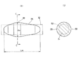
上記第一工程で得られた円柱状の素材32は、上記冷間鍛造成形機10に設けた第一の鍛造ステーションに、向きを変える事なく移動する。そして、第二工程として、上記素材32を、可動型により固定型に、水平方向に打ち込んで、この素材32を軸方向に圧縮する、第一の冷間鍛造(予備成形)を施し、図6に示す様な形状を有する第一中間素材33を造る。この第一中間素材33は、得るべきロッカーアーム1aの長さ方向に関する断面積の変化に対応してその断面積を軸方向に変化させた形状を有する。即ち、上記第一中間素材33は、直径が軸方向中間部で最大となった樽状の形状を有する。即ち、この第一中間素材33は、中間部に設けた、直径が最大となった最大直径部38から軸方向両端に向かう程、直径が小さくなっている。又、この第一中間素材33の軸方向両端面を、ほぼ平坦面としている。尚、上記最大直径部38の軸方向位置は、前記1対の側壁部2a、2aの位置に合わせて規制し、軸方向中間部であるが、必ずしも軸方向中央部ではない。
【0029】
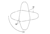
上記第一中間素材33を形成したならば、続いて、上記冷間鍛造成形機10に設けた素材旋回供給装置23(図20参照)により、図7に示す様に、上記第一中間素材33の向きを90度変えつつ、この第一中間素材33を、上記第一の鍛造ステーションから第二の鍛造ステーションに供給する。
【0030】
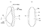
次いで、第三工程として、この第二の鍛造ステーションの可動型により固定型に、上記第一中間素材33を水平方向に打ち込む事により、この第一中間素材33の径方向両側からこの第一中間素材33を圧縮加工する第二の冷間鍛造(第二の予備成形)を施す。そして、図8〜9に示す様な、ロッカーアーム1a(図1〜3)の大まかな形状及び寸法を有する第二中間素材34aを造る。この第二中間素材34aは、1対の側壁部2a、2aと、これら両側壁部2a、2aの幅方向一端縁{図8(a)、図9の右端縁}同士を連結する基部39とを備える。又、この基部39の長さ方向中間部を、上記各側壁部2a、2aと反対側{図8(a)、図9の右側}に少しだけ突出させている。又、本例の場合には、上記第一中間素材33の最大直径部38に対応する位置で、上記第二中間素材34aの各側壁部2a、2aの幅方向{図8(a)、図9の左右方向}の寸法が最大となる様にしている。この様な第二の冷間鍛造を施す第一中間素材33の外周面には予め潤滑皮膜層を形成している為、上記固定型及び可動型の内面と、この第一中間素材33の外面との間で作用する摩擦を小さく抑えられる。そして、この構成により、第二中間素材34aの成形作業性及び形状精度を良好にする。この様な第三工程により得られた第二中間素材34aは、上記固定型と可動型との間から取り出して、第三の鍛造ステーションに供給する。
【0031】
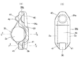
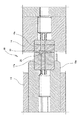
次いで、第四工程として、この第三の鍛造ステーションの可動型44{図10(a)、図12}により固定型43(図12)に、上記第二中間素材34aを水平方向に打ち込む事により、この第二中間素材34aに第三の冷間鍛造(本成形)を施して、図10〜12に示す様な、ロッカーアーム1aの完成品に少し近づいた形状及び寸法を有する、第二中間素材34bを造る。この第二中間素材34bは、上記基部39の長さ方向中間部を、各側壁部2a、2aと反対側に大きく突出させている。又、この基部39の片面{図10(a)の右側面、図10(b)の表側面}の長さ方向両端部を、前記第一、第二の各凹部36、40の大まかな形状及び寸法に形成している。又、上記第三の冷間鍛造では、前記各側壁部2a、2aの形状及び寸法が完成品とほぼ同じになる様に調整する。
【0032】
更に、本例の場合には、上記基部39の長さ方向一端部(図10の下端部)の両側面で、弁体の先端部を突き当てる為の第一の凹部36から幅方向{図10(a)の表裏方向、図10(b)の左右方向、図12の上下方向}に外れた両端部を、上記第三の冷間鍛造を施す際の材料の逃げ部41、41として、これら各逃げ部41、41に固定型43及び可動型44が突き当たらない様にしている。この構成により、これら固定型43と可動型44とに過大な荷重を加わる事を防止でき、これら各型43、44の寿命向上を図れる。この為、ロッカーアーム1aの量産時での単品のコストを低減できる。又、本例の場合には、上記各逃げ部41、41を、上記基部39の長さ方向に関して上記第一の凹部36と同位置と、この第一の凹部36の近くに設けている為、この第一の凹部36を所定の形状及び寸法に精度良く加工し易くできる。
【0033】
更に、上記基部39の長さ方向他端部(図10の上端部)の他面{図10(a)の左側面、図10(b)の裏側面}で、ラッシュアジャスタの先端部を突き当てる為の第二の凹部40と反対側位置を、上記第三の冷間鍛造を施す際の材料の第二の逃げ部42としている。この構成により、上記固定型43と可動型44とに過大な荷重が加わる事を、より効果的に防止できる。又、上述の様に、上記基部39のうちの上記第二の凹部40と反対側位置を第二の逃げ部42としている為、上記第二の凹部40を所定の形状及び寸法に精度良く加工し易くできる。
【0034】
一方、ロッカーアーム1aの完成品の使用時には、各側壁部2a、2aに支持したローラ35の両端面がこれら各側壁部2a、2aの内面に接触する可能性がある。この為、この様にこれら両端面と内面とが接触する場合でも、このローラ35の回転を円滑に行なえる様にすべく、これら各側壁部2a、2aの内面は平坦面とする。この様な第四工程により得られた第二中間素材34bは、上記第三の鍛造ステーションの固定型43と可動型44との間から取り出して、第一の打ち抜きステーションに供給する。
【0035】
次いで、この第一の打ち抜きステーションで行なう孔あけ工程である、第五工程として、固定型と可動型との間で、上記第二中間素材34bのうち、基部39の長さ方向中間部以外の部分を挟持しつつ、この固定型又は可動型の内側に設けた孔あけ用パンチにより、この中間部に打ち抜き加工を施す。そしてこの打ち抜き加工により、図13〜14に示す様な、厚さ方向に貫通する透孔45をその中間部に形成した、第三中間素材46を造る。又、この様に透孔45を形成する事に伴って、各側壁部2a、2aの長さ方向両端部同士を連結する第一、第二の両連結部3a、4aが形成される。更に、上記第五工程では、上記打ち抜き加工と同時に、上記各側壁部2a、2aの幅方向一端部{図13(a)、14の右端部、図13(b)の表側端部}の形状及び寸法を調整する為の鍛造加工を施す事もできる。尚、図14では、上記第三中間素材46と共に、上記打ち抜き加工により上記基部39を打ち抜く事により得た小片(目抜き材)50を合わせて示している。この様な第五工程により得られた第三中間素材46は、上記第一の打ち抜きステーションの可動型と固定型との間から取り出して、第四の鍛造ステーションに供給する。
【0036】
この第四の鍛造ステーションでは、第六工程として、図15〜16に示す様に、可動型48により固定型47に、上記第三中間素材46を水平方向に打ち込む事により、この第三中間素材46に第四の冷間鍛造(サイジング)を施し、第一、第二の各凹部36、40を所定の形状及び寸法に精度良く調整した、図15〜16に示す様な、第四中間素材49を造る。この様な第四の冷間鍛造の場合も、前記第三の冷間鍛造の場合と同様に、第一連結部3aの両側面で、上記第一の凹部36から幅方向{図15(a)の表裏方向、図15(b)の左右方向、図16の上下方向}に外れた両端部を、上記第四の冷間鍛造を施す際の材料の逃げ部41、41として、これら各逃げ部41、41に固定型47及び可動型48が突き当たらない様にしている。そして、この構成により、これら各型47、48の寿命向上を図ると共に、上記第一の凹部36を所定の形状及び寸法に精度良く加工し易くしている。
【0037】
更に、第二の連結部4aの他面{図15(a)の左側面、図15(b)の裏側面}で、第二の凹部40と反対側で対向する位置を、上記第四の冷間鍛造を施す際の材料の第二の逃げ部42としている。そして、この構成により、上記各型47、48の寿命向上を図ると共に、上記第二の凹部40を所定の形状及び寸法に精度良く加工し易くしている。尚、固定型47と可動型48と各逃げ部41、41及び第二の逃げ部42との形状は、本例で示した形状に限らず、必要とする製品形状に基づき変更する事が可能である。
【0038】
尚、上記第四の鍛造ステーションでは、可動型48により固定型47に、上記第三中間素材46を水平方向に打ち込む工程を、必要に応じて繰り返す事により、上記第一、第二の各凹部36、40の形状及び寸法を調整するのと同時に、上記各側壁部2a、2aの平行度の調整や、これら各側壁部2a、2aの内側面同士の間隔及び外側面同士の間隔の調整を行なう事もできる。又、これら各側壁部2a、2aの幅方向一端部に剪断面やかえりが生じた場合に、若干の面押しを行なう事で、この剪断面やかえりを低減、若しくは解消する事もできる。この様な第六工程が終了したならば、上記第四の鍛造ステーションの固定型47と可動型48との間から上記第四中間素材49を取り出して、この第四中間素材49を第二の打ち抜きステーションに供給する。
【0039】
この第二の打ち抜きステーションでは、第七工程として、上記第四中間素材49の各側壁部2a、2aの一部に第二の打ち抜き加工を施して、前述の図1〜3で示したロッカーアーム1aの完成品を造る。本例の場合には、この第二の打ち抜き加工を、前記冷間鍛造成形機10の内部で行なう。この為の方法の一つとして、第四の鍛造ステーションから第二の打ち抜きステーションに上記第四中間素材49を供給する際に、この第二の打ち抜きステーションの固定型及び可動型の先端面と上記各側壁部2a、2aの外側面とが対向する様に、上記第四中間素材49の向きを90度変える方法が考えられる。そして、上記第二の打ち抜きステーションの固定型と可動型との間で、上記第四中間素材49を挟持すると共に、この固定型又は可動型の内側に設けた孔あけ用パンチにより上記各円孔5、5を形成する。又、別の方法として、第四の鍛造ステーションから第二の打ち抜きステーションに上記第四中間素材49を、向きを変更する事なくそのまま供給し、第一〜第四の鍛造ステーションの各可動型44、48を往復移動させる為の駆動機構(スライド機構)の動きを、両側に設けたカム型によりこの往復移動方向と90度異なる方向に変換し、このカム型に取り付けた孔あけ用パンチにより上記各円孔5、5を形成する方法もある。又、本例の場合には、これら各円孔5の軸方向外側の開口端周縁部に面取り37を、これら各円孔5の孔あけ加工と同時に、鍛造加工により形成する。この様にして得られたロッカーアーム1aの完成品は、上記第二の打ち抜きステーションから取り出し用チャックにより、所定位置に取り出す。
【0040】
更に、本例の場合には、前記第二工程で、前記第一中間素材33(図6)の直径が最大となった最大直径部38で、軸方向に対し直交する仮想平面に関する断面積をS {図6(b)}とした場合に、S が所定の関係を満たす様に、上記第一中間素材33を所定の形状及び寸法に加工する。即ち、得るべきロッカーアーム1aの完成品を構成する1対の側壁部2a、2aのうち、長さ方向に関して上記第一中間素材33の最大直径部38に対応する位置で、この長さ方向に対し直交する仮想平面に関する断面形状a 、a (図17)の面積の合計をS とする。又、前記第五工程に於いて、打ち抜き加工で基部39を打ち抜く事により得るべき小片50(図14)の、長さ方向(図14の表裏方向)に関して上記第一中間素材33の最大直径部38に対応する位置で、この長さ方向に対し直交する仮想平面に関する断面形状a (図17)の面積をS とする。そして、この場合に、上記第一中間素材33の形状及び寸法を、S ≧S +S の関係を満たす様に規制する。
【0041】
又、本例の場合には、上記第一中間素材33の上記最大直径部38での直径d38{図6(a)}を、得るべきロッカーアーム1aの完成品を構成する1対の側壁部2a、2a(図1〜3)のうち、長さ方向に関して上記最大直径部38に対応する位置での、これら両側壁部2a、2aの外側面同士の間隔L {図1(b)}とほぼ同じにする(d38≒L)。又、本例の場合には、上記第一中間素材33の軸方向の全長L38{図6(a)}を、得るべきロッカーアーム1aの全長L {図1(b)}とほぼ同じ大きさにする(L38≒L )。
【0042】
上述の様に構成する本例のロッカーアームの製造方法の場合には、軽量なロッカーアーム1aを安価に造れる。即ち、本例の場合には、多段式の冷間鍛造成形機を利用してロッカーアーム1aを製造できる製造工程を設定したので、製造の自動化が容易で、作業性が優れると共に、製造時間の短縮が図れる為、大幅な製造コストの低減が図れる。しかも、本例の場合には、第二工程として、所定長さの素材32に第一の冷間鍛造を施して、その直径が軸方向中間部で最大となった樽状の第一中間素材33を造っている。次いで、第三工程として、この樽状の第一中間素材33に第二の冷間鍛造を施して、ロッカーアーム1aの大まかな形状及び寸法を有する第二中間素材34aを造っている。この為、本例の様に、上記ロッカーアーム1aを構成する各側壁部2a、2aを、幅方向寸法が長さ方向中央寄りから長さ方向両端に向かう程小さくなる形状である、略三角形とするのにも拘らず、上記第二の冷間鍛造を施すべき第一中間素材33の形状を、この第二の冷間鍛造により得るべき第二中間素材34aの形状に近付ける事ができる。即ち、この第一中間素材33の形状を、この第二中間素材34aの場合と同様に、長さ方向に対し直交する方向に関する断面積が、長さ方向中央寄りから長さ方向両端に向かう程小さくなった形状とする事ができる。又、上記各側壁部2a、2aを略三角形としている為、前記支持軸の両端部を支持する為の円孔5、5の形成を可能にしつつ、ロッカーアーム1aの軽量化を図れる。従って、本例の場合には、軽量なロッカーアーム1aを得られると共に、除去すべきバリの発生をなくす事ができる。この様に、バリの発生がない様に、各工程を設定し、素材32及び中間素材33、34a、34b、46、49の形状を設定したので、材料費の低減を図れると共に、バリを除去する工程やこの除去の機構、除去したバリを排出する機構が何れも不要になり、冷間鍛造成形機10の金型の構造を簡略にできる。
【0043】
しかも、上記第二の冷間鍛造での、上記第一中間素材33の塑性変形量を少なくできる為、冷間鍛造に使用する型に過大な荷重が加わる事を防止でき、この型の耐久性の向上を図れる。この為、ロッカーアーム1aの量産時での単品のコストを低減できる。又、上記第一中間素材33は、本例の様に、軸方向に圧縮する事により樽状に形成できる為、上記ロッカーアーム1aを得る為の金属線材として、直径が小さいものを使用できる。これらの結果、軽量なロッカーアーム1aを、安価に造れる。又、上記第一中間素材33を中心軸に関し対称な形状としている為、鍛造時にこの第一中間素材33の中心軸に関する(回転方向の)位相を規制する必要がない。
【0044】
更に、本例の場合には、前記第二工程で得られる、上記第一中間素材33の最大直径部38に関する断面積をS とし、得るべきロッカーアーム1aを構成する1対の側壁部2a、2aのこの最大直径部38に対応する位置での断面積の合計をS とし、第五工程に於いて、打ち抜き加工で基部39を打ち抜く事により得るべき小片50の、上記最大直径部38に対応する位置での断面積をS とした場合に、S ≧S +S を満たす様にしている。この為、上記第三工程で、第二の冷間鍛造を行なう際に、第一中間素材33の最大直径部38付近から他の部分に材料を押し出しつつ、この第一中間素材33の各部を塑性変形させる事ができ、成形性を良好にできる。又、この様に第一中間素材33の断面を規制している為、上記各側壁部2a、2aの一部でヒケ(欠肉)が生じると言った、材料の不足を防止する事ができる。
【0045】
更に、本例の場合には、上記第一中間素材33の上記最大直径部38での直径d38を、得るべきロッカーアーム1aの完成品を構成する1対の側壁部2a、2aのうち、長さ方向に関してこの最大直径部38に対応する位置での、これら両側壁部2a、2aの外側面同士の間隔L とほぼ同じにしている(d38≒L )。この為、上記第二の冷間鍛造での、上記第一中間素材33の塑性変形量を少なくできて、冷間鍛造に使用する型に過大な荷重が加わる事をより効果的に防止でき、この型の耐久性の向上を図れる。この為、ロッカーアーム1aの量産時での単品のコストを、より低減できる。又、上記間隔L と上記最大直径部での直径d38とをほぼ同じにしている為、上記第二の冷間鍛造の際に、上記第一中間素材33を上記両側壁部2a、2aの厚さ方向{図1(b)の左右方向}に規制でき、形状精度を良好にできる。
【0046】
又、本例の場合には、上記第一中間素材33の軸方向の全長L38{図6(a)}を、得るべきロッカーアーム1aの全長L {図1(b)}とほぼ同じ大きさにしている(L38≒L )。この為、上記第二の冷間鍛造での、上記第一中間素材33の軸方向の位置決めを容易に行なえる。この為、冷間鍛造に使用する型に過大な荷重や偏荷重が加わる事を、より効果的に防止でき、この型の耐久性をより向上できる。又、ロッカーアーム1aの形状精度を良好にできる。
【0047】
尚、本例の場合には、各側壁部2a、2aに設ける各円孔5、5を打ち抜き加工により形成しているが、本発明では、これら各円孔5、5を、この打ち抜き加工の代わりに、シェービング加工や、切削加工により形成する事もできる。但し、このうちの切削加工を採用する場合には、ロッカーアームのコストが上昇する原因となる。この為、このロッカーアーム1aのコストの低減を図る面からは、上記各円孔5、5を、打ち抜き加工又はシェービング加工により形成する事が好ましく、より好ましくは、このうちの打ち抜き加工により上記各円孔5、5を形成する。又、冷間鍛造成形機10から取り出した中間素材を別のプレス加工機に搬送して、この別のプレス加工機で上記各円孔5、5の打ち抜き加工を行なう事もできる。
【0048】
又、本例の場合には、金属線材に予めリン酸亜鉛皮膜等の潤滑皮膜層を形成している。但し、冷間鍛造成形機10の金型の内面に潤滑剤を塗布したり、冷間鍛造成形機10の内部に潤滑油を供給する等により、素材32及び第一〜第四中間素材33、34a、34b、46、49の外面と金型の内面との間での摩擦を抑える事もできる。
【0049】
【発明の効果】
本発明は、以上に述べた通り構成され作用するので、軽量なロッカーアームを安価に得られる。
【図面の簡単な説明】
【図1】本発明の実施の形態の1例により得られるロッカーアームの完成品を示しており、(a)は断面図、(b)は(a)の右方から見た図。
【図2】図1(a)のA−A断面図。
【図3】同B−B断面図。
【図4】ロッカーアームの製造方法を示すフローチャート。
【図5】同製造方法の第一工程により得られる素材を示しており、(a)は正面図、(b)は(a)の側方から見た図。
【図6】第二工程により得られる第一中間素材を示しており、(a)は正面図、(b)は(a)のC−C断面図。
【図7】第一の鍛造ステーションから第二の鍛造ステーションへ第一中間素材を移動する際にこの第一中間素材の向きを90度変える状態を示す図。
【図8】第三工程により得られる第二中間素材を示しており、(a)は断面図、(b)は(a)の右方から見た図。
【図9】図8(a)のD−D断面図。
【図10】第四工程により得られる第二中間素材を示しており、(a)は断面図、(b)は(a)の右方から見た図。
【図11】図10(a)のE−E断面図。
【図12】第四工程の鍛造作業の途中の状態を、図10(a)のF−F断面部分で示す図。
【図13】第五工程により得られる第三中間素材を示しており、(a)は断面図、(b)は(a)の右方から見た図。
【図14】同第三中間素材と、第五工程の打ち抜き加工時に生じた小片とを、図13(a)のG−G断面部分で示す図。
【図15】第六工程により得られる第四中間素材を示しており、(a)は断面図、(b)は(a)の右方から見た図。
【図16】第六工程の鍛造作業の途中の状態を、図15(a)のH−H断面部分で示す図。
【図17】得るべきロッカーアームを構成する1対の側壁部の、第一中間素材の最大直径部に対応する位置での断面形状と、第五工程で打ち抜き加工により生じる小片のこの最大直径部に対応する位置での断面形状とを示す図。
【図18】従来から知られたロッカーアームの製造方法により得られたロッカーアームを示しており、(a)は正面図、(b)は(a)の左方から見た図。
【図19】従来から知られたロッカーアームの製造方法によりロッカーアームを製造する状態を示す略斜視図。
【図20】同製造方法に使用する冷間鍛造成形機の部分断面図。
【図21】第一工程により所定長さに切断した素子を示す斜視図。
【図22】冷間鍛造成形機の第一の鍛造ステーションを示す、図20の部分拡大断面図。
【図23】同第一の打ち抜きステーションを示す、図20の部分拡大断面図。
【図24】同第二の鍛造ステーションを示す、図20の部分拡大断面図。
【図25】同第二の打ち抜きステーションを示す、図20の部分拡大断面図。
【符号の説明】
1、1a ロッカーアーム
2、2a 側壁部
3、3a 第一の連結部
4、4a 第二の連結部
5 円孔
6 第一の係合部
7 第二の係合部
8 回転支持装置
9 金属線材
10 冷間鍛造成形機
11 ローラ式線材供給機構
12 切断機構
13 素材
14 ダイブロック
15 ラム
16a〜16d 固定型
17a〜17d 可動型
18a〜18d 型ホルダ
19 第一の鍛造ステーション
20 第一の打ち抜きステーション
21 第二の鍛造ステーション
22 第二の打ち抜きステーション
23 素材旋回供給機構
24 第一中間素材
25、25a、25b バリ
26 通孔
27 押し出し部材
28 孔あけ用パンチ
29 透孔
30 第二中間素材
31 第三中間素材
32 素材
33 第一中間素材
34a、34b 第二中間素材
35 ローラ
36 第一の凹部
37 面取り
38 最大直径部
39 基部
40 第二の凹部
41 逃げ部
42 第二の逃げ部
43 固定型
44 可動型
45 透孔
46 第三中間素材
47 固定型
48 可動型
49 第四中間素材
50 小片
[0001]
TECHNICAL FIELD OF THE INVENTION
The present invention relates to a method of manufacturing a rocker arm incorporated in a valve mechanism of an engine to convert rotation of a camshaft into reciprocating motion of a valve body (an intake valve and an exhaust valve).
[0002]
[Prior art]
The reciprocating engine (reciprocating piston engine) is provided with an intake valve and an exhaust valve that open and close in synchronization with the rotation of the crankshaft, except for some two-stroke engines. In such a reciprocating engine, the movement of the camshaft rotating in synchronization with the rotation of the crankshaft (at a rotation speed of 1/2 in the case of a four-cycle engine) is controlled by the rocker arm to the intake valve and the exhaust valve. And the intake and exhaust valves may reciprocate in their respective axial directions.
[0003]
Conventionally, a cast product (a cast iron product or an aluminum die-cast product) has been generally used as a rocker arm to be incorporated in such a valve operating mechanism of an engine. In recent years, it has been considered that the rocker arm is made by pressing a metal plate such as a steel plate. However, in the case of such a rocker arm made of a cast product or a rocker arm made of a metal plate, there is a problem that the cost is increased due to an increase in the time required for the manufacturing operation and an increase in waste of material. is there.
[0004]
On the other hand, as described in Patent Document 1, there has been proposed a method of manufacturing a rocker arm by cold forging a material (blank) obtained by cutting a metal wire into a predetermined length. I have. According to Patent Literature 1, when a rocker arm is formed by forming a lubricating coating layer on a material made of a metal wire and performing cold forging, the rocker arm can be manufactured with high accuracy without cracks, thereby improving workability. I can do it. In addition, when the rocker arm is manufactured by such cold forging, the shape accuracy and the dimensional accuracy can be increased as compared with the case where the rocker arm is manufactured by hot forging. 18 to 25 show an invention related to a method for manufacturing a rocker arm described in Patent Document 1. FIG. The method of manufacturing the rocker arm is described in detail in Patent Document 1 described above, and will be briefly described here. As shown in FIG. 18, the rocker arm 1 includes a pair of side walls 2, 2 which are substantially parallel to each other, and a first connecting portion 3 which connects these two side walls 2, 2 at both ends in the longitudinal direction. And a second connecting portion 4. Among these first connection part 3 and second connection part 4, the first connection part 3 is provided with a first engagement part 6 for abutting the base end of the valve body, and a second connection part. 4 has a second engagement portion 7 for abutting a tip end of a swing support member such as a lash adjuster.
[0005]
Although not described in Patent Document 1, in the case of a rocker arm that is actually used, a pair of circular holes are formed concentrically with each other at the longitudinally intermediate portions of the side walls 2 and 2. Both ends of a support shaft for rotatably supporting a roller engaged with a cam are freely supported in these circular holes. Each of the side walls 2, 2 is formed in a substantially rhombic shape.
[0006]
The operation of manufacturing the rocker arm 1 as described above is performed as follows. First, as shown in FIG. 19, the end of the metal wire 9 wound in a coil shape around the rotation support device 8 is pulled out by a roller type wire feeding mechanism 11 provided in a cold forging machine 10. It is introduced into the forging machine 10. The metal wire 9 has a rectangular cross section. The metal wire 9 is previously immersed in a lubricating liquid tank such as zinc phosphate to form a lubricating film layer on the outer peripheral surface of the metal wire 9. As a first step, as shown in FIG. 20, a cutting mechanism 12 provided in the cold forging machine 10 cuts the metal wire 9 to a predetermined length, thereby forming a rectangular parallelepiped as shown in FIG. A blank material 13 is formed. The cold forging machine 10 is a so-called horizontal multi-stage forging machine. The cold forging machine 10 is provided with a die block 14 fixed inside and a horizontal so as to approach or separate from the die block 14 (moving far and near). And a ram 15 reciprocating in the direction. In the die block 14, a plurality of fixed dies 16a to 16d are arranged at intervals in the horizontal direction. In addition, a plurality of movable dies 17a to 17d are arranged at portions of the ram 15 facing the fixed dies 16a to 16d via mold holders 18a to 18d, respectively. The first forging station 19, the first punching station 20, the second forging station 21, and the second punching station 22 are provided at portions where the fixed dies 16 a to 16 d and the movable dies 17 a to 17 d are arranged. Are provided. The material 13 having a rectangular parallelepiped shape obtained in the first step is rotated by 90 degrees by the material turning supply mechanism 23 provided in the cold forging machine 10, while the direction of the material 13 is changed by 90 degrees. To supply.
[0007]
In the first forging station 19, as a second step, as shown in detail in FIG. 22, the material 13 is horizontally driven into the fixed die 16a by the movable die 17a, so that the material 13 is cold forged. To produce the first intermediate material 24 having the approximate shape and dimensions of the rocker arm 1. At this time, a burr 25 is formed on the outer peripheral surface of the intermediate portion in the thickness direction of the first intermediate material 24 over the entire circumference. Since a lubricating film layer is formed in advance on the outer peripheral surface of the material 13 to be subjected to such cold forging, it acts between the inner surfaces of the fixed mold 16a and the movable mold 17a and the outer surface of the material 13. Friction can be kept small. With this configuration, the workability and the shape accuracy of the first intermediate material 24 can be improved. The first intermediate material 24 obtained in the second step is taken out from between the fixed die 16a and the movable die 17a and supplied to the first punching station 20.
[0008]
In the first punching station 20, as a third step, as shown in detail in FIG. 23, the distal end surface of a cylindrical pushing member 27 provided in the through hole 26 of the fixed die 16b and the cylindrical movable die The main body portion of the first intermediate material 24 excluding the burrs 25 is sandwiched between the front end surface of the first intermediate material 24 and the tip surface of the first intermediate material 17b. Then, by pulling the main body portion into the through hole 26, the burr 25 is removed at the periphery of the opening end of the through hole 26. At the same time, an intermediate portion of the first intermediate material 24 is punched by a punch 28 provided inside the extruding member 27 to produce a second intermediate material 30 having a through hole 29. The second intermediate material 30 obtained in the third step is taken out from between the fixed die 16b and the movable die 17b and supplied to the second forging station 21.
[0009]
In the second forging station 21, as a fourth step, as shown in detail in FIG. 24, the second intermediate material 30 is driven in a horizontal direction into a fixed mold 16c by a movable mold 17c. The material 30 is subjected to cold forging to produce a third intermediate material 31 having a size and shape close to a finished product. At this time, burrs 25a and 25b are formed on the outer peripheral surface in the thickness direction intermediate portion of the third intermediate material 31 and the inner peripheral surface of the through hole 29, respectively. Since the lubricating film layer is formed in advance on the outer surface of the second intermediate material 30 that performs such cold forging, the inner surface of the fixed die 16c and the movable die 17c and the outer surface of the second intermediate material 30 The friction between them can be kept small. With this configuration, the workability and shape accuracy of the third intermediate material 31 can be improved. When the fourth step is completed, the third intermediate material 31 is taken out from between the fixed die 16c and the movable die 17c, and the third intermediate material 31 is supplied to the second punching station 22. I do.
[0010]
In the second punching station 22, as a fifth step, as shown in detail in FIG. 25, similar to the case of the third step, burrs 25a formed on the outer peripheral surface of the third intermediate material 31 are removed. Remove. At the same time, the burr 25b formed on the inner peripheral surface of the through hole 29 of the third intermediate material 31 is also removed to obtain a completed rocker arm 1. The rocker arm 1 is taken out from between the fixed die 16d and the movable die 17d of the second punching station 22 to a predetermined position by, for example, a take-out chuck (not shown). Although not described in Patent Document 1, in the case of a rocker arm that is actually used, another processing machine is used to bring the rocker arm into a position where it is aligned with each other at an intermediate portion of each side wall 2 (see FIG. 18). Drilling for forming a pair of circular holes is performed.
[0011]
In the case of the rocker arm manufacturing method described in Patent Document 1 configured as described above, since the rocker arm 1 is manufactured by a multi-stage cold forging machine, the time required for the manufacturing operation can be reduced to some extent. Workability can be improved.
[0012]
[Patent Document 1]
JP-A-10-328778
[0013]
[Problems to be solved by the invention]
In the case of the method for manufacturing a rocker arm described in Patent Document 1 described above, burrs 25, 25a, and 25b are formed on a part of the first intermediate material 24 and the third intermediate material 31. For this reason, material costs are increased by the burrs 25, 25a and 25b. In particular, in the case of the rocker arm manufacturing method described in Patent Document 1, the burrs 25, 25a, and 25b have a large volume. Next, the reason will be described. The rocker arm 1 obtained by the rocker arm manufacturing method described in Patent Document 1 has a pair of side walls 2 and 2 formed in a substantially rhombic shape. Along with this, the first intermediate material 24 produced in the second step at the first forging station 19 is formed into a H-shaped cross section in the width direction of a portion to be each side wall 2 (see FIG. 18). The dimensions are such that the dimensions become smaller from the center in the longitudinal direction to both ends in the longitudinal direction. On the other hand, the material 13 to be subjected to cold forging in the second step has a rectangular parallelepiped shape in which the area of the cross-sectional shape in the direction orthogonal to the axial direction (length direction) does not change over the entire axial length. . That is, in the case of the rocker arm manufacturing method described in Patent Literature 1, the cold working is performed in spite of the fact that the cross-sectional area of the first intermediate material 24 to be obtained by cold forging changes in the longitudinal direction. The material 13 to be forged has a rectangular parallelepiped shape whose cross-sectional area does not change over the entire length in the axial direction. As described above, when the shape to be obtained by the cold forging and the shape of the material 13 to be subjected to the cold forging are largely different, the volumes of the burrs 25, 25a, and 25b to be removed in the subsequent process are large.
[0014]
In addition, it is a matter that a person skilled in the art can easily perform the processing by actively producing burrs, and the processing can be performed relatively easily. That is, the shape and size of the product largely depend on the shape and size of a mold for processing a material or an intermediate material to obtain the product. Therefore, if the volume of the raw material or intermediate material is slightly larger than the volume of the product to be obtained, the processing for obtaining the product can be easily performed, and the surplus portion generated each time processing is performed as burrs. Then, the excision treatment may be performed in a later step.
However, if many burrs to be removed by cold forging occur, not only a separate step for removing the burrs is required, but also material costs increase. For this reason, in the case of the rocker arm manufacturing method described in Patent Document 1, there is still room for reducing the cost of the rocker arm 1.
In view of such circumstances, the manufacturing method of the rocker arm of the present invention is performed by cold forging by setting a process so as not to generate burrs or to reduce the burrs even when they are generated. It was invented to obtain a rocker arm at low cost.
[0015]
[Means for Solving the Problems]
The method for manufacturing a rocker arm according to the present invention is a method for manufacturing a rocker arm by cutting a metal wire having a circular cross section to a predetermined length by cold forging a material obtained by cutting the metal wire into a predetermined length. , And a pair of connecting portions for connecting the both side portions near both ends in the longitudinal direction thereof, and each of the connecting portions includes an engaging portion that engages with the valve element or the swing support member. And a rocker arm having the same.
In order to manufacture this rocker arm, in the method for manufacturing a rocker arm according to claim 1, a cross-sectional area in the length direction of the rocker arm to be obtained by subjecting the material to first cold forging. A step of producing a first intermediate material whose sectional area is changed in the axial direction in accordance with the change of the first intermediate material, and by performing at least a second cold forging on the first intermediate material, the above-mentioned side walls and each of these A step of producing a second intermediate material provided with a base that connects a part of the side wall portions, and performing a drilling process to form a through hole in a longitudinal middle portion of the base of the second intermediate material, Perforating a third intermediate material provided with the pair of connecting portions.
[0016]
A rocker arm manufacturing method according to a second aspect is the rocker arm manufacturing method according to the first aspect, wherein the first intermediate forging is performed by subjecting the material to a first cold forging. The material is barrel-shaped, the diameter of which is greatest at the axial middle part.
[0017]
The rocker arm manufacturing method according to claim 3 is the rocker arm manufacturing method according to claim 1 or 2, wherein the diameter of the first intermediate material is the largest. In the diameter section, the cross-sectional area on an imaginary plane orthogonal to the axial direction is represented by S 1 At a position corresponding to the maximum diameter portion of the first intermediate material with respect to the length direction of the pair of side wall portions constituting the rocker arm to be obtained, the cross-sectional area of a virtual plane orthogonal to the length direction. Sum S 2 In the drilling step, in a position corresponding to the maximum diameter portion of the first intermediate material with respect to the length direction of the small pieces generated by punching the base in the punching process, which is a drilling process, in this length direction On the other hand, the sectional area of a virtual plane orthogonal to 3 And the shape and dimensions of the first intermediate material are S 1 ≧ S 2 + S 3 Regulate to satisfy.
[0018]
Also, preferably, as described in claim 4, in the rocker arm manufacturing method according to any one of claims 1 to 3, the diameter of the first intermediate material at the maximum diameter portion is adjusted. The distance between the outer surfaces of the two side walls at a position corresponding to the maximum diameter portion in the length direction of the pair of side walls constituting the rocker arm to be obtained is substantially the same.
[0019]
Preferably, in the method for manufacturing a rocker arm according to any one of claims 1 to 4, as described in claim 5, the total length in the axial direction of the first intermediate material should be obtained. Make the overall length of the rocker arm approximately the same.
[0020]
[Action]
In the case of the rocker arm manufacturing method of the present invention configured as described above, the shape of the material and the intermediate material, and the steps after the first cold forging, depending on the shape of the product of the rocker arm to be obtained, By properly setting the burrs, it is possible to eliminate the generation of burrs to be removed, or to suppress the burrs even if they occur. For example, when the shape of the first intermediate material is set as in the method of manufacturing a rocker arm described in claim 2, each of the side wall portions has a substantially rhombic shape, a substantially triangular shape, or the like, and the width dimension is closer to the center in the length direction. When a rocker arm having a shape that becomes smaller toward both ends in the length direction is formed, it is possible to eliminate the generation of burrs to be removed or to suppress the generation of burrs even if they are generated. If the width of the rocker arm is reduced from the center in the length direction toward both ends in the length direction as described above, the weight of the rocker arm can be reduced. Moreover, since the amount of plastic deformation of the first intermediate material in the second cold forging can be reduced, it is possible to prevent an excessive load from being applied to the mold used for the cold forging, and to improve the durability of the mold. I can do it. For this reason, the cost of the rocker arm in mass production can be reduced. Further, since the first intermediate material can be formed into a barrel shape by being compressed in the axial direction, a metal wire having a small diameter can be used as a metal wire for obtaining the rocker arm. As a result, a lightweight rocker arm can be manufactured at low cost. Since the first intermediate material has a symmetrical shape with respect to the central axis, it is not necessary to regulate the phase of the first intermediate material in the rotation direction with respect to the central axis during forging. In addition, if a horizontal multi-stage cold forging machine, which is a well-known manufacturing machine, is used, manufacturing can be easily automated, workability can be improved, and manufacturing time can be shortened, thereby significantly reducing manufacturing cost. . If burrs can be eliminated, material costs can be further reduced, and a mechanism for removing and discharging burrs is not required, simplifying the mold structure of the cold forging machine. it can. Further, the dimensional accuracy and surface accuracy of the obtained rocker arm can be improved.
[0021]
Further, in the case of the rocker arm manufacturing method according to the third aspect, when performing the second cold forging, while extruding the material from near the maximum diameter portion of the first intermediate material to another portion, the second cold forging is performed. Each part of one intermediate material can be plastically deformed, and the formability can be improved.
[0022]
Further, according to the preferred configuration described in claim 4, since the amount of plastic deformation of the first intermediate material in the second cold forging can be reduced, an excessive load is applied to the mold used for the cold forging. It can be more effectively prevented from being added, and the durability of the mold can be further improved. Therefore, the cost of the rocker arm in mass production can be further reduced. In addition, at the time of the second cold forging, the position of the first intermediate material 33 can be regulated in the thickness direction of both side walls, so that the shape accuracy can be improved.
[0023]
Further, according to the preferred configuration of the fifth aspect, since the positioning of the first intermediate material in the axial direction in the second cold forging can be easily performed, the die used for the cold forging is excessively large. It is possible to more effectively prevent a large load or an unbalanced load from being applied, and the durability of the mold can be further improved. Further, the shape accuracy of the rocker arm can be improved.
[0024]
BEST MODE FOR CARRYING OUT THE INVENTION
1 to 17 show an example of an embodiment of the present invention. The feature of this example is that a second step of obtaining a first intermediate material 33 having a predetermined shape is a pre-process of a third step for obtaining a second intermediate material 34a having a rough shape and dimensions of the rocker arm 1a. Is provided so that the lightweight rocker arm 1a can be manufactured at low cost. The manufacturing apparatus of the rocker arm 1a is substantially the same as the manufacturing apparatus shown in FIGS. 18 to 25, and thus the duplicate description will be omitted or simplified, and the following description will focus on the features of this example. .
[0025]
As shown in FIGS. 1 to 3, the rocker arm 1a of the present embodiment has a pair of side walls 2a, 2a substantially parallel to each other and formed in a substantially triangular shape, and a longitudinal direction of these side walls 2a, 2a (see FIGS. 1 (up-down direction of 1) It has the 1st connection part 3a and the 2nd connection part 4a which connect both ends. Further, a pair of circular holes 5, 5 are formed concentrically with each other at the longitudinally intermediate portions of both side walls 2, 2, and a roller 35 engaging with a cam is rotated in these circular holes 5, 5. Both ends of the support shaft for freely supporting are freely supported.
[0026]
Further, in order to abut the base end of the valve body, the first connecting portion 3a has a first surface (a right side surface in FIGS. 1A and 2 and a front side surface in FIG. 1B). A first concave portion 36 which is an engaging portion is formed. Further, in order to abut the tip of the lash adjuster, one end of the second connecting portion 4a (the right side surface in FIG. 1A, the front side surface in FIG. 1B) is engaged with the second engaging portion. A certain second concave portion 40 is formed. In the case of this example, an example is shown in which a lash adjuster as a swing support member is engaged with the second engaging portion. However, a screw hole is formed in the second connecting portion 4a, and the screw hole is formed. The present invention can be applied to a structure in which an adjusting screw is screwed to a portion. In the case of this example, as shown in detail in FIG. 3, a chamfer 37 in the shape of a squirrel pot having a straight line at the axially outer opening end of each of the circular holes 5 may be formed. it can. The chamfer 37 allows the end of the support shaft to be easily inserted into one of the circular holes 5, and the outer peripheral edges of both ends of the support shaft are fixed to the above-described respective positions. It is used for caulking and fixing to the periphery of the opening end of the circular holes 5,5.
[0027]
The rocker arm 1a of the present embodiment configured as described above is manufactured as shown in FIG. Next, a method of manufacturing the rocker arm 1a will be described in detail. First, the end portion of the metal wire wound in a coil shape around the rotation support device 8 is supplied to the cold forging machine 10 by a roller type wire supply mechanism 11 (see FIG. 19) provided in the cold forging machine 10. Introduce inside. In the case of this example, the cross section of the metal wire is circular. Further, this metal wire is previously immersed in a lubricating solution bath such as zinc phosphate to form a lubricating film layer such as a zinc phosphate film on the outer peripheral surface thereof. Then, as a first step, the metal wire is cut into a predetermined length by a cutting mechanism 12 (see FIG. 20) provided in the cold forging machine 10, thereby obtaining a columnar material as shown in FIG. (Blank) 32 is made. Incidentally, the cold forging machine 10 used for manufacturing the rocker arm in this example is almost the same as the manufacturing apparatus shown in FIGS. Therefore, in the following description, the specific structure of the cold forging machine 10 is omitted or simplified. Further, the cold forging machine 10 used in this example does not generate burrs in the manufacturing process of the rocker arm 1a, unlike those shown in FIGS. 19, 20, and 22 to 25 described above.
[0028]
The columnar material 32 obtained in the first step moves to the first forging station provided in the cold forging machine 10 without changing its direction. Then, as a second step, the raw material 32 is horizontally driven into a fixed die by a movable die, and the raw material 32 is subjected to a first cold forging (preliminary forming) to compress the raw material 32 in the axial direction. A first intermediate material 33 having a shape as shown in FIG. The first intermediate material 33 has a shape in which the cross-sectional area is changed in the axial direction corresponding to the change in the cross-sectional area in the length direction of the rocker arm 1a to be obtained. That is, the first intermediate material 33 has a barrel-like shape having a maximum diameter at the axially intermediate portion. That is, the diameter of the first intermediate material 33 becomes smaller toward the both ends in the axial direction from the maximum diameter portion 38 provided at the intermediate portion and having the largest diameter. The axially opposite end surfaces of the first intermediate material 33 are substantially flat surfaces. The position of the maximum diameter portion 38 in the axial direction is regulated in accordance with the position of the pair of side walls 2a, 2a, and is an intermediate portion in the axial direction, but not necessarily a central portion in the axial direction.
[0029]
After the first intermediate material 33 is formed, subsequently, as shown in FIG. 7, the first intermediate material 33 is provided by the material turning supply device 23 (see FIG. 20) provided in the cold forging machine 10. The first intermediate material 33 is supplied from the first forging station to the second forging station while changing the direction of the first intermediate material 33 by 90 degrees.
[0030]
Next, as a third step, the first intermediate material 33 is horizontally driven into the fixed die by the movable die of the second forging station, so that the first intermediate material 33 is disposed on both sides in the radial direction of the first intermediate material 33. A second cold forging (second preforming) for compressing the material 33 is performed. Then, as shown in FIGS. 8 and 9, a second intermediate material 34a having a rough shape and dimensions of the rocker arm 1a (FIGS. 1 to 3) is manufactured. The second intermediate material 34a includes a pair of side walls 2a, 2a, and a base 39 that connects one end in the width direction of these side walls 2a, 2a {the right end in FIGS. 8A and 9}. Is provided. The base 39 has a lengthwise intermediate portion projecting slightly from the side opposite to the side walls 2a, 2a (the right side in FIGS. 8A and 9). Further, in the case of this example, the width direction of each side wall 2a, 2a of the second intermediate material 34a at a position corresponding to the maximum diameter portion 38 of the first intermediate material 33 {FIG. 9 has a maximum dimension in the left-right direction}. Since the lubricating film layer is previously formed on the outer peripheral surface of the first intermediate material 33 subjected to such second cold forging, the inner surfaces of the fixed and movable dies and the outer surface of the first intermediate material 33 are formed. And the friction acting between them can be kept small. And with this configuration, the molding workability and the shape accuracy of the second intermediate material 34a are improved. The second intermediate material 34a obtained in the third step is taken out from between the fixed mold and the movable mold and supplied to the third forging station.
[0031]
Then, as a fourth step, the second intermediate material 34a is horizontally driven into the movable mold 44 (FIG. 10A, FIG. 12) of the third forging station into the fixed mold 43 (FIG. 12). The second intermediate material 34a is subjected to a third cold forging (main molding) to have a shape and dimensions slightly closer to the finished product of the rocker arm 1a as shown in FIGS. The material 34b is made. The second intermediate material 34b has a lengthwise intermediate portion of the base 39 protruding largely toward the side opposite to the side walls 2a, 2a. Further, one end of the base 39 (the right side surface in FIG. 10A, the front side surface in FIG. 10B) is formed by forming both ends in the longitudinal direction of the first and second concave portions 36 and 40 into a rough shape. And dimensions. In the third cold forging, the shapes and dimensions of the side walls 2a, 2a are adjusted so as to be substantially the same as the finished product.
[0032]
Further, in the case of the present example, the first concave portion 36 for abutting the distal end portion of the valve body on both side surfaces of one longitudinal end portion (lower end portion in FIG. 10) of the base portion 39 in the width direction. 10 (a), the left and right directions in FIG. 10 (b), and the both ends deviated in the vertical direction の in FIG. 12 are used as the escape portions 41, 41 of the material when performing the third cold forging. The fixed mold 43 and the movable mold 44 are prevented from abutting on these escape portions 41, 41. With this configuration, it is possible to prevent an excessive load from being applied to the fixed mold 43 and the movable mold 44, and to improve the life of each of the molds 43 and 44. For this reason, the cost of the rocker arm 1a at the time of mass production can be reduced. Further, in the case of the present example, the relief portions 41 are provided at the same position as the first concave portion 36 in the longitudinal direction of the base portion 39 and near the first concave portion 36. The first concave portion 36 can be easily processed into a predetermined shape and size with high accuracy.
[0033]
Further, the other end of the base 39 in the longitudinal direction (upper end in FIG. 10) is pushed on the other surface {the left side surface in FIG. 10A and the back side surface in FIG. A position opposite to the second concave portion 40 to be applied is a second escape portion 42 of a material when the third cold forging is performed. With this configuration, it is possible to more effectively prevent an excessive load from being applied to the fixed die 43 and the movable die 44. Further, as described above, the position of the base 39 opposite to the second recess 40 is defined as the second relief portion 42, so that the second recess 40 is accurately processed into a predetermined shape and size. Can be easily done.
[0034]
On the other hand, when the finished product of the rocker arm 1a is used, there is a possibility that both end surfaces of the roller 35 supported on the side walls 2a, 2a come into contact with the inner surfaces of the side walls 2a, 2a. For this reason, even if the both end surfaces and the inner surface come into contact with each other, the inner surfaces of the side walls 2a and 2a are flat surfaces so that the rotation of the roller 35 can be performed smoothly. The second intermediate material 34b obtained in such a fourth step is taken out from between the fixed die 43 and the movable die 44 of the third forging station and supplied to the first punching station.
[0035]
Next, as a fifth step, which is a hole punching step performed in the first punching station, between the fixed mold and the movable mold, the second intermediate material 34b, except for the longitudinal direction intermediate portion of the base 39, of the second intermediate material 34b. The intermediate portion is punched by a punch for punching provided inside the fixed or movable die while holding the portion. Then, as shown in FIGS. 13 and 14, a third intermediate material 46 having a through hole 45 penetrating in the thickness direction formed at an intermediate portion thereof is produced by this punching process. In addition, with the formation of the through hole 45 in this manner, first and second connecting portions 3a and 4a for connecting both longitudinal end portions of the side walls 2a and 2a are formed. Further, in the fifth step, at the same time as the punching, the shape of one end in the width direction of each of the side walls 2a, 2a {the right end in FIGS. 13 (a) and 14; the front end in FIG. 13 (b)}. Forging for adjusting the dimensions can also be performed. In FIG. 14, together with the third intermediate material 46, a small piece (cutout material) 50 obtained by punching the base 39 by the punching process is also shown. The third intermediate material 46 obtained in the fifth step is taken out from between the movable die and the fixed die of the first punching station and supplied to the fourth forging station.
[0036]
In the fourth forging station, as a sixth step, as shown in FIGS. 15 and 16, the third intermediate material 46 is horizontally driven into the fixed die 47 by the movable die 48, thereby forming the third intermediate material. A fourth intermediate material, as shown in FIGS. 15 and 16, in which a fourth cold forging (sizing) is applied to 46 and the first and second concave portions 36 and 40 are precisely adjusted to predetermined shapes and dimensions. Build 49. In the case of such a fourth cold forging, similarly to the case of the third cold forging, the width direction from the first concave portion 36 on both side surfaces of the first connecting portion 3a {FIG. ), The left and right directions in FIG. 15B and the vertical direction 上下 in FIG. 16 are used as the escape portions 41 of the material at the time of performing the fourth cold forging. The fixed mold 47 and the movable mold 48 do not abut on the parts 41, 41. With this configuration, the life of each of the dies 47 and 48 is improved, and the first concave portion 36 is easily processed into a predetermined shape and size with high accuracy.
[0037]
Further, on the other surface of the second connecting portion 4a (the left side surface in FIG. 15A, the back side surface in FIG. 15B), the position facing the second concave portion 40 on the opposite side is referred to as the fourth surface. The second relief portion 42 is made of a material when cold forging is performed. With this configuration, the life of each of the dies 47 and 48 is improved, and the second recess 40 is easily processed into a predetermined shape and size with high accuracy. The shapes of the fixed mold 47, the movable mold 48, the reliefs 41, 41, and the second relief 42 are not limited to the shapes shown in this example, and can be changed based on the required product shape. It is.
[0038]
In the fourth forging station, the step of horizontally driving the third intermediate material 46 into the fixed mold 47 by the movable mold 48 is repeated as necessary, so that the first and second concave portions are formed. At the same time as adjusting the shapes and dimensions of 36 and 40, adjustment of the parallelism of the side walls 2a and 2a, and adjustment of the space between the inner surfaces and the space between the outer surfaces of the side walls 2a and 2a are performed. You can do it. Further, when a shear surface or a burr occurs at one end in the width direction of each of the side wall portions 2a, 2a, by slightly pressing the surface, the shear surface or the burr can be reduced or eliminated. When the sixth step is completed, the fourth intermediate material 49 is taken out from between the fixed die 47 and the movable die 48 of the fourth forging station, and the fourth intermediate material 49 is placed in the second forging station. Supply to the punching station.
[0039]
In the second punching station, as a seventh step, a second punching process is performed on a part of each of the side walls 2a, 2a of the fourth intermediate material 49, and the rocker arm shown in FIGS. Build the finished product of 1a. In the case of this example, the second punching is performed inside the cold forging machine 10. As one of the methods for this, when supplying the fourth intermediate material 49 from the fourth forging station to the second punching station, the leading end surfaces of the fixed and movable dies of the second punching station and the A method of changing the direction of the fourth intermediate material 49 by 90 degrees so that the outer surfaces of the side walls 2a and 2a face each other is considered. Then, the fourth intermediate material 49 is sandwiched between the fixed die and the movable die of the second punching station, and each of the circular holes is formed by a punch for punching provided inside the fixed die or the movable die. 5 and 5 are formed. As another method, the fourth intermediate material 49 is supplied from the fourth forging station to the second punching station as it is without changing the direction, and each movable mold 44 of the first to fourth forging stations is supplied. , 48 for reciprocating movement of the drive mechanism (slide mechanism) is converted into a direction different from the reciprocating movement direction by 90 degrees by cam dies provided on both sides, and the above-mentioned hole is punched by the punch for punching attached to the cam type. There is also a method of forming the respective circular holes 5,5. Further, in the case of the present example, a chamfer 37 is formed on the peripheral edge of the opening end on the outside in the axial direction of each of the circular holes 5 by forging at the same time as the drilling of the circular holes 5. The finished product of the rocker arm 1a thus obtained is taken out from the second punching station to a predetermined position by a takeout chuck.
[0040]
Further, in the case of the present example, in the second step, the cross-sectional area with respect to a virtual plane orthogonal to the axial direction at the maximum diameter portion 38 where the diameter of the first intermediate material 33 (FIG. 6) is the largest. S 1 When {FIG. 6 (b)} is assumed, S 1 The first intermediate material 33 is processed into a predetermined shape and dimensions so that the predetermined relationship is satisfied. That is, at a position corresponding to the maximum diameter portion 38 of the first intermediate material 33 with respect to the length direction, of the pair of side walls 2a, 2a constituting the finished product of the rocker arm 1a to be obtained, Cross-sectional shape a with respect to an imaginary plane orthogonal to 1 , A 1 The total area of (FIG. 17) is S 2 And Further, in the fifth step, the maximum diameter portion of the first intermediate material 33 in the length direction (the front and back direction in FIG. 14) of the small piece 50 (FIG. 14) to be obtained by punching the base 39 by punching. At a position corresponding to 38, a cross-sectional shape a with respect to an imaginary plane orthogonal to the length direction. 2 The area of (FIG. 17) is S 3 And In this case, the shape and dimensions of the first intermediate material 33 are set to S 1 ≧ S 2 + S 3 Is regulated so as to satisfy the relationship.
[0041]
In the case of this example, the diameter d of the first intermediate material 33 at the maximum diameter portion 38 is set. 38 FIG. 6 (a) shows a position corresponding to the maximum diameter portion 38 in the length direction among a pair of side walls 2a, 2a (FIGS. 1 to 3) constituting a finished product of the rocker arm 1a to be obtained. , The distance L between the outer side surfaces of these side walls 2a, 2a 1 Approximately the same as {FIG. 1 (b)} (d 38 ≒ L 1 ). In the case of this example, the total length L of the first intermediate material 33 in the axial direction is L. 38 {FIG. 6 (a)} shows the total length L of the rocker arm 1a to be obtained. 2 Approximately the same size as {FIG. 1 (b)} (L 38 ≒ L 2 ).
[0042]
In the case of the method of manufacturing the rocker arm according to the present embodiment configured as described above, the lightweight rocker arm 1a can be manufactured at low cost. That is, in the case of this example, since the manufacturing process in which the rocker arm 1a can be manufactured using the multi-stage cold forging machine is set, the automation of the manufacturing is easy, the workability is excellent, and the manufacturing time is shortened. Since the length can be reduced, the manufacturing cost can be significantly reduced. Moreover, in the case of this example, as a second step, a first cold forging is performed on the material 32 having a predetermined length, and the barrel-shaped first intermediate material having the maximum diameter in the axial middle portion. I am making 33. Next, as a third step, the barrel-shaped first intermediate material 33 is subjected to a second cold forging to produce a second intermediate material 34a having the approximate shape and dimensions of the rocker arm 1a. For this reason, as in this example, each of the side walls 2a and 2a constituting the rocker arm 1a has a substantially triangular shape in which the width dimension decreases from the center in the length direction toward both ends in the length direction. Nevertheless, the shape of the first intermediate material 33 to be subjected to the second cold forging can be approximated to the shape of the second intermediate material 34a to be obtained by the second cold forging. That is, similarly to the case of the second intermediate material 34a, the shape of the first intermediate material 33 is such that the cross-sectional area in the direction orthogonal to the length direction is closer to the both ends in the length direction from the center in the length direction. The shape can be reduced. Further, since each of the side walls 2a, 2a is substantially triangular, it is possible to form the circular holes 5, 5 for supporting both ends of the support shaft, and to reduce the weight of the rocker arm 1a. Therefore, in the case of this example, a light rocker arm 1a can be obtained, and the generation of burrs to be removed can be eliminated. In this way, each process is set so that burrs do not occur, and the shapes of the material 32 and the intermediate materials 33, 34a, 34b, 46, and 49 are set, so that material costs can be reduced and burrs can be removed. This eliminates the need for any of the following processes, a mechanism for removing the burrs, and a mechanism for discharging the removed burrs, and the structure of the mold of the cold forging machine 10 can be simplified.
[0043]
In addition, since the amount of plastic deformation of the first intermediate material 33 in the second cold forging can be reduced, an excessive load can be prevented from being applied to the mold used for the cold forging, and the durability of the mold is reduced. Can be improved. For this reason, the cost of the rocker arm 1a at the time of mass production can be reduced. Further, since the first intermediate material 33 can be formed in a barrel shape by compressing in the axial direction as in this example, a metal wire having a small diameter can be used as the metal wire for obtaining the rocker arm 1a. As a result, the lightweight rocker arm 1a can be manufactured at low cost. Further, since the first intermediate material 33 has a symmetrical shape with respect to the central axis, it is not necessary to regulate the phase (in the rotational direction) of the first intermediate material 33 with respect to the central axis during forging.
[0044]
Further, in the case of the present example, the cross-sectional area of the maximum diameter portion 38 of the first intermediate material 33 obtained in the second step is S 1 The sum of the cross-sectional areas of the pair of side walls 2a and 2a constituting the rocker arm 1a to be obtained at the position corresponding to the maximum diameter portion 38 is represented by S 2 In the fifth step, the sectional area of a small piece 50 to be obtained by punching out the base 39 by punching at a position corresponding to the maximum diameter portion 38 is represented by S 3 , S 1 ≧ S 2 + S 3 To satisfy. For this reason, when performing the second cold forging in the third step, while extruding the material from the vicinity of the maximum diameter portion 38 of the first intermediate material 33 to other parts, each part of the first intermediate material 33 is removed. It can be plastically deformed, and the formability can be improved. In addition, since the cross section of the first intermediate material 33 is regulated in this way, it is possible to prevent a shortage of the material, such as a sink mark (underfill) occurring at a part of each of the side walls 2a, 2a. .
[0045]
Furthermore, in the case of this example, the diameter d of the first intermediate material 33 at the maximum diameter portion 38 is set. 38 Of the pair of side walls 2a, 2a constituting the finished product of the rocker arm 1a to be obtained, at the position corresponding to the maximum diameter portion 38 in the longitudinal direction, the outer side surfaces of these side walls 2a, 2a Distance L between 1 Is almost the same as (d 38 ≒ L 1 ). For this reason, in the second cold forging, the amount of plastic deformation of the first intermediate material 33 can be reduced, and an excessive load can be more effectively prevented from being applied to the mold used for the cold forging. The durability of this mold can be improved. Therefore, the cost of the rocker arm 1a in mass production at the time of mass production can be further reduced. Also, the interval L 1 And the diameter d at the maximum diameter portion 38 Are substantially the same, the first intermediate material 33 is regulated in the thickness direction of the both side walls 2a, 2a (the left-right direction in FIG. 1B) during the second cold forging. The shape accuracy can be improved.
[0046]
In the case of this example, the total length L of the first intermediate material 33 in the axial direction is L. 38 {FIG. 6 (a)} shows the total length L of the rocker arm 1a to be obtained. 2 It is almost the same size as {FIG. 1 (b)} (L 38 ≒ L 2 ). Therefore, the axial positioning of the first intermediate material 33 in the second cold forging can be easily performed. Therefore, it is possible to more effectively prevent an excessive load or an unbalanced load from being applied to the mold used for the cold forging, and it is possible to further improve the durability of the mold. Further, the shape accuracy of the rocker arm 1a can be improved.
[0047]
In the case of this example, the circular holes 5, 5 provided in the side walls 2a, 2a are formed by punching. In the present invention, the circular holes 5, 5 are formed by the punching. Alternatively, it can be formed by shaving or cutting. However, when the cutting process is used, the cost of the rocker arm increases. For this reason, from the viewpoint of reducing the cost of the rocker arm 1a, it is preferable that each of the circular holes 5, 5 is formed by a punching process or a shaving process. More preferably, each of the circular holes 5, 5 is formed by the punching process. The circular holes 5, 5 are formed. Further, the intermediate material taken out from the cold forging machine 10 can be conveyed to another press machine, and the above-mentioned circular holes 5, 5 can be punched by the other press machine.
[0048]
Further, in the case of this example, a lubricating film layer such as a zinc phosphate film is formed on the metal wire in advance. However, by applying a lubricant to the inner surface of the mold of the cold forging machine 10, or supplying lubricating oil to the inside of the cold forging machine 10, the material 32 and the first to fourth intermediate materials 33, Friction between the outer surfaces of the molds 34a, 34b, 46, and 49 and the inner surface of the mold can be suppressed.
[0049]
【The invention's effect】
Since the present invention is configured and operates as described above, a lightweight rocker arm can be obtained at low cost.
[Brief description of the drawings]
FIGS. 1A and 1B show a completed rocker arm obtained by an example of an embodiment of the present invention, wherein FIG. 1A is a cross-sectional view and FIG. 1B is a view seen from the right side of FIG.
FIG. 2 is a sectional view taken along the line AA of FIG.
FIG. 3 is a sectional view taken along the line BB in FIG.
FIG. 4 is a flowchart showing a method for manufacturing a rocker arm.
FIGS. 5A and 5B show a material obtained by a first step of the manufacturing method, wherein FIG. 5A is a front view and FIG. 5B is a view as seen from the side of FIG.
6A and 6B show a first intermediate material obtained by a second step, wherein FIG. 6A is a front view, and FIG. 6B is a cross-sectional view taken along the line CC of FIG.
FIG. 7 is a diagram showing a state in which the direction of the first intermediate material is changed by 90 degrees when the first intermediate material is moved from the first forging station to the second forging station.
8A and 8B show a second intermediate material obtained in the third step, wherein FIG. 8A is a cross-sectional view, and FIG. 8B is a view seen from the right side of FIG.
FIG. 9 is a sectional view taken along the line DD in FIG.
10A and 10B show a second intermediate material obtained by a fourth step, wherein FIG. 10A is a cross-sectional view, and FIG. 10B is a view seen from the right side of FIG.
FIG. 11 is a sectional view taken along line EE of FIG.
FIG. 12 is a view showing a state in the middle of the forging operation in the fourth step, taken along the line FF in FIG. 10 (a).
13A and 13B show a third intermediate material obtained by a fifth step, wherein FIG. 13A is a cross-sectional view, and FIG. 13B is a view as seen from the right side of FIG.
FIG. 14 is a view showing the third intermediate material and small pieces generated during the punching process in the fifth step, taken along the line GG in FIG. 13A.
FIGS. 15A and 15B show a fourth intermediate material obtained by the sixth step, wherein FIG. 15A is a cross-sectional view and FIG. 15B is a view as seen from the right side of FIG.
FIG. 16 is a diagram showing a state in the middle of the forging operation in the sixth step, taken along the line HH in FIG. 15 (a).
FIG. 17 is a sectional view of a pair of side walls constituting a rocker arm to be obtained at a position corresponding to a maximum diameter portion of a first intermediate material, and a maximum diameter portion of a small piece generated by punching in a fifth step. The figure which shows the cross-sectional shape in the position corresponding to FIG.
FIGS. 18A and 18B show a rocker arm obtained by a conventionally known method of manufacturing a rocker arm, where FIG. 18A is a front view and FIG. 18B is a view seen from the left side of FIG.
FIG. 19 is a schematic perspective view showing a state where a rocker arm is manufactured by a conventionally known rocker arm manufacturing method.
FIG. 20 is a partial cross-sectional view of a cold forging machine used in the manufacturing method.
FIG. 21 is a perspective view showing the element cut to a predetermined length in the first step.
FIG. 22 is a partially enlarged cross-sectional view of FIG. 20, showing a first forging station of the cold forging machine;
FIG. 23 is a partially enlarged cross-sectional view of FIG. 20, showing the first punching station.
FIG. 24 is a partially enlarged cross-sectional view of FIG. 20, showing the second forging station.
FIG. 25 is a partially enlarged cross-sectional view of FIG. 20, showing the second punching station.
[Explanation of symbols]
1, 1a rocker arm
2, 2a Side wall
3, 3a First connection part
4, 4a Second connection part
5 circular holes
6 First engaging part
7 Second engaging part
8 Rotation support device
9 Metal wires
10 Cold forging machine
11 Roller type wire rod feeding mechanism
12 Cutting mechanism
13 materials
14 die block
15 ram
16a-16d fixed type
17a-17d movable type
18a-18d type holder
19 First Forging Station
20 First punching station
21 Second Forging Station
22 Second punching station
23 Material turning supply mechanism
24 First intermediate material
25, 25a, 25b Burr
26 through hole
27 Extruded member
28 Punch for drilling
29 through hole
30 Second intermediate material
31 Third intermediate material
32 materials
33 First intermediate material
34a, 34b Second intermediate material
35 rollers
36 First recess
37 chamfer
38 Maximum diameter part
39 base
40 Second recess
41 Escape
42 Second escape
43 fixed type
44 Movable type
45 through hole
46 Third intermediate material
47 fixed type
48 Movable type
49 Fourth intermediate material
50 pieces

Claims (5)

円形断面を有する金属線材を所定長さに切断する事で得られた素材に冷間鍛造を施す事により造られ、互いに間隔をあけて設けられた1対の側壁部と、これら両側壁部の長さ方向両端寄り部分同士を連結する1対の連結部とを備え、これら各連結部が、弁体若しくは揺動支持部材と係合する係合部を有するものであるロッカーアームの製造方法であって、上記素材に第一の冷間鍛造を施す事により、得るべきロッカーアームの長さ方向に関する断面積の変化に対応してその断面積を軸方向に関して変化させた第一中間素材を造る工程と、この第一中間素材に少なくとも第二の冷間鍛造を施す事により、上記各側壁部とこれら各側壁部の一部同士を連結する基部とを設けた第二中間素材を造る工程と、この第二中間素材の基部の長さ方向中間部に透孔を形成する為の孔あけ加工を施し、上記1対の連結部を設けた第三中間素材を造る孔あけ工程とを備えたロッカーアームの製造方法。A pair of side walls provided at a distance from each other and formed by subjecting a material obtained by cutting a metal wire having a circular cross section to a predetermined length to cold forging, A rocker arm manufacturing method, comprising: a pair of connecting portions for connecting portions closer to both ends in the longitudinal direction, each of which has an engaging portion for engaging with a valve element or a swing support member. Then, by subjecting the above-mentioned material to first cold forging, a first intermediate material whose axial cross-sectional area is changed in accordance with a change in the cross-sectional area in the length direction of the rocker arm to be obtained is produced. By performing at least a second cold forging on the first intermediate material, a step of producing a second intermediate material having the side walls and a base connecting a part of each of the side walls. , The longitudinal middle part of the base of this second intermediate material Subjected to drilling for forming a through hole, a manufacturing method of a rocker arm with a drilling process to create a third intermediate material in which a connecting portion of the pair. 素材に第一の冷間鍛造を施す事により造る第一中間素材が、その直径が軸方向中間部で最大となった樽状である、請求項1に記載したロッカーアームの製造方法。The method for manufacturing a rocker arm according to claim 1, wherein the first intermediate material produced by subjecting the material to the first cold forging has a barrel shape having a maximum diameter at an axially intermediate portion. 第一中間素材のうちの直径が最大となった最大直径部で、軸方向に対し直交する仮想平面に関する断面積をS とし、得るべきロッカーアームを構成する1対の側壁部のうちの長さ方向に関して上記第一中間素材の最大直径部に対応する位置で、この長さ方向に対し直交する仮想平面に関する断面積の合計をS とし、孔あけ工程に於いて、孔あけ加工である打ち抜き加工で基部を打ち抜く事により生じる小片の、長さ方向に関して上記第一中間素材の最大直径部に対応する位置で、この長さ方向に対し直交する仮想平面に関する断面積をS とした場合に、上記第一中間素材の形状及び寸法を、S ≧S +S を満たす様に規制する、請求項1又は請求項2に記載したロッカーアームの製造方法。A maximum diameter portion having a diameter of the first intermediate material is maximized, the length of the side wall portions of the pair of cross-sectional area projected on a virtual plane that is orthogonal to the axial direction is S 1, which constitutes the rocker arm to be obtained at a position corresponding to the maximum diameter portion of the first intermediate material with respect to the direction, the total cross-sectional area projected on a virtual plane that is orthogonal to the length direction and S 2, at the drilling process is the drilling piece produced by punching the base in punching, respect at a position corresponding to the maximum diameter portion of the first intermediate material length direction, if the cross-sectional area projected on a virtual plane that is orthogonal to the length direction is S 3 3. The method of manufacturing a rocker arm according to claim 1, wherein the shape and dimensions of the first intermediate material are regulated so as to satisfy S 1 ≧ S 2 + S 3 . 第一中間素材の最大直径部での直径を、得るべきロッカーアームを構成する1対の側壁部のうちの、長さ方向に関してこの最大直径部に対応する位置での、これら両側壁部の外側面同士の間隔とほぼ同じにした、請求項1〜3の何れかに記載したロッカーアームの製造方法。The diameter at the maximum diameter portion of the first intermediate material is determined outside the side wall portions at a position corresponding to the maximum diameter portion in the length direction of the pair of side walls constituting the rocker arm to be obtained. 4. The method for manufacturing a rocker arm according to claim 1, wherein the distance between the side surfaces is substantially the same. 第一中間素材の軸方向の全長と、得るべきロッカーアームの全長とをほぼ同じ大きさにした、請求項1〜4の何れかに記載したロッカーアームの製造方法。The method of manufacturing a rocker arm according to any one of claims 1 to 4, wherein the total length in the axial direction of the first intermediate material and the total length of the rocker arm to be obtained are substantially the same.
JP2003162655A 2003-06-06 2003-06-06 Rocker arm manufacturing method Pending JP2004358538A (en)

Priority Applications (5)

Application Number Priority Date Filing Date Title
JP2003162655A JP2004358538A (en) 2003-06-06 2003-06-06 Rocker arm manufacturing method
PCT/JP2004/007494 WO2004109065A1 (en) 2003-06-06 2004-05-31 Rocker arm and method of producing the arm
CNA2004800197885A CN1820122A (en) 2003-06-06 2004-05-31 Rocker arm and method of manufacturing the rocker arm
EP04745459A EP1637705A4 (en) 2003-06-06 2004-05-31 Rocker arm and method of producing the arm
US11/294,671 US7152320B2 (en) 2003-06-06 2005-12-05 Rocker arm and method of manufacturing the rocker arm

Applications Claiming Priority (1)

Application Number Priority Date Filing Date Title
JP2003162655A JP2004358538A (en) 2003-06-06 2003-06-06 Rocker arm manufacturing method

Publications (2)

Publication Number Publication Date
JP2004358538A true JP2004358538A (en) 2004-12-24
JP2004358538A5 JP2004358538A5 (en) 2006-02-16

Family

ID=34054736

Family Applications (1)

Application Number Title Priority Date Filing Date
JP2003162655A Pending JP2004358538A (en) 2003-06-06 2003-06-06 Rocker arm manufacturing method

Country Status (2)

Country Link
JP (1) JP2004358538A (en)
CN (1) CN1820122A (en)

Cited By (1)

* Cited by examiner, † Cited by third party
Publication number Priority date Publication date Assignee Title
US7360290B2 (en) 2005-07-04 2008-04-22 Otics Corporation Method of manufacturing rocker arm

Families Citing this family (12)

* Cited by examiner, † Cited by third party
Publication number Priority date Publication date Assignee Title
WO2015134466A1 (en) * 2014-03-03 2015-09-11 Eaton Corporation Valve actuating device and method of making same
US9284859B2 (en) 2010-03-19 2016-03-15 Eaton Corporation Systems, methods, and devices for valve stem position sensing
US10415439B2 (en) 2008-07-22 2019-09-17 Eaton Intelligent Power Limited Development of a switching roller finger follower for cylinder deactivation in internal combustion engines
US20190309663A9 (en) 2008-07-22 2019-10-10 Eaton Corporation Development of a switching roller finger follower for cylinder deactivation in internal combustion engines
US9228454B2 (en) 2010-03-19 2016-01-05 Eaton Coporation Systems, methods and devices for rocker arm position sensing
US10087790B2 (en) 2009-07-22 2018-10-02 Eaton Corporation Cylinder head arrangement for variable valve actuation rocker arm assemblies
US9194261B2 (en) 2011-03-18 2015-11-24 Eaton Corporation Custom VVA rocker arms for left hand and right hand orientations
US11181013B2 (en) 2009-07-22 2021-11-23 Eaton Intelligent Power Limited Cylinder head arrangement for variable valve actuation rocker arm assemblies
US9874122B2 (en) 2010-03-19 2018-01-23 Eaton Corporation Rocker assembly having improved durability
US9885258B2 (en) 2010-03-19 2018-02-06 Eaton Corporation Latch interface for a valve actuating device
DE102012205695A1 (en) * 2012-04-05 2013-10-10 Schaeffler Technologies AG & Co. KG cam follower
US10934897B2 (en) * 2016-06-17 2021-03-02 Nittan Valve Co., Ltd. Mechanical lash adjuster

Cited By (1)

* Cited by examiner, † Cited by third party
Publication number Priority date Publication date Assignee Title
US7360290B2 (en) 2005-07-04 2008-04-22 Otics Corporation Method of manufacturing rocker arm

Also Published As

Publication number Publication date
CN1820122A (en) 2006-08-16

Similar Documents

Publication Publication Date Title
JP2004358538A (en) Rocker arm manufacturing method
JP6344485B2 (en) Manufacturing method of forged crankshaft
JP2001289011A (en) Method of manufacturing plate rocker arm
US10124398B2 (en) Method for producing a forged crankshaft
JP2007054843A (en) Method for producing rocker arm
US10350671B2 (en) Method for producing a forged crankshaft
WO2015075940A1 (en) Production method for forged crank shaft
JP6561576B2 (en) Manufacturing method of forged crankshaft
WO2016159246A1 (en) Method for manufacturing forged crankshaft
US7152320B2 (en) Rocker arm and method of manufacturing the rocker arm
JP6561577B2 (en) Manufacturing method of forged crankshaft
JP6287631B2 (en) Manufacturing method of forged crankshaft
JP2016215227A (en) Manufacturing method of forged crank shaft
JP3659961B2 (en) Method for manufacturing rocker arm
JP4539381B2 (en) Sheet metal rocker arm manufacturing method
JPH11270311A (en) Rocker arm and manufacture thereof
JP2001047179A (en) Manufacture of metal sheet rocker arm
JP2005088084A (en) Rocker arm and its manufacturing method
JP2005000960A (en) Rocker arm and its production method
JP2005088084A5 (en)
JPH0679383A (en) Production of rocker arm
JP4127408B2 (en) Sheet metal rocker arm manufacturing method
JP4123252B2 (en) Sheet metal rocker arm manufacturing method
JPH11210417A (en) Manufacture of rocker arm
WO2019039199A1 (en) Method for manufacturing forged crankshaft

Legal Events

Date Code Title Description
A521 Written amendment

Free format text: JAPANESE INTERMEDIATE CODE: A523

Effective date: 20051221

A621 Written request for application examination

Free format text: JAPANESE INTERMEDIATE CODE: A621

Effective date: 20051221

RD04 Notification of resignation of power of attorney

Free format text: JAPANESE INTERMEDIATE CODE: A7424

Effective date: 20060728

A131 Notification of reasons for refusal

Free format text: JAPANESE INTERMEDIATE CODE: A131

Effective date: 20090331

A02 Decision of refusal

Free format text: JAPANESE INTERMEDIATE CODE: A02

Effective date: 20090804