JP4539381B2 - Sheet metal rocker arm manufacturing method - Google Patents
Sheet metal rocker arm manufacturing method Download PDFInfo
- Publication number
- JP4539381B2 JP4539381B2 JP2005067701A JP2005067701A JP4539381B2 JP 4539381 B2 JP4539381 B2 JP 4539381B2 JP 2005067701 A JP2005067701 A JP 2005067701A JP 2005067701 A JP2005067701 A JP 2005067701A JP 4539381 B2 JP4539381 B2 JP 4539381B2
- Authority
- JP
- Japan
- Prior art keywords
- base plate
- intermediate material
- rocker arm
- sheet metal
- metal plate
- Prior art date
- Legal status (The legal status is an assumption and is not a legal conclusion. Google has not performed a legal analysis and makes no representation as to the accuracy of the status listed.)
- Expired - Fee Related
Links
Images


Description
この発明は、エンジンの動弁機構に組み込み、カムシャフトの回転を弁体(吸気弁及び排気弁)の往復運動に変換する為のロッカーアームのうち、金属板にプレス加工を施す事により造る、板金製ロッカーアームの製造方法の改良に関する。 This invention is built into a valve mechanism of an engine, and is made by pressing a metal plate among rocker arms for converting the rotation of a camshaft into a reciprocating motion of a valve body (intake valve and exhaust valve). The present invention relates to an improvement in a method for manufacturing a sheet metal rocker arm.
レシプロエンジン(往復ピストンエンジン)には、一部の2サイクルエンジンを除き、クランクシャフトの回転と同期して開閉する吸気弁及び排気弁を設けている。この様なレシプロエンジンでは、上記クランクシャフトの回転と同期して(4サイクルエンジンの場合には1/2の回転速度で)回転するカムシャフトの動きを、ロッカーアームにより、上記吸気弁及び排気弁に伝達し、これら吸気弁及び排気弁をそれぞれの軸方向に往復運動させる。 The reciprocating engine (reciprocating piston engine) is provided with an intake valve and an exhaust valve that open and close in synchronization with the rotation of the crankshaft except for some two-cycle engines. In such a reciprocating engine, the movement of the camshaft that rotates in synchronization with the rotation of the crankshaft (in the case of a four-cycle engine, at half the rotational speed) The intake valve and the exhaust valve are reciprocated in the respective axial directions.
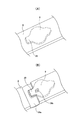
この様なエンジンの動弁機構に組み込むロッカーアームを低コストで得る為に、鋼板等の金属板に、打ち抜き加工、曲げ加工、増厚の為の据え込み加工等のプレス加工を施す事により造る事が考えられ、一部で実施されている。この様な板金製ロッカーアームに就いて記載した刊行物として、特許文献1〜5が存在する。図6は、このうちの特許文献5に記載された板金製ロッカーアームを示している。この板金製ロッカーアーム1は、互いにほぼ平行な1対の側壁部2、2と、これら両側壁部2、2の幅方向一端縁同士を連結する連結部3及び第二連結部4とを有する。又、これら両側壁部2、2の長さ方向中間部に1対の通孔5、5を、互いに同心に形成し、これら両通孔5、5に、カムと係合するローラを回転自在に支持する為の支持軸の両端部を支持自在としている。上記連結部3及び第二連結部4のうち、連結部3の片面には、弁体の基端部を突き当てる為の係合部6を、第二連結部4に、ラッシュアジャスタの先端部を突き当てる為の第二係合部7を、それぞれ形成している。
In order to obtain a rocker arm to be incorporated into such a valve mechanism of an engine at a low cost, it is made by subjecting a metal plate such as a steel plate to press working such as punching, bending and upsetting for thickening. Things are considered and some have been implemented.
上記係合部6と第二係合部7とのうち、係合部6は、上記連結部3の幅方向中間部の片面に、この連結部3の幅方向中間部を厚さ方向に塑性変形させる事により、この連結部3の他の部分よりも凹んだ凹溝状に形成している。これに対して、上記第二係合部7は、上記第二連結部4の中央部を厚さ方向に塑性変形させる事により、球状凹面として成る。
Of the
上述の様な板金製ロッカーアーム1の製造方法に就いては、前記特許文献5に記載された通りであるが、この特許文献5に記載された製造方法を実施する場合に一般的には、素材となる金属板から打ち抜いた素板を搬送しつつ所定の金型内に送り込み、加工後の中間素材を当該金型から取り出して別の金型内に送り込む、所謂トランスファー加工を採用する。但し、上記板金製ロッカーアーム1の場合には、加工途中の中間素材の形状も複雑になる為、上記素板及び中間素材の、各工程の金型内への送り込み作業及び取り出し作業が面倒で、これら各作業に時間を要し、生産効率を向上させる事が難しい。
About the manufacturing method of the
この様な事情に鑑みて、上記板金製ロッカーアーム1を、所謂順送加工により造る事が考えられる。図7は、この板金製ロッカーアーム1を、順送加工により造る状態を示している。この順送加工を行なう場合には、先ず、長さ方向(図7の左右方向)に送られる長尺な金属板8の一部を、図7の(B)位置でプレス加工により打ち抜く事により、所定の外形を有する素板9、9を、打ち抜き後のスケルトン10(打ち抜き残材)の柱部11の両側に形成する。尚、上記金属板8には、図7の(A)位置で、その一部を厚さ方向に押圧して金属材料を隣接部に流動させる加工を施す事により、上記図7の(A)位置に斜格子で示す部分の肉厚を増大させると共に、斜線で示す部分の肉厚を低下させている。
In view of such circumstances, it is conceivable to manufacture the sheet
上記図7の(B)位置で形成された上記各素板9、9は、続く(C)位置で幅方向(図7の左右方向)両側部分をほぼ直角に、同方向に折り曲げて断面形状を略U字形とする加工を施し、第一中間素材12、12とする。
これら両第一中間素材12、12には、図7の(D)位置で、中央部に鼓状の透孔13を形成する打ち抜き加工を施して、第二中間素材14、14とする。
これら両第二中間素材14、14には、図7の(E)位置で、上記透孔13の両側縁からこの透孔13の中央部に向けて突出した1対の凸円弧状部を図7の裏面方向に折り立てて、図7の手前に折り立てられた部分と面一にする(同一平面上に位置させる)扱き加工を施す。そして、互いに平行な1対の側壁部2、2を備えた、第三中間素材15、15とする。
これら両第三中間素材15、15には、図7の(F)位置で、上記両側壁部2、2の内側面(互いに対向する側面)を削ってこれら両内側面の寸法精度及び形状精度を向上させる、シェービング加工を施して、第四中間素材16、16とする。
これら両第四中間素材16、16には、図7の(G)位置で、これら両第四中間素材16、16を矯正用の金型で押圧して形状を整える整形加工を施して、第五中間素材17、17とする。
これら両第五中間素材17、17には、図7の(H)位置で、上記両側壁部2、2同士の間部分に設けられた連結部3及び第二連結部4に、係合部6及び第二係合部7を形成する塑性加工を施して、第六中間素材18、18とする。
これら両第六中間素材18、18には、図7の(I)位置で、上記両側壁部2、2の互いに整合する位置に通孔5、5を形成する打ち抜き加工を施して、第七中間素材19、19とする。
そして、最後に、上記両第七中間素材19、19を、図7の(J)位置で、前記スケルトン10の柱部11から(切断線α部分で)切り離して、前述の図6に示した様な板金製ロッカーアーム1を得る。
Each of the
Both the first
A pair of convex arcuate portions projecting from both side edges of the through-
These third
Both the fourth
Both the fifth
Both the sixth
Finally, both the seventh
上述の様な順送加工により上記板金製ロッカーアーム1を造る場合、上記スケルトン10を、送り方向に隣接する各素板9、9及び各中間素材12、14〜19のピッチP分ずつ間欠的に移動させれば、これら各素板9、9及び各中間素材12、14〜19の各金型内への送り込み作業及び取り出し作業を容易に行なえる。但し、上記順送加工の場合には、送り方向に隣接する各素板9、9及び各中間素材12、14〜19同士の間に加工用の金型を設置する必要がある。特に、上記第七中間素材19、19を得る為に、上記両通孔5、5を形成する為の金型は寸法が嵩む為、これら第七中間素材19、19と、隣接する第五中間素材18、18及び切り離される直前の板金製ロッカーアーム1、1との間には、十分な空間を設ける必要がある。
When the sheet
上記送り方向に隣接する各素板9、9及び各中間素材12、14〜19のピッチPは、最も大きな空間を必要とする部分に合わせて設定しなければならない為、このピッチPは相当に大きくしなければならない。そして、このピッチPを大きくすると、前記金属板8から打ち抜かれて廃材となる部分の割合が多くなり、材料の歩留低下に繋がり、上記板金製ロッカーアーム1、1の製造コスト上昇の原因になる為、好ましくない。
Since the pitch P of each of the
この点に就いて、図8〜9により説明する。先ず、図8は、図7の(B)位置と(C)位置との間に、素板9の一端部で係合部6(図6、7参照)となるべき部分の厚さ寸法(肉厚)を増大させる工程を設けた場合{図7の(A)位置で肉厚増大を行なわなかった場合}を示している。スケルトン10の柱部11の側縁から側方に突出する状態で形成された上記素板9の一端部で係合部6となるべき部分20を幅方向両側から挟む位置に、1対の押型21、21を有するダイセットを設置している。これら両押型21、21は、このダイセットを構成する基板の上面に、上記部分20に対する遠近動自在に支持している。又、このダイセットの一部で上記両押型21、21の反対側半部上方に位置する部分に、加圧ブロック22を、それぞれ昇降自在に設けている。そして、上記両押型21、21の上面で互いに反対側半部に形成した被押圧側傾斜面23、23と、上記両加圧ブロック22の下端部で互いに対向する側面に形成した押圧側傾斜面24とを、摺接させている。
This point will be described with reference to FIGS. First, FIG. 8 shows a thickness dimension of a portion (see FIGS. 6 and 7) between one end portion of the
上記部分20の肉厚を増大させる場合には、この部分20を上記両押型21、21の先端面同士の間に位置させた状態で、上記ダイセットの天板を下方に押圧する。そして、上記両加圧ブロック22を下方に押圧して、上記両押圧側傾斜面24と上記両被押圧側傾斜面23、23との係合に基づき、上記両押型21、21を互いに近づけ、これら両押型21、21の先端面同士の間で、上記部分20を幅方向両側から強く挟持する。この結果、この部分20の肉厚が増大される。尚、上述の様に、天板を下方に押圧する事により、カム機構(押圧側傾斜面と被押圧側傾斜面との係合部)を介して1対の押型等を互いに近づく方向に押圧するダイセットの構造は、プレス加工の技術分野で周知である為、詳しい図示並びに説明は省略する。
When the thickness of the
次に、図9は、図7の(I)位置で、(H)位置で得られた第六中間素材18を構成する1対の側壁部2、2に通孔5、5を、打ち抜きプレス加工により形成して、第七中間素材19とする状態を示している。この場合に使用するダイセットには、上述の図8に示した1対の押型21、21と同様の構造により互いに近づく方向に押圧される、1対の移動ブロック25、25を設けている。そして、これら両移動ブロック25、25の互いに対向する面に、それぞれ打ち抜きピン26、26を、互いに同心に固定している。上記両通孔5、5を形成する際には、上記両側壁部2、2同士の間に図示しない受型を挿入した状態で、上記両移動ブロック25、25を互いに近づけ、上記両打ち抜きピン26、26を、上記両側壁部2、2に突き通す。
Next, FIG. 9 is a punch press in which the through
この様な図8〜9により説明した通り、素板や中間素材にプレスによる塑性加工や打ち抜き加工を施す為には、これら素板や中間素材の側方に、プレス加工の為のダイセットの構成部品を配置する必要がある。特に、上記両側壁部2、2に通孔5、5を打ち抜き加工する為のダイセットの場合、互いに直列に結合乃至は配置された両移動ブロック25、25と両打ち抜きピン26、26とを第六中間素材18の両側方に、この第六中間素材18に対し遠近動自在に設ける。この為、上記両通孔5、5を形成すべき第六中間素材18の両側方には相当に大きなスペースが必要になる。前記送り方向に隣接する各素板9、9及び各中間素材12、14〜19のピッチPは、上記大きなスペースに合わせて設定しなければならず、前述した様な、材料の歩留低下に基づくコスト上昇の原因となる。
As described with reference to FIGS. 8 to 9, in order to perform plastic processing or punching by pressing a base plate or an intermediate material, a die set for press processing is provided on the side of the base plate or the intermediate material. Components need to be placed. In particular, in the case of a die set for punching the through
しかも、図8〜9を見れば明らかな通り、上記ダイセットと前記スケルトン10との上下位置を不動のまま、このスケルトン10を水平方向に送っても、上記素板や中間素材を上記所定位置にセットする事はできない。プレス加工の為のダイセットの所定位置に素板や中間素材をセットする為には、これらダイセットと素板や中間素材とを、水平方向だけでなく、上下方向にも、相当量相対変位させなければならない。この為、段取り作業が面倒になり、加工サイクル時間が長くなって、この面からも、板金製ロッカーアームの製造コストを高くする。
Moreover, as apparent from FIGS. 8 to 9, even if the
本発明は、上述の様な事情に鑑みて、各工程で、素板及び中間素材を金型内に送り込んだり、この金型から取り出す作業を容易に行なえ、しかも、金属板から打ち抜かれて廃材となる部分の割合を少なく抑える事で、板金製ロッカーアームのコストを抑えられる製造方法を実現すべく発明したものである。 In view of the circumstances as described above, the present invention can easily feed the base plate and the intermediate material into the mold and take them out of the mold in each process, and can be punched from the metal plate to be scrapped. The invention was invented to realize a manufacturing method capable of reducing the cost of the sheet metal rocker arm by suppressing the ratio of the portion to be reduced.
本発明の製造方法の対象となる板金製ロッカーアームは、1枚の金属板を打ち抜き成形する事により、所定の形状を有する素板を形成し、この素板にプレス加工に基づく曲げ加工を施す事により、互いにほぼ平行な1対の側壁部とこれら両側壁部の幅方向一端縁同士を連結する連結部とを形成して成る。そして、これら両側壁部の互いに整合する位置に形成した少なくとも1対の通孔と、上記連結部の一部に使用時に他の部材を突き当てる為に設けた、少なくとも1個の係合部とを備える。
そして、本発明の板金製ロッカーアームの製造方法は、上述の様な板金製ロッカーアームを造る際に、長さ方向に送られる長尺な上記金属板の一部を打ち抜く事により、一部がこの金属板と繋がったままである上記素板とする。次いで、この素板に対し、この金属板と繋がった状態のまま、複数の加工段階で順次必要な加工を施して、これら各加工段階に対応した中間素材とする。その後、上記金属板から切り離して、板金製ロッカーアームとする。
The sheet metal rocker arm which is the object of the manufacturing method of the present invention forms a base plate having a predetermined shape by punching and molding a single metal plate, and performs bending processing based on press processing on the base plate. Accordingly, a pair of side wall portions that are substantially parallel to each other and a connecting portion that connects one end edge in the width direction of both side wall portions are formed. And at least 1 pair of through-holes formed in the mutually aligned position of these both side wall parts, and at least 1 engaging part provided in order to abut another member at the time of use to a part of said connection part, Is provided.
And in the manufacturing method of the sheet metal rocker arm of the present invention, when making the sheet metal rocker arm as described above, a part of the long metal plate sent in the length direction is punched out, so that a part thereof The base plate remains connected to the metal plate. Next, the base plate is subjected to necessary processing in a plurality of processing stages while being connected to the metal plate, and an intermediate material corresponding to each processing stage is obtained. Then, it cuts from the said metal plate and makes it a sheet metal rocker arm.
特に、本発明の板金製ロッカーアームの製造方法に於いては、上記素板と上記各加工段階の中間素材とのそれぞれの長さ方向を、上記長尺な金属板の送り方向に一致させる。そして、上記素板及び上記各加工段階の中間素材のうちの上記連結部に対応する幅方向中央部分のみでこの送り方向に隣り合う素板と中間素材及び中間素材同士を連結して、これら素板及び中間素材を、この送り方向に関して互いに直列に配置する。又、この素板のうちで上記係合部となるべき部分を、上記長尺な金属板の送り方向に対して直角な方向である幅方向両側から、この素板の面方向に押圧する事により、この素板のうちで上記係合部となるべき部分の厚さ寸法を増大させる。 In particular, in the method for manufacturing a rocker arm made of sheet metal according to the present invention, the length directions of the base plate and the intermediate material at each processing stage are made to coincide with the feeding direction of the long metal plate. Then, only the central portion in the width direction corresponding to the connecting portion among the raw material and the intermediate material at each processing stage is connected to the raw material adjacent to the feed direction, the intermediate material, and the intermediate material, and these raw materials are connected. The plate and the intermediate material are arranged in series with respect to this feed direction. Further, a portion of the base plate that is to become the engaging portion is pressed in the surface direction of the base plate from both sides in the width direction that is a direction perpendicular to the feeding direction of the long metal plate. Thus, the thickness dimension of the portion of the base plate to be the engaging portion is increased.
上述の様に構成する本発明の板金製ロッカーアームの製造方法によれば、各工程で、素板及び中間素材を金型内に送り込んだり、この金型から取り出す作業を容易に行なえ、しかも、金属板から打ち抜かれて廃材となる部分の割合を少なく抑えられる。
即ち、上記素板及び中間素材を、長尺な金属板に繋がった状態のまま、この金属板の送り方向に移送する為、上記各工程での、上記素板及び中間素材の金型内への送り込みやこの金型からの取り出し作業を容易に行なえる。
又、上記素板及び中間素材のそれぞれの長さ方向を上記長尺な金属板の送り方向に一致させて、これら素板及び中間素材を、この送り方向に関して互いに直列に配置している為、隣り合う素板と中間素材との間、或いは隣り合う中間素材同士の間に金型を配置する必要がない。この為、金型を配置する為のスペース確保の為に、隣り合う素板と中間素材とのピッチ、及び、隣り合う中間素材同士のピッチを大きくする必要がない。そして、このピッチを小さく抑えられる分、上記金属板から打ち抜かれる廃材の割合を少なくして(材料の歩留を向上させて)、材料費の低減を図れる。
これらにより、板金製ロッカーアームのコストを抑えられる。
According to the method for manufacturing a sheet metal rocker arm of the present invention configured as described above, in each step, the base plate and the intermediate material can be easily fed into the mold or removed from the mold, The ratio of the parts that are punched out of the metal plate and become waste material can be reduced.
That is, in order to transfer the base plate and the intermediate material in the feeding direction of the metal plate while being connected to the long metal plate, the base plate and the intermediate material in the molds of the base plate and the intermediate material in the respective steps. Can be easily carried out and taken out from this mold.
In addition, since the length direction of each of the base plate and the intermediate material is made to coincide with the feed direction of the long metal plate, and the base plate and the intermediate material are arranged in series with respect to the feed direction, There is no need to dispose a mold between adjacent base plates and intermediate materials or between adjacent intermediate materials. For this reason, it is not necessary to increase the pitch between the adjacent base plate and the intermediate material and the pitch between the adjacent intermediate materials in order to secure a space for arranging the mold. And since this pitch can be kept small, the proportion of waste material punched from the metal plate can be reduced (improvement of material yield), and the material cost can be reduced.
As a result, the cost of the sheet metal rocker arm can be reduced.
しかも、上記素板のうちで係合部となるべき部分を、上記長尺な金属板の送り方向に対して直角な方向である幅方向両側から、この素板の面方向に押圧する事により、この素板のうちで上記係合部となるべき部分の厚さ寸法を増大させる為、厚さ寸法の均一な(低廉な)金属板を原材料として使用して、必要とされる強度が大きな、上記係合部となるべき部分の厚さ寸法を確保できる。この場合に、この部分以外の厚さ寸法が必要以上に大きくなる事はない。この為、軽量でしかも必要とする強度を十分に確保できる板金製ロッカーアームを、低コストで得られる。 In addition, by pressing a portion to be an engaging portion of the base plate from both sides in the width direction, which is a direction perpendicular to the feeding direction of the long metal plate, in the surface direction of the base plate. In order to increase the thickness dimension of the portion of the base plate to be the engaging portion, a metal plate having a uniform thickness dimension (low cost) is used as a raw material, and the required strength is high. The thickness dimension of the portion to be the engaging portion can be ensured. In this case, the thickness dimension other than this portion does not become larger than necessary. For this reason, a sheet metal rocker arm that is lightweight and can sufficiently secure the required strength can be obtained at low cost.
本発明を実施する場合に好ましくは、長尺な金属板を長さ方向に送りつつ、互いにほぼ平行な1対の側壁部を有する中間素材を形成する。そして、その後、上記金属板の送り方向に関して中間素材の側方に配置したパンチを上記両側壁部の一部に突き通す事により、これら両側壁部の一部に、互いに整合する1対の通孔を形成する。
この様に構成すれば、上記両通孔を有する上記両側壁を、低コストで造れ、しかも、これら両通孔の同心度を十分に確保できる。
When implementing this invention, Preferably, the intermediate raw material which has a pair of side wall part substantially parallel to each other is formed, sending a elongate metal plate to a length direction. Then, a pair of through-holes that are aligned with each other in a part of the both side wall parts by penetrating a part of the both side wall parts by punching a punch disposed on the side of the intermediate material with respect to the feeding direction of the metal plate. Form.
If comprised in this way, the said both side wall which has the said both through-holes can be manufactured at low cost, and the concentricity of these both through-holes can fully be ensured.
[本発明に関する参考例の第1例]
図1〜3は、本発明に関する参考例の第1例を示している。本参考例の場合、図1の左方に設置された図示しないアンコイラから送り出される長尺な帯状の金属板8に順次、塑性、打ち抜き等のプレス加工を施して、例えば前述の図6に示す様な板金製ロッカーアーム1を得る。加工の基本的手順に就いては、前述の図7に示した方法と同様である。即ち、上記金属板8の一部に、図1の(A)位置で、据え込み加工と呼ばれる肉厚調整加工を施す事により、斜格子部分の肉厚を増大させると同時に、斜線部分の肉厚を減少させる。このうちの肉厚を増大させる部分20は、上記板金製ロッカーアーム1として完成した状態で、係合部6を備えた連結部3となる。従って、上記金属板8として必要以上に厚さ寸法が大きなものを使用しなくても、上記連結部3の強度及び剛性を確保できる。
[First example of reference example of the present invention]
1-3 have shown the 1st example of the reference example regarding this invention . In the case of this reference example , a long strip-shaped
これに対して、肉厚を減少させる部分27a、27bは、上記板金製ロッカーアーム1を構成する1対の側壁部2、2の長さ方向両端部と上記連結部3及び第二連結部4の幅方向両端部との連続部となる。この様な連続部となる上記各部分27a、27bは、肉厚を減少させておく事により、後からの曲げ加工が容易に行なえる様にする。同時に、この曲げ加工に伴って生じる引っ張り応力に拘らず、亀裂等の損傷が発生しない様に、予め圧縮応力を付与しておく。
On the other hand, the
上述の様に、元の金属板8と板厚が異なる上記各部分20、27a、27bのうち、部分27a、27bの肉厚を減少させる作業は、単にこれら各部分27a、27bを両面側から、所望の厚さまで強く押圧すれば良い。押圧型の端面形状及び最接近時の距離を適切に規定すれば、上記各部分27a、27bの厚さ寸法及びこの厚さ寸法の分布を、所望通りに規制できる。この様な加工は、プレス加工の技術者であれば容易に実施できるので、図示は省略する。
As described above, the work of reducing the thickness of the
これに対して、上記部分20の厚さをプレス加工により増大させる方法は、種々考えられる。本参考例の場合には、図2に示す様に行なう。即ち、上記金属板8のうちで上記係合部6を備えた連結部3(図1)となるべき部分20の周囲部分28a、28bの厚さを、この金属板8の表裏方向に押圧する事により減少させる。そして、この周囲部分28a、28bに存在する金属材料を上記連結部3となるべき部分20に流動させ、上記金属板8のうちでこの連結部3となるべき部分20の厚さ寸法を増大させる。尚、上記両周囲部分28a、28bは、何れも後から除去する部分に形成する。即ち、図2に仮想線で描いた素板9の外側に位置する周囲部分28aは勿論、内側に位置する周囲部分28bに関しても、図1の(D)位置で形成する透孔13(後述)に整合する部分に形成して、薄肉とされた、上記周囲部分28a、28bが残らない様にする。
On the other hand, various methods for increasing the thickness of the
上記金属板8に関して、図1の(A)位置で上述の様な厚さ寸法を調整する為の加工を施した後、図1の(B)位置で、上記金属板8の幅方向両側部分をプレス加工により打ち抜く事により、所定の外形を有する素板9を、打ち抜き後のスケルトン10aの幅方向(図1の上下方向)中央部に形成する。この素板9と、上記金属板8及び後述する各中間素材12、14〜19とは、それぞれの幅方向中央部同士のみを、この金属板8の打ち抜き残部である幅狭部29、29により連結している。即ち、上記金属板8と、上記素板9と、上記各中間素材12、14〜19とは、これら素板9及び各中間素材12、14〜19の長さ方向に関する、上記金属板8の送り方向(図1の左右方向)に関して、互いに直列に、互いに等しいピッチPで結合されている。上記金属板8を前記板金製ロッカーアーム1に加工する際には、この金属板8と、上記素板9と、上記各中間素材12、14〜19とを、上記ピッチP分ずつ、間欠的に(加工の為の停止を繰り返しつつ)送る。
After the processing for adjusting the thickness dimension as described above at the position (A) in FIG. 1 with respect to the
上記図1の(B)位置で形成された上記素板9は、上記ピッチP分だけ後方(図1の右方)に送られて、図1の(C)位置で停止する。そして、この(C)位置で上記素板9に、幅方向(図1の上下方向、図6の左右方向)両側部分をほぼ直角に同方向に折り曲げて、断面形状を略U字形とする、曲げ加工を施して、第一中間素材12とする。この曲げ加工は、上記(C)位置に設置したダイセットに設けた受型と押型との間に上記素板9を位置させた状態で、このダイセットの押型をプレス加工機のラムにより受型に向けて押し付ける事により行なう。上記素板9乃至は上記第一中間素材12は、上記ダイセットの中間部に、これら素板9乃至は上記第一中間素材12の送り方向に存在する通路を送られるので、上記ダイセットの加工部への上記素板9の送り込み、及び、上記第一中間素材12の取り出しは、前記スケルトン10全体を、若干昇降させつつ長さ方向に送る事により、容易に行なえる。即ち、これら送り込み及び取り出しを行なう際に、上記素板9及び上記第一中間素材12を、上記ダイセット内で多少昇降させる必要はあるにしても、その昇降量は少なくて済む。従って、上記送り込み及び取り出し作業を容易に行なえ、段取りを含めて、加工時間(加工サイクル)を短くできる。
The
上記第一中間素材12には、図1の(D)位置で、中央部に鼓状の透孔13を形成する打ち抜き加工を施して、第二中間素材14とする。この様な透孔13を形成する為に、上記(D)位置に、打ち抜き用のパンチと受型とを備えたダイセットを設置しておく。このダイセットへの第一中間素材12の送り込み、このダイセットからの上記第二中間素材14の取り出しも、上記(C)位置での送り込み、取り出しと同様に、容易に行なえる。
The first
上記第二中間素材14には、図1の(E)位置で、互いに平行な1対の側壁部2、2を形成する為の扱き加工を施す。即ち、上記第二中間素材14に形成した透孔13の両側縁からこの透孔13の中央部に向けて突出した1対の凸円弧状部30、30を図1の裏面方向に(紙面と直角になるまで)折り立てて、図1の手前に折り立てられた主部分31、31と面一にする(同一平面上に位置させる)。そして、互いに平行な1対の側壁部2、2を備えた、第三中間素材15とする。この様な扱き加工を行なう為に、上記(E)位置に、上記透孔13に突き通す扱き用のパンチと、このパンチにより塑性変形させられる上記両凸円弧状部30、30を受け入れる受型とを備えたダイセットを設置しておく。このダイセットへの上記第二中間素材14の送り込み、このダイセットからの上記第三中間素材15の取り出しも、上記(C)(D)位置での送り込み、取り出しと同様に、容易に行なえる。
The second
上記第三中間素材15には、図1の(F)位置で、上記両側壁部2、2の内側面(互いに対向する側面)を削ってこれら両内側面の寸法精度及び形状精度を向上させる、シェービング加工を施し、第四中間素材16とする。この様なシェービング加工を行なう為に、上記(F)位置に、上記両側壁部2、2の内側面を削る為のシェービングパンチと、これら両側壁2、2を支承すると共にこのシェービングパンチの先端部を受け入れる為の受型とを備えたダイセットを設置しておく。このダイセットへの上記第三中間素材15の送り込み、このダイセットからの上記第四中間素材16の取り出しも、上記(C)〜(E)位置での送り込み、取り出しと同様に、容易に行なえる。
In the third
上記第四中間素材16には、図1の(G)位置で整形加工を施して、第五中間素材17とする。この整形加工を施す為に、この(G)位置に、押型と受型とから成る矯正用の金型を備えた、ダイセットを設置しておく。上記第四中間素材16を上記第五中間素材17とするには、この第四中間素材16を上記押型と受型との間で押圧して、形状を整える。上記ダイセットへの上記第四中間素材16の送り込み、このダイセットからの上記第五中間素材17の取り出しも、上記(C)〜(F)位置での送り込み、取り出しと同様に、容易に行なえる。
The fourth
上記第五中間素材17には、図1の(H)位置で、上記両側壁部2、2同士の間部分に設けられた連結部3及び第二連結部4に、係合部6及び第二係合部7を形成する塑性加工を施して、第六中間素材18とする。これら両係合部6、7を形成する為、上記(H)位置に、1対の押部を備えた押型と、1対の受部を備えた受型とから成る、塑性加工用の金型を備えた、ダイセットを設置しておく。上記第五中間素材17を上記第六中間素材18とするには、この第五中間素材17のうちの連結部3及び第二連結部4を上記押型と受型との間で押圧して、これら両連結部3、4に上記両係合部6、7を形成する。上記ダイセットへの上記第五中間素材17の送り込み、このダイセットからの上記第六中間素材18の取り出しも、上記(C)〜(G)位置での送り込み、取り出しと同様に、容易に行なえる。
In the fifth
上記第六中間素材18には、図1の(I)位置で、上記両側壁部2、2の互いに整合する位置に通孔5、5を形成する打ち抜き加工を施して、第七中間素材19とする。この場合に使用するダイセットの構造は、前述の図8に示したものと同様であるが、設置方向及び設置位置が、この図8とは異なる。即ち、本参考例の場合には、図3に示す様に、1対の移動ブロック25、25を、前記スケルトン10aを幅方向両側から挟む位置に設置している。そして、これら両移動ブロック25、25の互いに対向する面に1対の打ち抜きピン26、26を、互いに同心に固定している。上記両通孔5、5を形成する際には、上記両側壁部2、2同士の間に図示しない受型を挿入した状態で、上記両移動ブロック25、25を互いに近づけ、上記両打ち抜きピン26、26を、上記両側壁部2、2に突き通す。
The sixth
前述した通り、上記両移動ブロック25、25及び上記両打ち抜きピン26、26を備えたダイセットを設置する為に、上記両通孔5、5を形成すべき第六中間素材18の両側方には大きなスペースが必要になる。これに対して本参考例の場合には、この第六中間素材18を含む、上記スケルトン10aの側方には、元々十分なスペースが存在する。そして、上記ダイセットを設置する為に、送り方向に隣り合う素板9、各中間素材12、14〜19のピッチを大きくする必要はない。この為、上記両通孔5、5を形成する為の構造に起因して、前記金属板8の歩留が悪化する事はない。
上記ダイセットへの上記第六中間素材18の送り込み、このダイセットからの上記第七中間素材19の取り出しも、上記(C)〜(H)位置での送り込み、取り出しと同様に、容易に行なえる。
そして、最後に、上記第七中間素材19を、図1の(J)位置で、前記スケルトン10aの幅狭部29から(切断線α部分で)切り離して、前述の図6に示した様な板金製ロッカーアーム1を得る。
As described above, in order to install a die set having both the moving
The feeding of the sixth
Finally, the seventh
[本発明の実施の形態の1例]
図4は、本発明の実施の形態の1例を示している。本例の場合には、係合部6を備えた連結部3(図6参照)となるべき部分20の厚さ寸法を増大させる加工を、図1の(B)位置と(C)位置との間位置で、素板9に対して施す様にしている。この為に、この間位置に、前述の図8に示した構造と同様に、1対の押型21、21を有するダイセットを設置している。上記部分20の肉厚を増大させる場合には、この部分20を上記両押型21、21の先端面同士の間に位置させた状態で、上記ダイセットの天板を下方に押圧する。そして、両加圧ブロック22を下方に押圧して、両押圧側傾斜面24と両被押圧側傾斜面23、23との係合に基づき、上記両押型21、21を互いに近づけ、これら両押型21、21の先端面同士の間で、上記部分20を送り方向に対して直角な方向である幅方向両側から強く挟持する。この結果、この部分20の肉厚が増大される。
この部分20の肉厚を増大させる方法を異ならせる以外の点に就いては、上述の参考例の第1例の場合と同様である。
[One Example of Embodiment of the Present Invention]
FIG. 4 shows an example of an embodiment of the present invention. In the case of this example, the processing for increasing the thickness dimension of the
The points other than the method of increasing the thickness of the
[本発明に関する参考例の第2例]
図5は、本発明に関する参考例の第2例を示している。本参考例の場合には、先ず、(A)に示した素板9のうちで係合部6を備えた連結部3(図6参照)となるべき部分20に塑性加工を施す事により、(B)に示す様に、長尺な金属板8(図1参照)の送り方向と直角方向である幅方向に関するこの部分20の断面形状を湾曲させる。その後、この部分20の幅寸法W20がこの湾曲した状態よりも大きくなる事を防止した状態でこの部分20を、上記素板9の表裏両面側から押圧して平坦にする。そして、(C)に示す様に、この素板9のうちで上記係合部6を備えた連結部3となるべき部分20の厚さ寸法T20を増大させる。
この部分20の肉厚を増大させる方法を異ならせる以外の点に就いては、前述の参考例の第1例の場合と同様である。
[Second Example of Reference Example of the Present Invention]
FIG. 5 shows a second example of the reference example related to the present invention . In the case of this reference example , first, by performing plastic working on the
The points other than the method of increasing the thickness of the
図示の例では、スケルトンの送り方向に隣接する素板乃至は中間素材の種類を互いに異ならせると共に、このスケルトンを1ピッチ分ずつ間欠的に送る事により、この送り方向後端部で、完成した板金製ロッカーアームを1個ずつ取り出す、所謂1個取りの場合に就いて説明した。これに対して、本発明を実施する場合に、スケルトンの送り方向に関して隣接する位置に同種の素板乃至は中間素材を配置すると共に、このスケルトンを2ピッチ分ずつ間欠的に送る事により、この送り方向後端部で、完成した板金製ロッカーアームを2個ずつ取り出す、所謂2個取りを行なう事もできる。この様な2個取りを行なえば、板金製ロッカーアームの加工能率の向上を図れる。 In the example shown in the drawing, the types of base plates or intermediate materials adjacent to each other in the feeding direction of the skeleton are made different from each other and the skeleton is intermittently sent by one pitch at a time, thereby completing the rear end in the feeding direction. The case where the sheet metal rocker arms are taken out one by one, that is, the so-called single picking has been described. On the other hand, when the present invention is carried out, the same kind of base plate or intermediate material is arranged at an adjacent position with respect to the feeding direction of the skeleton, and this skeleton is intermittently sent by two pitches. At the rear end in the feed direction, so-called double cutting can be performed in which two completed sheet metal rocker arms are taken out. If such two pieces are taken, the processing efficiency of the rocker arm made of sheet metal can be improved.
又、図示の例は、板金製ロッカーアームの加工手順の1例であり、本発明を実施する場合の加工手順は、図示の例と異なっても良い。例えば、鼓状の透孔を形成する工程は、素板の打ち抜き加工と同時に、或いはこの打ち抜き加工に続く工程で行なっても良い。又、係合部と第二係合部との加工を同時に行なわず、別工程で行なっても良い。更には、板金製ロッカーアームの構造に就いても、図示の様に、長さ方向両端部に1対の係合部を、中間部にローラを支持する為の1対の側壁部を、それぞれ有するものに限定されない。例えば、長さ方向一端部にローラを、長さ方向中間部に枢軸を、それぞれ支持する為の1対の側壁部を設け、長さ方向他端部に吸気弁或いは排気弁の基端面を突き当てる為の係合部を有する連結部を備えた板金製ロッカーアームの製造に関して、本発明を実施する事もできる。 The illustrated example is an example of the processing procedure for the rocker arm made of sheet metal, and the processing procedure in carrying out the present invention may be different from the illustrated example. For example, the step of forming the drum-shaped through hole may be performed simultaneously with the blanking process of the base plate or in a process subsequent to the punching process. Further, the processing of the engaging portion and the second engaging portion may not be performed at the same time but may be performed in separate steps . Furthermore , even in the structure of the rocker arm made of sheet metal, as shown in the figure, a pair of engaging portions are provided at both ends in the length direction, and a pair of side walls for supporting the roller at the intermediate portion. It is not limited to what it has. For example, a pair of side walls for supporting a roller at one end in the length direction and a pivot at the middle in the length direction are provided, and the base end surface of the intake valve or exhaust valve is projected at the other end in the length direction. The present invention can also be implemented with respect to the manufacture of a sheet metal rocker arm provided with a connecting portion having an engaging portion for contact.
1 板金製ロッカーアーム
2 側壁部
3 連結部
4 第二連結部
5 通孔
6 係合部
7 第二係合部
8 金属板
9 素板
10、10a スケルトン
11 柱部
12 第一中間素材
13 透孔
14 第二中間素材
15 第三中間素材
16 第四中間素材
17 第五中間素材
18 第六中間素材
19 第七中間素材
20 部分
21 押型
22 加圧ブロック
23 被押圧側傾斜面
24 押圧側傾斜面
25 移動ブロック
26 打ち抜きピン
27a、27b 部分
28a、28b 周囲部分
29 幅狭部
30 凸円弧状部
31 主部分
DESCRIPTION OF
Claims (1)
Priority Applications (1)
| Application Number | Priority Date | Filing Date | Title |
|---|---|---|---|
| JP2005067701A JP4539381B2 (en) | 2005-03-10 | 2005-03-10 | Sheet metal rocker arm manufacturing method |
Applications Claiming Priority (1)
| Application Number | Priority Date | Filing Date | Title |
|---|---|---|---|
| JP2005067701A JP4539381B2 (en) | 2005-03-10 | 2005-03-10 | Sheet metal rocker arm manufacturing method |
Related Child Applications (1)
| Application Number | Title | Priority Date | Filing Date |
|---|---|---|---|
| JP2009238145A Division JP4858592B2 (en) | 2009-10-15 | 2009-10-15 | Sheet metal rocker arm manufacturing method |
Publications (3)
| Publication Number | Publication Date |
|---|---|
| JP2006250044A JP2006250044A (en) | 2006-09-21 |
| JP2006250044A5 JP2006250044A5 (en) | 2007-12-20 |
| JP4539381B2 true JP4539381B2 (en) | 2010-09-08 |
Family
ID=37090798
Family Applications (1)
| Application Number | Title | Priority Date | Filing Date |
|---|---|---|---|
| JP2005067701A Expired - Fee Related JP4539381B2 (en) | 2005-03-10 | 2005-03-10 | Sheet metal rocker arm manufacturing method |
Country Status (1)
| Country | Link |
|---|---|
| JP (1) | JP4539381B2 (en) |
Cited By (1)
| Publication number | Priority date | Publication date | Assignee | Title |
|---|---|---|---|---|
| CN103600005A (en) * | 2013-10-09 | 2014-02-26 | 杭州新坐标科技股份有限公司 | Machine-shaping method of rocker arm frame |
Families Citing this family (2)
| Publication number | Priority date | Publication date | Assignee | Title |
|---|---|---|---|---|
| JP5345075B2 (en) * | 2010-01-08 | 2013-11-20 | 株式会社オティックス | Rocker arm manufacturing method |
| JP6319044B2 (en) * | 2014-10-28 | 2018-05-09 | トヨタ車体株式会社 | Press mold |
Citations (6)
| Publication number | Priority date | Publication date | Assignee | Title |
|---|---|---|---|---|
| JPH11210417A (en) * | 1998-01-21 | 1999-08-03 | Nakanishi Metal Works Co Ltd | Manufacture of rocker arm |
| JP2000110522A (en) * | 1998-08-07 | 2000-04-18 | Nsk Ltd | Sheet metal-made rocker arm |
| JP2001047180A (en) * | 1999-05-31 | 2001-02-20 | Koyo Seiko Co Ltd | Rocker arm, and manufacture of rocker arm body |
| JP2001289011A (en) * | 2001-04-19 | 2001-10-19 | Nsk Ltd | Method of manufacturing plate rocker arm |
| JP2005002810A (en) * | 2003-06-10 | 2005-01-06 | Fuji Heavy Ind Ltd | Manufacturing method of metal plate-made rocker arm |
| WO2005021183A1 (en) * | 2003-08-27 | 2005-03-10 | Gen Tek Technologies Marketing, Inc. | A method and system for forming a cam-engaged rocker arm |
-
2005
- 2005-03-10 JP JP2005067701A patent/JP4539381B2/en not_active Expired - Fee Related
Patent Citations (6)
| Publication number | Priority date | Publication date | Assignee | Title |
|---|---|---|---|---|
| JPH11210417A (en) * | 1998-01-21 | 1999-08-03 | Nakanishi Metal Works Co Ltd | Manufacture of rocker arm |
| JP2000110522A (en) * | 1998-08-07 | 2000-04-18 | Nsk Ltd | Sheet metal-made rocker arm |
| JP2001047180A (en) * | 1999-05-31 | 2001-02-20 | Koyo Seiko Co Ltd | Rocker arm, and manufacture of rocker arm body |
| JP2001289011A (en) * | 2001-04-19 | 2001-10-19 | Nsk Ltd | Method of manufacturing plate rocker arm |
| JP2005002810A (en) * | 2003-06-10 | 2005-01-06 | Fuji Heavy Ind Ltd | Manufacturing method of metal plate-made rocker arm |
| WO2005021183A1 (en) * | 2003-08-27 | 2005-03-10 | Gen Tek Technologies Marketing, Inc. | A method and system for forming a cam-engaged rocker arm |
Cited By (1)
| Publication number | Priority date | Publication date | Assignee | Title |
|---|---|---|---|---|
| CN103600005A (en) * | 2013-10-09 | 2014-02-26 | 杭州新坐标科技股份有限公司 | Machine-shaping method of rocker arm frame |
Also Published As
| Publication number | Publication date |
|---|---|
| JP2006250044A (en) | 2006-09-21 |
Similar Documents
| Publication | Publication Date | Title |
|---|---|---|
| JP4685548B2 (en) | Method for manufacturing rocker arm | |
| US20060143912A1 (en) | Method for manufacturing rocker arm | |
| US10124398B2 (en) | Method for producing a forged crankshaft | |
| JP4235196B2 (en) | Method for manufacturing rocker arm | |
| US10350671B2 (en) | Method for producing a forged crankshaft | |
| WO2002085554A1 (en) | Metal plate rocker arm and method of manufacturing the metal plate rocker arm | |
| EP2394754A1 (en) | Method and apparatus for producing crank shaft | |
| WO2015075924A1 (en) | Production method for forged crank shaft | |
| WO2016159246A1 (en) | Method for manufacturing forged crankshaft | |
| JP4539381B2 (en) | Sheet metal rocker arm manufacturing method | |
| JP2004358538A (en) | Rocker arm manufacturing method | |
| JP4858592B2 (en) | Sheet metal rocker arm manufacturing method | |
| JP3497373B2 (en) | Rocker arm and method of manufacturing the same | |
| JP2009520602A (en) | Method and embossing apparatus for manufacturing rocker pins | |
| JP4127408B2 (en) | Sheet metal rocker arm manufacturing method | |
| JP2007307581A (en) | Multi-stage former | |
| JP2005002810A (en) | Manufacturing method of metal plate-made rocker arm | |
| JP6380670B2 (en) | Forging crankshaft manufacturing equipment | |
| JP4155995B2 (en) | Sheet metal rocker arm manufacturing method | |
| JP6555393B2 (en) | Manufacturing method of forged crankshaft | |
| JP4819748B2 (en) | Method for manufacturing rocker arm | |
| JP2005000923A (en) | Method for manufacturing rocker arm formed of sheet metal | |
| JP2005002809A (en) | Manufacturing method of metal plate-made rocker arm | |
| JP6550919B2 (en) | Forging crankshaft manufacturing equipment | |
| JP6387721B2 (en) | Manufacturing method of forged crankshaft |
Legal Events
| Date | Code | Title | Description |
|---|---|---|---|
| RD04 | Notification of resignation of power of attorney |
Free format text: JAPANESE INTERMEDIATE CODE: A7424 Effective date: 20070507 |
|
| A521 | Written amendment |
Free format text: JAPANESE INTERMEDIATE CODE: A523 Effective date: 20071031 |
|
| A621 | Written request for application examination |
Free format text: JAPANESE INTERMEDIATE CODE: A621 Effective date: 20071031 |
|
| A977 | Report on retrieval |
Free format text: JAPANESE INTERMEDIATE CODE: A971007 Effective date: 20090813 |
|
| A131 | Notification of reasons for refusal |
Free format text: JAPANESE INTERMEDIATE CODE: A131 Effective date: 20090818 |
|
| A521 | Written amendment |
Free format text: JAPANESE INTERMEDIATE CODE: A523 Effective date: 20091015 |
|
| A131 | Notification of reasons for refusal |
Free format text: JAPANESE INTERMEDIATE CODE: A131 Effective date: 20100427 |
|
| A521 | Written amendment |
Free format text: JAPANESE INTERMEDIATE CODE: A523 Effective date: 20100511 |
|
| TRDD | Decision of grant or rejection written | ||
| A01 | Written decision to grant a patent or to grant a registration (utility model) |
Free format text: JAPANESE INTERMEDIATE CODE: A01 Effective date: 20100601 |
|
| A01 | Written decision to grant a patent or to grant a registration (utility model) |
Free format text: JAPANESE INTERMEDIATE CODE: A01 |
|
| A61 | First payment of annual fees (during grant procedure) |
Free format text: JAPANESE INTERMEDIATE CODE: A61 Effective date: 20100614 |
|
| R150 | Certificate of patent or registration of utility model |
Ref document number: 4539381 Country of ref document: JP Free format text: JAPANESE INTERMEDIATE CODE: R150 Free format text: JAPANESE INTERMEDIATE CODE: R150 |
|
| FPAY | Renewal fee payment (event date is renewal date of database) |
Free format text: PAYMENT UNTIL: 20130702 Year of fee payment: 3 |
|
| LAPS | Cancellation because of no payment of annual fees |