JP2004347209A - Outdoor unit, air conditioner using it, and heat pump type water heater - Google Patents
Outdoor unit, air conditioner using it, and heat pump type water heater Download PDFInfo
- Publication number
- JP2004347209A JP2004347209A JP2003143390A JP2003143390A JP2004347209A JP 2004347209 A JP2004347209 A JP 2004347209A JP 2003143390 A JP2003143390 A JP 2003143390A JP 2003143390 A JP2003143390 A JP 2003143390A JP 2004347209 A JP2004347209 A JP 2004347209A
- Authority
- JP
- Japan
- Prior art keywords
- outdoor unit
- blower fan
- brake pad
- casing
- fan
- Prior art date
- Legal status (The legal status is an assumption and is not a legal conclusion. Google has not performed a legal analysis and makes no representation as to the accuracy of the status listed.)
- Pending
Links
Images

Abstract
Description
【0001】
【発明の属する技術分野】
本発明は、冷凍サイクルが内蔵されている室外ユニットに関し、室外ユニットを用いた家庭用空気調和機又はヒートポンプ式給湯機に適用される。
【0002】
【従来の技術】
従来、家庭用空気調和機やヒートポンプ式給湯機の室外ユニットは、熱交換器と、熱交換器の風下側に配置された送風ファンとを内部に収納するケーシングを備えている。これにより、送風ファンをモータで駆動回転させることにより、熱交換器等の冷媒中の熱と熱交換した空気をケーシングの正面の吹出口から室外ユニットの外に排出する(例えば、特許文献1参照。)。
【0003】
【特許文献1】
特開2002−195610号公報
【0004】
ところで、室外ユニットは屋外に設置されているので、室外ユニットの吹出口を通って送風ファンに当たることにより、送風ファンが通常の駆動回転方向と逆方向に回転してしまうことがある。この送風ファンの逆回転は、例えば台風などの風が強い場合には、送風ファンの回転数が非常に高くなり、送風ファンの羽根が破損してしまうという問題や、送風ファンがインバータ駆動式であるならば送風ファンの逆回転に伴うモータの逆回転によって発生する逆起電圧によってインバータ等の電気部品が破壊されてしまうという問題がある。
【0005】
【発明が解決しようとする課題】
上記問題点に鑑み、本発明の目的は、逆風による送風ファンの破損を防止できる室外ユニットを提供することである。
【0006】
【課題を解決するための手段】
本発明の請求項1に係る室外ユニットによれば、吹出口を正面において有するケーシングと、ケーシング内の後側に配置された空気熱交換器と、ケーシング内の前側に配置された送風ファンとを備え、空気熱交換器で熱交換された空気を送風ファンにより吹出口を通して吹き出す室外ユニットにおいて、送風ファンにブレーキパッドが接続されており、送風ファンの回転数が予め定めた閾値以上の場合にブレーキパッドが室外ユニットに設けられた当接部に接触する。これにより、送風ファンの回転数が予め定めた回転数以上の場合において送風ファンに設けたブレーキパッドが室外ユニットに設けた当接部に接触することで送風ファンを制動することができ、逆風による送風ファンの破損を防止することができる。
【0007】
請求項2に係る室外ユニットによれば、室外ユニットの当接部は、送風ファンの半径方向においてブレーキパッドよりも外側に配置されており、送風ファンの回転数が予め定めた閾値以上の場合にブレーキパッドが当接部に接触するように、ブレーキパッドがばねによって送風ファンの半径方向内側に付勢されて送風ファンに接続されている。これにより、送風ファンの回転数が予め定めた回転数以上の場合において、ブレーキパッドに半径方向外側に作用する遠心力が半径方向内側に作用するばねの付勢力を上回ることにより、ブレーキパッドが当接部に接触するように構成されている、すなわち、送風ファンのブレーキ作用が機械的な機構で実現されるので、送風ファンのブレーキ作用の確実性が保証される。
【0008】
請求項3に係る室外ユニットによれば、室外ユニットの当接部は、ケーシングの正面を構成するファンガードに設けられている。これにより、ファンガードと当接部を共用することにより、製造コストを低減することができる。
【0009】
請求項4に係る室外ユニットによれば、予め定めた閾値は、送風ファンが破損する可能性のある回転数である。これにより、送風ファンが破損しない回転数未満に送風ファンの回転数を確実に保つことができ、確実に送風ファンの破損を防止することができる。
【0010】
請求項5に係る家庭用空気調和機によれば、家庭用空気調和機に上記室外ユニットが用いられている。このように、室外ユニットが家庭用空気調和機に適用されうる。
【0011】
請求項6に係るヒートポンプ式給湯機によれば、ヒートポンプ式給湯機に上記室外ユニットが用いられている。このように、室外ユニットがヒートポンプ式給湯機に適用されうる。
【0012】
【発明の実施の形態】
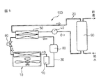
以下、本発明の実施例について添付図面を参照して詳細に説明する。図1は本発明の室外ユニットを用いたヒートポンプ式給湯機100の模式図である。ヒートポンプ式給湯機100の回路は、水回路20と冷媒回路30からなる。
【0013】
水回路20の構成について説明する。水回路20は、例えば水道水からなる水を運搬する回路であり、貯湯タンク90と、循環ポンプ40と、水と冷媒回路30中の冷媒と熱交換するための水冷媒熱交換器50とが配置されている。水回路20の流れについて便宜的に貯湯タンク90から説明すると、最初に、貯湯タンク90を介して給水される室温の水は、循環ポンプ40によって水冷媒熱交換器50まで搬送され、ここで高温の冷媒との熱交換により例えば90°などの高温に加熱される。このように加熱された湯は、貯湯タンクに貯蔵されるか、給湯又は風呂の用途のためにさらに下流へ流される。
【0014】
次に冷媒回路30の構成について説明する。冷媒回路30は、例えばフロンからなる冷媒を循環させる回路であり、コンプレッサ80と、冷媒と水回路中20の水とを熱交換するための水冷媒熱交換器50と、減圧装置60と、室外ユニット10の空気熱交換器(蒸発器)と、アキュムレータ70とが配置されている。なお、コンプレッサ80は、コンバータ(図示せず)によって外部電源の交流電圧から変換された直流電圧を供給されて駆動される。冷媒回路30の流れについて便宜的にコンプレッサ80から説明すると、最初、アキュムレータ70から冷媒は、コンプレッサ80により、冷媒は高温高圧の気体となる。この高温高圧の気体状の冷媒は、水冷媒熱交換器50において室温の水との熱交換により冷却されて液化する。この冷媒は、減圧装置60で膨張させられて低温低圧状態の液体となる。次に、冷媒は、室外ユニット10の空気熱交換器で室温の空気と熱交換される。これにより、冷媒は加熱されて膨張して霧状に気化する。ここで、送風ファン1により空気熱交換器に送風することによって、冷媒と空気の熱交換を促進する。最後に、空気熱交換器で気化した冷媒は、アキュムレータ70に貯蔵され、気体と液体に分離される。気体状の冷媒がコンプレッサ80へ供給される。なお、本実施例では、減圧装置60として、作動状態により冷媒流量を制御できる電気式エキスパンションバルブを採用する。
【0015】
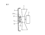
次に室外ユニット10の送風ファン1について説明する。図2は本発明の第一実施例のファン回転抑制機構の側断面図である。室外ユニット10は、ケーシングの内部において前側から後側に向けて、図2における左側に示すケーシングの正面の一部を構成するファンガード3と、送風ファン1と、送風ファン1を回転駆動するモータ2と、空気熱交換器(図示せず)とが配置されている。なお、ファンガード3は、例えば網状で無数の吹出口を有する。このような構成により、電子制御装置(図示せず)からの指令に応答してモータ2に起動電力を与えて送風ファン1を約600〜1000rpm程度の速度で回転させることにより、空気熱交換器からファンガード3の吹出口を通して室外ユニット10の外へ流れる空気流を形成し、空気熱交換器における冷媒と空気の熱交換を促進する。
【0016】
この送風ファン1は、ファンガード3の吹出口を通して逆風を受けて回転駆動方向と逆方向に回転することがある。この回転数は、例えば台風などの風が強い時には約2000rpmの高回転(異常回転と呼ぶ)となり、送風ファン1が破損してしまう可能性がある。そこで、本発明では、以下に説明するように、送風ファン1の回転数を抑制するためのファン回転抑制機構を提供する。
【0017】
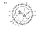
本発明のファン回転抑制機構について図2及び3を参照しつつ説明する。図3は第一実施例のファン回転抑制機構の正面図である。ファン回転抑制機構は、送風ファン1と接続されたブレーキパッド14と、ブレーキパッド14が当接する、室外ユニット1に設けられた当接部31aで構成される。ブレーキパッド14は、送風ファン1のハブ11に取り付けられたプレート12上において、プレート12に固定されたピン16回りに回転可能に留められている。また、ブレーキパッド14は、中央に配置されたピン15に一端が接続されているばね13の他端と接続されており、送風ファン1の半径方向内側に付勢されている。一方、当接部31aは、ブレーキパッド14の半径方向外側において、ブレーキパッド14を囲うように、ファンガード3の内面からケーシングの内側に向けて延びている筒状部材31の内面である。この当接部31aは、ブレーキパッド14が半径方向外側に変位する時にブレーキパッド14と当接するように位置している。
【0018】
このような構成により、送風ファン1の回転数が増大すると、ブレーキパッド14に半径方向外側に作用する遠心力が、半径方向内側に作用するばね13の付勢力を上回り、図4に示すように、ブレーキパッド14がファンガード3の当接部31aに接触し、送風ファン1の回転を制動することができる。なお、このブレーキパッド14が当接部31aに接触する時の送風ファン1の回転数(閾値と呼ぶ)は、ブレーキパッド14とばね13を設定することによって予め定めることができる。例えば、送風ファン1が破損する可能性のある回転数を閾値として予め定めることにより、送風ファン1の回転数を送風ファン1の破損しない回転数に確実に保つことができる。
【0019】
ブレーキパッド14の数は、本実施例では2つであり、二つのブレーキパッド14は、送風ファン1の軸線に対して回転対称にプレート12上に配置されている。当然、ブレーキパッド14が送風ファン1の中心軸線に対して回転対称にプレート12上に配置されているならば、ブレーキパッド14は三つ以上でもよい。
【0020】
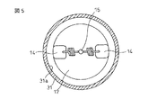
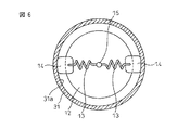
次に本発明の第二実施例のファン回転抑制機構について説明する。図5は第二実施例のファン回転抑制機構の正面図である。ファン回転抑制機構は、第一実施例と同様であるが、ブレーキパッド14をプレート12に留めるピン16を省略した構成である。これにより、製造コストを低減することができるという利点がある。
【0021】
本発明の実施例では、本発明の室外ユニットをヒートポンプ式給湯機に適用した例で説明したが、当然、本発明の室外ユニットはヒートポンプ式給湯機に代わって家庭用空気調和機を適用してもよい。
【図面の簡単な説明】
【図1】本発明の室外ユニットを用いたヒートポンプ式給湯機の模式図である。
【図2】本発明の第一実施例のファン回転抑制機構の側断面図である。
【図3】本発明の第一実施例のファン回転抑制機構の正面図である。
【図4】本発明の第一実施例のファン回転抑制機構の送風ファン制動時の正面図である。
【図5】本発明の第二実施例のファン回転抑制機構の正面図である。
【図6】本発明の第二実施例のファン回転抑制機構の送風ファン制動時の正面図である。
【符号の説明】
1…送風ファン
10…室外ユニット
14…ブレーキパッド
31a…当接部[0001]
TECHNICAL FIELD OF THE INVENTION
The present invention relates to an outdoor unit having a built-in refrigeration cycle, and is applied to a home air conditioner or a heat pump water heater using the outdoor unit.
[0002]
[Prior art]
2. Description of the Related Art Conventionally, an outdoor unit of a home air conditioner or a heat pump water heater has a casing in which a heat exchanger and a blower fan arranged downstream of the heat exchanger are housed. Thus, the air that has exchanged heat with the heat in the refrigerant, such as a heat exchanger, is discharged from the outlet at the front of the casing to the outside of the outdoor unit by driving and rotating the blower fan by the motor (for example, see Patent Document 1). .).
[0003]
[Patent Document 1]
JP-A-2002-195610
By the way, since the outdoor unit is installed outdoors, when the outdoor unit hits the blower fan through the outlet of the outdoor unit, the blower fan may rotate in a direction opposite to the normal driving rotation direction. The reverse rotation of the blower fan is, for example, when the wind such as a typhoon is strong, the rotation speed of the blower fan becomes extremely high, and the blades of the blower fan are damaged. If there is, there is a problem that an electric component such as an inverter is destroyed by a back electromotive voltage generated by the reverse rotation of the motor accompanying the reverse rotation of the blower fan.
[0005]
[Problems to be solved by the invention]
In view of the above problems, an object of the present invention is to provide an outdoor unit that can prevent a blower fan from being damaged by a headwind.
[0006]
[Means for Solving the Problems]
ADVANTAGE OF THE INVENTION According to the outdoor unit which concerns on
[0007]
According to the outdoor unit according to
[0008]
According to the outdoor unit of the third aspect, the contact portion of the outdoor unit is provided on the fan guard that forms the front of the casing. Thereby, the manufacturing cost can be reduced by sharing the contact part with the fan guard.
[0009]
According to the outdoor unit of the fourth aspect, the predetermined threshold value is a rotation speed at which the blower fan may be damaged. Thus, the rotation speed of the blower fan can be reliably maintained below the rotation speed at which the blower fan is not damaged, and the breakage of the blower fan can be reliably prevented.
[0010]
According to the domestic air conditioner according to claim 5, the outdoor unit is used in a domestic air conditioner. Thus, the outdoor unit can be applied to a home air conditioner.
[0011]
According to the heat pump water heater according to claim 6, the outdoor unit is used in the heat pump water heater. Thus, the outdoor unit can be applied to a heat pump water heater.
[0012]
BEST MODE FOR CARRYING OUT THE INVENTION
Hereinafter, embodiments of the present invention will be described in detail with reference to the accompanying drawings. FIG. 1 is a schematic diagram of a heat
[0013]
The configuration of the
[0014]
Next, the configuration of the
[0015]
Next, the
[0016]
The
[0017]
The fan rotation suppressing mechanism of the present invention will be described with reference to FIGS. FIG. 3 is a front view of the fan rotation suppressing mechanism of the first embodiment. The fan rotation suppression mechanism includes a
[0018]
With such a configuration, when the rotation speed of the
[0019]
In the present embodiment, the number of the
[0020]
Next, a fan rotation suppressing mechanism according to a second embodiment of the present invention will be described. FIG. 5 is a front view of the fan rotation suppressing mechanism of the second embodiment. The fan rotation suppressing mechanism is the same as that of the first embodiment except that the
[0021]
In the embodiment of the present invention, the example in which the outdoor unit of the present invention is applied to a heat pump water heater is described. However, the outdoor unit of the present invention applies a home air conditioner instead of the heat pump water heater. Is also good.
[Brief description of the drawings]
FIG. 1 is a schematic view of a heat pump water heater using an outdoor unit of the present invention.
FIG. 2 is a side sectional view of the fan rotation suppressing mechanism according to the first embodiment of the present invention.
FIG. 3 is a front view of the fan rotation suppressing mechanism according to the first embodiment of the present invention.
FIG. 4 is a front view of the fan rotation suppressing mechanism according to the first embodiment of the present invention when the blowing fan is braked.
FIG. 5 is a front view of a fan rotation suppressing mechanism according to a second embodiment of the present invention.
FIG. 6 is a front view of the fan rotation suppressing mechanism according to the second embodiment of the present invention when the blowing fan is braked.
[Explanation of symbols]
DESCRIPTION OF
Claims (6)
前記ケーシング内の後側に配置された空気熱交換器と、
前記ケーシング内の前側に配置された送風ファンとを備え、
前記空気熱交換器で熱交換された空気を前記送風ファンにより前記吹出口を通して吹き出す室外ユニットにおいて、
前記送風ファンにブレーキパッドが接続されており、前記送風ファンの回転数が予め定めた閾値以上の場合に前記ブレーキパッドが前記室外ユニットに設けられた当接部に接触することを特徴とする室外ユニット。A casing having an outlet at the front,
An air heat exchanger arranged on the rear side in the casing,
A blower fan arranged on the front side in the casing,
An outdoor unit that blows out the air that has been heat-exchanged by the air heat exchanger through the air outlet by the blower fan,
A brake pad is connected to the blower fan, and the brake pad contacts a contact portion provided in the outdoor unit when the rotation speed of the blower fan is equal to or greater than a predetermined threshold. unit.
Priority Applications (1)
| Application Number | Priority Date | Filing Date | Title |
|---|---|---|---|
| JP2003143390A JP2004347209A (en) | 2003-05-21 | 2003-05-21 | Outdoor unit, air conditioner using it, and heat pump type water heater |
Applications Claiming Priority (1)
| Application Number | Priority Date | Filing Date | Title |
|---|---|---|---|
| JP2003143390A JP2004347209A (en) | 2003-05-21 | 2003-05-21 | Outdoor unit, air conditioner using it, and heat pump type water heater |
Publications (1)
| Publication Number | Publication Date |
|---|---|
| JP2004347209A true JP2004347209A (en) | 2004-12-09 |
Family
ID=33531192
Family Applications (1)
| Application Number | Title | Priority Date | Filing Date |
|---|---|---|---|
| JP2003143390A Pending JP2004347209A (en) | 2003-05-21 | 2003-05-21 | Outdoor unit, air conditioner using it, and heat pump type water heater |
Country Status (1)
| Country | Link |
|---|---|
| JP (1) | JP2004347209A (en) |
Cited By (3)
| Publication number | Priority date | Publication date | Assignee | Title |
|---|---|---|---|---|
| JP2007278634A (en) * | 2006-04-10 | 2007-10-25 | Mitsubishi Electric Corp | Outdoor unit for air conditioner |
| JP2012016274A (en) * | 2007-08-02 | 2012-01-19 | Mitsubishi Electric Corp | Motor drive controller and air conditioner, fan, and heat pump-type hot-water supply device |
| EP3640552A4 (en) * | 2017-06-14 | 2021-02-10 | Gree Electric Appliances (Wuhan) Co., Ltd. | Air-conditioner outdoor unit and control method for fan of air-conditioner outdoor unit |
-
2003
- 2003-05-21 JP JP2003143390A patent/JP2004347209A/en active Pending
Cited By (5)
| Publication number | Priority date | Publication date | Assignee | Title |
|---|---|---|---|---|
| JP2007278634A (en) * | 2006-04-10 | 2007-10-25 | Mitsubishi Electric Corp | Outdoor unit for air conditioner |
| JP2012016274A (en) * | 2007-08-02 | 2012-01-19 | Mitsubishi Electric Corp | Motor drive controller and air conditioner, fan, and heat pump-type hot-water supply device |
| JP2014018070A (en) * | 2007-08-02 | 2014-01-30 | Mitsubishi Electric Corp | Motor drive controller, and air conditioner, ventilation fan, and heat pump type water heater |
| EP3640552A4 (en) * | 2017-06-14 | 2021-02-10 | Gree Electric Appliances (Wuhan) Co., Ltd. | Air-conditioner outdoor unit and control method for fan of air-conditioner outdoor unit |
| US11371723B2 (en) | 2017-06-14 | 2022-06-28 | Gree Electric Appliances (Wuhan) Co., Ltd | Air-conditioner outdoor unit and control method for fan of air-conditioner outdoor unit |
Similar Documents
| Publication | Publication Date | Title |
|---|---|---|
| EP1884648B1 (en) | Co-generation unit and control method of the same | |
| US20080022707A1 (en) | Co-generation | |
| JP5495526B2 (en) | Heat source system and control method thereof | |
| JP5326666B2 (en) | Air conditioner | |
| JP5387789B2 (en) | Air conditioner | |
| JP2011007426A (en) | Heat pump water heater | |
| JP5934916B2 (en) | Refrigeration cycle apparatus and hot water generator provided with the same | |
| JP2009264715A (en) | Heat pump hot water system | |
| JP2009264718A (en) | Heat pump hot water system | |
| JP2004347209A (en) | Outdoor unit, air conditioner using it, and heat pump type water heater | |
| JP4816089B2 (en) | Heat pump water heater | |
| CN210320374U (en) | Dehumidifier | |
| JP2012225548A (en) | Heat pump type water heater | |
| JP3800497B2 (en) | Water heater | |
| JP2004177020A (en) | Water heater | |
| JP4867517B2 (en) | Heat pump water heater | |
| JP2006300396A (en) | Air conditioner | |
| JP5631768B2 (en) | Secondary refrigerant air conditioning system and operation method thereof | |
| CN207635640U (en) | A kind of refrigerating and heating systems of energy saving self power generation | |
| JP7469831B2 (en) | Gas engine heating and cooling unit | |
| JP7469830B2 (en) | Gas engine heating and cooling unit | |
| WO2023062989A1 (en) | Heat medium circulation system | |
| KR20070050298A (en) | Electric generation air condition system and the control method for the same | |
| JP2004044818A (en) | Air conditioner | |
| CN107525298A (en) | A kind of refrigerating and heating systems for saving self power generation |