JP2004340065A - Control device for hydrogen engine - Google Patents
Control device for hydrogen engine Download PDFInfo
- Publication number
- JP2004340065A JP2004340065A JP2003138931A JP2003138931A JP2004340065A JP 2004340065 A JP2004340065 A JP 2004340065A JP 2003138931 A JP2003138931 A JP 2003138931A JP 2003138931 A JP2003138931 A JP 2003138931A JP 2004340065 A JP2004340065 A JP 2004340065A
- Authority
- JP
- Japan
- Prior art keywords
- hydrogen engine
- engine
- hydrogen
- combustion temperature
- load
- Prior art date
- Legal status (The legal status is an assumption and is not a legal conclusion. Google has not performed a legal analysis and makes no representation as to the accuracy of the status listed.)
- Pending
Links
Images

Classifications
-
- Y—GENERAL TAGGING OF NEW TECHNOLOGICAL DEVELOPMENTS; GENERAL TAGGING OF CROSS-SECTIONAL TECHNOLOGIES SPANNING OVER SEVERAL SECTIONS OF THE IPC; TECHNICAL SUBJECTS COVERED BY FORMER USPC CROSS-REFERENCE ART COLLECTIONS [XRACs] AND DIGESTS
- Y02—TECHNOLOGIES OR APPLICATIONS FOR MITIGATION OR ADAPTATION AGAINST CLIMATE CHANGE
- Y02T—CLIMATE CHANGE MITIGATION TECHNOLOGIES RELATED TO TRANSPORTATION
- Y02T10/00—Road transport of goods or passengers
- Y02T10/10—Internal combustion engine [ICE] based vehicles
- Y02T10/30—Use of alternative fuels, e.g. biofuels
-
- Y—GENERAL TAGGING OF NEW TECHNOLOGICAL DEVELOPMENTS; GENERAL TAGGING OF CROSS-SECTIONAL TECHNOLOGIES SPANNING OVER SEVERAL SECTIONS OF THE IPC; TECHNICAL SUBJECTS COVERED BY FORMER USPC CROSS-REFERENCE ART COLLECTIONS [XRACs] AND DIGESTS
- Y02—TECHNOLOGIES OR APPLICATIONS FOR MITIGATION OR ADAPTATION AGAINST CLIMATE CHANGE
- Y02T—CLIMATE CHANGE MITIGATION TECHNOLOGIES RELATED TO TRANSPORTATION
- Y02T10/00—Road transport of goods or passengers
- Y02T10/10—Internal combustion engine [ICE] based vehicles
- Y02T10/40—Engine management systems
Landscapes
- Output Control And Ontrol Of Special Type Engine (AREA)
- Electrical Control Of Air Or Fuel Supplied To Internal-Combustion Engine (AREA)
- Combined Controls Of Internal Combustion Engines (AREA)
- Electrical Control Of Ignition Timing (AREA)
- Exhaust-Gas Circulating Devices (AREA)
Abstract
Description
【0001】
【発明の属する技術分野】
本発明は、水素燃料を用いる水素エンジンにおける排気ガスを再循環させる水素エンジン用制御装置に関するものである。
【0002】
【従来の技術】
従来、水素燃料を用いる水素エンジンにおいては、水素燃料が高温状態となった燃焼室内の壁面(例えば、吸気バルブ)等に触れることで着火したり、また、点火する以前に着火してしまうことでバックファイア等が起き易いという現象がある。これは、水素燃料がガソリン燃料と比較して高希薄燃焼限界及び最小点火エネルギが極めて小さいという性質によるものである。このため、NOx (窒素酸化物)の低減を目的とした、ガソリンエンジンで周知である排気ガス再循環(Exhaust Gas Recirculation;以下、単に『EGR』と記す)は難しく、通常、実施されていないのが現状であった。
【0003】
【発明が解決しようとする課題】
ところで、ガソリンエンジンにおけるEGRでは、低負荷・低回転領域でEGR量を少なく設定し、高負荷・高回転でEGR量を増量するような設定となっている。これは、ガソリンが低希薄燃焼限界であるという性質により、低負荷・低回転でEGR量を増量すると燃焼状態の悪化を招き、ドライバビリティの悪化につながるからである。
【0004】
しかしながら、水素エンジンで使用される水素燃料は、前述のように、ガソリン燃料と比べ高希薄燃焼限界であるため、多量のEGRが可能であり、NOx の低減と燃費の向上のためEGRを実施したいという要望が強かった。
【0005】
このような要望を満足するためには、前述の早期着火によるバックファイア等を起こさないようにしなければならないという問題があった。
【0006】
そこで、この発明はかかる不具合を解決するためになされたもので、水素エンジンにおけるEGR(排気ガス再循環)によるバックファイア等の発生を防止しつつ、NOx を低減し燃費を向上可能な水素エンジン用制御装置の提供を課題としている。
【0007】
【課題を解決するための手段】
請求項1の水素エンジン用制御装置によれば、燃焼温度判定手段により水素エンジンの燃焼温度が低いと判定されたときには、再循環制御手段によってEGR(排気ガス再循環)が行われるため、バックファイア等の発生を防止しつつ、NOx の低減と共に、燃費が向上される。
【0008】
請求項2の水素エンジン用制御装置によれば、燃焼温度判定手段により水素エンジンの燃焼温度が低いと判定されたときには、再循環制御手段によってEGRと同時に点火時期制御手段により点火時期も進角されることで、点火速度の低下と相まってバックファイア等の発生が防止され、NOx の低減と共に、燃費が向上される。
【0009】
請求項3の水素エンジン用制御装置における燃焼温度判定手段では、負荷検出手段により低負荷、かつ回転速度検出手段により低回転が検出されたときには、水素エンジンにおける燃焼温度が低いと判定される。これにより、水素エンジンにおける燃焼温度の高/低判定ができるため実際の燃焼温度を検出するセンサ等が省略でき、構成が簡単で安価なシステムが構築できる。
【0010】
請求項4の水素エンジン用制御装置における再循環制御手段では、負荷検出手段により所定期間以上の高負荷または回転速度検出手段により所定期間以上の高回転のうち少なくとも一方の運転条件が検出されたのち、負荷検出手段により低負荷、かつ回転速度検出手段により低回転が検出されても、水素エンジンにおけるEGRが所定期間禁止される。つまり、水素エンジンの所定期間以上の高負荷、所定期間以上の高回転直後では、燃焼温度が高くなっていると考えられ、この際、所定期間EGRが禁止されることで確実に燃焼温度が低くなったときに再度EGRが開始されることとなるため、バックファイア等によるドライバビリティの悪化が未然に防止される。
【0011】
請求項5の水素エンジン用制御装置における再循環制御手段では、可変バルブタイミング制御機構による吸気バルブ及び排気バルブのバルブオーバラップ量を可変することで、水素エンジンにおける内部EGR量が必要に応じて簡単に変更できる。
【0012】
請求項6の水素エンジン用制御装置における再循環制御手段では、燃焼状態判定手段により水素エンジンの燃焼状態の悪化が判定されたときには、水素エンジンにおけるEGR量が減少される。これにより、過度なEGR量の供給が抑えられ、バックファイア等によるドライバビリティの悪化が未然に防止される。
【0013】
請求項7の水素エンジン用制御装置における燃焼状態判定手段では、回転速度速度検出手段による水素エンジンの機関回転速度の変動量に基づき燃焼状態の悪化が判定される。このように、水素エンジンの燃焼状態の悪化が簡単に判定できるため、安価なシステムが構築できる。
【0014】
【発明の実施の形態】
以下、本発明の実施の形態を実施例に基づいて説明する。
【0015】
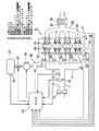
図1は本発明の実施の形態の一実施例にかかる水素エンジン用制御装置が適用された水素エンジン及びその周辺機器を示す概略構成図である。
【0016】
図1において、10は水素を燃料とする4サイクル4気筒からなる水素エンジンであり、水素エンジン10の吸気通路11に導入される空気は、上流側からエアクリーナ12にて清浄され、エアフローメータ13にて計測され、スロットルバルブ14にて調整されたのちインテークマニホルド17を通って、各気筒に対応するインジェクタ18a〜18dから噴射供給される水素燃料と混合され、所定の混合気としてそれぞれの気筒に供給され、所定タイミングにて点火燃焼される。ここで、各気筒の点火系統については省略されている。なお、スロットルバルブ14のスロットル開度はスロットル開度センサ15にて検出され、スロットルバルブ14の下流側の吸気通路11における吸気圧が吸気圧センサ16にて検出される。
【0017】
水素エンジン10の各気筒に配設された吸気バルブ19は、吸気側カムシャフト20により開閉される。この吸気側カムシャフト20には吸気側可変バルブタイミング制御機構21が配設されている。また、水素エンジン10の各気筒に配設された排気バルブ24は、排気側カムシャフト25により開閉される。この排気側カムシャフト25には排気側可変バルブタイミング制御機構26が配設されている。なお、22は吸気側カムポジションセンサ、23はクランクポジションセンサ、27は排気側カムポジションセンサである。そして、水素エンジン10の各気筒からの排気ガスは、エキゾーストマニホルド28から排気通路29を通り、その途中に配設された触媒コンバータ30によりNOx 等が浄化されたのち排出される。
【0018】
高圧燃料タンク31内に貯留された水素燃料は、燃料遮断弁33を介して減圧レギュレータ34にて低圧燃料とされ、燃料調節機構35により調節され、インテークマニホルド17内との差圧により開閉されるインジェクタ18a〜18dによって各気筒に噴射供給される。なお、高圧燃料タンク31内の燃圧は燃圧センサ32にて検出される。
【0019】
ECU(Electronic Control Unit:電子制御ユニット)40は、周知の各種演算処理を実行する中央処理装置としてのCPU、制御プログラムや制御マップ等を格納したROM、各種データ等を格納するRAM、B/U(バックアップ)RAM、入力回路、出力回路及びそれらを接続するバスライン等からなる論理演算回路として構成されている。
【0020】
ここで、各種センサとして、エアフローメータ13からの吸入空気量、スロットル開度センサ15からのスロットル開度、吸気圧センサ16からの吸気圧、吸気側カムポジションセンサ22からの吸気側カムシャフト20のカムポジション、クランクポジションセンサ23からのクランクシャフト(図示略)のクランクポジション、排気側カムポジションセンサ27からの排気側カムシャフト25のカムポジション、燃圧センサ32からの高圧燃料タンク31内の燃圧等の検出信号がECU40の入力回路に入力されている。そして、ECU40の出力回路から各種アクチュエータとして吸気側可変バルブタイミング制御機構21、排気側可変バルブタイミング制御機構26、燃料遮断弁32、減圧レギュレータ33、燃料調節機構34等に制御信号が出力されている。
【0021】
吸気側可変バルブタイミング制御機構21によって、クランクポジションセンサ23に対する吸気側カムポジションセンサ22の偏差が所定クランク角〔°CA(Crank Angle)〕となるよう吸気側カムシャフト20が変位され、吸気バルブ19の開閉タイミングが進角/遅角される。また、排気側可変バルブタイミング制御機構26によって、クランクポジションセンサ23に対する排気側カムポジションセンサ27の偏差が所定クランク角〔°CA〕となるよう排気側カムシャフト25が変位され、排気バルブ24の開閉タイミングが進角/遅角される。そして、吸気側可変バルブタイミング制御機構21による吸気バルブ19の開閉タイミングと排気側可変バルブタイミング制御機構26による排気バルブ24の開閉タイミングとに基づくバルブオーバラップ量によって後述の内部EGR量が設定される。
【0022】
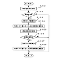
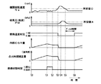
次に、本発明の実施の形態の一実施例にかかる水素エンジン用制御装置で使用されているECU40におけるEGR制御の処理手順を示す図2のフローチャートに基づき、図5を参照して説明する。ここで、図5は図2、後述の図3及び図4の処理に対応する各種センサ信号や各種制御量等の遷移状態を示すタイムチャートである。なお、このEGR制御ルーチンは所定時間毎にECU40にて繰返し実行される。
【0023】
図2において、まず、ステップS101にて、後述の燃焼温度判定処理が実行される。次にステップS102に移行して、燃焼温度が低いかが判定される。ステップS102の判定条件が成立、即ち、水素エンジン10における燃焼温度が低いと判定されたとき(図5に示す時刻t0 〜時刻t3 、時刻t6 以降)にはステップS103に移行し、吸気側可変バルブタイミング制御機構21及び排気側可変バルブタイミング制御機構26による内部EGR量が所定量だけ増加される。次にステップS104に移行して、ステップS103で増加された内部EGR量に応じて点火時期補正量として現在の点火時期から進角側への補正量が設定される。
【0024】
次にステップS105に移行して、後述の燃焼状態判定処理が実行される。次にステップS106に移行して、燃焼状態が悪化しているかが判定される。ステップS106の判定条件が成立、即ち、水素エンジン10における燃焼状態が悪化していると判定されたとき(図5に示す時刻t1 〜時刻t2 )にはステップS107に移行し、吸気側可変バルブタイミング制御機構21及び排気側可変バルブタイミング制御機構26による内部EGR量が所定量だけ減少される。次にステップS108に移行して、ステップS107で減少された内部EGR量に応じて点火時期補正量として現在の点火時期から遅角側への補正量が設定される。
【0025】
一方、ステップS102の判定条件が成立せず、即ち、水素エンジン10における燃焼温度が高いと判定されたとき、またはステップS106の判定条件が成立せず、即ち、水素エンジン10における燃焼状態が良好と判定されたときには、何もすることなく本ルーチンを終了する。
【0026】
次に、図2における燃焼温度判定の処理手順を示す図3のフローチャートに基づき、図5を参照して説明する。
【0027】
図3において、ステップS201で、水素エンジン10の負荷としての吸気圧センサ16にて検出された吸気圧PM〔kPa〕が所定値Aを越えているかが判定される。ステップS201の判定条件が成立、即ち、水素エンジン10の負荷としての吸気圧PMが所定値Aを越え大きいとき(図5に示す時刻t4 〜時刻t5 )にはステップS202に移行し、カウンタTi が「+1」インクリメントされる。次にステップS203に移行して、カウンタTi が所定値Bを越えているかが判定される。ステップS203の判定条件が成立、即ち、カウンタTi が所定値Bを越え大きいときにはステップS204に移行し、水素エンジン10が所定期間、高負荷状態にあり、燃焼温度が高いと判定され、本ルーチンを終了する。
【0028】
一方、ステップS201の判定条件が成立せず、即ち、水素エンジン10の負荷としての吸気圧PMが所定値A以下と小さいとき(図5に示す時刻t4 以前、時刻t5 以降)、またはステップS203の判定条件が成立せず、即ち、カウンタTi が所定値B以下と小さいときにはステップS205に移行する。ステップS205では、クランクポジションセンサ23からのクランクポジション信号に基づく機関回転速度Ne〔rpm〕が所定値Cを越えているかが判定される。ステップS205の判定条件が成立、即ち、水素エンジン10の機関回転速度Neが所定値Cを越え高いとき(図5に示す時刻t3 〜時刻t5 )にはステップS206に移行し、カウンタSi が「+1」インクリメントされる。次にステップS207に移行して、カウンタSi が所定値Dを越え大きいときにはステップS204に移行し、水素エンジン10が所定期間、高回転状態にあり、燃焼温度が高いと判定され、本ルーチンを終了する。
【0029】
一方、ステップS205の判定条件が成立せず、即ち、水素エンジン10の機関回転速度Neが所定値C以下と低いとき(図5に示す時刻t3 以前、時刻t5 以降)、またはステップS207の判定条件が成立せず、即ち、カウンタSi が所定値D以下と小さいときにはステップS208に移行する。ステップS208では、以前の燃焼温度高判定後、所定時間以上経過しているかが判定される。ステップS208の判定条件が成立、即ち、以前に燃焼温度が高いと判定されたのち所定時間以上が経過しているときにはステップS209に移行し、燃焼温度が低いと判定され、本ルーチンを終了する。一方、ステップS208の判定条件が成立せず、即ち、以前に燃焼温度が高いと判定されたのち所定時間以上が経過していないときには、何もすることなく本ルーチンを終了する。
【0030】
このように、機関回転速度Neが一旦所定値Cを越え、または吸気圧PMが一旦所定値Aを越えたのち、両方共に所定値以下となっても、直ちに燃焼温度低判定とされることなく所定時間としてのディレイ時間(図5に示す時刻t5 〜時刻t6 )が経過するまで、即ち、実際の燃焼温度が低くなったと考えられるまでEGRが禁止されるよう、燃焼温度低判定が行われない。
【0031】
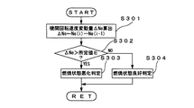
次に、図2における燃焼状態判定の処理手順を示す図4のフローチャートに基づき、図5を参照して説明する。
【0032】
図4において、ステップS301で、クランクポジションセンサ23からのクランクポジション信号に基づく今回の機関回転速度Ne(i)から前回の機関回転速度Ne(i−1)が減算され機関回転速度変動量ΔNe〔rpm〕が算出される。次にステップS302に移行して、ステップS301で算出された機関回転速度変動量ΔNeが所定値Eを越えているかが判定される。ステップS302の判定条件が成立、即ち、機関回転速度変動量ΔNeが所定値Eを越え大きいとき(図5に示す時刻t1 〜時刻t2 )にはステップS303に移行し、燃焼状態が悪化していると判定され、本ルーチンを終了する。一方、ステップS302の判定条件が成立せず、即ち、機関回転速度変動量ΔNeが所定値E以下と小さいときにはステップS304に移行し、燃焼状態が良好と判定され、本ルーチンを終了する。
【0033】
このように、本実施例の水素エンジン用制御装置は、水素を燃料とする水素エンジン10と、水素エンジン10の燃焼温度を判定するECU40にて達成される燃焼温度判定手段と、水素エンジン10の点火時期を制御するECU40にて達成される点火時期制御手段と、前記燃焼温度判定手段により燃焼温度が低いと判定されたときには、水素エンジン10のEGR(排気ガス再循環)させると同時に、前記点火時期制御手段により点火時期も進角させるECU40にて達成される再循環制御手段とを具備するものである。
【0034】
つまり、水素エンジン10の燃焼温度が低いと判定されたときには、EGRが行われると同時に点火時期も進角される。これにより、水素エンジンにおける点火速度の低下と相まってバックファイア等の発生を防止しつつ、NOx の低減と共に、燃費を向上することができる。
【0035】
また、本実施例の水素エンジン用制御装置は、水素エンジン10の負荷として吸気圧PMを検出する負荷検出手段としての吸気圧センサ16と、水素エンジン10の機関回転速度Neを検出する回転速度検出手段としてのクランクポジションセンサ23とを具備し、ECU40にて達成される燃焼温度判定手段は、吸気圧センサ16により低負荷、かつクランクポジションセンサ23により低回転が検出されたときには、燃焼温度が低いと判定するものである。これにより、水素エンジン10における燃焼温度の高/低判定ができ、実際の燃焼温度を検出するセンサ等が省略できるため、構成が簡単で安価なシステムを構築することができる。
【0036】
そして、本実施例の水素エンジン用制御装置のECU40にて達成される再循環制御手段は、吸気圧センサ16による吸気圧PMが所定期間としてカウンタTi が所定値Bを越える高負荷、即ち、高吸気圧またはクランクポジションセンサ23による機関回転速度Neが所定期間としてカウンタSi が所定値Dを越える高回転のうち少なくとも一方の運転条件が検出されたのち、吸気圧センサ16による低吸気圧、かつクランクポジションセンサ23による低回転が検出されても、EGRを所定期間としてディレイ時間、禁止するものである。つまり、水素エンジン10の所定期間以上の高吸気圧、所定期間以上の高回転直後では、燃焼温度が高くなっていると考えられ、この際、ディレイ時間だけEGRが禁止されることで確実に燃焼温度が低くなったときに再度EGRが開始されることとなるため、バックファイア等によるドライバビリティの悪化を未然に防止することができる。
【0037】
更に、本実施例の水素エンジン用制御装置は、水素エンジン10の駆動軸としてのクランクシャフト(図示略)から吸気バルブ19及び排気バルブ24を開閉する従動軸としての吸気側カムシャフト20及び排気側カムシャフト25に駆動力を伝達する駆動力伝達系に設けられ、吸気バルブ19及び排気バルブ24の開閉タイミングを変更自在な吸気側可変バルブタイミング制御機構21及び排気側可変バルブタイミング制御機構26を具備し、ECU40にて達成される再循環制御手段は、吸気側可変バルブタイミング制御機構21及び排気側可変バルブタイミング制御機構26によるバルブオーバラップ量を可変することで内部EGRさせるものである。これにより、水素エンジン10における内部EGR量を必要に応じて簡単に変更することができる。
【0038】
更にまた、本実施例の水素エンジン用制御装置は、水素エンジン10の燃焼状態を判定するECU40にて達成される燃焼状態判定手段を具備し、ECU40にて達成される再循環制御手段が、前記燃焼状態判定手段により燃焼状態の悪化が判定されたときには、EGR量を減少させるものである。これにより、水素エンジン10における過度なEGR量の供給を抑え、バックファイア等によるドライバビリティの悪化を未然に防止することができる。
【0039】
加えて、本実施例の水素エンジン用制御装置は、水素エンジン10の機関回転速度Neを検出する回転速度検出手段としてのクランクポジションセンサ23を具備し、ECU40にて達成される燃焼状態判定手段が、クランクポジションセンサ23による機関回転速度変動量ΔNeに基づき燃焼状態の悪化を判定するものである。これにより、水素エンジン10の燃焼の悪化が簡単に判定でき、安価なシステムを構築することができる。
【0040】
ところで、上記実施例では、EGR制御として吸気側可変バルブタイミング制御機構21及び排気側可変バルブタイミング制御機構26を用いて水素エンジン10に対する内部EGR量を増加/減少させているが、本発明を実施する場合には、これに限定されるものではなく、周知の外部EGR機構を用いて排気通路側から吸気通路側へ外部EGR量を増加/減少させることもでき、上述の実施例と同様の作用・効果が期待できる。
【0041】
また、上記実施例では、EGR制御としてEGR量の増加/減少と同時に、点火時期の進角側/遅角側への補正量も設定されているが、本発明を実施する場合には、これに限定されるものではなく、EGR量の増加/減少のみであってもよい。
【0042】
そして、上記実施例では、水素エンジン10の負荷として吸気圧センサ16により検出される吸気圧PMを用いているが、本発明を実施する場合には、これに限定されるものではなく、エアフローメータ13により検出される吸入空気量等を用いることもできる。
【図面の簡単な説明】
【図1】図1は本発明の実施の形態の一実施例にかかる水素エンジン用制御装置が適用された水素エンジン及びその周辺機器を示す概略構成図である。
【図2】図2は本発明の実施の形態の一実施例にかかる水素エンジン用制御装置で使用されているECUにおけるEGR制御の処理手順を示すフローチャートである。
【図3】図3は図2における燃焼温度判定の処理手順を示すフローチャートである。
【図4】図4は図2における燃焼状態判定の処理手順を示すフローチャートである。
【図5】図5は図2乃至図4の処理に対応する各種センサ信号や各種制御量等の遷移状態を示すタイムチャートである。
【符号の説明】
10 水素エンジン
16 吸気圧センサ
19 吸気バルブ
20 吸気側カムシャフト
21 吸気側可変バルブタイミング制御機構
22 吸気側カムポジションセンサ
23 クランクポジションセンサ
24 排気バルブ
25 排気側カムシャフト
26 排気側可変バルブタイミング制御機構
27 排気側カムポジションセンサ
40 ECU(電子制御ユニット)[0001]
TECHNICAL FIELD OF THE INVENTION
The present invention relates to a hydrogen engine control device for recirculating exhaust gas in a hydrogen engine using hydrogen fuel.
[0002]
[Prior art]
2. Description of the Related Art Conventionally, in a hydrogen engine using hydrogen fuel, the fuel is ignited by touching a wall surface (for example, an intake valve) in a combustion chamber where the temperature of the hydrogen fuel becomes high, or the hydrogen fuel is ignited before ignition. There is a phenomenon that a backfire or the like easily occurs. This is due to the property that hydrogen fuel has a very high lean burn limit and a minimum ignition energy as compared with gasoline fuel. For this reason, exhaust gas recirculation (hereinafter simply referred to as “EGR”), which is well-known in gasoline engines, for the purpose of reducing NOx (nitrogen oxides) is difficult and is not usually performed. Was the current situation.
[0003]
[Problems to be solved by the invention]
By the way, in the EGR of the gasoline engine, the setting is such that the EGR amount is set to be small in a low load / low rotation region and the EGR amount is increased in a high load / high rotation range. This is because, due to the characteristic that gasoline has a low lean burn limit, if the EGR amount is increased at a low load and a low rotation speed, the combustion state is deteriorated, and the drivability is deteriorated.
[0004]
However, as described above, the hydrogen fuel used in the hydrogen engine has a higher lean combustion limit than gasoline fuel, so that a large amount of EGR is possible, and it is desired to implement EGR to reduce NOx and improve fuel efficiency. The request was strong.
[0005]
In order to satisfy such a demand, there is a problem that backfire or the like due to the above-mentioned early ignition must not be caused.
[0006]
Accordingly, the present invention has been made to solve such a problem, and is intended for a hydrogen engine capable of reducing NOx and improving fuel efficiency while preventing the occurrence of backfire or the like due to EGR (exhaust gas recirculation) in the hydrogen engine. The task is to provide a control device.
[0007]
[Means for Solving the Problems]
According to the hydrogen engine control device of the first aspect, when the combustion temperature determination means determines that the combustion temperature of the hydrogen engine is low, EGR (exhaust gas recirculation) is performed by the recirculation control means. And the like, while reducing NOx and improving fuel economy.
[0008]
According to the second aspect of the present invention, when the combustion temperature of the hydrogen engine is determined to be low by the combustion temperature determining means, the ignition timing is advanced by the ignition timing control means simultaneously with the EGR by the recirculation control means. This prevents the occurrence of backfire or the like in conjunction with the decrease in the ignition speed, thereby reducing NOx and improving fuel efficiency.
[0009]
The combustion temperature determining means in the hydrogen engine control device determines that the combustion temperature in the hydrogen engine is low when the load detecting means detects a low load and the rotation speed detecting means detects a low rotation. As a result, the combustion temperature of the hydrogen engine can be determined to be high or low, so that a sensor or the like for detecting the actual combustion temperature can be omitted, and a simple and inexpensive system can be constructed.
[0010]
In the recirculation control means in the hydrogen engine control device according to claim 4, after the load detecting means detects at least one of the high load for a predetermined period or more and the high speed for a predetermined period or more by the rotation speed detecting means, the operating condition is detected. Even if a low load is detected by the load detecting means and a low rotation is detected by the rotational speed detecting means, the EGR in the hydrogen engine is prohibited for a predetermined period. That is, it is considered that the combustion temperature is high immediately after the high load of the hydrogen engine for a predetermined period or more and the high speed rotation for a predetermined period or more, and the combustion temperature is surely lowered by prohibiting the EGR for a predetermined period. When this happens, the EGR is started again, so that drivability is prevented from deteriorating due to backfire or the like.
[0011]
In the recirculation control means in the hydrogen engine control device according to the fifth aspect, the internal EGR amount in the hydrogen engine can be simplified as necessary by varying the valve overlap amount of the intake valve and the exhaust valve by the variable valve timing control mechanism. Can be changed to
[0012]
In the recirculation control means of the control apparatus for a hydrogen engine according to the sixth aspect, when the combustion state determination means determines that the combustion state of the hydrogen engine has deteriorated, the EGR amount in the hydrogen engine is reduced. As a result, excessive supply of the EGR amount is suppressed, and deterioration of drivability due to backfire or the like is prevented.
[0013]
In the combustion state determination means in the hydrogen engine control device of the seventh aspect, the deterioration of the combustion state is determined based on the fluctuation amount of the engine speed of the hydrogen engine by the rotation speed / speed detection means. As described above, since the deterioration of the combustion state of the hydrogen engine can be easily determined, an inexpensive system can be constructed.
[0014]
BEST MODE FOR CARRYING OUT THE INVENTION
Hereinafter, embodiments of the present invention will be described based on examples.
[0015]
FIG. 1 is a schematic configuration diagram showing a hydrogen engine to which a hydrogen engine control device according to one example of an embodiment of the present invention is applied and peripheral devices thereof.
[0016]
In FIG. 1,
[0017]
An
[0018]
The hydrogen fuel stored in the high-
[0019]
An ECU (Electronic Control Unit) 40 includes a CPU as a central processing unit for executing various known arithmetic processing, a ROM for storing a control program and a control map, a RAM for storing various data, and a B / U. (Backup) It is configured as a logic operation circuit including a RAM, an input circuit, an output circuit, and a bus line connecting them.
[0020]
Here, as various sensors, the intake air amount from the
[0021]
The intake-
[0022]
Next, a description will be given with reference to FIG. 5 based on a flowchart of FIG. 2 showing a processing procedure of the EGR control in the
[0023]
In FIG. 2, first, in step S101, a combustion temperature determination process described later is executed. Next, the process proceeds to step S102, where it is determined whether the combustion temperature is low. When the determination condition of step S102 is satisfied, that is, when it is determined that the combustion temperature in the
[0024]
Next, the process proceeds to step S105, and a combustion state determination process described later is executed. Next, the process proceeds to step S106, and it is determined whether the combustion state has deteriorated. When the determination condition in step S106 is satisfied, that is, when it is determined that the combustion state in the
[0025]
On the other hand, when the determination condition in step S102 is not satisfied, that is, when it is determined that the combustion temperature in the
[0026]
Next, a description will be given with reference to FIG. 5 based on a flowchart of FIG. 3 showing a processing procedure of the combustion temperature determination in FIG.
[0027]
In FIG. 3, in step S201, it is determined whether the intake pressure PM [kPa] detected by the
[0028]
On the other hand, when the determination condition of step S201 is not satisfied, that is, when the intake pressure PM as the load of the
[0029]
On the other hand, when the determination condition of step S205 is not satisfied, that is, when the engine rotation speed Ne of the
[0030]
As described above, even if the engine rotational speed Ne once exceeds the predetermined value C or the intake pressure PM once exceeds the predetermined value A, and if both become lower than the predetermined value, the combustion temperature is not immediately determined to be low. The combustion temperature low determination is not performed until the delay time (time t5 to time t6 shown in FIG. 5) as a predetermined time elapses, that is, until the actual combustion temperature is considered to be low, so that the EGR is prohibited. .
[0031]
Next, a description will be given with reference to FIG. 5 based on the flowchart of FIG. 4 showing the processing procedure of the combustion state determination in FIG.
[0032]
In FIG. 4, in step S301, the previous engine speed Ne (i-1) is subtracted from the current engine speed Ne (i) based on the crank position signal from the crank position sensor 23, and the engine speed fluctuation amount ΔNe [ rpm] is calculated. Next, the process proceeds to step S302, and it is determined whether the engine speed fluctuation amount ΔNe calculated in step S301 exceeds a predetermined value E. When the determination condition of step S302 is satisfied, that is, when the engine speed fluctuation amount ΔNe exceeds the predetermined value E and is large (time t1 to time t2 shown in FIG. 5), the process proceeds to step S303, and the combustion state is deteriorated. Is determined, and this routine ends. On the other hand, when the determination condition of step S302 is not satisfied, that is, when the engine speed fluctuation amount ΔNe is smaller than the predetermined value E, the process proceeds to step S304, the combustion state is determined to be good, and this routine ends.
[0033]
As described above, the control apparatus for a hydrogen engine according to the present embodiment includes the
[0034]
That is, when it is determined that the combustion temperature of the
[0035]
Further, the control device for a hydrogen engine of the present embodiment includes an
[0036]
The recirculation control means achieved by the
[0037]
Further, the control apparatus for a hydrogen engine according to the present embodiment includes an
[0038]
Furthermore, the control apparatus for a hydrogen engine according to the present embodiment includes a combustion state determination unit that is achieved by the
[0039]
In addition, the control device for a hydrogen engine according to the present embodiment includes a crank position sensor 23 as a rotation speed detection unit that detects the engine rotation speed Ne of the
[0040]
In the above embodiment, the internal EGR amount with respect to the
[0041]
Further, in the above embodiment, the correction amount of the ignition timing to the advance side / retard side is set at the same time as the increase / decrease of the EGR amount as the EGR control. However, the present invention is not limited to this, and may be only the increase / decrease of the EGR amount.
[0042]
In the above embodiment, the intake pressure PM detected by the
[Brief description of the drawings]
FIG. 1 is a schematic configuration diagram showing a hydrogen engine to which a control device for a hydrogen engine according to an embodiment of the present invention is applied and peripheral devices thereof.
FIG. 2 is a flowchart illustrating a processing procedure of EGR control in an ECU used in the hydrogen engine control device according to one example of the embodiment of the present invention.
FIG. 3 is a flowchart illustrating a processing procedure for determining a combustion temperature in FIG. 2;
FIG. 4 is a flowchart showing a processing procedure for determining a combustion state in FIG. 2;
FIG. 5 is a time chart showing transition states of various sensor signals, various control amounts, and the like corresponding to the processes of FIGS. 2 to 4;
[Explanation of symbols]
Claims (7)
前記水素エンジンの燃焼温度を判定する燃焼温度判定手段と、
前記燃焼温度判定手段により燃焼温度が低いと判定されたときには、前記水素エンジンの排気ガスを再循環させる再循環制御手段と
を具備することを特徴とする水素エンジン用制御装置。A hydrogen engine powered by hydrogen,
Combustion temperature determination means for determining a combustion temperature of the hydrogen engine;
A recirculation control unit for recirculating exhaust gas of the hydrogen engine when the combustion temperature determination unit determines that the combustion temperature is low.
前記水素エンジンの燃焼温度を判定する燃焼温度判定手段と、
前記水素エンジンの点火時期を制御する点火時期制御手段と、
前記燃焼温度判定手段により燃焼温度が低いと判定されたときには、前記水素エンジンの排気ガスを再循環させると同時に、前記点火時期制御手段により点火時期も進角させる再循環制御手段と
を具備することを特徴とする水素エンジン用制御装置。A hydrogen engine powered by hydrogen,
Combustion temperature determination means for determining a combustion temperature of the hydrogen engine;
Ignition timing control means for controlling the ignition timing of the hydrogen engine,
Recirculation control means for recirculating the exhaust gas of the hydrogen engine when the combustion temperature determination means determines that the combustion temperature is low, and at the same time advancing the ignition timing by the ignition timing control means. A control device for a hydrogen engine.
前記水素エンジンの機関回転速度を検出する回転速度検出手段とを具備し、
前記燃焼温度判定手段は、前記負荷検出手段により低負荷、かつ前記回転速度検出手段により低回転が検出されたときには、前記燃焼温度が低いと判定することを特徴とする請求項1または請求項2に記載の水素エンジン用制御装置。Load detection means for detecting a load on the hydrogen engine,
Rotation speed detection means for detecting the engine rotation speed of the hydrogen engine,
3. The combustion temperature judging means judges that the combustion temperature is low when a low load is detected by the load detecting means and a low rotation is detected by the rotational speed detecting means. 3. The control device for a hydrogen engine according to 1.
前記再循環制御手段は、前記可変バルブタイミング制御機構によるバルブオーバラップ量を可変することで前記排気ガスを再循環させることを特徴とする請求項1または請求項2に記載の水素エンジン用制御装置。A driving force transmission system that transmits driving force from a driving shaft of the hydrogen engine to a driven shaft that opens and closes at least one of an intake valve and an exhaust valve, and controls an opening / closing timing or a lift amount of the intake valve or the exhaust valve. Equipped with a variable valve timing control mechanism that can be changed,
3. The hydrogen engine control device according to claim 1, wherein the recirculation control unit recirculates the exhaust gas by changing a valve overlap amount by the variable valve timing control mechanism. .
前記再循環制御手段は、前記燃焼状態判定手段により燃焼状態の悪化が判定されたときには、前記排気ガスの再循環量を減少させることを特徴とする請求項1または請求項2に記載の水素エンジン用制御装置。A combustion state determination unit that determines a combustion state of the hydrogen engine;
3. The hydrogen engine according to claim 1, wherein the recirculation control unit reduces the recirculation amount of the exhaust gas when the combustion state determination unit determines that the combustion state has deteriorated. 4. Control device.
前記燃焼状態判定手段は、前記回転速度検出手段による機関回転速度の変動量に基づき燃焼状態の悪化を判定することを特徴とする請求項6に記載の水素エンジン用制御装置。A rotation speed detection unit that detects an engine rotation speed of the hydrogen engine,
The control apparatus for a hydrogen engine according to claim 6, wherein the combustion state determination unit determines the deterioration of the combustion state based on a variation amount of the engine rotation speed by the rotation speed detection unit.
Priority Applications (1)
| Application Number | Priority Date | Filing Date | Title |
|---|---|---|---|
| JP2003138931A JP2004340065A (en) | 2003-05-16 | 2003-05-16 | Control device for hydrogen engine |
Applications Claiming Priority (1)
| Application Number | Priority Date | Filing Date | Title |
|---|---|---|---|
| JP2003138931A JP2004340065A (en) | 2003-05-16 | 2003-05-16 | Control device for hydrogen engine |
Publications (1)
| Publication Number | Publication Date |
|---|---|
| JP2004340065A true JP2004340065A (en) | 2004-12-02 |
Family
ID=33528162
Family Applications (1)
| Application Number | Title | Priority Date | Filing Date |
|---|---|---|---|
| JP2003138931A Pending JP2004340065A (en) | 2003-05-16 | 2003-05-16 | Control device for hydrogen engine |
Country Status (1)
| Country | Link |
|---|---|
| JP (1) | JP2004340065A (en) |
Cited By (8)
| Publication number | Priority date | Publication date | Assignee | Title |
|---|---|---|---|---|
| EP1754874A1 (en) | 2005-08-18 | 2007-02-21 | Mazda Motor Corporation | Method and apparatus for controlling an internal combustion engine |
| JP2007077891A (en) * | 2005-09-14 | 2007-03-29 | Mazda Motor Corp | Fuel changeover control device of dual fuel engine |
| JP2007085295A (en) * | 2005-09-26 | 2007-04-05 | Mazda Motor Corp | Fuel switching control device of dual-fuel engine |
| JP2007211608A (en) * | 2006-02-07 | 2007-08-23 | Mazda Motor Corp | Control device for hydrogen engine |
| JP2008240704A (en) * | 2007-03-28 | 2008-10-09 | Denso Corp | Control device for internal combustion engine |
| JP2016130506A (en) * | 2015-01-15 | 2016-07-21 | マツダ株式会社 | Fuel control device of multi-fuel engine |
| JP2017194052A (en) * | 2016-04-19 | 2017-10-26 | ヤマハ発動機株式会社 | Engine unit and saddle-riding type vehicle |
| CN107687388A (en) * | 2016-08-05 | 2018-02-13 | 现代自动车株式会社 | Equipment for the tempering that prevents engine and the method using the equipment |
-
2003
- 2003-05-16 JP JP2003138931A patent/JP2004340065A/en active Pending
Cited By (12)
| Publication number | Priority date | Publication date | Assignee | Title |
|---|---|---|---|---|
| EP1754874A1 (en) | 2005-08-18 | 2007-02-21 | Mazda Motor Corporation | Method and apparatus for controlling an internal combustion engine |
| JP2007077891A (en) * | 2005-09-14 | 2007-03-29 | Mazda Motor Corp | Fuel changeover control device of dual fuel engine |
| JP2007085295A (en) * | 2005-09-26 | 2007-04-05 | Mazda Motor Corp | Fuel switching control device of dual-fuel engine |
| JP4600231B2 (en) * | 2005-09-26 | 2010-12-15 | マツダ株式会社 | Dual fuel engine fuel switching control device |
| JP2007211608A (en) * | 2006-02-07 | 2007-08-23 | Mazda Motor Corp | Control device for hydrogen engine |
| JP4618150B2 (en) * | 2006-02-07 | 2011-01-26 | マツダ株式会社 | Control device for hydrogen engine |
| JP2008240704A (en) * | 2007-03-28 | 2008-10-09 | Denso Corp | Control device for internal combustion engine |
| JP2016130506A (en) * | 2015-01-15 | 2016-07-21 | マツダ株式会社 | Fuel control device of multi-fuel engine |
| JP2017194052A (en) * | 2016-04-19 | 2017-10-26 | ヤマハ発動機株式会社 | Engine unit and saddle-riding type vehicle |
| CN107687388A (en) * | 2016-08-05 | 2018-02-13 | 现代自动车株式会社 | Equipment for the tempering that prevents engine and the method using the equipment |
| US10260476B2 (en) | 2016-08-05 | 2019-04-16 | Hyundai Motor Company | Device for preventing back fire of engine and method using the same |
| CN107687388B (en) * | 2016-08-05 | 2020-08-28 | 现代自动车株式会社 | Apparatus for preventing backfire of engine and method of using the same |
Similar Documents
| Publication | Publication Date | Title |
|---|---|---|
| US7287500B2 (en) | Start controller for internal combustion engine | |
| JP5779331B2 (en) | In-cylinder injection gasoline engine controller | |
| JP2005351215A (en) | Control system of internal combustion engine | |
| JP2010059921A (en) | Egr control device of internal combustion engine | |
| JP3680259B2 (en) | Fuel injection device for diesel engine | |
| JPWO2004018869A1 (en) | Start control device and start control method for internal combustion engine | |
| JP2008208741A (en) | Control device for internal combustion engine | |
| JP2006291939A (en) | Controller of engine | |
| US7063056B2 (en) | Valve timing control apparatus for engine | |
| JP2004340065A (en) | Control device for hydrogen engine | |
| JP2004027971A (en) | Controller for internal combustion engine | |
| JP2006291940A (en) | Controller of engine | |
| JP2010236398A (en) | Internal combustion engine with catalyst warming-up control | |
| JP4415864B2 (en) | Control device for internal combustion engine | |
| US20160369729A1 (en) | Control apparatus and control method for internal combustion engine | |
| JP2010168931A (en) | Ignition timing control device for spark ignition type internal combustion engine | |
| JP2007077842A (en) | Control device for internal combustion engine | |
| JP2006132399A (en) | Control device and control method for an engine with supercharger | |
| JP2004183581A (en) | Exhaust emission control device for internal combustion engine | |
| JP2005016396A (en) | Catalyst warming-up system of internal combustion engine | |
| JP2008232095A (en) | Control device for internal combustion engine | |
| JP4415803B2 (en) | Control device for internal combustion engine | |
| JP2006132400A (en) | Fuel injection control method of internal combustion engine | |
| JP2011099399A (en) | Control method and control device of internal combustion engine | |
| JP2001098964A (en) | Controller for spark ignition type direct injection engine |