JP2004334531A - Control system, control method, print system, image data controller, and program - Google Patents
Control system, control method, print system, image data controller, and program Download PDFInfo
- Publication number
- JP2004334531A JP2004334531A JP2003129476A JP2003129476A JP2004334531A JP 2004334531 A JP2004334531 A JP 2004334531A JP 2003129476 A JP2003129476 A JP 2003129476A JP 2003129476 A JP2003129476 A JP 2003129476A JP 2004334531 A JP2004334531 A JP 2004334531A
- Authority
- JP
- Japan
- Prior art keywords
- external device
- program
- printer
- control
- dsc
- Prior art date
- Legal status (The legal status is an assumption and is not a legal conclusion. Google has not performed a legal analysis and makes no representation as to the accuracy of the status listed.)
- Withdrawn
Links
Images


Classifications
-
- H—ELECTRICITY
- H04—ELECTRIC COMMUNICATION TECHNIQUE
- H04N—PICTORIAL COMMUNICATION, e.g. TELEVISION
- H04N1/00—Scanning, transmission or reproduction of documents or the like, e.g. facsimile transmission; Details thereof
- H04N1/00127—Connection or combination of a still picture apparatus with another apparatus, e.g. for storage, processing or transmission of still picture signals or of information associated with a still picture
- H04N1/00278—Connection or combination of a still picture apparatus with another apparatus, e.g. for storage, processing or transmission of still picture signals or of information associated with a still picture with a printing apparatus, e.g. a laser beam printer
-
- H—ELECTRICITY
- H04—ELECTRIC COMMUNICATION TECHNIQUE
- H04N—PICTORIAL COMMUNICATION, e.g. TELEVISION
- H04N1/00—Scanning, transmission or reproduction of documents or the like, e.g. facsimile transmission; Details thereof
- H04N1/00127—Connection or combination of a still picture apparatus with another apparatus, e.g. for storage, processing or transmission of still picture signals or of information associated with a still picture
- H04N1/00132—Connection or combination of a still picture apparatus with another apparatus, e.g. for storage, processing or transmission of still picture signals or of information associated with a still picture in a digital photofinishing system, i.e. a system where digital photographic images undergo typical photofinishing processing, e.g. printing ordering
- H04N1/00143—Ordering
- H04N1/00145—Ordering from a remote location
-
- H—ELECTRICITY
- H04—ELECTRIC COMMUNICATION TECHNIQUE
- H04N—PICTORIAL COMMUNICATION, e.g. TELEVISION
- H04N1/00—Scanning, transmission or reproduction of documents or the like, e.g. facsimile transmission; Details thereof
- H04N1/00127—Connection or combination of a still picture apparatus with another apparatus, e.g. for storage, processing or transmission of still picture signals or of information associated with a still picture
- H04N1/00132—Connection or combination of a still picture apparatus with another apparatus, e.g. for storage, processing or transmission of still picture signals or of information associated with a still picture in a digital photofinishing system, i.e. a system where digital photographic images undergo typical photofinishing processing, e.g. printing ordering
- H04N1/00167—Processing or editing
-
- H—ELECTRICITY
- H04—ELECTRIC COMMUNICATION TECHNIQUE
- H04N—PICTORIAL COMMUNICATION, e.g. TELEVISION
- H04N1/00—Scanning, transmission or reproduction of documents or the like, e.g. facsimile transmission; Details thereof
- H04N1/0035—User-machine interface; Control console
- H04N1/00352—Input means
- H04N1/00395—Arrangements for reducing operator input
-
- H—ELECTRICITY
- H04—ELECTRIC COMMUNICATION TECHNIQUE
- H04N—PICTORIAL COMMUNICATION, e.g. TELEVISION
- H04N1/00—Scanning, transmission or reproduction of documents or the like, e.g. facsimile transmission; Details thereof
- H04N1/0035—User-machine interface; Control console
- H04N1/00405—Output means
- H04N1/00408—Display of information to the user, e.g. menus
- H04N1/0044—Display of information to the user, e.g. menus for image preview or review, e.g. to help the user position a sheet
- H04N1/00458—Sequential viewing of a plurality of images, e.g. browsing or scrolling
-
- H—ELECTRICITY
- H04—ELECTRIC COMMUNICATION TECHNIQUE
- H04N—PICTORIAL COMMUNICATION, e.g. TELEVISION
- H04N1/00—Scanning, transmission or reproduction of documents or the like, e.g. facsimile transmission; Details thereof
- H04N1/32—Circuits or arrangements for control or supervision between transmitter and receiver or between image input and image output device, e.g. between a still-image camera and its memory or between a still-image camera and a printer device
- H04N1/32561—Circuits or arrangements for control or supervision between transmitter and receiver or between image input and image output device, e.g. between a still-image camera and its memory or between a still-image camera and a printer device using a programmed control device, e.g. a microprocessor
- H04N1/32571—Details of system components
- H04N1/32577—Input interface
-
- H—ELECTRICITY
- H04—ELECTRIC COMMUNICATION TECHNIQUE
- H04N—PICTORIAL COMMUNICATION, e.g. TELEVISION
- H04N1/00—Scanning, transmission or reproduction of documents or the like, e.g. facsimile transmission; Details thereof
- H04N1/32—Circuits or arrangements for control or supervision between transmitter and receiver or between image input and image output device, e.g. between a still-image camera and its memory or between a still-image camera and a printer device
- H04N1/32561—Circuits or arrangements for control or supervision between transmitter and receiver or between image input and image output device, e.g. between a still-image camera and its memory or between a still-image camera and a printer device using a programmed control device, e.g. a microprocessor
- H04N1/32571—Details of system components
- H04N1/32587—Controller
Abstract
Description
【0001】
【発明の属する技術分野】
本発明は、制御システム、制御方法、印刷システム、画像データ制御装置及びプログラムに関する。
【0002】
【従来の技術】
近年、デジタルカメラが広く利用されている。デジタルカメラは、被写体の像をデジタルの画像データとして記録する記憶手段を有している。デジタルカメラに記録された画像データは、パーソナルコンピュータ(以下、PCと略す)に接続されたプリンタで印刷するのが一般的である。その場合、ユーザは、デジタルカメラとPCを接続し、デジタルカメラ内の記憶手段に記憶されている画像データを読み出し、その読み出した画像データをプリンタに出力するように、PCを操作してプリンタへ印刷指示を出す。
【0003】
しかし、PCからプリンタへ印刷指示することによって、デジタルカメラの画像データを印刷する方法の場合、ユーザがPCの操作に不慣れであると、容易にデジタルカメラに記憶された画像データの印刷をすることができない。そこで、PCにデジタルカメラを接続すると、自動的に、デジタルカメラからの画像データの取得、印刷データの作成、印刷の実行を行う画像印刷システムが提案されている(例えば、特許文献1参照)。そのシステムによれば、ユーザは、PC等の操作に不慣れであっても、容易に画像データの印刷をすることができる。
【0004】
また、PCを利用してカメラの各種設定をできる装置も提案されている(例えば、特許文献2参照)。PCから撮影モード等の変更を行うことによって、カメラを遠隔で制御することができる。そして、PCに接続されたプリンタの印刷性能を検出し、その性能に合った撮影画像をPCからプリンタへ送信したり、カメラが印刷性能の情報をプリンタに問い合わせて送信依頼をするようにする技術が提案されている。
【0005】
【特許文献1】
特開2001−238156号公報(第2頁から第3頁、第1図)
【0006】
【特許文献2】
特開2000−32321号公報(第18頁から第22頁、図20、図24)
【0007】
【発明が解決しようとする課題】
しかし、デジタルカメラからの画像データの取得、印刷データの作成、及び印刷の実行を自動的に行う画像印刷システムの場合、PC、デジタルカメラ、プリンタは予め決められたものでなければならない。すなわち、PCが画像データを取得するときに、デジタルカメラに記憶されている画像データのフォーマットが予め決められたフォーマットでなければならず、さらに、PCが印刷データの作成及び印刷実行を行うとき、PCに接続されたプリンタに対応した予め決められたフォーマットでなければ処理を実行できない。
【0008】
また、PCがカメラを遠隔制御する技術を利用してカメラを場合であっても、ユーザがPC、プリンタ等の操作に不慣れであると、ユーザはプリンタ等の外部機器への対応をすることは容易ではなかった。
【0009】
そこで、本発明は、PC等の制御機器やプリンタ等の外部機器に不慣れなユーザであっても、これらの機器の整合性を容易に取れ、容易に操作できる制御システムを提供することを目的とする。
【0010】
【課題を解決するための手段】
本発明の制御システムは、プログラムを受信する受信手段を有し、受信手段で受信したプログラムに基づいて動作可能な第1の外部機器と、上記第1の外部機器が受信したプログラムに基づいて上記第1の外部機器から出力されたコマンドに関連して動作可能な第2の外部機器と、上記第1及び第2の外部機器が制御可能に接続されていると判定された際に、上記第1の機器と上記第2の外部機器とが互いに関連して動作するための特定プログラムを選択するとともに、選択された特定プログラムを上記第1の外部機器へ送信する制御機器とからなる制御システムであって、上記第1の外部機器から出力されたコマンドによって、上記第2の外部機器を制御する。
【0011】
【発明の実施の形態】
以下、図面を参照して本発明の実施の形態を説明する。
【0012】
まず図1に基づき、本実施の形態に係わるシステムの構成を説明する。図1は、本実施の形態に係わる画像データ制御システムの構成を示す構成図である。
【0013】
図1において、1はデジタルカメラ(以下、DSCと略す)であり、内蔵されている撮像装置によって撮像された被写体の画像データを、内蔵あるいは接続された記憶媒体に記憶することができる。2は制御装置としてのPCであり、後述するプログラムを記憶する記憶装置、例えばハードディスクドライブ(以下、HDDと略す)を有する。記憶装置には、後述する各種処理、例えば、判定処理、プログラム生成処理、プリンタへの制御コマンド送信処理を行うプログラムが記憶されている。3は、プリンタ装置(以下、プリンタという)であり、受信した画像データに基いて紙等に画像を印刷する。4は光磁気ディスク装置(以下、MOと略す)であり、画像データを記憶することができる。プリンタ3とMO4は、DSC1の画像データの処理、例えば、印刷処理、蓄積処理を行う。
【0014】
PC2とDSC1とはUSB(Universal Serial Bus)等の接続ケーブル5によって接続され、PC2とプリンタ3とはUSB等の接続ケーブル6によって接続され、PC2とMO4とはUSB等の接続ケーブル7によって接続されている。従って、PC2は、接続ケーブル5、6及び7を介して、DSC1、プリンタ3及びMO4とデータ通信をすることができる。PC2は、これらの接続ケーブルを介して、後述するように、生成あるいは選択したプログラムをDSC1へ送信したり、DSC1から受信したデータを、プリンタ制御コマンドに変換してプリンタ3及びMO4へ送信したりすることができる。
【0015】
図2は、DSC1、PC2及びプリンタ3の構造を示すブロック構成図である。DSC1は、CCD(Charge Coupled Device)等の固体撮像素子等を有する撮像部11、DSC1の外装表面に設けられた液晶表示装置(以下、LCDという)を有する表示部12、DSC1の外装表面に設けられ、ユーザによって各種操作をするために設けられたシャッターボタン、セルフタイマーボタン等の操作部13、撮像部11によって取得された被写体像の画像データを記憶する記憶部14、PC2とデータ通信をするための通信インターフェース部(以下、I/F部と略す)15、及び、制御部である中央処理装置(以下、CPUと略す)16を含む。
【0016】
DSC1は、通常のデジタルカメラの機能を有しており、被写体を撮像し、画像データを記憶部14に記憶し、かつ接続ケーブル5を用いてPC2へ接続し、画像データをPC2へ送信することができる。さらに、DFC1は、予め決められたモードにおいて、CPU16とRAM(図示せず)によって、PC2において選択あるいは生成された予め決められた形式のプログラムを受信して実行することができる。予め決められた形式のプログラムを実行することについては後述する。
【0017】
PC2は、LCD等の表示部21、キーボード等の操作部22、各種処理を行う各種プログラム、後述するテーブルデータ等の各種データを記憶するHDD等の記憶部23、DSC1とデータ通信をするためのI/F部24、プリンタ3とデータ通信をするためのI/F部25、及び制御部としてのCPU26を含む。
【0018】
PC2は、通常のコンピュータの機能を有し、さらに、PC2は、記憶部23に記憶された後述する各種処理を実行する機能を有している。
【0019】
プリンタ3は、画像データに対して印刷のための各種画像処理を行う画像処理部31、紙等の媒体に画像を印刷するためのプリンタヘッド32、画像を媒体に印刷するためのデータを記憶する記憶部33、及びPC2とデータ通信をするためのI/F部34、及び制御部としてのCPU35を含む。
【0020】
プリンタ3は、PC2から制御コマンドを受信すると、その制御コマンドに基づいて各種処理を実行する機能を有する。
【0021】
なお、MO4の構成はここでは省略するが、構成は通常の光磁気ディスク装置の構成と同様である。
【0022】
以下、DSC1、PC2及びプリンタ3との間でのデータ通信と、DSC1、PC2及びプリンタ3における処理の例を説明する。
【0023】
PC2は、後述する生成又は選択したプログラムの送信、DSC1からのデータの受信を、I/F24と、接続ケーブル5と、I/F15とを介して行う。同様に、PC2は、後述するプリント制御コマンドの送信、プリンタからの状態情報のデータの受信を、I/F25と、接続ケーブル6と、I/F34とを介して行う。
【0024】
後述するように、本実施の形態によれば、PC2から送信されてDSC1において実行されたプログラムによってDSC1に表示された内容に従って、ユーザがDSC1を操作することによって、プリンタ3等への操作指示を行うことができる。その結果、図1の点線8の矢印で示すように、DSC1のユーザは、DSC1によって、プリンタ3等の操作を行うことができる。
【0025】
図3は、PC2とプリンタ3、そして、PC2とMO4とが接続されている状態で、さらにDSC1をPC2に接続したときに、PC2で実行される処理の流れの例を示すフローチャートである。PC2とプリンタ3とは既に接続されているので、PC2とプリンタ3の間、及びPC2とMO4の間では、PC2からの各種制御コマンドの送信、プリンタ3及びMO4からの状態情報、例えば動作状態等の情報のやり取りが行い得る状態である。
【0026】
まず、PC2は、DSC1とのUSB接続を確認する(ステップ(以下、Sと略す)1)。そして、USB接続が確認されなければ、図3のS1以降の処理は行われない。USB接続が確認されると、S1でYESとなって、次に、DSC1の記憶する画像データをプリンタ3及びMO4が処理可能に、DSC1とプリンタ3等とが接続されているか否かの判定が行われる。
【0027】
まず、S2において、DSCの確認を行う。DSCの確認では、USBを介して接続されているDSCの種類、すなわちメーカ名、型番、ファームウエアのバージョン等の確認を行う。なお、DSCの確認は、通信インターフェースの物理層であるUSBインターフェースの機能を用いて行ってもよいが、DSC1とPC2がPTP(Picture Transfer Protocol)等の画像転送プロトコルをサポートしているときは、その画像転送プロトコルの機能を用いて行ってもよい。
【0028】
次に、PC2は、外部機器であるプリンタ3の確認を行う(S3)。すなわち、プリンタ3の種類、すなわちメーカ名、型番等の確認が行われる。
【0029】
そして、S2とS3の処理の結果、DSC1の記憶する画像データをプリンタ3及びMO4が処理可能に、DSC1とプリンタ3等とが接続されているか否かの判定が行われる(S4)。判定の結果、OKであれば、処理はS5に進む。判定の結果、NGであれば、処理は何もしないで終了する。
【0030】
S4の判定は、例えば、S2とS3において確認されたDSCの種類とプリンタの種類とに対応するプログラムが予め用意されているか否かによって行われる。DSCの種類とプリンタの種類とに対応するプログラムについては後述する。
【0031】
次に、PC2は、DSC1とプリンタ3の組み合せに基いて、PC2の記憶部23に予め記憶された複数のプログラムの中から、DSC1に送信するためのDSC1に適合するプログラムを選択する。PC2の記憶部23には、ユーザがプリンタ3に対する制御コマンドをDSC1において指示できるように、あるいはプリンタ3の状態をDSC1において表示出力できるように、DSCの種類とプリンタの種類とに応じて、複数のプログラムが予め用意されて記憶されている。その予め用意されたプログラム群の中から、S2とS3とにおいて確認された種類に基いて、DSC1に適合する予め決められた形式のプログラムが選択される(S5)。
【0032】
選択されたプログラムは、DSC1へ送信されてDSC1の制御部16において実行され、その結果、ユーザがDSC1からプリンタ3への制御コマンドを指定できるようになる。具体的には、選択されたプログラムがDSC1において実行された結果、後述するように、予め決められたモードにDSC1がセットされ、DSC1の表示部12に所定の表示がされ、ユーザがDSC1の操作部13を用いてプリンタ3への制御コマンドを指定するための入力機能等が実現できるようになる。よって、S5では、DSC1が有している表示部12の画面の大きさ、操作部13のボタンの数、種類等、DSC1の性能、機能、構成等に応じた画面のプログラムが選択される。
【0033】
さらに、プログラムは、プリンタ3の性能、機能、構成等にも応じたものでなければならない。よって、DSC1のメーカ、型番等とプリンタ3のメーカ、型番等に対応して、選択されるプログラムを決定するためのテーブル形式のデータが、PC2の記憶部23に予め記憶されており、プログラムの選択は、PC2の記憶部23に予め記憶されているテーブルデータに基いて行われる。さらに、DSCとプリンタに対応して予め用意されたプログラムが複数、PC2の記憶部23に記憶されている。よって、具体的には、PC2は、S2とS3において確認された、DSC1の型番等とプリンタ3の型番等に基いて、複数のプログラムの中から、DSC1において実行される予め決められた形式のプログラムを選択する。
【0034】
なお、適合するプログラムの選択は、DSC1の種類とプリンタ3の種類ではなく、DSC1の機能とプリンタ3の機能とに対応したテーブルデータに基いて行ってもよい。すなわち、DSCの表示機能、操作機能等を確認し、その確認された機能とプリンタ3の機能とに対応したプログラムを選択するようにしてもよい。例えば、PC2に、ピクトブリッジ(PictBridge)等のダイレクトプリント用のプロトコルも認識可能となっていれば、そのピクトブリッジ等のプロトコルの機能を用いてDSCの機能の確認を行う。
【0035】
具体的には、ピクトブリッジの機能の一つであるディスカバリー機能を用いて、PC2が、DSC1の機能を確認する。例えば、PC2は、PC2からDSC1へ、DSC1がどのような形式のファイルを有しているのかを確認するために仮想ファイルを送信したり、あるいはDSC1へどのようなファイルを有しているのかを示すファイルリストを要求することによって、DSC1の機能を確認し、予め用意されたプログラム群の中から、そのDSCの機能に対応したプログラムを選択する。
【0036】
さらになお、PC2はDSC1へ送信するプログラムを、予め用意された複数のプログラムの中から選択して送信するのではなく、PC2は、DSC1とプリンタ3の種類あるいは機能に適合するプログラムをその都度、DSC1とプリンタ3の種類あるいは機能に基いて生成して送信するようにしてもよい。
【0037】
PC2は、選択されたプログラムをDSC1へ送信する(S6)。選択されたプログラムは、後述するように、DSC1の表示部12に、ユーザがプリンタ3を制御できるようにするための画面表示を行い、その表示内容に従って、ユーザがDSC1においてプリンタ3へプリント指示をすることができるようにするための予め決められた形式のプログラムである。さらに、PC2が送信するプログラムは、例えばDSC1の表示部12にプリンタ3の状態を表示したりすることもできるプログラムでもある。
【0038】
図4は、DSC1における処理の流れの例を示すフローチャートである。まず、DSC1は、PC2から予め決められた形式のプログラムを受信したか否かを判断する(S11)。DSC1は、PC2から予め決められた形式のプログラムを受信しないと、S11でNOとなって、処理は何もしない。DSC1は、PC2から送信された予め決められた形式のプログラムを実行できる実行手段を有している。実行手段は、制御部16に含まれるCPUとRAM等から構成される。よって、DSC1は、PC2から予め決められた形式のプログラムを受信すると、受信したそのプログラムをその実行手段によって実行し、DSC1自体を外部機器制御モードにセットする(S12)。DSC1は、DSC1が外部機器制御モードになったことを、PC2へ通知するためのデータを、DSC1はPC2送信する(S13)。
【0039】
DSC1は、外部機器制御モードにセットされると、表示部12の表示機能及び操作部13の操作機能の全てあるいは一部は、通常のデジタルカメラの機能を果たさなくなる。例えば、後述するように、予め決められたボタン等が、プリンタ3を操作するためのボタンとなる。
【0040】
S12において受信したプログラムが実行されると、DSC1の表示部12には、そのプログラムによって生成された画面が表示される。表示された画面内には、プリンタ3の状態を示す表示、プリンタ3へのコマンドを送信するための表示等が含まれる。
【0041】
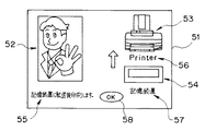
図5は、表示部12の表示例を示す図である。51は、LCD等の表示部12の表示枠である。表示枠51内には、MO4に画像データを記憶した後に、プリンタ3によって画像を印刷することができる旨を示す人の絵52、プリンタを示す絵53、MOを示す絵54、「記憶装置に転送後印刷します。」という文字55、「Printer」の文字56、「記憶装置」の文字57を用いて表示されている。さらに、表示画面中には、「印刷」のコマンドを示すボタン58も含まれている。
【0042】
なお、表示部12において表示が、ユーザが選択した操作に応じて画面が遷移していくような場合は、PC2は、S5において、複数の画面の中から選択された画面毎にその画面を表示するためのプログラムあるいは画面データを送信し、DSC1では、S11及びS12において、選択操作毎に受信したプログラムあるいは画面データに基いて画面表示を行うようにしてもよい。
【0043】
このような表示がDSC1の表示部12においてされているときに、ユーザが予め決められた操作をしたか否かが判断される(S14)。例えば、ユーザが、DSC1に記憶されている画像データをMO4に転送して記憶させた後に、プリンタ3で画像データに基いて画像を印刷する場合は、DSC1の操作部13の1つである矢印キーを操作することによって、表示されているボタン58上にカーソルを移動してボタン58を押す、すなわちボタン58を選択すると、S14でYESとなって、プリンタ3とMO4の制御コマンドに関するデータがPC2へ送信される(S15)。DSC1では、終了操作がなされたか否かが判断され(S16)、終了操作がされたときは、S16でYESとなって、処理は終了する。終了操作がされないときは、処理はS14へ戻る。なお、S16の終了は、1つの画面に基づく制御コマンドに関するデータが送信される毎に終了するようにしてもよいし、接続ケーブル5がDSC1又はプリンタ3から外されたときに終了するようにしてもよい。
【0044】
次に、DSC1からPC2へ制御コマンドに関するデータが送信された場合のPC2の処理を説明する。図6は、PC2が制御コマンドに関するデータを受信して実行する場合の処理の流れの例を示すフローチャートである。
【0045】
まず、PC2は、図4のS13における外部機器制御モードの通知を受信したか否かを判断し(S21)、外部機器制御モードの通知をDSC1から受信すると、S21でYESとなって、PC1は外部機器制御モードに移行する(S22)。PC2は、制御コマンドに関するデータをDSC1から受信したか否かが判断され(S23)、制御コマンドに関するデータをDSC1から受信すると、S23でYESとなって、受信した制御コマンドに関するデータを外部機器制御コマンドに変換、あるいは受信した制御コマンドに関するデータに基づいて外部機器制御コマンドを生成する(S24)。
【0046】
例えば、PC2はDSC1の表示部12に表示されている画面の内容を認識しているのでその画面に対応してユーザが指定した制御コマンドを、PC2は認識することができる。例えば図5の表示がDSC1の表示部12において行われているときに、OKボタン58が選択されたとすると、「MO4に画像データを記憶した後に、プリンタ3によって画像を印刷する」コマンドに関するデータがPC2において受信される。よって、PC2は、MO4に画像データを記憶した後に、プリンタ3によって画像を印刷するように、外部機器制御コマンドを生成し、MO4とプリンタ3に送信する(S25)。その結果、MO4は、DSC1からの画像データを記憶し、その後、プリンタ3が画像データに基いて画像を印刷する。
【0047】
なお、図5では、プリンタ3とMO4が表示され、かつMO4に画像データを記憶した後に、プリンタ3によって画像を印刷する場合の例が示されているが、プリンタ3のみがPC2に接続されており、プリンタ3によって画像を印刷する場合であれば、プリンタ3だけが表示される。
【0048】
また、DSC1の表示部12には、外部機器であるプリンタ3及びMO4の状態が表示される。プリンタ3及びMO4とPC2とは既にデータ通信ができる状態にあり、プリンタ3及びMO4の状態に変化があれば、その状態データがプリンタ3からPC2へ送信されるので、PC2は、外部機器の状態データを常に得ることができる。例えば、プリンタ3にエラーが発生すれば、エラーの内容を示すエラーデータプリンタ3からPC2へ送信され、PC2は、表示部12の画面を変更するプログラムを選択あるいは生成して、DSC1へ送信する。その結果、DSC1においてそのプログラムが実行され、図7に示す画面表示がDSC1の表示部12になされる。
【0049】
図7は、プリンタ3が印刷中であることを示す画面の例を示す図である。図7に示すように、表示枠51中には、プリンタ3の絵61と、プリンタ3に設けられた表示部と同じ表示内容を示す表示枠62と、印刷中であることを示す文字63を含む。従って、ユーザがDSC1において印刷指示をし、プリンタ3において印刷が行われていると、図7に示すような画面が表示部12に表示されるので、ユーザはプリント中であることを知ることができる。
【0050】
また、ユーザは、操作部13のボタンを操作して、表示枠62中のキャンセルボタン64を選択すると、印刷をキャンセルすることができる。この場合も、DSC1からPC2へ印刷キャンセルのコマンドに関するデータが送信され、PC2は、そのデータに基いてプリンタ3に対して印刷キャンセルのコマンドを送信し、その結果、プリンタ3の印刷がキャンセルされる。
【0051】
さらにまた、図7の表示において、プリンタ3の状態を、プリンタ3の表示ランプの絵65を対応した色に変更表示する。例えば、プリンタ3の状態変化に応じて、絵65の色は、印刷可能になれば白色に、印刷中になれば緑色に、エラーになれば赤色に変更表示される。
【0052】
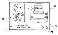
また、プリンタ3において、紙詰まりが発生すると、プリンタ3からPC2へそのエラーが発生したことを示す状態データが送信される。よって、PC2では、紙詰まりが発生したしたことを示す画面のプログラムを生成して、DSC1へ送信する。図8は、紙詰まりを示す画面の例を示す図である。図8において、表示枠51には、紙詰まりをしているプリンタ3の絵71と、その旨を示す絵72と、その旨を示す文字73と、印刷を続行する場合のボタン74を含む。従って、ユーザは、プリンタ3において紙詰まりが発生したことを知ることができる。
【0053】
状態変化の処理とエラー処理の内容を、図9に示す。図9は、PC2による状態変化及びエラーの処理の流れの例を示すフローチャートである。まず、外部機器において状態変化があったか否かが判断される(S31)。PC2とプリンタ3等の間で通信を介して、プリンタ3等は、PC2へ状態変化があったことを通知するためのデータを送信することによって、PC2はこの判断をすることができる。
【0054】
その結果、PC2は、その状態変化に応じた状態変化処理を実行する(S32)。例えば、プリンタ3が正常に印刷中であれば、PC2は、正常に印刷中である旨の情報をプリンタ3から得るので、PC2はその状態を示す図7の画面のプログラムを生成して、DSC1に送信するという処理を実行する。
【0055】
また、外部機器3にエラーが発生したかが判断される(S33)。PC2とプリンタ3等の間で通信を介して、プリンタ3等はPC2へエラーが発生したことを通知するためのデータを送信することによって、PC2はこの判断をすることができる。その結果、PC2はそのエラー処理を実行する(S34)。例えば、プリンタ3において、紙詰まりが発生すれば、PC2は、紙詰まりが発生した旨の情報をプリンタ3から得るので、PC2はその状態を示す図8の画面のプログラムを生成して、DSC1に送信するという処理を実行する。
【0056】
以上のように、印刷エラー等が発生し、その印刷ができない旨の表示等は、PC2あるいはプリンタ3ではなく、DSC1の表示部12においてされる。よって、ユーザがPC等に不慣れであっても、外部機器の問題の発生を認識することができる。
【0057】
なお、以上の例では、図5、図7及び図8に示すように、表示部12に絵、図形等を表示し、その表示を選択することによって、外部機器への制御コマンドを、ユーザが指定できるようになっている。例えば、図5の58、図7の64、図8の74である。しかし、表示された絵等の部分を選択することによって、プリンタ3への制御コマンドを指定するのではなく、DSC1の操作部13のボタン等を操作させることによって、プリンタ3への制御コマンドを指定するようにしてもよい。
【0058】
図10は、DSC1の表示部12に表示される画面の例を示す図である。図10に示すように、PC2からDSC1へ送信されたプログラムによって生成された画面が、DSC1に記憶された画像データを印刷することができる旨を表示しているが、ここでは、プリンタ3に画像を印刷させるときは、DSC1の操作ボタンの1つであるセルフタイマーボタンを押すことを文字81によって、ユーザに示している。このとき、DSC1は外部機器制御モードに設定されているので、DSC1では、セルフタイマーボタンは、プリンタ3へのプリントコマンド指示ボタンとなっている。よって、セルフタイマーボタンが押されると、DSC1はPC2へ印刷指示コマンドのデータを送信する。
【0059】
同様に、図11は、DSC1の表示部12に表示される画面の他の例を示す図である。図11は、絵を用いて、DSC1のどのボタンが印刷指示ボタンであるかを表示する場合の例を示す図である。図11中、DSC1の外観を示す絵91と、DSC1の操作ボタン中、矢印92で示したボタンが、プリントコマンド指示ボタンとなっていることが、絵によって示されている。よって、ユーザが、DSC1の矢印92で指示されたボタンを押すと、DSC1はPC2へ印刷指示コマンドのデータを送信する。なお、矢印で示さないで、対応するボタン部分93が点滅することによって、印刷指示ボタンであることを示すようにしてもよい。
【0060】
以上のように、本実施の形態によれば、PC、プリンタ等に不慣れなユーザであっても、DSCを用いて、プリンタ等を容易に操作することができる。
【0061】
なお、以上の説明は、DSC1と、プリンタ3とMO4との間での処理で説明したが、さらに多くの外部機器が接続されていてもよいし、あるいはDSC1とPC2とプリンタ3のみからなるシステムであってもよい。
【0062】
さらに、以上の説明では、DSCへ送信されるプログラムは、予めPCの記憶部に記憶されている例で説明したが、DSC、プリンタ等の最新の機種にも対応したデータとするために、別途CD−ROM等の記憶媒体から、テーブルデータ及びプログラムを読み込むようにしたり、あるいはインターネットを介して、予め決められたサイトから、テーブルデータ及びプログラムをダウンロードして、PCの記憶部に記憶するようにしてもよい。
【0063】
また、以上の説明は、DSCの記憶する画像データを、プリンタ等の外部機器に出力させる例であるが、DSCではなく、カメラ機能を有する携帯電話であってもよい。すなわち、カメラ機能を有する携帯電話は、携帯電話機能を有するカメラとも言えるからである。
【0064】
なお、PCにおいて実行されるプログラムは、フロッピー(登録商標)ディスク、CD−ROM等の可搬媒体や、ハードディスク等の記憶装置等に、その全体あるいは一部が記録され、あるいは記憶されている。そのプログラムがコンピュータにより読み取られて、動作の全部あるいは一部が実行される。あるいは、そのプログラムの全体あるいは一部を通信ネットワークを介して流通または提供することができる。利用者は、通信ネットワークを介してそのプログラムをダウンロードしてコンピュータにインストールしたり、あるいは記録媒体からコンピュータにインストールすることで、容易に本発明の画像データ制御装置を実現することができる。
【0065】
本発明は、上述した実施の形態に限定されるものではなく、本発明の要旨を変えない範囲において、種々の変更、改変等が可能である。
【0066】
【発明の効果】
以上説明したように、PC等の制御機器に接続されている外部機器同士のフォーマットが異なっていても、これらの機器の整合性を容易に取れるので、機器に不慣れなユーザであっても容易に操作できる。
【0067】
また、PC等の制御機器を直接操作しなくても、PC等の制御機器に接続されている一部の外部機器を操作するだけで、他の外部機器を制御できる。
【図面の簡単な説明】
【図1】本発明の実施の形態に係わる画像データ制御システムの構成を示す構成図である。
【図2】本発明の実施の形態に係わるDSC、PC及びプリンタの構造を示すブロック構成図である。
【図3】DSCをPCに接続したときに、PCで実行される処理の流れの例を示すフローチャートである。
【図4】DSCにおける処理の流れの例を示すフローチャートである。
【図5】DSCの表示部の表示例を示す図である。
【図6】PCが制御コマンドに関するデータを受信して実行する場合の処理の流れの例を示すフローチャートである。
【図7】プリンタが印刷中であることを示す画面の例を示す図である。
【図8】紙詰まりを示す画面の例を示す図である。
【図9】PCによる状態変化及びエラーの処理の流れの例を示すフローチャートである。
【図10】DSCの表示部に表示される画面の例を示す図である。
【図11】DSCの表示部に表示される画面の他の例を示す図である。
【符号の説明】
1・・・デジタルカメラ、2・・・パーソナルコンピュータ、3・・・プリンタ、4・・・光磁気ディスク装置[0001]
TECHNICAL FIELD OF THE INVENTION
The present invention relates to a control system, a control method, a printing system, an image data control device, and a program.
[0002]
[Prior art]
In recent years, digital cameras have been widely used. The digital camera has storage means for recording an image of a subject as digital image data. Generally, image data recorded in a digital camera is printed by a printer connected to a personal computer (hereinafter abbreviated as PC). In this case, the user connects the digital camera to the PC, reads the image data stored in the storage means in the digital camera, and operates the PC to output the read image data to the printer. Issue a print instruction.
[0003]
However, in a method of printing image data of a digital camera by instructing a printer to print from a PC, if the user is unfamiliar with the operation of the PC, the user can easily print the image data stored in the digital camera. Can not. Therefore, an image printing system that automatically acquires image data from a digital camera, creates print data, and executes printing when a digital camera is connected to a PC has been proposed (for example, see Patent Document 1). According to the system, the user can easily print the image data even if the user is unfamiliar with the operation of the PC or the like.
[0004]
In addition, an apparatus capable of performing various settings of a camera using a PC has been proposed (for example, see Patent Document 2). The camera can be remotely controlled by changing the photographing mode and the like from the PC. A technique for detecting print performance of a printer connected to a PC, transmitting a captured image matching the performance to the printer from the PC, and inquiring the printer about information on print performance from the printer to request transmission. Has been proposed.
[0005]
[Patent Document 1]
JP 2001-238156 A (
[0006]
[Patent Document 2]
JP-A-2000-32321 (pages 18 to 22, FIGS. 20 and 24)
[0007]
[Problems to be solved by the invention]
However, in the case of an image printing system that automatically obtains image data from a digital camera, creates print data, and executes printing, the PC, digital camera, and printer must be predetermined. That is, when the PC acquires the image data, the format of the image data stored in the digital camera must be a predetermined format. Further, when the PC creates and executes print data, The processing cannot be executed unless the format is a predetermined format corresponding to the printer connected to the PC.
[0008]
Also, even if the PC uses the technology of remotely controlling the camera, if the user is unfamiliar with the operation of the PC, the printer, etc., the user will not be able to handle external devices such as a printer. It was not easy.
[0009]
Therefore, an object of the present invention is to provide a control system that allows even a user who is unfamiliar with a control device such as a PC or an external device such as a printer to easily obtain consistency of these devices and easily operate the device. I do.
[0010]
[Means for Solving the Problems]
The control system of the present invention has a receiving unit for receiving a program, a first external device operable based on the program received by the receiving unit, and the first external device based on the program received by the first external device. When it is determined that the second external device operable in association with the command output from the first external device and the first and second external devices are controllably connected, A control device for selecting a specific program for causing the first device and the second external device to operate in relation to each other, and for transmitting the selected specific program to the first external device. Then, the second external device is controlled by a command output from the first external device.
[0011]
BEST MODE FOR CARRYING OUT THE INVENTION
Hereinafter, embodiments of the present invention will be described with reference to the drawings.
[0012]
First, a configuration of a system according to the present embodiment will be described with reference to FIG. FIG. 1 is a configuration diagram showing a configuration of an image data control system according to the present embodiment.
[0013]
In FIG. 1,
[0014]
The PC 2 and the DSC 1 are connected by a
[0015]
FIG. 2 is a block diagram showing the structure of the
[0016]
The
[0017]
The
[0018]
The
[0019]
The
[0020]
When receiving a control command from the
[0021]
Although the configuration of the MO4 is omitted here, the configuration is the same as the configuration of a normal magneto-optical disk device.
[0022]
Hereinafter, an example of data communication between the
[0023]
The
[0024]
As will be described later, according to the present embodiment, the user operates the
[0025]
FIG. 3 is a flowchart illustrating an example of the flow of processing executed by the
[0026]
First, the
[0027]
First, in S2, the DSC is confirmed. In the confirmation of the DSC, the type of the DSC connected via the USB, that is, the manufacturer name, the model number, the firmware version, and the like are confirmed. Note that the DSC may be confirmed using the function of the USB interface which is the physical layer of the communication interface. However, when the
[0028]
Next, the
[0029]
Then, as a result of the processing in S2 and S3, it is determined whether or not the
[0030]
The determination in S4 is made based on, for example, whether or not a program corresponding to the type of DSC and the type of printer confirmed in S2 and S3 is prepared in advance. Programs corresponding to the type of DSC and the type of printer will be described later.
[0031]
Next, the
[0032]
The selected program is transmitted to the
[0033]
Further, the program must be adapted to the performance, function, configuration, etc. of the
[0034]
The selection of a suitable program may be made based on table data corresponding to the functions of the
[0035]
Specifically, the
[0036]
Further, the
[0037]
PC2 transmits the selected program to DSC1 (S6). The selected program displays a screen for allowing the user to control the
[0038]
FIG. 4 is a flowchart illustrating an example of the flow of processing in DSC1. First, the
[0039]
When the
[0040]
When the program received in S12 is executed, a screen generated by the program is displayed on the
[0041]
FIG. 5 is a diagram illustrating a display example of the
[0042]
When the display is changed on the
[0043]
When such a display is performed on the
[0044]
Next, a process of the
[0045]
First, the
[0046]
For example, since the
[0047]
FIG. 5 shows an example in which the
[0048]
The
[0049]
FIG. 7 is a diagram illustrating an example of a screen indicating that the
[0050]
Further, the user can cancel the printing by operating the button of the
[0051]
Further, in the display of FIG. 7, the state of the
[0052]
When a paper jam occurs in the
[0053]
FIG. 9 shows the contents of the state change processing and the error processing. FIG. 9 is a flowchart illustrating an example of the flow of processing of a state change and an error by the
[0054]
As a result, the
[0055]
Further, it is determined whether an error has occurred in the external device 3 (S33). Through communication between the
[0056]
As described above, a display indicating that a printing error or the like has occurred and the printing cannot be performed is displayed on the
[0057]
In the above example, as shown in FIG. 5, FIG. 7, and FIG. 8, a picture, a graphic, or the like is displayed on the
[0058]
FIG. 10 is a diagram illustrating an example of a screen displayed on the
[0059]
Similarly, FIG. 11 is a diagram illustrating another example of a screen displayed on the
[0060]
As described above, according to the present embodiment, even a user unfamiliar with a PC, a printer, and the like can easily operate the printer and the like using the DSC.
[0061]
In the above description, the processing between the
[0062]
Furthermore, in the above description, the example in which the program transmitted to the DSC is stored in the storage unit of the PC in advance has been described. The table data and the program are read from a storage medium such as a CD-ROM, or the table data and the program are downloaded from a predetermined site via the Internet and stored in the storage unit of the PC. May be.
[0063]
In the above description, the image data stored in the DSC is output to an external device such as a printer. However, a mobile phone having a camera function may be used instead of the DSC. That is, a mobile phone having a camera function can be said to be a camera having a mobile phone function.
[0064]
The program executed by the PC is entirely or partially recorded or stored in a portable medium such as a floppy (registered trademark) disk, a CD-ROM, or a storage device such as a hard disk. The program is read by the computer, and all or part of the operation is executed. Alternatively, the whole or a part of the program can be distributed or provided via a communication network. The user can easily realize the image data control device of the present invention by downloading the program via a communication network and installing the program on a computer, or installing the program on a computer from a recording medium.
[0065]
The present invention is not limited to the above-described embodiment, and various changes and modifications can be made without departing from the spirit of the present invention.
[0066]
【The invention's effect】
As described above, even if the formats of the external devices connected to the control device such as a PC are different, the consistency of these devices can be easily obtained. Can operate.
[0067]
Further, other external devices can be controlled only by operating some external devices connected to the control device such as a PC without directly operating the control device such as a PC.
[Brief description of the drawings]
FIG. 1 is a configuration diagram showing a configuration of an image data control system according to an embodiment of the present invention.
FIG. 2 is a block diagram showing a structure of a DSC, a PC, and a printer according to the embodiment of the present invention.
FIG. 3 is a flowchart illustrating an example of the flow of processing executed by the PC when the DSC is connected to the PC.
FIG. 4 is a flowchart illustrating an example of the flow of processing in a DSC.
FIG. 5 is a diagram illustrating a display example of a display unit of a DSC.
FIG. 6 is a flowchart illustrating an example of a processing flow when a PC receives and executes data related to a control command.
FIG. 7 illustrates an example of a screen indicating that the printer is printing.
FIG. 8 is a diagram illustrating an example of a screen indicating a paper jam.
FIG. 9 is a flowchart illustrating an example of a flow of a status change and error process by the PC.
FIG. 10 is a diagram illustrating an example of a screen displayed on a display unit of a DSC.
FIG. 11 is a diagram showing another example of a screen displayed on the display unit of the DSC.
[Explanation of symbols]
DESCRIPTION OF
Claims (7)
上記第1の外部機器が受信したプログラムに基づいて上記第1の外部機器から出力されたコマンドに関連して動作可能な第2の外部機器と、
上記第1及び第2の外部機器が制御可能に接続されていると判定された際に、上記第1の機器と上記第2の外部機器とが互いに関連して動作するための特定プログラムを選択するとともに、選択された特定プログラムを上記第1の外部機器へ送信する制御機器と、
からなる制御システムであって、
上記第1の外部機器から出力されたコマンドによって、上記第2の外部機器を制御するようにしたことを特徴とする制御システム。A first external device having receiving means for receiving the program, and operable based on the program received by the receiving means;
A second external device operable in association with a command output from the first external device based on a program received by the first external device;
When it is determined that the first and second external devices are controllably connected, a specific program for operating the first device and the second external device in association with each other is selected. And a control device for transmitting the selected specific program to the first external device;
A control system comprising:
A control system wherein the second external device is controlled by a command output from the first external device.
上記制御機器は、
上記カメラと上記プリンタとが制御可能に接続されているか否かを判定する手段と、
上記カメラと上記プリンタとが制御可能に接続されている判定された際に、上記カメラ及び上記プリンタに固有の動作プログラムを生成または選択する手段と、
上記生成または選択された動作プログラムを上記カメラへ送信するプログラム送信手段と、
を有し、
上記カメラは、
上記制御機器から送信されてきた上記動作プログラムを受信する受信手段と、
上記受信手段で受信した上記動作プログラムを実行する実行手段と、
上記カメラを制御するための入力を行う操作部材と、
上記受信手段で受信した上記動作プログラムを実行された状態で上記操作部材が操作された際に、上記カメラを制御するための入力を、上記プリンタを制御するための入力に変更する手段と、
上記変更された入力の内容を上記プリンタ用の指令として上記制御機器へ出力する手段と、
を有していることを特徴とする印刷システム。In a printing system in which a camera and a printer are connected via a control device,
The control device is
Means for determining whether the camera and the printer are controllably connected,
Means for generating or selecting an operation program unique to the camera and the printer, when it is determined that the camera and the printer are controllably connected,
Program transmission means for transmitting the generated or selected operation program to the camera,
Has,
The above camera is
Receiving means for receiving the operation program transmitted from the control device;
Executing means for executing the operation program received by the receiving means;
An operation member for performing input for controlling the camera,
Means for changing an input for controlling the camera to an input for controlling the printer when the operating member is operated in a state where the operation program received by the receiving means is executed;
Means for outputting the content of the changed input to the control device as a command for the printer,
A printing system comprising:
上記プログラムは、上記プリンタの実行に関するコマンドをユーザに選択させるための表示を、上記表示部に行わせ、かつ、上記ユーザによって選択された上記コマンドに関するデータを、上記制御機器へ送信させるプログラムであることを特徴とする請求項2に記載の印刷システム。The camera has a display unit,
The program is a program that causes the display unit to display a command for allowing a user to select a command related to execution of the printer, and transmits data related to the command selected by the user to the control device. 3. The printing system according to claim 2, wherein:
上記プログラムは、上記プリンタの状態に関する状態情報を、上記表示部に表示させるプログラムであることを特徴とする請求項2に記載の印刷システム。The camera has a display unit,
The printing system according to claim 2, wherein the program is a program for displaying status information on a status of the printer on the display unit.
上記第1の機器の画像データを上記第2の機器が処理可能に、上記第1の機器と上記第2の機器とが接続されているか否かを判定する判定部と、
上記第2の機器の制御コマンドに関するデータを生成するためのプログラムを生成又は選択するプログラム生成部と、
上記プログラムに基いて生成された上記データを受信する受信部と、
上記受信部が受信した上記データに基いて、上記第2の機器の上記制御コマンドを生成する制御コマンド生成部とを有することを特徴とする画像データ制御装置。A control device in which a first device and a second device are connected,
A determination unit configured to determine whether the first device and the second device are connected so that the second device can process image data of the first device;
A program generation unit that generates or selects a program for generating data related to the control command of the second device;
A receiving unit that receives the data generated based on the program,
An image data control device, comprising: a control command generation unit configured to generate the control command of the second device based on the data received by the reception unit.
上記制御機器に接続された第1及び第2の外部機器を認識するステップと、
上記認識された第1及び第2の外部機器が互いに関連して動作するための特定プログラムであって、上記第1の外部機器からの出力で上記第2の外部機器を制御する制御プログラムを選択するステップと、
上記選択された制御プログラムを上記第1の外部機器へ送信するステップと、
送信された上記制御プログラムを実行することにより、上記第1の外部機器からの出力を上記第2の外部機器を制御するための指令に変換するステップと、
を上記制御機器のコンピュータに実行させるプログラム。A program executed on a control device to which a first external device and a second external device are connected,
Recognizing first and second external devices connected to the control device;
A specific program for causing the recognized first and second external devices to operate in association with each other, and selecting a control program for controlling the second external device with an output from the first external device. Steps to
Transmitting the selected control program to the first external device;
Converting the output from the first external device into a command for controlling the second external device by executing the transmitted control program;
For causing a computer of the control device to execute the above.
上記第1の外部機器及び第2の外部機器の接続を認識し、
上記第1の外部機器及び第2の外部機器の種類を認識し、
上記第1の外部機器及び第2の外部機器が互いに関連して動作するための特定プログラムであって、上記第1の外部機器に設けられた操作部材から出力される指令内容を変更するプログラムを選択し、
選択された上記プログラムを上記第1の外部機器へ送信し、
送信された上記プログラムを実行することにより上記第1の外部機器に設けられた上記操作部材から出力される出力を上記第2の外部機器を制御するための指令を出力となるように信号の定義を変更し、
上記第1の外部機器に設けられた操作部材からの出力を、上記第2の外部機器を制御するための第1の制御命令として上記制御機器へ出力し、
上記制御機器で上記第1の制御命令を解析して上記第2の外部機器を制御する第2の制御命令を第2の外部機器へ出力し、
上記制御機器を介して、上記第1の外部機器で上記第2の外部機器を制御する制御方法。A control method of a system in which a first external device and a second external device are connected via a control device,
Recognizing the connection between the first external device and the second external device,
Recognizing the types of the first external device and the second external device,
A specific program for causing the first external device and the second external device to operate in association with each other, and a program for changing a command content output from an operation member provided in the first external device. Selected,
Transmitting the selected program to the first external device;
By executing the transmitted program, a signal is defined so that an output output from the operating member provided in the first external device becomes a command for controlling the second external device. Change
Outputting an output from an operating member provided to the first external device to the control device as a first control command for controlling the second external device;
The control device analyzes the first control command and outputs a second control command for controlling the second external device to a second external device,
A control method in which the first external device controls the second external device via the control device.
Priority Applications (3)
| Application Number | Priority Date | Filing Date | Title |
|---|---|---|---|
| JP2003129476A JP2004334531A (en) | 2003-05-07 | 2003-05-07 | Control system, control method, print system, image data controller, and program |
| US10/830,654 US20040223060A1 (en) | 2003-05-07 | 2004-04-23 | Control system, control method, printing system, and image data control apparatus and program |
| CNB2004100422353A CN100508557C (en) | 2003-05-07 | 2004-05-08 | Control system, control method, printing system, and image data control apparatus and program |
Applications Claiming Priority (1)
| Application Number | Priority Date | Filing Date | Title |
|---|---|---|---|
| JP2003129476A JP2004334531A (en) | 2003-05-07 | 2003-05-07 | Control system, control method, print system, image data controller, and program |
Publications (1)
| Publication Number | Publication Date |
|---|---|
| JP2004334531A true JP2004334531A (en) | 2004-11-25 |
Family
ID=33410509
Family Applications (1)
| Application Number | Title | Priority Date | Filing Date |
|---|---|---|---|
| JP2003129476A Withdrawn JP2004334531A (en) | 2003-05-07 | 2003-05-07 | Control system, control method, print system, image data controller, and program |
Country Status (3)
| Country | Link |
|---|---|
| US (1) | US20040223060A1 (en) |
| JP (1) | JP2004334531A (en) |
| CN (1) | CN100508557C (en) |
Cited By (2)
| Publication number | Priority date | Publication date | Assignee | Title |
|---|---|---|---|---|
| JP2007235723A (en) * | 2006-03-02 | 2007-09-13 | Canon Inc | Image transmitter and imaging apparatus |
| CN102055868A (en) * | 2009-10-30 | 2011-05-11 | 京瓷美达株式会社 | Information processing device, screen data generation method, operational control method, electrical device, and operational control system |
Families Citing this family (18)
| Publication number | Priority date | Publication date | Assignee | Title |
|---|---|---|---|---|
| US7792970B2 (en) * | 2005-06-17 | 2010-09-07 | Fotonation Vision Limited | Method for establishing a paired connection between media devices |
| US7685341B2 (en) * | 2005-05-06 | 2010-03-23 | Fotonation Vision Limited | Remote control apparatus for consumer electronic appliances |
| US7777779B2 (en) * | 2003-09-10 | 2010-08-17 | Olympus Corporation | Photographing apparatus, control method for lens barrel of photographing apparatus, printer, control method for printer, and printing system |
| JP2005316625A (en) * | 2004-04-28 | 2005-11-10 | Fuji Photo Film Co Ltd | Image data communication system and image server and portable electronic equipment and their control method |
| JP4484625B2 (en) * | 2004-08-10 | 2010-06-16 | キヤノン株式会社 | COMMUNICATION DEVICE, FILE TRANSFER SYSTEM, AND COMMUNICATION DEVICE CONTROL METHOD |
| JP2006056039A (en) * | 2004-08-17 | 2006-03-02 | Funai Electric Co Ltd | Photo-direct printer |
| JP4353037B2 (en) * | 2004-09-21 | 2009-10-28 | 船井電機株式会社 | Direct print system |
| JP4561272B2 (en) * | 2004-09-21 | 2010-10-13 | 船井電機株式会社 | Direct print system |
| US9910341B2 (en) | 2005-01-31 | 2018-03-06 | The Invention Science Fund I, Llc | Shared image device designation |
| US9489717B2 (en) | 2005-01-31 | 2016-11-08 | Invention Science Fund I, Llc | Shared image device |
| US10003762B2 (en) | 2005-04-26 | 2018-06-19 | Invention Science Fund I, Llc | Shared image devices |
| US9819490B2 (en) * | 2005-05-04 | 2017-11-14 | Invention Science Fund I, Llc | Regional proximity for shared image device(s) |
| US7694048B2 (en) * | 2005-05-06 | 2010-04-06 | Fotonation Vision Limited | Remote control apparatus for printer appliances |
| JP5020517B2 (en) * | 2006-02-02 | 2012-09-05 | キヤノン株式会社 | Printing system, printing apparatus, imaging apparatus, and control method |
| JP2008146181A (en) * | 2006-12-06 | 2008-06-26 | Canon Inc | Information processing method and information processing system |
| EP2410414B1 (en) * | 2010-07-16 | 2019-10-30 | BlackBerry Limited | Media module control |
| TWI544337B (en) * | 2012-10-25 | 2016-08-01 | 緯創資通股份有限公司 | Dual-operating-system architecture for sharing usb devices, and method for sharing usb devices in a dual-operating-system architecture |
| JP6493466B2 (en) * | 2017-07-28 | 2019-04-03 | 富士ゼロックス株式会社 | Information processing apparatus and program |
Family Cites Families (14)
| Publication number | Priority date | Publication date | Assignee | Title |
|---|---|---|---|---|
| DE19645716A1 (en) * | 1995-11-06 | 1997-05-07 | Ricoh Kk | Digital individual image camera with image data transaction function |
| US7212229B2 (en) * | 1997-04-04 | 2007-05-01 | Eastman Kodak Company | Digital camera providing image processing for an attachable printer |
| JPH10341396A (en) * | 1997-04-09 | 1998-12-22 | Seiko Epson Corp | Function-adding method for digital camera and digital camera |
| JPH1173247A (en) * | 1997-06-27 | 1999-03-16 | Canon Inc | I/o card and electronic equipment and electronic system and method for rising electronic equipment |
| TW502172B (en) * | 1998-10-26 | 2002-09-11 | Winbond Electronics Corp | Digital camera to printer conversion device with USB structure |
| JP2000307594A (en) * | 1999-04-21 | 2000-11-02 | Nec Corp | Optimal processing distributing system for av device function |
| JP4046897B2 (en) * | 1999-06-30 | 2008-02-13 | キヤノン株式会社 | Image input apparatus and control method thereof |
| US6957437B1 (en) * | 1999-12-23 | 2005-10-18 | Intel Corporation | Selecting a device driver for a peripheral device adapted to operate on a network and simplifying secondary printer installation |
| JP2003338972A (en) * | 2001-09-12 | 2003-11-28 | Fuji Photo Film Co Ltd | Image processing system, imaging unit, apparatus and method for processing image and program |
| US20030227554A1 (en) * | 2002-04-26 | 2003-12-11 | Nikon Corporation | Digital camera system |
| US20030220988A1 (en) * | 2002-05-22 | 2003-11-27 | Hymel James A. | Method and electronic device for establishing an interface to control an accessory device |
| JP4420647B2 (en) * | 2003-04-15 | 2010-02-24 | シャープ株式会社 | Control system |
| US20040221146A1 (en) * | 2003-04-30 | 2004-11-04 | International Business Machines Corporation | Build time dynamic installation of drivers on cloned systems |
| US8176503B2 (en) * | 2004-01-27 | 2012-05-08 | Hewlett-Packard Development Company, L.P. | Device driver selection |
-
2003
- 2003-05-07 JP JP2003129476A patent/JP2004334531A/en not_active Withdrawn
-
2004
- 2004-04-23 US US10/830,654 patent/US20040223060A1/en not_active Abandoned
- 2004-05-08 CN CNB2004100422353A patent/CN100508557C/en not_active Expired - Fee Related
Cited By (3)
| Publication number | Priority date | Publication date | Assignee | Title |
|---|---|---|---|---|
| JP2007235723A (en) * | 2006-03-02 | 2007-09-13 | Canon Inc | Image transmitter and imaging apparatus |
| CN102055868A (en) * | 2009-10-30 | 2011-05-11 | 京瓷美达株式会社 | Information processing device, screen data generation method, operational control method, electrical device, and operational control system |
| US8873073B2 (en) | 2009-10-30 | 2014-10-28 | Kyocera Mita Corporation | Information processing device, computer-readable recording medium on which operational control program is recorded, electrical device, and operational control system |
Also Published As
| Publication number | Publication date |
|---|---|
| CN100508557C (en) | 2009-07-01 |
| CN1551618A (en) | 2004-12-01 |
| US20040223060A1 (en) | 2004-11-11 |
Similar Documents
| Publication | Publication Date | Title |
|---|---|---|
| JP2004334531A (en) | Control system, control method, print system, image data controller, and program | |
| EP1784979B1 (en) | Portable communication apparatus, print system, and control method thereof | |
| KR100663209B1 (en) | Printing system, control method therefor, and photo-direct printing apparatus | |
| JP3530847B2 (en) | Printing apparatus, control method therefor, and printing system | |
| US20150036002A1 (en) | Configuring apparatus, image output apparatus, methods of controlling the same, and program | |
| KR100619150B1 (en) | Image transmission/reception system, image transmission apparatus and image reception apparatus | |
| JP2004032783A (en) | Method and device for printing picture image printing process and instrument | |
| WO2004090711A1 (en) | System and method for outputting images | |
| US8144343B2 (en) | Printing apparatus and an image supply device using picture transfer protocol having a function which checks attribute information of a file object managed in the image supply device | |
| JP4321802B2 (en) | Printing system, printer, and printer control device | |
| JP3625345B2 (en) | Image processing system | |
| JP2004072350A (en) | Digital camera and printer | |
| JP7020822B2 (en) | System, image pickup device, information processing device, control method, and program | |
| JP5972115B2 (en) | Imaging apparatus, control method thereof, and program | |
| JP2005006012A (en) | Image input unit, image output unit and image output system | |
| JP5127597B2 (en) | Image display system, image display apparatus and control method thereof, image processing apparatus and control method thereof | |
| JP2011004244A (en) | Image display system, image management device, image display, and program | |
| JP2006168079A (en) | Recording system and method for recording it, image feeding apparatus and method for controlling it, recording apparatus and method for controlling it, program, and storing medium | |
| JP2002204414A (en) | Data transfer method and image photographing device | |
| JP3854981B2 (en) | Camera, printer, and control method thereof | |
| JP5379425B2 (en) | Image output apparatus and control method thereof | |
| JP2006005760A (en) | Recording device, imaging device, and printing system | |
| JP2011029855A (en) | Image processing apparatus and method for controlling the same, and computer program | |
| JP2005004457A (en) | Image output system, image output device, and terminal device | |
| JP2004328270A (en) | Image processing apparatus, imaging apparatus, control method for them, and program |
Legal Events
| Date | Code | Title | Description |
|---|---|---|---|
| A300 | Application deemed to be withdrawn because no request for examination was validly filed |
Free format text: JAPANESE INTERMEDIATE CODE: A300 Effective date: 20060801 |