JP2004321320A - Washing machine - Google Patents
Washing machine Download PDFInfo
- Publication number
- JP2004321320A JP2004321320A JP2003117447A JP2003117447A JP2004321320A JP 2004321320 A JP2004321320 A JP 2004321320A JP 2003117447 A JP2003117447 A JP 2003117447A JP 2003117447 A JP2003117447 A JP 2003117447A JP 2004321320 A JP2004321320 A JP 2004321320A
- Authority
- JP
- Japan
- Prior art keywords
- water
- laundry
- metal ion
- drum
- washing machine
- Prior art date
- Legal status (The legal status is an assumption and is not a legal conclusion. Google has not performed a legal analysis and makes no representation as to the accuracy of the status listed.)
- Pending
Links
Images


Classifications
-
- D—TEXTILES; PAPER
- D06—TREATMENT OF TEXTILES OR THE LIKE; LAUNDERING; FLEXIBLE MATERIALS NOT OTHERWISE PROVIDED FOR
- D06F—LAUNDERING, DRYING, IRONING, PRESSING OR FOLDING TEXTILE ARTICLES
- D06F37/00—Details specific to washing machines covered by groups D06F21/00 - D06F25/00
- D06F37/20—Mountings, e.g. resilient mountings, for the rotary receptacle, motor, tub or casing; Preventing or damping vibrations
- D06F37/22—Mountings, e.g. resilient mountings, for the rotary receptacle, motor, tub or casing; Preventing or damping vibrations in machines with a receptacle rotating or oscillating about a horizontal axis
- D06F37/225—Damping vibrations by displacing, supplying or ejecting a material, e.g. liquid, into or from counterbalancing pockets
-
- D—TEXTILES; PAPER
- D06—TREATMENT OF TEXTILES OR THE LIKE; LAUNDERING; FLEXIBLE MATERIALS NOT OTHERWISE PROVIDED FOR
- D06F—LAUNDERING, DRYING, IRONING, PRESSING OR FOLDING TEXTILE ARTICLES
- D06F33/00—Control of operations performed in washing machines or washer-dryers
- D06F33/30—Control of washing machines characterised by the purpose or target of the control
- D06F33/32—Control of operational steps, e.g. optimisation or improvement of operational steps depending on the condition of the laundry
- D06F33/40—Control of operational steps, e.g. optimisation or improvement of operational steps depending on the condition of the laundry of centrifugal separation of water from the laundry
-
- D—TEXTILES; PAPER
- D06—TREATMENT OF TEXTILES OR THE LIKE; LAUNDERING; FLEXIBLE MATERIALS NOT OTHERWISE PROVIDED FOR
- D06F—LAUNDERING, DRYING, IRONING, PRESSING OR FOLDING TEXTILE ARTICLES
- D06F33/00—Control of operations performed in washing machines or washer-dryers
- D06F33/30—Control of washing machines characterised by the purpose or target of the control
- D06F33/48—Preventing or reducing imbalance or noise
-
- D—TEXTILES; PAPER
- D06—TREATMENT OF TEXTILES OR THE LIKE; LAUNDERING; FLEXIBLE MATERIALS NOT OTHERWISE PROVIDED FOR
- D06F—LAUNDERING, DRYING, IRONING, PRESSING OR FOLDING TEXTILE ARTICLES
- D06F34/00—Details of control systems for washing machines, washer-dryers or laundry dryers
- D06F34/14—Arrangements for detecting or measuring specific parameters
- D06F34/16—Imbalance
-
- D—TEXTILES; PAPER
- D06—TREATMENT OF TEXTILES OR THE LIKE; LAUNDERING; FLEXIBLE MATERIALS NOT OTHERWISE PROVIDED FOR
- D06F—LAUNDERING, DRYING, IRONING, PRESSING OR FOLDING TEXTILE ARTICLES
- D06F37/00—Details specific to washing machines covered by groups D06F21/00 - D06F25/00
- D06F37/42—Safety arrangements, e.g. for stopping rotation of the receptacle upon opening of the casing door
-
- D—TEXTILES; PAPER
- D06—TREATMENT OF TEXTILES OR THE LIKE; LAUNDERING; FLEXIBLE MATERIALS NOT OTHERWISE PROVIDED FOR
- D06F—LAUNDERING, DRYING, IRONING, PRESSING OR FOLDING TEXTILE ARTICLES
- D06F39/00—Details of washing machines not specific to a single type of machines covered by groups D06F9/00 - D06F27/00
- D06F39/007—Arrangements of water softeners
-
- D—TEXTILES; PAPER
- D06—TREATMENT OF TEXTILES OR THE LIKE; LAUNDERING; FLEXIBLE MATERIALS NOT OTHERWISE PROVIDED FOR
- D06F—LAUNDERING, DRYING, IRONING, PRESSING OR FOLDING TEXTILE ARTICLES
- D06F2103/00—Parameters monitored or detected for the control of domestic laundry washing machines, washer-dryers or laundry dryers
- D06F2103/26—Unbalance; Noise level
-
- D—TEXTILES; PAPER
- D06—TREATMENT OF TEXTILES OR THE LIKE; LAUNDERING; FLEXIBLE MATERIALS NOT OTHERWISE PROVIDED FOR
- D06F—LAUNDERING, DRYING, IRONING, PRESSING OR FOLDING TEXTILE ARTICLES
- D06F2105/00—Systems or parameters controlled or affected by the control systems of washing machines, washer-dryers or laundry dryers
- D06F2105/52—Changing sequence of operational steps; Carrying out additional operational steps; Modifying operational steps, e.g. by extending duration of steps
-
- D—TEXTILES; PAPER
- D06—TREATMENT OF TEXTILES OR THE LIKE; LAUNDERING; FLEXIBLE MATERIALS NOT OTHERWISE PROVIDED FOR
- D06F—LAUNDERING, DRYING, IRONING, PRESSING OR FOLDING TEXTILE ARTICLES
- D06F2105/00—Systems or parameters controlled or affected by the control systems of washing machines, washer-dryers or laundry dryers
- D06F2105/56—Remaining operation time; Remaining operational cycles
Abstract
Description
【0001】
【発明の属する技術分野】
本発明は、イオン溶出手段から金属イオン添加水を収容槽(ドラムまたは洗濯槽)に供給し、収容槽内に収容される洗濯物に対して抗菌処理を行う洗濯機に関するものであり、特に、脱水回転時の収容槽のアンバランスを修正する洗濯機に関するものである。
【0002】
【従来の技術】
洗濯機で洗濯物を洗濯する際、水(特に、すすぎ水)に仕上物質を加えることが良く行われる。仕上物質として一般的なのは、柔軟剤やのり剤である。これに加え、最近では、洗濯物に抗菌性を持たせる仕上処理のニーズが高まっている。
【0003】
洗濯物は、衛生上の観点からは天日干しをすることが望ましい。しかしながら近年では、女性就労率の向上や核家族化の進行により、日中は家に誰もいないという家庭が増えている。このような家庭では、室内干しにたよらざるを得ない。また、日中、誰かが在宅している家庭にあっても、雨天の折りは室内干しをすることになる。
【0004】
室内干しの場合、天日干しに比べ、洗濯物に細菌やカビが繁殖しやすくなる。梅雨時のような高湿時や低温時など、洗濯物の乾燥に時間がかかる場合には、この傾向は顕著である。また、繁殖状況によっては、洗濯物が異臭を放つときもある。
【0005】
また、最近では節約意識が高まり、入浴後の風呂水を洗濯に再利用する家庭が多くなっている。ところが、一晩置いた風呂水は、細菌が増加しており、この細菌が洗濯物に付着してさらに繁殖し、異臭の原因となるという問題も発生している。
【0006】
このため、日常的に室内干しを余儀なくされる家庭、あるいは風呂水を洗濯に再利用する家庭では、細菌やカビの繁殖を抑制するため、布類に抗菌処理を施したいという要請が強い。
【0007】
一方、最近では、繊維に抗菌防臭加工や制菌加工を施した衣類も多くなっている。しかしながら、家庭内の繊維製品をすべて抗菌防臭加工済みのもので揃えるのは困難である。また、抗菌防臭加工の効果は、洗濯を重ねるにつれ落ちて行く。
【0008】
そこで、洗濯の都度、洗濯物を抗菌処理しようという考えが生まれた。例えば特許文献1には、銀イオン、銅イオンなど殺菌力を有する金属イオンを発生するイオン発生機器を装備した電気洗濯機が記載されている。特許文献2には、洗浄水に銀イオンを添加する銀イオン添加ユニットを具備した洗濯機が記載されている。特に、特許文献2の洗濯機では、水に3〜50ppb(part per billion)の濃度で銀イオンを添加して洗濯物に抗菌性を付与することとしている。
【0009】
【特許文献1】
実開平5−74487号公報(1993年10月12日公開)
【特許文献2】
特開2001−276484号公報(2001年10月9日公開)
【0010】
【発明が解決しようとする課題】
ところで、上記した特許文献1・2の洗濯機は、いずれも、回転軸が鉛直方向となるように洗濯槽が配置された、いわゆる縦型の洗濯機(縦型洗)に関するものである。しかし、近年では、回転軸が鉛直方向に対して交差するようにドラムが配置された、いわゆる横型の洗濯機(ドラム洗)も開発されている。
【0011】
ここで、縦型の洗濯機では、洗濯槽の回転軸が鉛直方向に沿っているため、洗濯物に作用する重力は、回転軸に平行な方向となる。この場合、洗濯槽内での偏りが起こりにくく、洗濯物の重心が回転軸上になりやすい。したがって、アンバランスも発生しにくい。なお、アンバランスとは、洗濯物が洗濯槽内で偏って配置されることにより、脱水立ち上げ時にうまく回転バランスがとれず、それに続く脱水工程で洗濯槽や洗濯機本体が大きく振動する現象を言う。また、縦型の洗濯機では、洗濯槽の重心が、鉛直方向である回転軸上にあり、その回転軸はモータの真上にある。そのため、洗濯槽の荷重をモータ部で支えることが可能である。
【0012】
これに対して、横型の洗濯機では、回転軸が鉛直方向にないため、洗濯物に作用する重力が、回転軸の方向とは異なる。つまり、ドラムの静止時には、洗濯物がドラムの下部に溜まるが、その状態では、洗濯物の重心は回転軸上にはない。ドラムが回転し、洗濯物に遠心力が働けば、洗濯物はドラムの周囲方向に押し付けられるが、それが均一にならなければ、アンバランスとなる。したがって、回転軸が鉛直方向でない横型の洗濯機では、その構造上、アンバランス発生頻度が非常に高い。
【0013】
そこで、このようなアンバランスを修正することが必要となるが、この修正方法としては、ドラム内に水を入れて撹拌し、洗濯物の配置を少し変えることが一般的である。しかし、ドラム内に水を入れるだけでは、脱水工程の前工程で洗濯物に付着させた金属が失われるため、せっかく行った抗菌処理の効果を保持することができないという問題が生ずる。このような問題は、縦型の洗濯機においてアンバランスが発生した場合でも、同様に言えることである。
【0014】
本発明は、上記の問題点を解決するためになされたものであり、その目的は、洗濯物に付与された金属イオンによる抗菌効果を失わせることなく、脱水回転時の収容槽のアンバランス修正を行うことができる洗濯機を提供することにある。
【0015】
【課題を解決するための手段】
本発明の洗濯機では、イオン溶出手段から収容槽に供給される金属イオン添加水の供給後に実行される上記収容槽の脱水回転時に、検知手段が上記収容槽のアンバランスを検知した場合に、アンバランス修正手段が、上記金属イオン添加水の非供給時におけるアンバランス検知時とは異なる処理を実行することにより、上記アンバランスを修正する。
【0016】
ここで、金属イオン添加水の非供給時におけるアンバランス修正としては、例えば、収容槽に水(例えば水道水)を供給して洗濯物を攪拌する処理が挙げられる。したがって、これとは異なる処理としては、イオン溶出手段にて得られる金属イオン添加水を収容槽に供給して攪拌を行うバランス修正すすぎを考えることができる。
【0017】
このように、金属イオン添加水の供給後に実行される上記収容槽の脱水回転時に、検知手段が上記収容槽のアンバランスを検知したときには、上記金属イオン添加水の供給という、通常の水道水を供給する処理とは異なる処理を実行することにより、先の金属イオン添加水の供給による抗菌処理にて洗濯物に付与された金属イオンが洗い流されたとしても、後の金属イオン添加水の供給により、その洗い流された分を確実に補うことができる。したがって、先の抗菌処理にて洗濯物に付与された抗菌効果を失うことなく、アンバランス修正を行うことができる。つまり、洗濯物に対する抗菌処理の実効性を担保しながら、アンバランス修正を行うことができる。
【0018】
また、上記アンバランス修正手段は、上記バランス修正すすぎにおける上記収容槽への上記金属イオン添加水の供給量を、それ以前の工程における上記金属イオン添加水の供給量よりも少なくする制御を行ってもよい。先の金属イオン添加水の供給工程(例えばすすぎ工程)にて、洗濯物における抗菌効果を発揮させるのに必要な量の金属イオンは既に供給済みであるので、後のバランス修正すすぎにて、洗い流される分を考慮したとしても、抗菌効果を発揮させるのに必要な量の金属イオンを一から供給する必要がない。これにより、バランス修正すすぎにて、洗濯物の抗菌処理に供されずにそのまま洗い流されてしまい、無駄な金属イオンが出現するのを抑えることができる。
【0019】
また、上記アンバランス修正手段は、上記バランス修正すすぎにおける上記収容槽への上記金属イオン添加水の金属イオン濃度を、それ以前の工程における上記金属イオン添加水の金属イオン濃度よりも少なくする制御を行っても、上記と同様の効果を得ることができる。
【0020】
【発明の実施の形態】
本発明の実施の一形態について、図1ないし図14に基づいて説明すれば、以下の通りである。
【0021】
(1.洗濯機の構成)
図1は、本実施形態に係る横ドラム式洗濯機601の外観斜視図を示しており、図2は、横ドラム式(横型)洗濯機601の垂直断面図を示している。横ドラム式洗濯機601は、箱形の本体610を有している。本体601の内部には、水槽620と、洗濯物が収容されるドラム630とが配置されている。水槽620もドラム630も円筒形であり、それぞれ一方の端面に洗濯物投入口621・631を有している。
【0022】
ドラム630の底部中心からは、外向きに軸632が突出している。この軸632が水槽620の底部中心に設けられた軸受622に支えられることにより、ドラム630と水槽620とは、ドラム630を内、水槽620を外とする同心配置となっている。
【0023】
水槽620およびドラム630は、図示しないサスペンション機構により、軸線が略水平になるように、本体610内で支持されている。本実施形態では、図2に示すように、水槽620およびドラム630は、軸線が水平面に対し角度θ(例えば15°)の傾斜をなしており、洗濯物投入口621・631の方がやや持ち上がった形になっている。つまり、水槽620およびドラム630は、回転軸が鉛直方向に対して交差するように配置されている。これは、ドラム630の内部を見やすくするためと、洗濯物の出し入れを容易にするためである。
【0024】
なお、横ドラム式の洗濯機601においては、上記傾斜角度θが0°〜30°の範囲を想定しているが、回転軸が鉛直方向に対して交差していれば、この範囲に特に限定されるわけではない。
【0025】
本体610の正面側外壁には、洗濯物投入口621・631と向かい合うように、開口611が設けられている。そして、開口611の前面には、横開きのドア612が設けられている。開口611と洗濯物投入口621とは、軟質合成樹脂又はゴムよりなるドアパッキン613により連結されている。ドアパッキン613は、ドラム630の中で生じる水の飛沫、濡れた洗濯物を出し入れする際の水のしたたり、あるいは洗濯物投入口621からの溢水などが、本体610の内部を濡らすのを防ぐものである。
【0026】
ドアパッキン613の内周面には、環状のリップ614が一体形設されている。このリップ614は、ドア612の内面に設けられた突部615の外周に密着することで、ドアパッキン613とドア612との隙間から水が漏れるのを防いでいる。突部615は、ドラム630の中の洗濯物が洗濯物投入口621からはみ出さないようにする役割を担っている。突部615は、ドラム630の内部を見通すことができるように、透明材料で形成されてもよい。
【0027】
ドラム630の周壁には、多数の脱水孔633が形設されており、この脱水孔633を通じて、ドラム630と水槽620との間を水が行き来するようになっている。ドラム630の内周面には、複数のバッフル634が所定間隔で設けられている。バッフル634は、ドラム630の回転に伴い、洗濯物を引っかけては持ち上げ、上の方から落下させる。
【0028】
ドラム630の外面及び洗濯物投入口631には、バランスウェイト(バランサ)635が取り付けられている。なお、図2では、洗濯物投入口631に取り付けた環状のバランスウェイト635のみ図示しており、ドラム630の外面に取り付けたバランスウェイトは図示していない。バランスウェイト635は、ドラム630が高速回転したときに発生する振動を抑制するものである。
【0029】
水槽620の底部外面には、モータ640が取り付けられている。モータ640は、ダイレクトドライブ形式のものであり、そのロータにドラム630の軸632が連結固定されている。なお、前記軸受622は、モータ640のハウジングに取り付けられ、モータ640の構成要素の一部となっている。
【0030】
水槽620の上方の空間には、電磁的に開閉する給水弁50が配置されている。給水弁50は、本体610を貫通して後方に突き出す接続管51を有している。接続管51には、水道水などの上水を供給する給水ホース(図示せず)が接続されている。給水弁50からは給水管52が延び出している。給水管52の先端は、容器状の給水口53に接続されている。給水口53は、図3に示す構造を有している。
【0031】
図3は、正面側から見た給水口53の構成を模式的に示す説明図である。給水口53は、上面が開口しており、内部は左右に区画されている。左側の区画は、洗剤を入れておく準備空間となる洗剤室54である。右側の区画は、洗濯用の仕上剤を入れておく準備空間となる仕上剤室55である。洗剤室54の底部には、ドアパッキン613の上部に接続した給水ノズル652の集水桝653に注水する注水口56が設けられている。仕上剤室55には、同じく集水桝653に注水するサイホン部57が設けられている。
【0032】
サイホン部57は、仕上剤室55の底面から垂直に立ち上がる内管57aと、内管57aにかぶせられるキャップ状の外管57bとからなっている。内管57aと外管57bとの間には、水の通る隙間が形成されている。内管57aの底部は、集水桝653に向かって開口している。外管57bの下端は、仕上剤室55の底面と所定の隙間を保ち、ここが水の入口になる。内管57aの上端を超えるレベルまで仕上剤室55に水が注ぎ込まれると、サイホンの作用が起こり、水はサイホン部57を通って仕上剤室55から吸い出され、集水桝653へと落下する。
【0033】
給水弁50は、メイン給水弁50aとサブ給水弁50bとからなっている。接続管51は、メイン給水弁50a及びサブ給水弁50bの両方に共通である。給水管52は、メイン給水弁50aに接続されたメイン給水管52aとサブ給水弁50bに接続されたサブ給水管52bとからなっている。
【0034】
メイン給水管52aは、洗剤室54に接続されており、サブ給水管52bは、仕上剤室55に接続されている。すなわち、メイン給水管52aから洗剤室54を通って集水桝653に注ぐ経路と、サブ給水管52bから仕上剤室55を通って集水桝653に注ぐ経路とが形成されており、しかもこれらが別系統となっている。
【0035】
洗剤室54の上面及び仕上剤室55の上面は、それぞれ本体610の外部に向かって開口している。この開口には、各々図示しない蓋が設けられている。使用者は、必要に応じて蓋を開け、洗剤室54には洗剤を、仕上剤室55には仕上剤をそれぞれ投入することになる。
【0036】
図2に戻って説明を続ける。水槽620の最も低くなった箇所には、排水口623が設けられており、ここに排水管660の一端が接続されている。排水管660の他端は、フィルタケーシング661に接続されている。フィルタケーシング661の中には、糸屑フィルタ662が挿入されている。糸屑フィルタ662は、合成樹脂の網や布により形成され、洗濯液中の糸屑を捕集する。フィルタケーシング661の一端は、着脱自在なキャップ663で閉ざされており、キャップ663を取り外して糸屑フィルタ662を掃除したり、交換したりすることができる。
【0037】
フィルタケーシング661の他端には、排水管664が接続されている。フィルタ662を通過した排水は、排水管664を介して本体610の外に排出される。排水管664の途中には、排水弁665が設けられている。
【0038】
フィルタケーシング661には、エアトラップ671が接続されている。そして、エアトラップ671から導出された導圧パイプ672の上端に、水位センサ673が設けられている。水位センサ673は、エアトラップ671内の圧力変化に応じて磁性体をコイル内で移動させ、その結果生じるコイルのインダクタンス変化を発振周波数の変化として検出し、この発振周波数の変化から水位を読みとるものである。ここで読みとるのは、ドラム630の中の水位である。
【0039】
本体610の前部上面には、操作パネル616が設けられている。操作部616には、図1に示すように、液晶パネルやブザーを備えた表示部682と、各種スイッチの操作ボタン群により構成される操作スイッチ部684とが配置されている。
【0040】
図2に示す690は、マイクロコンピュータを主たる構成要素とする制御部である。制御部690は、ハードディスクなど必要な記憶装置を含み、記憶手段を兼ねている。制御部690は、本体610の中に操作パネル616と近接して配置されており、操作スイッチ部684を通じて使用者からの操作指令を受け、モータ640、給水弁50、及び排水弁665に動作指令を発する。また、制御部690は、表示部682には表示指令を発する。制御部690は、後述するイオン溶出ユニット100を駆動するための駆動回路120(図10参照)を含んでいる。
【0041】
ここで、上記した操作パネル616は、使用者が所望の洗濯モードを設定するための入力部である。制御部690は、操作パネル616によって設定された洗濯モードに応じて、個別工程を選択し、実行することになる。上記個別工程としては、例えば、洗い工程、すすぎ工程、脱水工程、乾燥工程が考えられる。したがって、制御部690が実行する洗濯工程は、上記洗濯モードに応じて、洗い工程、すすぎ工程、脱水工程、乾燥工程の少なくとも1個またはそれらの組み合わせからなっている。
【0042】
(2.洗濯機の動作)
次に、上記構成の横ドラム式洗濯機601の動作について説明する。
まず、使用者は、ドア612を開け、ドラム630の中に洗濯物を入れるとともに、給水口53の洗剤室54に洗剤を入れる。必要であるなら、使用者は、仕上剤室55に仕上剤を入れる。仕上剤は、洗濯工程の途中で入れてもよい。
【0043】
洗剤の投入準備を整えた後、使用者は、ドア612を閉じ、操作パネル616の操作スイッチ部684の操作ボタン群を操作して洗濯条件(洗濯モード)を選ぶ。最後に、使用者がスタートボタンを押せば、図4ないし図7のフローチャートに従い、上記洗濯モードに応じた洗濯工程が遂行される。
【0044】
図4は、洗濯工程全体のフローチャートである。ステップS201では、設定した時刻に洗濯を開始する予約運転の選択がなされているかどうかを確認する。予約運転が選択されていれば、ステップS206に進む。選択されていなければ、ステップS202に進む。
【0045】
ステップS206に進んだ場合は、運転開始時刻になったかどうかの確認が行われる。運転開始時刻になったら、ステップS202に進む。
【0046】
ステップS202では、洗い工程の選択がなされているかどうかを確認する。選択がなされていれば、ステップS300に進む。ステップS300の洗い工程の内容は、別途図5のフローチャートで説明する。洗い工程終了後は、ステップS203に進む。一方、ステップS202にて、洗い工程の選択がなされていなければ、直ちにステップS203に進む。
【0047】
ステップS203では、すすぎ工程の選択がなされているかどうかを確認する。選択されていれば、ステップS400に進む。ステップS400のすすぎ工程の内容は、別途図6のフローチャートで説明する。すすぎ工程終了後は、ステップS204に進む。一方、ステップS204にて、すすぎ工程の選択がなされていなければ、直ちにステップS204に進む。
【0048】
なお、すすぎ工程は、複数回にわたってもよい。図4では、すすぎ工程を3回にわたって実施することとし、各回のステップ番号には「S400−1」「S400−2」「S400−3」と枝番号を付して表記している。すすぎ工程の回数は、使用者が任意に設定できる。金属イオンと仕上剤とをそれぞれ別のすすぎ工程で投入する場合は、最低でも2回は必要である。一方、金属イオンと他の仕上剤とを同時に同じすすぎ工程で投入してもよい。この場合、すすぎ工程の回数は、1回以上であればよいということになる。
【0049】
ステップS204では、脱水工程の選択がなされているかどうかを確認する。選択されていれば、ステップS500に進む。ステップS500の脱水工程の内容は、別途図7のフローチャートで説明する。脱水工程終了後は、ステップS205に進む。一方、ステップS204にて、脱水工程の選択がなされていなければ、直ちにステップS205に進む。
【0050】
ステップS205では、制御部690、特にその中に含まれる演算装置(マイクロコンピュータ)による終了処理が手順に従って自動的に進められる。また、制御部690は、洗濯工程が完了したことを終了音で使用者に報知する。全ての処理が終了した後、横ドラム式洗濯機601は、次の洗濯工程に備えて待機状態に戻る。
【0051】
なお、乾燥工程が選択されている場合は、ステップS204の後、乾燥工程を行えばよい。この乾燥工程では、例えば、ドラム630内に温風を供給することで、洗濯物が乾燥される。ドラム630から排出される高温多湿の空気は、冷却水によって冷却され、当該空気中の湿気が水に変換される。すなわち、上記乾燥工程では、水冷除湿方式を採用している。冷却水によって冷却された水は、排水管664を介して機外に排出される。
【0052】
(3.各洗濯工程の詳細)
次に、上記洗濯工程のうち、洗い工程、すすぎ工程、脱水工程の各個別工程の詳細について、図5ないし図7に基づいて説明する。
【0053】
(3−1.洗い工程)
まず、洗い工程について説明する。
図5は、洗い工程のフローチャートである。ステップS301では、水位センサ673の検知しているドラム630内の水位データのとり込みが行われる。ステップS302では、容量センシングの選択がなされているかどうかを確認する。容量センシングの選択が選択されていれば、ステップS308に進む。ステップS308では、ドラム630の回転負荷により洗濯物の量を測定する容量センシングを行う。そして、容量センシング後は、ステップS303に進む。一方、ステップS302にて、容量センシングが選択されていなければ、直ちにステップS303に進む。
【0054】
ステップ303では、メイン給水弁50aが開き、メイン給水管52a及び給水口53を通じてドラム630に水が注がれる(正確に言えば、水槽620に水が注がれ、その水が脱水孔633を通じてドラム630に浸入する、ということである)。給水口53の洗剤室54に入れられた洗剤も水に混じってドラム30に投入される。このとき、排水弁665は、閉じている。水位センサ673が設定水位を検知したら、メイン給水弁50aは閉じる。そして、ステップS304に進む。
【0055】
ステップS304では、なじませタンブリングを行う。このなじませタンブリングでは、ドラム630が低速で回転し、洗濯物を水から出しては再び水の中に落下させて、洗濯物に水を十分に吸収させる。また、洗濯物の各所にとらわれていた空気を逃がす。
【0056】
なじませタンブリングの後、ステップS306に移る。ステップS306では、ドラム630が洗いタンブリングのパターンで回転し、洗濯物を高く持ち上げては落下させる。この落下時の衝撃により、洗濯物の繊維の間に水の噴流が発生し、洗濯物が洗われる。
【0057】
洗いタンブリングの期間が経過した後、ステップS307に進む。ステップS307では、ドラム630がゆるやかに回転する。ドラム630がゆるやかに回転した場合、洗濯物は高い位置に持ち上げられる前に、低い位置でドラム630から離れて落下する。
【0058】
ここで、洗濯物が高い位置から落下した場合には、洗濯物はドラム630の内壁にたたきつけられ、内壁にぺたりとへばりつく。そのため、ドラム630が高速の脱水回転を始めたとき、アンバランスが解消されにくい。
【0059】
これに対して、洗濯物が低い位置でドラム630の内壁から離れた場合、洗濯物はたたきつけられるというよりもむしろ転がるような感じになり、洗濯物同士が比較的ふんわりと重なる。この状態であれば、ドラム630が高速の脱水回転を始めたときに、洗濯物が四方に分散しやすい。すなわち、バランスをとりやすい。そのため、ドラム630をゆるやかに回転させて洗濯物をほぐし、脱水回転に備えているのである。
【0060】
(3−2.すすぎ工程)
次に、図6のフローチャートに基づいて、すすぎ工程の内容について説明する。
【0061】
最初に、ステップS500の脱水工程(ここでは、すすぎ工程の中の脱水工程であるため、中間脱水工程と称する)が来るが、これについては図7のフローチャートで説明する。ステップS500での中間脱水後は、ステップS401に進む。ステップS401では、メイン給水弁50aが開き、設定水位まで給水が行われる。
【0062】
給水後、ステップS402に進む。ステップS402では、なじませタンブリングが行われる。なじませタンブリングは、洗い工程のステップS304で行った工程と同様である。
【0063】
なじませタンブリングの後は、ステップS405に進む。使用者の設定に従い、ドラム630は、すすぎタンブリングのパターンで回転する。ドラム630は、回転により洗濯物を水にくぐらせ、また上の方に持ち上げては落下させる。これにより、洗濯物のすすぎが行われる。
【0064】
すすぎタンブリングの期間が経過した後、ステップS406に移る。ステップS406では、ドラム630がゆるやかに回転して洗濯物をほぐし、脱水回転に備える。
【0065】
なお、上記説明では、ドラム630の中にすすぎ水をためておいてすすぎを行う「ためすすぎ」を実行するものとしたが、常に新しい水を補給する注水すすぎ、あるいは洗濯物に水のシャワーを注ぎかけるシャワーすすぎを行うこととしてもよい。
【0066】
(3−3.脱水工程)
次に、図7のフローチャートに基づいて、脱水工程の内容について説明する。
【0067】
まず、ステップS501で排水弁665が開く。これにより、ドラム630の中の洗濯水あるいはすすぎ水は、排水弁665を通じて排水される。排水弁665は、脱水工程中は開いたままである。
【0068】
所定時間が経過し、洗濯物から大部分の水が抜けたところで、ドラム630が脱水回転を開始する。ドラム630が高速で回転すると、洗濯物は遠心力でドラム630の内周壁に押しつけられる。これにより、洗濯物に含まれていた水も、ドラム630の内周壁面に集まり、脱水孔633から放出される。脱水孔633を離れた洗濯水は、水槽620の内面にたたきつけられ、水槽620の内面を伝って水槽620の底部に流れ落ちる。そして排水口623、排水管660、フィルタケーシング661、排水管664、及び排水弁665を通って、外箱610の外に排出される。
【0069】
図7のシーケンスでは、ステップS502とステップS503とで比較的低速の脱水運転を行った後、ステップS504とステップS505とで高速の脱水運転を行う組み立てとなっている。ステップS505の後は、ステップS506に移行する。ステップS506では、モータ640への通電を断つとともにブレーキを働かせることなくドラム630を慣性で回転させ、自然停止に至らせる。
【0070】
(4.イオン溶出ユニットの構成)
次に、横ドラム式洗濯機601が備えるイオン溶出ユニット100について説明する。
【0071】
図3に示すように、イオン溶出ユニット100(イオン溶出手段)は、メイン給水管52aの途中、すなわちメイン給水弁50aと洗剤室54との間に配置されている。以下、図8及び図9に基づきイオン溶出ユニット100の構造と機能、及び横ドラム式洗濯機601に搭載されて果たす役割について説明する。
【0072】
図8及び図9は、イオン溶出ユニット100の模式的な断面図を示しており、図8は、その水平断面図を示し、図9は、その垂直断面図を示している。イオン溶出ユニット100は、合成樹脂などの絶縁材料からなるケース110を有している。ケース110は、一方の端に水の流入口111を有しており、他方の端に水の流出口112を有している。ケース110の内部には、2枚の板状電極113・114が互いに平行する形で、かつ、所定間隔を置いて配置されている。電極113・114は、抗菌性を有する金属イオンのもとになる金属、すなわち銀、銅、亜鉛などからなっている。
【0073】
電極113・114には、各々一端に端子115・116が設けられる。電極113と端子115、電極114と端子116とは、それぞれ一体化されていることが望ましい。なお、これらを一体化できない場合は、電極と端子との間の接合部及びケース110内の端子部分を合成樹脂でコーティングして水との接触を断ち、電食が生じないようにしておく。端子115・116は、ケース110の外に突出し、制御部690の中の駆動回路120(図10参照)に接続されている。
【0074】
ケース110の内部においては、電極113・114の長手方向と平行に水が流れるようになっている。ケース110の中を水が流れている状態で、電極113・114に電圧を印加すると、電極113・114の陽極側から電極構成金属の金属イオンが溶出する。電極113・114は、例えば2cm×5cm、厚さ1mm程度の銀プレートであり、5mmの距離を隔てて配置されている。
【0075】
電極113・114を構成する金属は、銀、銅、亜鉛若しくはそれらの合金であることが好ましい。銀電極から溶出する銀イオン及び亜鉛電極から溶出する亜鉛イオンは殺菌効果に優れ、銅電極から溶出する銅イオンは防カビ性に優れている。一方、それらの合金からは、成分金属のイオンを同時に溶出させることができるので、これにより、優れた殺菌効果および防カビ効果を得ることができる。
【0076】
上記イオン溶出ユニット100の構成により、後述する制御部690(駆動回路120)は、電極113・114への電圧の印加の有無で金属イオンの溶出/非溶出を選択することができる。また、制御部690は、電極113・114に流す電流や電圧印加時間を制御することにより、金属イオンの溶出量、言い換えれば、金属イオン添加水における金属イオンの濃度を制御することができる。従って、例えばゼオライトなどの金属イオン担持体から金属イオンを溶出させる方式に比べ、金属イオンを投入するかどうかの選択や、金属イオンの濃度の調節をすべて電気的に行えるので使い勝手がよい。さらに、制御部690は、給水弁50の開閉量を調節してイオン溶出ユニット100に供給される水の単位時間あたりの量(給水流量、給水速度)を変化させることにより、金属イオン添加水の金属イオン濃度を制御することが可能である。
【0077】
このような金属イオン濃度の調整について、より詳細に説明する。
電極113・114からの単位時間あたりの金属溶出量は、概ね、電流値に比例する。したがって、電極113・114に大きな電流を流すことで、金属イオン添加水における金属イオン濃度を容易に高濃度にすることができる。
【0078】
また、電極113・114に流す電流値が一定であれば、単位時間あたりの金属溶出量が一定であるので、電流を流す時間(電圧印加時間)を長くすることによって、より多くの量の金属を溶出することができる。具体的には、給水経路中にイオン溶出ユニット100を備えている場合、所定の水量と所定濃度から計算される所定質量の金属が溶出するまで、給水をしながら金属の溶出を行い、所定質量の金属が溶出すると、金属の溶出を止め、所定水量に達するまで給水を続ける。
【0079】
このように、金属の溶出を行う時間を長くすることにより、金属の溶出量を増やし、金属濃度を高くすることができる。しかし、電極113・114に電流を流す時間は、洗濯機601がドラム630への給水に要する時間を上回ることはできないため、適切な給水流量(給水速度)に制御する必要がある。例えば、電流値が29mAの場合、給水速度が19L/minでは、金属イオン濃度を最大95ppbにすることしかできないが、給水速度を10L/minとすることで、金属イオン濃度を最大180ppbにすることが可能である。
【0080】
なお、給水量は、各家庭によって異なるが、最大給水量は給水弁の選択で制御可能であり、それより低い流量では給水に要する時間がそれより長くなり、より濃度を上げやすくなるため、問題は無い。
【0081】
(5.イオン溶出ユニットの駆動回路の構成)
次に、イオン溶出ユニット100を駆動する駆動回路120について説明する。
【0082】
図10は、駆動回路120の概略の構成を示す説明図である。商用電源121にトランス122が接続されており、このトランス122が100Vを所定の電圧に降圧する。トランス122の出力電圧は、全波整流回路123によって整流された後、定電圧回路124で定電圧とされる。定電圧回路124には、定電流回路125が接続されている。定電流回路125は、後述する電極駆動回路150に対し、電極駆動回路150内の抵抗値の変化にかかわらず一定の電流を供給するように動作する。
【0083】
商用電源121には、トランス122と並列に整流ダイオード126が接続されている。整流ダイオード126の出力電圧は、コンデンサ127によって平滑化された後、定電圧回路128によって定電圧とされ、マイクロコンピュータ130に供給される。マイクロコンピュータ130は、トランス122の一次側コイルの一端と商用電源121との間に接続されたトライアック129を起動制御する。
【0084】
電極駆動回路150は、NPN型トランジスタQ1〜Q4、ダイオードD1・D2、抵抗R1〜R7を図のように接続して構成されている。トランジスタQ1とダイオードD1とは、フォトカプラ151を構成し、トランジスタQ2とダイオードD2とは、フォトカプラ152を構成している。すなわち、ダイオードD1・D2は、フォトダイオードであり、トランジスタQ1・Q2は、フォトトランジスタである。
【0085】
今、マイクロコンピュータ130からラインL1にハイレベルの電圧、ラインL2にローレベルの電圧又はOFF(ゼロ電圧)が与えられると、ダイオードD2がONになり、それに付随してトランジスタQ2もONになる。トランジスタQ2がONになると、抵抗R3・R4・R7に電流が流れ、トランジスタQ3のベースにバイアスがかかり、トランジスタQ3はONになる。
【0086】
一方、ダイオードD1はOFFなので、トランジスタQ1はOFF、トランジスタQ4もOFFとなる。この状態では、陽極側の電極113から陰極側の電極114に向かって電流が流れる。これによって、イオン溶出ユニット100では、陽イオンの金属イオンと陰イオンとが発生する。
【0087】
イオン溶出ユニット100に長時間一方向に電流を流すと、図10で陽極側となっている電極113が減耗するとともに、陰極側となっている電極114には、水中のカルシウムなどの不純物がスケールとして固着する。また、電極の成分金属の塩化物及び硫化物が電極表面に発生する。このことはイオン溶出ユニット100の性能低下をもたらすので、本実施形態では、電極の極性を反転して電極駆動回路150を運転できるように構成されている。
【0088】
電極の極性を反転するにあたっては、ラインL1・L2の電圧を逆にして、電極113・114を逆方向に電流が流れるようにマイクロコンピュータ130が制御を切り替える。この場合、トランジスタQ1・Q4がON、トランジスタQ2・Q3がOFFとなる。マイクロコンピュータ130は、カウンタ機能を有していて、所定カウント数に達する度に上述の切り替えを行う。
【0089】
電極駆動回路150内の抵抗の変化、特に電極113・114の抵抗変化によって、電極間を流れる電流値が減少するなどの事態が生じた場合は、定電流回路125がその出力電圧を上げ、電流の減少を防止する。しかしながら、累積使用時間が長くなると、イオン溶出ユニット100が寿命を迎える。この場合、電極の極性反転や、特定極性である時間を平時よりも長くして電極に付着した不純物を強制的に取り除く電極洗浄モードへの切り替えや、定電流回路125の出力電圧上昇を実施しても、電流減少を防ぐことができなくなる。
【0090】
そこで、本回路では、イオン溶出ユニット100の電極113・114間を流れる電流を抵抗R7に生じる電圧によって監視し、その電流が所定の最小電流値に至ると、それを電流検知手段が検知するようにしている。電流検知回路160がその電流検知手段である。最小電流値を検知したという情報は、フォトカプラ163を構成するフォトダイオードD3からフォトトランジスタQ5を介してマイクロコンピュータ130に伝達される。マイクロコンピュータ130は、ラインL3を介して報知手段を駆動し、所定の警告報知を行わせる。警告報知手段131がその報知手段である。警告報知手段131は、操作パネル616又は制御部690に配置されている。
【0091】
また、電極駆動回路150内でのショートなどの事故については、電流が所定の最大電流値以上になったことを検出する電流検知手段が用意されており、この電流検知手段の出力に基づいて、マイクロコンピュータ130は警告報知手段131を駆動する。電流検知回路161が、その電流検知手段である。さらに、定電流回路125の出力電圧が予め定めた最小値以下になると、電圧検知回路162がこれを検知し、同様にマイクロコンピュータ130が警告報知手段131を駆動する。
【0092】
(6.金属イオンの溶出・投入工程)
次に、イオン溶出ユニット100の生成した金属イオンの溶出および投入工程について説明する。
【0093】
図11は、金属イオンの溶出と投入のシーケンスを示すフローチャートである。図11のシーケンスは、図6のすすぎ工程のフロー中、例えばステップS401(給水)の段階で遂行される。すなわち、すすぎが開始されると、ステップS411で、操作パネル616における選択動作で「金属イオンの投入」が選択されているかどうかを確認する。なお、この確認ステップは、もっと前に置いてもよい。ステップS411にて「金属イオンの投入」が選択されていれば、ステップS412に進み、選択されていなければ、後述するステップS412’に進む。
【0094】
ステップS412では、メイン給水弁50aが開き、イオン溶出ユニット100に所定流量の水を流す。同時に、制御部690の駆動回路120が、電極113・114の間に電圧を印加し、電極構成金属のイオンを水中に溶出させる。このとき、電極間を流れる電流は、直流である。金属イオン添加水は、給水口53からドラム630に投入される。
【0095】
制御部690は、所定量の金属イオン添加水を投入し、すすぎ水の金属イオン濃度が所定値に達したと判断したところで、電極113・114への電圧印加を停止する。
【0096】
ここで、金属イオン添加水の投入時には、仕上剤の投入も行われる。仕上剤は、サブ給水弁50bを開き、給水口53の仕上剤室55に水を流すことによって投入される。仕上剤室55に仕上剤が入れられていれば、その仕上剤は、サイホン部57から水と共に洗濯槽30に投入される。仕上剤室55の中の水位が所定高さに達してはじめてサイホン効果が生じるので、時期が来て水が仕上剤室55に注入されるまで、液体の仕上剤を仕上剤室55に保持しておくことができる。本実施形態では、仕上剤の投入の選択は行わず、常に仕上剤を投入することを前提とした動作が行われる。なお、ユーザーが仕上剤を投入したくない場合は、仕上剤室55に仕上剤をセットしなければよい。
【0097】
ただし、本実施形態では、メイン給水弁50aとサブ給水弁50bとは、同時には開かない仕様とした。これは、同時に開くと総給水量が大きくなり、洗剤投入ボックスから水が溢れる可能性があるためである。
【0098】
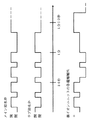
具体的には、図12に示すように、制御部690は、最初に5秒間サブ給水弁50bのみを開き、10秒間メイン給水弁50aのみを開くという動作を4回繰り返し、その後、20秒間サブ給水弁50bのみを開き、その後、所定水位を検知するまでメイン給水弁50aのみを開く。このような動作にすることで、洗剤投入ボックスから水が溢れることもなく、仕上剤も安定して投入することができる。
【0099】
このとき、同図に示すように、制御部690は、イオン溶出ユニット100の電極113・114への電圧印加を、メイン給水弁50aを開いているときのみ行うようにしている。これは、メイン給水弁50aからの給水経路中にイオン溶出ユニット100が配置されているためである。つまり、メイン給水弁50aが閉じているときには、イオン溶出ユニット100中に水がほとんど存在せず、その状態で電圧を印加すると、電流がどのくらい流れるかわからず、金属イオンの溶出量が不明となり、望ましくないからである。
【0100】
また、本実施形態では、イオン溶出ユニット100の制御部690の駆動回路120の電源と、メイン給水弁50aの電磁弁の電源とを、同じ電源から途中で分岐する形で並列にしている。このように各電源を別々に設けることにより、各電源のON/OFFを独立して制御できるので、メイン給水弁50aが開いているとき以外は、より確実に、イオン溶出ユニット100への電圧印加が行われないようにすることができる。
【0101】
また、本実施形態では、同図に示すように、制御部690は、電極113・114の極性が20秒おきに反転するように、上記各電極に電圧を印加している。なお、同図では、一方の電極が陽極になる場合を+で、陰極となる場合を−で表記している。
【0102】
このような電極極性の反転制御を行う理由は、以下の通りである。
▲1▼陽極からは、金属イオンが溶け出すため、一方の電極がずっと陽極になると、その電極だけが減耗してしまう。
▲2▼陰極にはカルシウムなどからなるスケールが付着しやすい。このスケールは、スケールが付着した電極を陽極にすることで除去できるが、一方の電極がずっと陰極になっているとスケールの付着量が多くなり、陽極にしても除去しにくくなる。
これらの不都合を回避するため、本実施形態では、電極の極性を周期的に反転させる制御を行っている。
【0103】
一方、ステップS412’では、金属イオンの添加は行わない。つまり、制御部690がメイン給水弁50aを開き、イオン溶出ユニット100に所定流量の水を流す点は同じであるが、イオン溶出ユニット100中の電極113・114への電圧印加は行わない。それ以外の点では、ステップS412と同じである。
【0104】
(7.アンバランス修正について)
次に、本発明の最も特徴的な部分である、脱水工程時におけるアンバランス修正について説明する。
【0105】
本実施形態の洗濯機601は、図13に示すように、検知手段701と、アンバランス修正手段702とを有している。
【0106】
検知手段701は、ドラム630の回転時のアンバランスを検知するものであり、例えば、タッチセンサ、ショックセンサ、加速度センサなどの物理的な検知手段や、モータの電圧/電流パターンを解析するなどのソフトウェア的な検知手段により構成されている。
【0107】
アンバランス修正手段702は、ドラム630への金属イオン添加水の供給後に実行されるドラム630の脱水回転時に検知手段701がアンバランスを検知した場合に、上記金属イオン添加水の非供給時におけるアンバランス検知時とは異なる処理を実行することにより、上記アンバランスを修正する。このアンバランス修正手段702は、例えば制御部690で構成することが可能であるが、その他のマイクロプロセッサで構成することも可能である。また、上記の異なる処理とは、本実施形態では、上記金属イオン添加水をドラム630に供給して攪拌を行うバランス修正すすぎとしている。
【0108】
脱水工程おいて、検知手段701がアンバランスを検知した場合、アンバランス検知が1回目の場合には、アンバランス修正手段702は、バランス修正として、ドラム630への金属イオン添加水の給水は行わず、タンブリングを行い、洗濯物をほぐし、再度脱水に取り掛かる。そして、一度バランス修正をした後の脱水で、検知手段701が再度アンバランスを検知し、再度バランス修正が必要となった場合には、アンバランス修正手段702は、ドラム630に金属イオン添加水を供給しながらタンブリングを行い、洗濯物をほぐす。
【0109】
ここで、先のすすぎ工程にてドラム630に金属イオン添加水を供給し、洗濯物に対して抗菌処理を行っていた場合には、ドラム630への給水により、洗濯物に付着している一部の金属イオンが失われ、抗菌性が低下する可能性がある。しかし、給水を行わないことによって洗濯物の抗菌性を維持できる効果よりも、給水を行うことによって洗濯物をほぐす効果のほうが大きく、バランス修正効果が大きい。
【0110】
そこで、アンバランス修正手段702は、バランス修正時の給水にも金属イオン添加水を使用し、この金属イオン添加水をドラム630に供給することで、洗濯物の抗菌性の低下を防いでいる。
【0111】
なお、脱水を行うまでに金属イオンの投入が選択されておらず、すすぎ時に抗菌処理を行っていない場合には、アンバランス修正手段702は、バランス修正時に金属イオン添加水の供給は行わず、通常の水道水をドラム630に供給することとなる。
【0112】
以上のように、本実施形態では、アンバランス修正手段702は、抗菌処理後におけるドラム630の脱水回転時のアンバランス修正を行う際に、金属イオン添加水をドラム630に供給して攪拌を行うバランス修正すすぎを行っている。金属イオン添加水の非供給時にアンバランスを検知した場合には、上述のように通常の水道水を供給してアンバランス修正を行うが、抗菌処理を既に行っている場合には、上述したようにバランス修正すすぎという、金属イオン添加水の非供給時とは異なる処理を実行することで、先の抗菌処理にて洗濯物に付与された金属イオンが洗い流されたとしても、後のアンバランス修正での金属イオン添加水の供給により、その洗い流された分を確実に補うことができる。したがって、先の抗菌処理にて洗濯物に付与された抗菌効果を失うことなく、アンバランス修正を行うことができる。つまり、洗濯物に対する抗菌処理の実効性を担保しながら、アンバランス修正を行うことができる。
【0113】
また、先のすすぎ工程にて、既に金属イオンによる抗菌処理が実施されている場合には、アンバランス修正手段702は、バランス修正すすぎにおいて、ドラム630への金属イオン添加水の供給量を、それ以前の工程(すすぎ工程)での金属イオン添加水の供給量よりも少なくするようにしてもよい。このような制御を行っても、脱水時の給水に失われる金属イオンを、バランス修正すすぎでの金属イオン添加水の供給により十分に補足することができるからである。
【0114】
つまり、先の金属イオン添加水の供給工程(すすぎ工程)にて、洗濯物における抗菌効果を発揮させるのに必要な量の金属イオンは既に供給済みであるので、後のバランス修正すすぎにて、洗い流される分を考慮したとしても、抗菌効果を発揮させるのに必要な量の金属イオンを一から供給する必要がない。これにより、バランス修正すすぎにて、洗濯物の抗菌処理に供されずにそのまま洗い流されてしまい、無駄な金属イオンが出現するのを抑えることができる。
【0115】
同様の理由から、先のすすぎ工程にて、既に金属イオンによる抗菌処理が実施されている場合には、アンバランス修正手段702は、バランス修正すすぎにおいて、ドラム630に供給される金属イオン添加水の金属イオン濃度を、それ以前の工程(すすぎ工程)にて供給される金属イオン添加水の金属イオン濃度よりも少なくするようにしてもよい。
【0116】
なお、上述したバランス修正は、縦型の洗濯機にも適用することが可能である。また、金属イオン添加水の供給量の調整は、アンバランス修正手段702が給水弁50の開閉を調整することで可能である。
【0117】
(8.銀イオン濃度の設定)
次に、イオン溶出ユニット100によって生成される金属イオン添加水の銀イオン濃度の設定について説明する。
【0118】
横ドラム式洗濯機601では、縦型の洗濯機よりも洗濯時における水の使用量が少ないため、銀イオン濃度を縦型洗濯機と同等としていたのでは、縦型洗濯機の場合よりも、抗菌処理に供される銀イオン量が少なく、洗濯物への抗菌処理を実効あるものとすることができない。
【0119】
そこで、本実施形態では、横ドラム式洗濯機601での抗菌処理に供される金属イオン添加水(第1金属イオン添加水)の銀イオン濃度と、そのときの洗濯物における抗菌効果との関係を調べ、横ドラム式洗濯機601にて抗菌効果を得るのに必要な銀イオン濃度を調べた。
【0120】
ここで、抗菌効果の評価については、JIS(日本工業規格)L1902:2002に基づく定量試験法(菌液吸収法)により行った。より具体的には、洗濯時に通常すすぎを施した布A1と、抗菌処理(銀イオンコート)を施した布A2とのそれぞれに、菌液(黄色ぶどう球菌)を接種し、37℃の温度で18時間保存後、それぞれの菌数を測定し、これらのlog増減値差を静菌活性値とし、この静菌活性値に基づいて抗菌効果の評価を行った。洗濯は、布負荷7kg、すすぎ時水量30Lで行った。例えば、18時間後の菌数が、布A1で1.9×10⁷個/mlであり、布A2で2.4×106個/mlであれば、静菌活性値は、log(1.9×107)−log(2.4×106)=0.9ということになる。表1は、このときの銀イオン濃度と静菌活性値との関係を示している。
【0121】
【表1】

表1の結果より、銀イオン濃度が単調増加するにつれて、静菌活性値も単調増加することがわかる。また、一般に、静菌活性値が2以上であれば、抗菌効果があると認められている。したがって、表1からは、銀イオン濃度が120ppb以上であれば、静菌活性値も2.5以上であることから、抗菌効果があると言える。
【0123】
ここで、銀イオン濃度と静菌活性値との関係をさらに調べるべく、表1の結果から、銀イオン濃度と静菌活性値との関係のグラフ化を試みた。図14は、表1の結果に基づいて、銀イオン濃度と静菌活性値との関係をグラフ化したものである。
【0124】
図14に示すように、銀イオン濃度を横軸(x軸)に、静菌活性値を縦軸(y軸)にとったとき、表1の銀イオン濃度と静菌活性値とを両座標に持つ3点を滑らかに結ぶ曲線は、単調増加の関数である、y=0.0998exp(0.0268x)で近似できることがわかった。この関数から、静菌活性値が2となる銀イオン濃度、つまり、y=2となるときのxの値を求めると、x=112である。
【0125】
したがって、静菌活性値が2以上であれば、抗菌効果があると認められていることから、図14より、銀イオン濃度が112ppb以上であれば、抗菌効果があると言える。
【0126】
また、検知手段701が脱水時のアンバランスを検知し、アンバランス修正手段702によるバランス修正が行われた場合の試験も実施した。バランス修正時の給水量を12.4L、濃度を48ppbとしたが、静菌活性値は2以上で保たれており、抗菌性は保持されていることが確認できた。
【0127】
また、同じ構成の洗濯機601で、銀イオン濃度120ppb、布負荷7kg、すすぎ時水量30Lとし、ジフテロイドに対する抗菌性能の評価も行った。評価方法としては、JIS(日本工業規格)L1902:2002に基づく定量試験法(菌液吸収法)を参考に、ジフテロイドの一種であるコリネバクテリウムキセロシスに菌種を変更して試験を実施した。その結果、抗菌処理(銀イオンコート)を施した布とJISL1902の菌液吸収法で定められたコントロール布との18時間後の菌数の差の対数値は2.1であった。
【0128】
JISL1902の菌液吸収法では、ジフテロイドとは異なる菌種(黄色ブドウ球菌)ではあるが、菌数の差の対数値が2.0以上で抗菌性があるとしている。また、JISZ2801や全国家庭電気製品公正取引協議会の「菌等の抑制に関する用語使用基準」などの抗菌性能や除菌性能を測る試験においても、菌数の差の対数値が2.0以上であるということが、抗菌力・除菌力を評価する1つの目安とされている。したがって、上記の試験結果より、上記条件のもとでは、ジフテロイドに対する抗菌力もあると言える。
【0129】
一方、銀イオン濃度が900ppbを超える水(金属イオン添加水)で洗濯物のすすぎを繰り返したところ、すすぎ回数3回のときは洗濯物に外見上の変化は認められなかったが、すすぎ回数が5回になると、天日乾燥の後の反射率がすすぎ前に比べて、3%低下した。これは、銀化合物に由来する黒い変色物が洗濯物に付着しているためと考えられる。白色の洗濯物では、そのような黒化物の付着は目立ちやすく、また、白色でない洗濯物であっても、洗濯を繰り返していくと、黒化物が目立ってくる可能性もある。このことから、銀イオン濃度の上限は、900ppbであると考えることができる。
【0130】
以上より、横ドラム式洗濯機601において、イオン溶出ユニット100から溶出される金属イオン(銀イオン)が添加された金属イオン添加水における銀イオン濃度は、112ppb以上900ppb以下であることが好ましく、120ppb以上900ppb以下であれば、さらに好ましいと言える。
【0131】
以上のように、本実施形態の横ドラム式洗濯機601は、電極113・114から金属イオンを溶出させて水に添加するイオン溶出ユニット100と、回転軸が鉛直方向に対して交差するように配置され、洗濯物が収容されるドラム630とを備えた洗濯機であって、上記金属イオンは、銀イオンであり、金属イオン添加水(第1金属イオン添加水)における銀イオン濃度が、112ppb以上である構成である。
【0132】
これにより、例えば縦型の洗濯機での洗濯物の抗菌処理に供される第2金属イオン添加水(銀イオン濃度;3〜50ppb)と比べて、同一水量に含まれる銀イオン量が多いので、元々、水の使用量の少ない横ドラム式洗濯機601でも、洗濯物に対する抗菌効果を発揮するのに必要な銀イオン量(静菌活性値が2以上となる銀イオン量)を最低限確保することができる。したがって、横ドラム式洗濯機601においても、縦型洗濯機での抗菌処理にて得られる抗菌効果と同等もしくはそれ以上の抗菌効果を得ることができ、洗濯物に対する抗菌処理を確実に行って、抗菌効果を確実に発揮させることができる。
【0133】
特に、第1金属イオン添加水における銀イオン濃度が、120ppb以上であれば、銀イオン濃度112ppbのときよりも、さらに多くの量の銀イオンを水に含ませることができる。したがって、第1金属イオン添加水の量が、銀イオン濃度112ppbのときと同じ量であった場合には、そのような銀イオン濃度(112ppb)の第1金属イオン添加水を用いる場合に比べて、銀イオンによる抗菌効果をさらに発揮させることができる。また、第1金属イオン添加水の量が、銀イオン濃度が112ppbのときよりも少ない場合でも、それと同等の銀イオン量を確保することができるので、抗菌効果を得ながらにして、さらに水の量を減らすことができ、節水効果が得られるという利点もある。
【0134】
また、本実施形態の横ドラム式洗濯機601では、第1金属イオン添加水における銀イオン濃度が、900ppb以下である構成である。これにより、銀イオン量の過多により、銀化合物(黒化物)が発生して洗濯物へ付着し、洗濯物が汚れるのを抑制することができる。
【0135】
以上のように金属イオンの濃度制御を行うことによって、水量変化があっても、抗菌処理に必要な金属イオン量を確保することができることから、本実施形態の横ドラム式洗濯機601は、以下のように表現することもできる。
【0136】
すなわち、本実施形態の横ドラム式洗濯機601は、洗濯物が収容される収容槽(ドラム630)と、電極113・114から金属イオンを溶出させて水に添加し、金属イオン添加水を上記収容槽に供給するイオン溶出ユニット100とを備えた洗濯機であって、イオン溶出ユニット100からドラム630に供給される金属イオン添加水の水量に応じて、上記金属イオン添加水の金属イオン濃度を変化させる制御部690(制御手段)を備えている構成である。
【0137】
例えば、洗濯物の量が一定の場合、ドラム630に供給する金属イオン添加水の水量を少なくすると、制御部690が上記金属イオン添加水の金属イオン濃度を例えば112ppb以上に増大させる。このような濃度制御により、金属イオン添加水の供給量が少ない場合でも、上記洗濯物に対する抗菌効果を発揮するのに必要な金属イオン量を確保することができ、洗濯物に対する抗菌処理を確実に行って、抗菌効果を確実に発揮させることができる。
【0138】
また、逆に、ドラム630に供給する金属イオン添加水の水量を多くすると、制御部690が上記金属イオン添加水の金属イオン濃度を例えば112ppb以上となる範囲で減少させる。金属イオン濃度が一定の場合、金属イオン添加水の水量が増大すると、これに伴って、それに含まれる金属イオン量も増大するが、増大しすぎると、余分な金属イオンは洗濯物の抗菌処理に供されず、排水としてそのまま流されて無駄となる。また、洗濯物に付着する金属も増大し、洗濯物が汚れる事態も生ずる。したがって、上記の濃度制御により、このような不都合を回避することができる。
【0139】
なお、制御部690は、イオン溶出ユニット100からドラム630に供給される金属イオン添加水の供給水位に応じて、上記金属イオン添加水の金属イオン濃度を変化させる構成であってもよく、この場合でも、上記と同様の効果を得ることができる。
【0140】
また、イオン溶出ユニット100からドラム630に供給される金属イオン添加水の水量が変化すると、浴比も変化する。ここで、浴比とは、洗濯物の量(kg)と、上記ドラム630に供給される水の水量(L)との比(L/kg)を示すもの、言い換えれば、洗濯物1kgあたりの使用水量を示すものである。したがって、制御部690は、浴比に応じて、上記金属イオン添加水の金属イオン濃度を変化させる構成であってもよいと言える。例えば、制御部690は、浴比が小さくなれば、上記金属イオン濃度を例えば112ppb以上に増大させる一方、浴比が大きくなれば、上記金属イオン濃度を例えば静菌活性値が2以上となる範囲で減少させる制御を行うことが考えられる。
【0141】
なお、ドラム630に投入された洗濯物の量(総重量、負荷量)は、図示しない検知手段により検知することが可能である。したがって、制御部690は、上記検知手段にて検知された洗濯物の量と、操作パネル616にて設定される使用水量とに基づいて浴比を演算し、この浴比に応じて金属イオン濃度を変化させることになる。
【0142】
この構成であっても、浴比の変化にかかわらず、洗濯物の量に応じて必要な金属イオン量を常に確保することができる。その結果、収容槽に供給する金属イオン添加水の水量変化があり、浴比が変化した場合でも、所定量の洗濯物に対する抗菌処理を確実に行って、抗菌効果を確実に発揮させることができる。併せて、必要以上の金属イオンが洗濯物の抗菌処理に供されず、排水としてそのまま流されて無駄となったり、洗濯物に付着する金属の増大によって洗濯物が汚れたりするのも回避することができる。
【0143】
また、布負荷7kg、すすぎ時水量30Lの条件、すなわち、洗濯物の布負荷7kgで浴比4.3L/kgの条件で種々実験を行った結果を示したが、この結果から、洗濯物の布負荷7kgで浴比4.3L/kg以下で洗濯やすすぎなどを行う洗濯機では、金属イオン濃度を112ppb以上(より好ましくは、120ppb以上)とすることで、金属イオンを添加した洗濯物における静菌活性値を2以上とすることができ、良好な抗菌効果を洗濯物に与えることができると言える。したがって、浴比5L/kg(洗濯物の布負荷7kg)以下で洗濯を行う洗濯機では、洗濯物の静菌活性値は2以上もしくはそれに近い値が得られると考えられ、良好な抗菌効果が得られると考えられる。
【0144】
つまり、洗濯物に使用する金属イオン添加水の浴比が5L/kg(洗濯物の布負荷7kg)以下の場合には、制御部690がイオン溶出ユニット100から供給される金属イオン添加水の金属イオン濃度を112ppb以上(望ましくは、浴比4.3L/kg(洗濯物の布負荷7kg)以下であれば金属イオン濃度120ppb以上)となるように制御することで、洗濯物に抗菌効果を確実に与えることができると考えられる。これにより、不必要な量の金属イオンを消費することなく、十分な静菌活性値が得られる金属イオンを洗濯物に添加することができる。
【0145】
言い換えれば、低浴比で動作する洗濯機における必要最低量の金属イオン濃度を設定したことで、本来吸水性の高いものや低いものが混在する洗濯物に対して、低い金属イオン濃度であれば十分な抗菌効果を与えることができず、また、過剰なまでに高い金属イオン濃度では、不必要な金属イオンを消費することになるという、洗濯機特有の問題点を解決することができ、効率的な金属イオンによる抗菌効果を洗濯物に与えることができる。
【0146】
なお、以上では、金属イオン濃度の制御を制御部690によって行っているが、金属イオン濃度を112ppb以上(好ましくは120ppb以上)900ppb以下となる範囲内で、金属イオン濃度を予め設定しておく構成としても、勿論構わない。
【0147】
また、有効な静菌活性値(例えば2以上)を得るのに適した、一定量の洗濯物(例えば7kg)に使用する一定濃度かつ一定水量の金属イオン添加水(例えば90ppbで42L)を、金属イオンを添加する場合の基準浴比(6L/kg)とし、上記金属イオン濃度(90ppb)を、基準浴比において抗菌効果が発揮されていると評価できる静菌活性値が得られる場合の濃度(基準濃度)とすれば、本発明では、以下の制御を行ってもよい。
【0148】
すなわち、制御部690は、金属イオン濃度が予め定めた基準濃度となるように、イオン溶出ユニット100による金属イオンの溶出量を制御する際、洗濯・すすぎ・脱水・乾燥のいずれか一つ以上の工程において使用する使用水量の浴比が、これと同一の量(総重量、負荷量)の洗濯物における基準浴比に対して小さくなった場合には、上記金属イオン濃度を基準濃度よりも高くし、上記工程における浴比が、これと同一量の洗濯物における基準浴比に対して大きくなった場合には、上記金属イオン濃度を上記一定の基準濃度で維持する、または上記基準濃度よりも低くする制御を行っても良い。
【0149】
このような金属イオン濃度制御により、どのように浴比が変化しても、用いる洗濯物の量に応じて決まる、抗菌効果を発揮するのに必要な金属イオン量(例えば静菌活性値2以上となる金属イオン量)をほとんど過不足なく確保することができる。したがって、浴比が変化しても、使用する金属イオンの無駄を省きながら、用いる洗濯物に対して抗菌効果を確実に付与することができ、浴比の変化にも十分対応することができる。
【0150】
以上のことから、本実施形態の洗濯機1は、給水水量、給水水位、浴比がどのように変化しても、金属イオンを添加した洗濯物の静菌活性値が2以上となるように、制御部690がイオン溶出ユニット100から供給される金属イオン添加水の金属イオン濃度を変化させる制御を行えばよいと言える。
【0151】
また、以上のことから、横ドラム式洗濯機601は、電極113・114から金属イオンを溶出させて水に添加するイオン溶出ユニット100と、回転軸が鉛直方向に対して交差するように配置され、洗濯物が収容されるドラム630とを備えた洗濯機であって、上記金属イオンは、銀イオンであり、上記ドラム630内の洗濯物の抗菌処理に供される第1金属イオン添加水に含まれる銀イオン量が、回転軸が鉛直方向となるように洗濯槽が配置される縦型洗濯機での洗濯物の抗菌処理に必要な量の第2金属イオン添加水に含まれる銀イオン量以上となるように、上記第1金属イオン添加水における銀イオン濃度が設定されている構成であるとも言うことができる。
【0152】
また、横ドラム式洗濯機601は、電極113・114から金属イオンを溶出させて水に添加するイオン溶出ユニット100と、回転軸が鉛直方向に対して交差するように配置され、洗濯物が収容されるドラム630とを備えた洗濯機であって、上記金属イオンは、銀イオンであり、上記ドラム630内の洗濯物の抗菌処理に供される第1金属イオン添加水の銀イオン濃度が、回転軸が鉛直方向となるように洗濯槽が配置される縦型洗濯機での洗濯物の抗菌処理に必要な第2金属イオン添加水の量よりも少ない水量で、上記第2金属イオン添加水による抗菌効果と同等の抗菌効果を得ることができる濃度に設定されている構成であるとも言うことができる。
【0153】
なお、本実施形態では、金属イオンとして、主に銀イオンを使用する例について説明したが、水量や浴比に応じて金属イオン添加水の金属イオン濃度を変化させる本発明の構成は、金属イオンとして、銅イオンや亜鉛イオンを使用する場合にも、勿論、適用することができる。また、その場合であっても、金属イオンの濃度変化の適正な範囲は、およそ、112ppb以上900ppb以下、好ましくは120ppb以上900ppb以下と考えられる。
【0154】
(9.金属イオン添加水の水量制御)
次に、イオン溶出ユニット100から供給される金属イオン添加水の水量制御について説明する。
【0155】
横ドラム式洗濯機601における洗濯工程は、洗い工程、すすぎ工程、脱水工程、必要に応じて乾燥工程の複数の個別工程からなっているのは、上述した通りである。本実施形態では、制御手段としての制御部690が、イオン溶出ユニット100からの金属イオン(銀イオン)の溶出を上記いずれかの個別工程の中で行うとともに、上記金属イオンの溶出を行う個別工程の水量を、他の工程の水量よりも増大させる制御を行っている。
【0156】
本実施形態では、上述したように、上記金属イオンの溶出を、上記個別工程としてのすすぎ工程の中で行っているが、このとき、制御部690は、上記すすぎ工程の水量を、その前に行われる洗い工程の水量よりも増大させる制御を行っている。例えば、洗い工程における水量が20Lであれば、すすぎ工程における水量は例えば30Lである。
【0157】
なお、このような水量制御は、制御部690が上記個別工程ごとに給水弁50の開閉を調節することで行うことが可能である。具体的には、制御部690は、水位センサ(図示せず)が所定水位を検出するまで、給水弁50を開放しつづけ、所定水位を検出すると給水弁50を閉じることにより、水量を調節する。また、ここでは、金属イオン溶出工程にて溶出された金属イオン(銀イオン)が添加された水(金属イオン添加水)の銀イオン濃度は、抗菌処理に好適な範囲である、上述した112ppb以上900ppb以下であるとする。
【0158】
このように、制御部690が、銀イオンの溶出を行う個別工程(例えばすすぎ工程)における水量を、他の個別工程(例えば洗い工程)における水量よりも多くする制御を行うことにより、ドラム630の中の洗濯物(例えば布)がその個別工程(すすぎ工程)にて水により浸りやすくなる。この結果、溶出された銀イオンが、より均一に洗濯物に付着しやすくなる。したがって、洗濯物における抗菌効果を洗濯物全体にわたってより均一に得ることができ、抗菌処理をより実効あるものとすることができる。
【0159】
特に、制御部690が、銀イオンの溶出をすすぎ工程の中で行い、すすぎ工程における水量を、その前の洗い工程における水量よりも増大させる制御を行うことで、洗い工程にて汚れの除去された洗濯物のすすぎ時に、洗濯物が均一にすすぎ水(金属イオン添加水)に浸り、すすぎ水に含まれる銀イオンが洗濯物全体により均一に付着する。したがって、すすぎ時における抗菌処理により、洗濯物全体にわたって均一な抗菌効果を確実に得ることができる。
【0160】
(10.ドラム回転制御)
次に、すすぎ工程におけるドラム630の回転制御について説明する。
【0161】
本実施形態では、図11のフローチャートで示したように、イオン溶出ユニット100からの金属イオン(銀イオン)の溶出は、図6のすすぎ工程のフロー中、例えばステップS401の給水の段階、すなわち、ステップS500の中間脱水工程後に遂行されている。このとき、制御部690は、上記中間脱水後に、金属イオン添加水をドラム630に給水し、ドラム630を回転させることにより、ドラム630内面に貼り付いた洗濯物を上記金属イオン添加水に浸漬させる制御を行っている。
【0162】
縦型の洗濯機の場合、脱水時の洗濯槽の高速回転により、脱水後の洗濯物(例えば布)が洗濯槽内面の全面に強く貼り付いてしまうため、その後、洗濯物の全てに対して銀イオン処理を施す場合には、洗濯槽内の銀イオン水の水位を上げて、全ての洗濯物を銀イオン水に浸し、洗濯物を洗濯槽内面からはがすべく、洗濯物を強く攪拌する必要がある。
【0163】
このため、縦型の洗濯機では、すすぎ工程での中間脱水後に銀イオン給水を行い、例えば10分間の銀イオンすすぎを行う場合、例えば最初の4分間は、パルセータを1.9秒間ONする一方、0.7秒間OFFし、洗濯物を強く攪拌することになる。なお、パルセータによる攪拌は、布(洗濯物)を傷める作用が強く、また、モータへの負荷も大きいことから、10分間行うことはできないため、最初の4分間だけ攪拌を行うのが通常である。
【0164】
これに対して、本実施形態の横ドラム式洗濯機601では、ドラム630が横軸回転もしくはそれに近い回転であるため、ドラム630の回転による中間脱水によって、ドラム630の内面に洗濯物が貼り付いても、ドラム630を回転させるだけで、当該洗濯物を、ドラム630内に給水された金属イオン添加水に浸漬させることができる。なお、ドラム630が回転し続けると、ドラム630内面に貼り付いた洗濯物は、金属イオン添加水への浸漬と当該水からの離脱とを繰り返す。
【0165】
また、中間脱水後の洗濯物は、ドラム630の内面に貼り付いており、かさばらないため、銀イオン水(金属イオン添加水)のドラム630内での水位が低くても、当該銀イオン水に浸りやすくなる。よって、金属イオン添加水を使わない通常のすすぎ時の浴比に対して、中間脱水後の金属イオン添加水によるすすぎの浴比を小さくして、銀イオン濃度を上げる制御をして、節水してもよい。
【0166】
したがって、横ドラム式洗濯機601では、中間脱水後の抗菌処理において、縦型洗濯機の洗濯槽ほど、ドラム630を高速回転させる必要がない。この結果、ドラム630内の洗濯物を強く攪拌させなくても済み、例えば10分間、比較的緩やかな回転速度(例えば50回転/min)でドラム630を回転させることができる。その結果、洗濯物の攪拌に伴う損傷(例えば布傷み)を抑制することができる。また、ドラム630の低速回転により、その駆動手段(例えばモータ)の負荷を軽減することもでき、駆動手段ひいては横ドラム式洗濯機601における消費電力を低減することもできる。
【0167】
特に、制御部690は、10回転/min以上120回転/min以下の比較的低速な回転速度でドラム630を回転させることによって、ドラム630内面に貼り付いた洗濯物を上記金属イオン添加水に浸漬させることにより、上記の効果を確実に得ることができる。
【0168】
以上のような作用効果を奏することから、本実施形態の洗濯機601は、洗濯物を収容する収容槽が、回転軸が鉛直方向に対して交差するように設けられるドラム630であり、上記洗濯物の洗濯工程は、すすぎ工程を含んでおり、制御部690(制御手段)、イオン溶出ユニット100での金属イオンの溶出を上記すすぎ工程の中で行うとともに、上記すすぎ工程における中間脱水後に、金属イオン添加水をドラム630に給水し、ドラム630を回転させることにより、ドラム630内面に貼り付いた洗濯物を当該金属イオン添加水に浸漬させる構成であると言うことができる。
【0169】
(11.機内の抗菌・抗カビ効果)
次に、横ドラム式洗濯機601の機内の抗菌・抗カビ効果について説明する。
【0170】
横ドラム式の洗濯機601では、ドラム630や水槽620がほぼ横向きに配置されるため、洗濯物を洗濯機601の正面から入れることが多い。そのため、ドラム630へ洗濯物を収容するためのフタであるドア612は、通常、図1に示したように洗濯機601の正面に設けられる。
【0171】
しかし、このように洗濯機601の上面以外の面にドア612を設けると、そこから水が漏れる可能性がある。そのため、洗濯機601では、ドアパッキン613を設けており、ドア612を閉めたときに、ドア612と本体610とのシール性が高く、本体610内部を密閉できる構造となっている。また、横ドラム式の洗濯機601では、縦型の洗濯機と違って、不使用時にドア612を開けておくことも、スペースの関係上難しい。
【0172】
したがって、横ドラム式の洗濯機601では、洗濯終了後に洗濯機601内部に残った水が、乾燥しにくい状況にある。また、横ドラム式の洗濯機601の中には、システムキッチンへの組み込みの需要により、ポンプによる排水を行うものもあるが、特にこの場合、重力による自然排水に比べ、残水自体が多くなる。
【0173】
また、最近は、縦型の洗濯機においても、乾燥機能を備え、乾燥時の熱や湿気あるいは発生する埃を外部に漏らさないため、密閉性が高い構造になっているものがある。このような機種では、横ドラム式の洗濯機601と同様に、機内に残水が生じやすい。
【0174】
このように機内に残水が存在すると、この残水が腐敗して臭気を発したり、カビも繁殖しやすくなり、衛生面が低下する。特に、機内は、洗濯物に付着していた汚れや洗剤カスなどの栄養分が豊富で、菌、カビなどが増殖しやすい。また、そのような菌が洗濯物に付着すると、洗濯物が汚れたり、洗濯済みの衣類を身に付けたときに、皮膚に悪影響を与える可能性もある。
【0175】
そこで、本実施形態では、以下の構成を採用することにより、このような不都合を回避するようにしている。
【0176】
本実施形態の横ドラム式洗濯機601では、洗濯工程における全個別工程(洗い工程、すすぎ工程、脱水工程、必要に応じて乾燥工程)が終了した後に機内に残存する水(より詳しくは、イオン溶出ユニット100から排水管664を介しての排水経路内に残存する水)が、イオン溶出ユニット100から溶出される金属イオン(銀イオン)を含む金属イオン添加水(銀イオン水)となっている。これは、制御部690が、洗濯工程のうち、水を必要とする最終の個別工程において、イオン溶出ユニット100から金属イオンを溶出し、上記水に添加する制御を行うことで、実現可能である。
【0177】
例えば、洗濯モードによって乾燥工程が実行されない場合は、図4のフローチャートで示したように、制御部690は、水の供給を必要とする個別工程の最終工程(すすぎ工程の最終すすぎ工程(図4のステップS400−3))において、上述した銀イオン給水を行う。この場合、ドラム630内に給水された銀イオン水は、洗濯物の抗菌処理に供された後、脱水工程によって脱水され、機外に排水される。このとき、上記銀イオン水は、完全に機外に排出されるわけではなく、排出しきれずに、僅かながら、ドラム630内や排水経路(例えば排水管664)中に残るのが通常である。また、水の供給を必要とする最終の個別工程終了後は、その後にドラム630内や排水経路を別の水が流れることもない。
【0178】
また、上記最終の工程が水冷除湿による乾燥工程である場合には、制御部690は、当該乾燥工程において、イオン溶出ユニット100から溶出される金属イオンを、ドラム630から排出される空気を冷却するための冷却水に添加する制御を行う。この場合、当該空気の冷却が終わった後は、当該冷却水は、排水経路(例えば排水管664)を介して機外に排出される。この場合であっても、上記冷却水は、完全に機外に排出されるわけではなく、排出しきれずに、僅かながら、上記排水経路中に残るのが通常である。また、乾燥工程は、洗濯工程の最終工程であるので、その後に上記排水経路を別の水が流れることもない。
【0179】
なお、水冷除湿方式を採用する乾燥工程では上記冷却水が必要であり、乾燥工程は洗濯工程の最終で行われる個別工程であることから、当該乾燥工程は、洗濯工程の中でも、水の供給を必要とする最終個別工程であると言える。
【0180】
以上のように、制御部690(制御手段)は、洗濯物の洗濯工程を構成する少なくとも1個の個別工程が実行されるときに、その個別工程のうち、水を必要とする最終の個別工程にて、イオン溶出ユニット100から金属イオンを溶出させて水に添加させる制御を行う。これにより、洗濯工程の全個別工程が終了した後は、機内(イオン溶出ユニット100から排水管664を介しての排水経路中)に水が残存するとしても、その残存する水が、金属イオン添加水となる。
【0181】
ここで、機内に残存する水が、通常の水道水であれば、その水が腐敗して臭気を発したり、カビが繁殖することもある。特に、横ドラム式洗濯機601では、前面のドア612などから水が漏れるのを防ぐ必要があるため、縦型の洗濯機に比べて密閉性が高く、それゆえ、特に、機内のドラム630内に残存する水が蒸発しにくく、臭気やカビが発生しやすいことは、上述した通りである。
【0182】
しかし、本実施形態の上述した構成を採用することにより、最終工程終了後に機内に残存する水が、抗菌性を有する金属イオン水であるので、密閉性の高い機内でも、上記金属イオン水に含まれる金属イオン(銀イオン)による抗菌作用により、残水から臭気が発生したり、残水が原因で機内でカビが繁殖するのを確実に抑えることができる。その結果、衛生面に優れた横ドラム式洗濯機601を実現することができる。
【0183】
また、水を必要とする上記最終の個別工程が、収容槽に収容される洗濯物をすすぐ、すすぎ工程であるときは、制御部690は、上記すすぎ工程において、イオン溶出ユニット100から溶出される金属イオンを、上記収容槽に供給される水に添加させる構成である。これにより、すすぎ工程終了後に機内に残存する金属イオン添加水により、臭気やカビの発生を抑えて、衛生面を確実に向上させることができる。
【0184】
また、上記最終の個別工程が、洗濯物を収容する収容槽に温風を供給して洗濯物を乾燥させるとともに、上記収容槽から排出される空気を冷却水により冷却する乾燥工程である場合には、制御部690は、上記乾燥工程において、イオン溶出ユニット100から溶出される金属イオンを、上記冷却水に添加させる構成である。これにより、乾燥工程終了後に機内に残存する金属イオン添加水により、臭気やカビの発生を抑えて、衛生面を確実に向上させることができる。
【0185】
ところで、以上では、収容槽(ドラム630)から水が排出される排出経路(以下、第1の排出経路とも称する)と、乾燥工程にて使用される冷却水の排出経路(以下、第2の排出経路とも称する)とが共通していることを前提に話を進めたが、洗濯機601の構造上、必ずしもそのように排出経路を共通にすることが困難な場合もある。つまり、第1の排出経路と第2の排出経路とが、その一部または全部が異なって設けられる場合もある。
【0186】
このように第1の排出経路と第2の排出経路の少なくとも一部が異なる場合、洗濯物の洗濯工程を構成する個別工程として、(1)上記収容槽に温風を供給して洗濯物を乾燥させるとともに、上記収容槽から排出される空気を冷却水により冷却する乾燥工程と、(2)上記乾燥工程の直前で上記収容槽に水を供給する工程(例えばすすぎ工程)とが、選択された洗濯モードに応じて両方とも実行されると、水を必要とする最終の個別工程は、上記(1)の工程となるため、上記最終の個別工程で使用する冷却水にのみ金属イオンを添加させても、第2の排出経路中に金属イオン添加水を残すことはできるが、第1の排出経路中に金属イオン添加水を残すことができない。
【0187】
そこで、第1の排出経路と第2の排出経路の少なくとも一部が異なり、上記(1)(2)の工程が両方とも実行される場合は、制御部690は、イオン溶出ユニット100から溶出される金属イオンを、上記(2)の工程にて上記収容槽に供給される水と、上記(1)の乾燥工程にて使用される上記冷却水との両方に添加させる制御を行うようにすればよい。
【0188】
これにより、上記(1)(2)の各工程の終了後は、第1および第2のそれぞれの排出経路において、最終的に金属イオン添加水を残すことができる。したがって、機内のそれぞれの排出経路内の残水の腐敗による臭気の発生やカビの繁殖を抑えることができ、衛生面に優れた洗濯機を実現することができる。
【0189】
(12.その他)
以上、本発明の実施形態につき説明したが、本発明の範囲はこれに限定されるものではなく、発明の主旨を逸脱しない範囲で種々の変更を加えて実施することができる。
【0190】
例えば、イオン溶出ユニット100の配置個所は給水弁50から給水口53までの間に限られる訳ではない。接続管51から給水口53までの間であればどこでもよい。すなわち給水弁50の上流側に置くこともできる。イオン溶出ユニット100を給水弁50より上流に置くこととすれば、イオン溶出ユニット100は常に水に漬かっていることになり、シール部材が乾燥して変質し、水もれを生じるといったことがなくなる。
【0191】
また、イオン溶出ユニット100を外箱10の外に置いてもよい。例えばイオン溶出ユニット100を交換可能なカートリッジの形状にし、接続管51にネジ込みなどの手段で取り付け、このカートリッジに給水ホースを接続するといった構成が考えられる。
【0192】
カートリッジ形状にするかどうかは別として、イオン溶出ユニット100を外箱10の外に置くこととすれば、洗濯機1の一部に設けた扉を開けたり、パネルを外したりすることなくイオン溶出ユニット100を交換でき、メンテナンスが楽である。しかも洗濯機1の内部の充電部に触れることがないので安全である。
【0193】
上記のように外箱10の外に置いたイオン溶出ユニット100には、駆動回路120から延ばしたケーブルを、防水コネクタを介して接続し、電流を供給すればよいが、駆動回路120からの給電に頼らず、電池を電源として駆動することとしてもよいし、給水の水流に接するように水車を備えた水力発電装置を電源として駆動することとしてもよい。
【0194】
イオン溶出ユニット100を独立した商品として販売し、洗濯機以外の機器への搭載を促進してもよい。
【0195】
また、イオン溶出ユニット100を、水槽620内で、所定水位まで給水された時に水に浸る位置に配置してもよい。そうすれば、イオン溶出ユニット100が水槽620内の水に浸っているときは、給水のタイミングと無関係にいつでも金属イオンを溶出させることができる。したがって、金属イオンを溶出させるのに十分な時間をかけることができ、金属イオンを高濃度で使用したり、あるいは、所定濃度を得るのに低い電流・電圧で済ませたりすることができる。
【0196】
また、イオン溶出のために洗濯工程に給水シーケンスを設ける必要がないので、洗濯の全工程に要する時間を長くしなくて済む。さらに、ドラム630に給水する水の中に金属イオンを添加する場合、金属イオンの溶出に必要な時間を確保するため、給水流量を絞る必要も出てくる。これは洗濯時間の長時間化に結びつくが、この構成であればそのような配慮は不要である。
【0197】
また、本実施形態では、回転軸が鉛直方向に対して交差するように配置されるドラム630を、洗濯物が収容される収容槽として有する横型の洗濯機601について説明したが、水量や浴比に応じて金属イオン添加水の金属イオン濃度を変化させる構成をはじめとする本実施形態で述べた構成は、回転軸が鉛直方向となるように洗濯槽を上記収容槽として有する縦型の洗濯機にも、勿論、適用することができる。
【0198】
また、金属イオンを溶出するイオン溶出手段に関しては、上述する構成(イオン溶出ユニット100)に限定されるわけではない。イオン溶出手段は、例えば、カートリッジ内に金属イオン溶出材(銀溶出材であれば硫化銀など)を装填し、カートリッジ内に水を通すことで金属イオン溶出するもので構成されても構わない。給水される限られた量の水の金属イオン濃度を短時間で細かく制御できる点では、上述したイオン溶出ユニット100か、これと同等の金属イオン濃度の制御ができるものが好適である。
【0199】
【発明の効果】
以上のように、本発明の洗濯機では、イオン溶出手段から収容槽に供給される金属イオン添加水の供給後に実行される上記収容槽の脱水回転時に、検知手段が上記収容槽のアンバランスを検知した場合に、アンバランス修正手段が、上記金属イオン添加水の非供給時におけるアンバランス検知時とは異なる処理(例えば、イオン溶出手段にて得られる金属イオン添加水を収容槽に供給して攪拌を行うバランス修正すすぎ)を行う構成である。
【0200】
これにより、先の金属イオン添加水の供給による抗菌処理にて洗濯物に付与された金属イオンが洗い流されたとしても、後の金属イオン添加水の供給により、その洗い流された分を確実に補うことができる。したがって、先の抗菌処理にて洗濯物に付与された抗菌効果を失うことなく、アンバランス修正を行うことができる。つまり、洗濯物に対する抗菌処理の実効性を担保しながら、アンバランス修正を行うことができる。
【図面の簡単な説明】
【図1】本発明の実施の一形態に係る横ドラム式の洗濯機の外観構成を示す斜視図である。
【図2】上記洗濯機の概略の構成を示す垂直断面図である。
【図3】上記洗濯機が備える給水口の構成を模式的に示す説明図である。
【図4】上記洗濯機における洗濯工程全体の流れを示すフローチャートである。
【図5】上記洗濯工程における洗い工程の詳細を示すフローチャートである。
【図6】上記洗濯工程におけるすすぎ工程の詳細を示すフローチャートである。
【図7】上記洗濯工程における脱水工程の詳細を示すフローチャートである。
【図8】上記洗濯機が備えるイオン溶出ユニットの概略の構成を示す水平断面図である。
【図9】上記イオン溶出ユニットの概略の構成を示す垂直断面図である。
【図10】上記イオン溶出ユニットを駆動するための駆動回路の概略の構成を示す説明図である。
【図11】上記イオン溶出ユニットからの金属イオンの溶出および金属イオン添加水の投入のシーケンスを示すフローチャートである。
【図12】上記洗濯機のメイン給水弁およびサブ給水弁の開閉タイミングと、イオン溶出ユニットの各電極への電圧印加タイミングとを示すタイミングチャートである。
【図13】上記洗濯機において、脱水時のドラムのアンバランスを修正するための構成を示すブロック図である。
【図14】金属イオン添加水における銀イオン濃度と静菌活性値との関係を示すグラフである。
【符号の説明】
100 イオン溶出ユニット
120 駆動回路(制御手段)
601 洗濯機
630 ドラム(収容槽)
690 制御部(制御手段)
701 検知手段
702 アンバランス修正手段[0001]
TECHNICAL FIELD OF THE INVENTION
The present invention relates to a washing machine that supplies metal ion-added water to a storage tub (drum or washing tub) from an ion eluting unit and performs an antibacterial treatment on laundry stored in the storage tub. The present invention relates to a washing machine that corrects imbalance of a storage tub during spinning.
[0002]
[Prior art]
When washing laundry in a washing machine, it is common to add a finishing substance to water (particularly, rinsing water). Common finishing materials are softeners and glues. In addition to this, recently, there is a growing need for a finishing treatment for imparting antibacterial properties to laundry.
[0003]
It is desirable that the laundry be sun-dried from a sanitary viewpoint. However, in recent years, the number of families who have no one at home during the daytime has increased due to the increase in the female employment rate and the progress of nuclear families. In such a home, you have to rely on indoor drying. In addition, even in a home where somebody is at home during the day, when it rains, indoors are dried.
[0004]
In the case of indoor drying, bacteria and mold are more likely to grow on the laundry than in the case of sun drying. This tendency is remarkable when it takes a long time to dry the laundry, for example, during high humidity or low temperature such as during the rainy season. Also, depending on the breeding situation, the laundry may give off a bad smell.
[0005]
In recent years, there has been an increasing awareness of savings, and many households reuse bath water after washing for washing. However, there is also a problem that the bath water left overnight has an increased number of bacteria, and the bacteria adhere to the laundry and further propagate, causing an unpleasant odor.
[0006]
For this reason, in households that are forced to dry indoors on a daily basis or in households that reuse bath water for washing, there is a strong demand for antibacterial treatment of cloth to suppress the growth of bacteria and mold.
[0007]
On the other hand, in recent years, there has been an increasing number of garments in which fibers have been subjected to antibacterial and deodorant processing and antibacterial processing. However, it is difficult to prepare all household textile products with antibacterial and deodorant finishes. In addition, the effect of the antibacterial and deodorant treatment decreases as washing is repeated.
[0008]
Therefore, the idea of antibacterial treatment of laundry was born each time washing was performed. For example,
[0009]
[Patent Document 1]
Published Japanese Utility Model Application No. 5-74487 (published October 12, 1993)
[Patent Document 2]
JP 2001-276484 A (released October 9, 2001)
[0010]
[Problems to be solved by the invention]
By the way, the above-mentioned washing machines of
[0011]
Here, in a vertical washing machine, since the rotation axis of the washing tub is along the vertical direction, the gravity acting on the laundry is in a direction parallel to the rotation axis. In this case, the bias in the washing tub hardly occurs, and the center of gravity of the laundry tends to be on the rotation axis. Therefore, imbalance is unlikely to occur. In addition, unbalance is a phenomenon in which the laundry is placed unevenly in the washing tub, so that the rotation balance is not well balanced at the start of dehydration, and the washing tub and the main body of the washing machine vibrate greatly in the subsequent dehydration process. To tell. In a vertical washing machine, the center of gravity of the washing tub is located on a vertical rotation axis, and the rotation axis is directly above the motor. Therefore, the load of the washing tub can be supported by the motor unit.
[0012]
On the other hand, in the horizontal type washing machine, since the rotation axis is not in the vertical direction, the gravity acting on the laundry is different from the direction of the rotation axis. That is, when the drum is stationary, the laundry collects at the lower portion of the drum, but in that state, the center of gravity of the laundry is not on the rotation axis. If the drum rotates and centrifugal force acts on the laundry, the laundry will be pressed toward the periphery of the drum, but if it is not uniform, it will be unbalanced. Therefore, in a horizontal type washing machine in which the rotation axis is not vertical, due to its structure, the frequency of occurrence of imbalance is extremely high.
[0013]
Therefore, it is necessary to correct such imbalance. As a method of correcting the imbalance, it is common to put water in a drum, stir, and slightly change the arrangement of the laundry. However, merely putting water in the drum causes a problem that the metal adhered to the laundry in the preceding step of the dehydration step is lost, so that the effect of the antibacterial treatment performed preciously cannot be maintained. Such a problem can be similarly applied even when an imbalance occurs in a vertical washing machine.
[0014]
The present invention has been made in order to solve the above problems, and an object of the present invention is to correct the imbalance of a storage tub during a spinning cycle without losing the antibacterial effect of metal ions applied to laundry. It is to provide a washing machine capable of performing the above.
[0015]
[Means for Solving the Problems]
In the washing machine of the present invention, when the dehydration rotation of the storage tub is performed after the supply of the metal ion-added water supplied to the storage tub from the ion elution means, when the detection means detects the imbalance of the storage tub, The imbalance correcting means corrects the imbalance by executing a process different from that performed when the unbalance is detected when the metal ion added water is not supplied.
[0016]
Here, as the imbalance correction when the metal ion-added water is not supplied, for example, a process of supplying water (for example, tap water) to the storage tank and stirring the laundry is exemplified. Therefore, as a process different from this, a balance correction rinse in which the metal ion-added water obtained by the ion eluting means is supplied to the storage tank and agitated, can be considered.
[0017]
As described above, when the detecting unit detects the imbalance of the storage tank during the spinning of the storage tank performed after the supply of the metal ion-added water, the supply of the normal tap water, referred to as the supply of the metal ion-added water, is performed. By performing a process different from the supply process, even if the metal ions added to the laundry in the antibacterial treatment by the supply of the metal ion-added water are washed away, the supply of the metal ion-added water is , Can surely make up for the washed away portion. Therefore, the imbalance correction can be performed without losing the antibacterial effect imparted to the laundry in the previous antibacterial treatment. That is, the imbalance correction can be performed while ensuring the effectiveness of the antibacterial treatment on the laundry.
[0018]
Further, the unbalance correction means performs control to make the supply amount of the metal ion-added water to the storage tank in the balance correction rinse smaller than the supply amount of the metal ion-added water in the previous process. Is also good. In the preceding supply step of metal ion-added water (for example, a rinsing step), an amount of metal ions necessary for exerting an antibacterial effect on the laundry has already been supplied. Even if the amount of metal ions is taken into consideration, it is not necessary to supply an amount of metal ions necessary for exerting the antibacterial effect from the beginning. Thereby, it is possible to suppress the appearance of useless metal ions that are washed off without being subjected to the antibacterial treatment of the laundry by the balance correction rinsing and are washed away as they are.
[0019]
Further, the unbalance correcting means controls the metal ion concentration of the metal ion added water to the storage tank in the balance correction rinse to be lower than the metal ion concentration of the metal ion added water in the previous process. Even if it is performed, the same effect as above can be obtained.
[0020]
BEST MODE FOR CARRYING OUT THE INVENTION
One embodiment of the present invention will be described below with reference to FIGS.
[0021]
(1. Configuration of washing machine)
FIG. 1 is an external perspective view of a horizontal drum
[0022]
A
[0023]
The water tank 620 and the
[0024]
In the horizontal drum
[0025]
An
[0026]
An
[0027]
A large number of dehydration holes 633 are formed on the peripheral wall of the
[0028]
A balance weight (balancer) 635 is attached to the outer surface of the
[0029]
A
[0030]
In the space above the water tank 620, a
[0031]
FIG. 3 is an explanatory diagram schematically showing the configuration of the
[0032]
The siphon
[0033]
The
[0034]
The main
[0035]
The upper surface of the
[0036]
Returning to FIG. 2, the description will be continued. A
[0037]
A
[0038]
An
[0039]
An
[0040]
[0041]
Here, the
[0042]
(2. Operation of washing machine)
Next, the operation of the horizontal drum
First, the user opens the
[0043]
After the preparation for the introduction of the detergent is completed, the user closes the
[0044]
FIG. 4 is a flowchart of the entire washing process. In step S201, it is confirmed whether or not the reserved driving for starting the washing at the set time has been selected. If the reserved operation has been selected, the process proceeds to step S206. If not, the process proceeds to step S202.
[0045]
When proceeding to step S206, it is confirmed whether or not the operation start time has come. When the operation start time comes, the process proceeds to step S202.
[0046]
In step S202, it is confirmed whether or not a washing step has been selected. If the selection has been made, the process proceeds to step S300. The contents of the washing step in step S300 will be described separately with reference to the flowchart in FIG. After the completion of the washing process, the process proceeds to step S203. On the other hand, if the washing step has not been selected in step S202, the process immediately proceeds to step S203.
[0047]
In step S203, it is confirmed whether or not the rinsing process has been selected. If it has been selected, the process proceeds to step S400. The contents of the rinsing step of step S400 will be described separately with reference to the flowchart of FIG. After the completion of the rinsing step, the process proceeds to step S204. On the other hand, if the rinsing step has not been selected in step S204, the process immediately proceeds to step S204.
[0048]
Note that the rinsing step may be performed a plurality of times. In FIG. 4, the rinsing process is performed three times, and the step numbers of each time are denoted by branch numbers such as “S400-1”, “S400-2”, and “S400-3”. The user can arbitrarily set the number of rinsing steps. When the metal ions and the finishing agent are charged in separate rinsing steps, at least two times are required. On the other hand, metal ions and other finishing agents may be simultaneously added in the same rinsing step. In this case, the number of times of the rinsing step may be one or more.
[0049]
In step S204, it is confirmed whether or not a dehydration step has been selected. If it has been selected, the process proceeds to step S500. The content of the dehydration step in step S500 will be described separately with reference to the flowchart in FIG. After the dehydration step, the process proceeds to step S205. On the other hand, if the dehydration step has not been selected in step S204, the process immediately proceeds to step S205.
[0050]
In step S205, the end processing by the
[0051]
When the drying step is selected, the drying step may be performed after step S204. In this drying step, for example, the laundry is dried by supplying warm air into the
[0052]
(3. Details of each washing process)
Next, details of the individual steps of the washing step, the rinsing step, and the dehydrating step in the washing step will be described with reference to FIGS.
[0053]
(3-1. Washing process)
First, the washing step will be described.
FIG. 5 is a flowchart of the washing process. In step S301, water level data in the
[0054]
In
[0055]
In step S304, a running-in tumbling is performed. In this blending tumbling, the
[0056]
After the tumbling, the process proceeds to step S306. In step S306, the
[0057]
After the elapse of the washing tumbling period, the process proceeds to step S307. In step S307, the
[0058]
Here, when the laundry falls from a high position, the laundry is beaten to the inner wall of the
[0059]
On the other hand, when the laundry moves away from the inner wall of the
[0060]
(3-2. Rinsing step)
Next, the contents of the rinsing step will be described based on the flowchart of FIG.
[0061]
First, a dehydration step of step S500 (here, referred to as an intermediate dehydration step because it is a dehydration step in the rinsing step) will be described with reference to the flowchart of FIG. After the intermediate dehydration in step S500, the process proceeds to step S401. In step S401, the main
[0062]
After water supply, the process proceeds to step S402. In step S402, a running-in tumbling is performed. The running-in tumbling is the same as the step performed in step S304 of the washing step.
[0063]
After the tumbling, the process proceeds to step S405. According to the user's settings,
[0064]
After the rinsing tumbling period has elapsed, the process moves to step S406. In step S406, the
[0065]
In the above description, the “rinse rinse” is performed in which the rinse water is stored in the
[0066]
(3-3. Dehydration step)
Next, the content of the dehydration step will be described based on the flowchart of FIG.
[0067]
First, the
[0068]
When a predetermined time has elapsed and most of the water has drained from the laundry, the
[0069]
In the sequence of FIG. 7, a relatively low-speed dehydration operation is performed in steps S502 and S503, and then a high-speed dehydration operation is performed in steps S504 and S505. After step S505, the process moves to step S506. In step S506, the power supply to the
[0070]
(4. Configuration of ion elution unit)
Next, the
[0071]
As shown in FIG. 3, the ion elution unit 100 (ion elution means) is disposed in the middle of the main
[0072]
8 and 9 show schematic sectional views of the
[0073]
[0074]
Inside the
[0075]
The metal forming the
[0076]
With the configuration of the
[0077]
The adjustment of the metal ion concentration will be described in more detail.
The amount of metal elution from the
[0078]
Further, if the current value flowing through the
[0079]
As described above, by increasing the time for eluting the metal, the amount of metal elution can be increased, and the metal concentration can be increased. However, the time during which the current flows through the
[0080]
The amount of water supply varies depending on each household.However, the maximum amount of water supply can be controlled by selecting a water supply valve.At lower flow rates, the time required for water supply becomes longer and the concentration becomes easier to increase. There is no.
[0081]
(5. Configuration of drive circuit for ion elution unit)
Next, the
[0082]
FIG. 10 is an explanatory diagram illustrating a schematic configuration of the
[0083]
A
[0084]
The
[0085]
When a high-level voltage is applied to the line L1 and a low-level voltage or OFF (zero voltage) is applied to the line L2 from the
[0086]
On the other hand, since the diode D1 is OFF, the transistor Q1 is OFF and the transistor Q4 is also OFF. In this state, current flows from the
[0087]
When a current is applied to the
[0088]
When inverting the polarity of the electrodes, the
[0089]
If a change in the resistance in the
[0090]
Therefore, in this circuit, the current flowing between the
[0091]
In addition, for an accident such as a short circuit in the
[0092]
(6. Metal ion elution / injection process)
Next, the elution and injection steps of the metal ions generated by the
[0093]
FIG. 11 is a flowchart showing a sequence of elution and introduction of metal ions. The sequence of FIG. 11 is performed in the flow of the rinsing process of FIG. 6, for example, at the stage of step S401 (water supply). That is, when the rinsing is started, it is determined in step S411 whether or not “input of metal ions” is selected by the selection operation on the
[0094]
In step S412, the main
[0095]
The
[0096]
Here, when the metal ion-added water is charged, the finish is also charged. The finishing agent is supplied by opening the sub
[0097]
However, in the present embodiment, the main
[0098]
Specifically, as shown in FIG. 12, the
[0099]
At this time, as shown in the figure, the
[0100]
Further, in the present embodiment, the power supply of the
[0101]
In the present embodiment, as shown in the figure, the
[0102]
The reason why such inversion control of the electrode polarity is performed is as follows.
{Circle around (1)} Since metal ions elute from the anode, if one of the electrodes continues to be the anode, only that electrode will be worn down.
{Circle around (2)} A scale made of calcium or the like easily adheres to the cathode. This scale can be removed by using the electrode to which the scale is attached as an anode, but if one electrode is always a cathode, the amount of scale attached will increase, making it difficult to remove the scale even if it is an anode.
In order to avoid these inconveniences, in the present embodiment, control for periodically inverting the polarity of the electrode is performed.
[0103]
On the other hand, in step S412 ′, addition of metal ions is not performed. That is, the
[0104]
(7. About imbalance correction)
Next, the most characteristic part of the present invention, that is, the imbalance correction at the time of the dehydration step will be described.
[0105]
As shown in FIG. 13, the
[0106]
The detecting
[0107]
The
[0108]
In the dehydration step, when the detecting means 701 detects the imbalance, and when the unbalance detection is the first time, the imbalance correcting means 702 performs the supply of the metal ion added water to the
[0109]
Here, when the metal ion-added water is supplied to the
[0110]
Therefore, the
[0111]
If the input of metal ions is not selected before the dehydration is performed and the antibacterial treatment is not performed at the time of rinsing, the
[0112]
As described above, in the present embodiment, the
[0113]
If the antibacterial treatment with metal ions has already been performed in the previous rinsing step, the imbalance correcting means 702 adjusts the supply amount of the metal ion added water to the
[0114]
In other words, in the supply step of the metal ion-added water (rinsing step), the amount of metal ions necessary for exerting the antibacterial effect on the laundry has already been supplied, so in the subsequent balance correction rinsing, Even if the amount to be washed away is taken into consideration, it is not necessary to supply an amount of metal ions necessary for exerting the antibacterial effect from the beginning. Thereby, it is possible to suppress the appearance of useless metal ions that are washed off without being subjected to the antibacterial treatment of the laundry by the balance correction rinsing and are washed away as they are.
[0115]
For the same reason, when the antibacterial treatment with the metal ions has already been performed in the previous rinsing step, the
[0116]
The above-described balance correction can be applied to a vertical washing machine. The supply amount of the metal ion-added water can be adjusted by adjusting the opening / closing of the
[0117]
(8. Setting of silver ion concentration)
Next, setting of the silver ion concentration of the metal ion added water generated by the
[0118]
In the horizontal drum
[0119]
Therefore, in the present embodiment, the relationship between the silver ion concentration of the metal ion-added water (first metal ion-added water) provided for the antibacterial treatment in the horizontal drum
[0120]
Here, the evaluation of the antibacterial effect was performed by a quantitative test method (bacterial solution absorption method) based on JIS (Japanese Industrial Standard) L1902: 2002. More specifically, a bacterium solution (Staphylococcus aureus) is inoculated on each of the cloth A1 which has been normally rinsed at the time of washing and the cloth A2 which has been subjected to an antibacterial treatment (silver ion coating), and is inoculated at a temperature of 37 ° C. After storage for 18 hours, the number of bacteria was measured, and the difference between these log increase / decrease values was defined as the bacteriostatic activity value, and the antibacterial effect was evaluated based on the bacteriostatic activity value. Washing was performed with a cloth load of 7 kg and a rinse water volume of 30 L. For example, the number of bacteria after 18 hours is 1.9 × 10 7 Pieces / ml, and 2.4 × 10 6 Bacteriostatic activity value is log (1.9 × 10 7 ) -Log (2.4 × 10 6 ) = 0.9. Table 1 shows the relationship between the silver ion concentration and the bacteriostatic activity value at this time.
[0121]
[Table 1]
From the results in Table 1, it can be seen that the bacteriostatic activity value monotonically increases as the silver ion concentration monotonically increases. In general, it is recognized that a bacteriostatic activity value of 2 or more has an antibacterial effect. Therefore, from Table 1, it can be said that when the silver ion concentration is 120 ppb or more, the bacteriostatic activity value is 2.5 or more, which means that there is an antibacterial effect.
[0123]
Here, to further examine the relationship between the silver ion concentration and the bacteriostatic activity value, an attempt was made to graph the relationship between the silver ion concentration and the bacteriostatic activity value from the results in Table 1. FIG. 14 is a graph showing the relationship between the silver ion concentration and the bacteriostatic activity value based on the results in Table 1.
[0124]
As shown in FIG. 14, when the horizontal axis (x-axis) represents the silver ion concentration and the vertical axis (y-axis) represents the bacteriostatic activity value, the silver ion concentration and the bacteriostatic activity value in Table 1 were plotted on both coordinates. It has been found that a curve that smoothly connects the three points of the equation can be approximated by y = 0.0998 exp (0.0268x), which is a function of monotonically increasing. The silver ion concentration at which the bacteriostatic activity value is 2, that is, the value of x when y = 2 is obtained from this function, and x = 112.
[0125]
Therefore, it is recognized that the antibacterial effect is obtained when the bacteriostatic activity value is 2 or more, and it can be said from FIG. 14 that the antibacterial effect is obtained when the silver ion concentration is 112 ppb or more.
[0126]
Further, a test was performed in which the detecting means 701 detected imbalance during dehydration, and the imbalance was corrected by the
[0127]
Further, with the
[0128]
According to the bacterial liquid absorption method of JISL1902, although the bacterial species is different from diphtheroid (Staphylococcus aureus), the logarithm of the difference in bacterial count is 2.0 or more, indicating that the bacteria are antibacterial. Also, in tests to measure antibacterial and bactericidal performance, such as JISZ2801 and the “National Home Appliances Fair Trade Council's“ Terminology for Control of Bacteria ”, etc., the logarithm of the difference in the number of bacteria is 2.0 or more. It is one of the criteria for evaluating the antibacterial and sterilizing power. Therefore, from the above test results, it can be said that under the above conditions, there is also an antibacterial activity against diphtheroid.
[0129]
On the other hand, when the laundry was repeatedly rinsed with water having a silver ion concentration of more than 900 ppb (metal ion added water), when the number of times of rinsing was three, no apparent change was observed in the laundry, but the number of times of rinsing was reduced. At five times, the reflectance after sun drying was reduced by 3% compared to before rinsing. This is presumably because the black discolored substance derived from the silver compound adhered to the laundry. In the case of white laundry, such adhesion of the blackened matter is conspicuous, and even if the laundry is not white, the blackened matter may become conspicuous as the washing is repeated. From this, it can be considered that the upper limit of the silver ion concentration is 900 ppb.
[0130]
As described above, in the horizontal drum
[0131]
As described above, the horizontal drum
[0132]
Thereby, for example, the amount of silver ions contained in the same amount of water is larger than that of the second metal ion-added water (silver ion concentration; 3 to 50 ppb) used for antibacterial treatment of laundry in a vertical washing machine. Originally, even in the horizontal drum
[0133]
In particular, when the silver ion concentration in the first metal ion-added water is 120 ppb or more, a larger amount of silver ions can be contained in water than when the silver ion concentration is 112 ppb. Therefore, when the amount of the first metal ion-added water is the same as that when the silver ion concentration is 112 ppb, compared with the case where the first metal ion-added water having such a silver ion concentration (112 ppb) is used. In addition, the antibacterial effect of silver ions can be further exhibited. In addition, even when the amount of the first metal ion-added water is smaller than the case where the silver ion concentration is 112 ppb, the same amount of silver ions can be secured. There is also an advantage that the amount can be reduced and a water saving effect can be obtained.
[0134]
Further, the horizontal drum
[0135]
By controlling the concentration of metal ions as described above, the amount of metal ions necessary for antibacterial treatment can be ensured even when there is a change in the amount of water. Therefore, the horizontal drum
[0136]
That is, the horizontal drum
[0137]
For example, when the amount of laundry is constant, when the amount of the metal ion-added water supplied to the
[0138]
Conversely, when the amount of the metal ion-added water supplied to the
[0139]
The
[0140]
When the amount of the metal ion-added water supplied from the
[0141]
The amount (total weight, load amount) of the laundry put into the
[0142]
Even with this configuration, the required amount of metal ions can always be secured according to the amount of laundry, regardless of the change in the bath ratio. As a result, there is a change in the amount of metal ion-added water supplied to the storage tank, and even when the bath ratio changes, the antibacterial treatment can be reliably performed on a predetermined amount of laundry, and the antibacterial effect can be reliably exhibited. . At the same time, it is also necessary to prevent unnecessary metal ions from being subjected to antibacterial treatment of the laundry, and to be wasted as they are drained as they are, and to prevent the laundry from becoming dirty due to an increase in the amount of metal adhering to the laundry. Can be.
[0143]
In addition, the results of various experiments performed under the conditions of a cloth load of 7 kg and a rinsing water amount of 30 L, that is, a bath ratio of 4.3 L / kg with a laundry cloth load of 7 kg, are shown. In a washing machine that performs washing and rinsing at a bath ratio of 4.3 L / kg or less with a cloth load of 7 kg, by setting the metal ion concentration to 112 ppb or more (more preferably, 120 ppb or more), it is possible to reduce It can be said that the bacteriostatic activity value can be 2 or more, and a good antibacterial effect can be given to the laundry. Therefore, in a washing machine which performs washing at a bath ratio of 5 L / kg or less (cloth load of laundry is 7 kg) or less, it is considered that a bacteriostatic activity value of the laundry is 2 or more or a value close to it, and a good antibacterial effect is obtained. It is thought that it can be obtained.
[0144]
That is, when the bath ratio of the metal ion-added water used for the laundry is 5 L / kg or less (cloth load of the laundry is 7 kg), the
[0145]
In other words, by setting the required minimum amount of metal ion concentration in the washing machine that operates at a low bath ratio, if the laundry having a high or low water absorbency is mixed, the metal ion concentration should be low. It is possible to solve the problem unique to a washing machine that a sufficient antibacterial effect cannot be given, and that an excessively high metal ion concentration consumes unnecessary metal ions. The antibacterial effect by the effective metal ions can be given to the laundry.
[0146]
In the above description, the control of the metal ion concentration is performed by the
[0147]
In addition, a constant concentration and constant amount of metal ion-added water (for example, 42 L at 90 ppb) used for a fixed amount of laundry (for example, 7 kg), which is suitable for obtaining an effective bacteriostatic activity value (for example, 2 or more), The standard bath ratio when metal ions are added (6 L / kg), and the above-mentioned metal ion concentration (90 ppb) is the concentration at which a bacteriostatic activity value is obtained at which the antibacterial effect can be evaluated at the standard bath ratio. If (reference density) is set, the following control may be performed in the present invention.
[0148]
That is, when controlling the amount of metal ions eluted by the
[0149]
Due to such control of the metal ion concentration, no matter how the bath ratio changes, the amount of metal ions required to exhibit an antibacterial effect (for example, a bacteriostatic activity value of 2 or more, which is determined according to the amount of laundry used) Metal ion amount) can be secured almost without excess or deficiency. Therefore, even if the bath ratio changes, it is possible to reliably impart an antibacterial effect to the laundry to be used without wasting metal ions to be used, and it is possible to sufficiently cope with the change in the bath ratio.
[0150]
From the above, the
[0151]
In addition, from the above, the horizontal drum
[0152]
Further, the horizontal drum
[0153]
Note that, in the present embodiment, an example in which silver ions are mainly used as metal ions has been described. As a matter of course, the present invention can be applied to a case where copper ions or zinc ions are used. Even in this case, the appropriate range of the change in the concentration of the metal ion is considered to be approximately 112 ppb to 900 ppb, preferably 120 ppb to 900 ppb.
[0154]
(9. Water amount control of metal ion added water)
Next, control of the amount of metal ion-added water supplied from the
[0155]
As described above, the washing process in the horizontal drum
[0156]
In the present embodiment, as described above, the elution of the metal ions is performed in the rinsing step as the individual step. At this time, the
[0157]
Note that such water amount control can be performed by the
[0158]
As described above, the
[0159]
In particular, the
[0160]
(10. Drum rotation control)
Next, the rotation control of the
[0161]
In the present embodiment, as shown in the flowchart of FIG. 11, the elution of metal ions (silver ions) from the
[0162]
In the case of a vertical washing machine, the high-speed rotation of the washing tub during dehydration causes the dehydrated laundry (eg, cloth) to strongly adhere to the entire inner surface of the washing tub. When performing silver ion treatment, raise the water level of silver ion water in the washing tub, soak all laundry in silver ion water, and vigorously stir the laundry to remove the laundry from the inside of the washing tub. There is a need to.
[0163]
For this reason, in a vertical washing machine, silver ion water supply is performed after intermediate dehydration in the rinsing step, and for example, when silver ion rinsing is performed for 10 minutes, for example, the pulsator is turned on for 1.9 seconds during the first 4 minutes. For 0.7 seconds, and the laundry is vigorously stirred. The pulsator agitates the cloth (laundry) strongly and damages the cloth (laundry) and exerts a large load on the motor, so that it cannot be performed for 10 minutes. Therefore, the pulsator is usually agitated for only the first 4 minutes. .
[0164]
On the other hand, in the horizontal drum
[0165]
Further, the laundry after the intermediate dehydration is stuck on the inner surface of the
[0166]
Therefore, in the horizontal drum
[0167]
In particular, the
[0168]
Due to the above-described effects, the
[0169]
(11. Antibacterial and antifungal effects in the aircraft)
Next, the antibacterial and antifungal effects in the horizontal drum
[0170]
In the horizontal drum
[0171]
However, when the
[0172]
Therefore, in the
[0173]
In recent years, some vertical washing machines have a highly airtight structure because they have a drying function and do not leak heat, moisture or generated dust during drying to the outside. In such a model, as in the case of the
[0174]
If residual water is present in the airplane in this way, the residual water will rot and emit odor, and mold will be easily propagated, thereby deteriorating hygiene. In particular, the inside of the machine is rich in nutrients such as dirt and detergent scum attached to the laundry, and bacteria, mold, and the like are prone to multiply. In addition, if such bacteria adhere to the laundry, the laundry may be stained, or may have an adverse effect on the skin when the clothes are washed.
[0175]
Thus, in the present embodiment, such a disadvantage is avoided by adopting the following configuration.
[0176]
In the horizontal drum
[0177]
For example, when the drying step is not performed in the washing mode, as shown in the flowchart of FIG. 4, the
[0178]
When the final step is a drying step by water cooling and dehumidification, the
[0179]
In the drying step employing the water-cooled dehumidifying method, the above-mentioned cooling water is necessary, and since the drying step is an individual step performed at the end of the washing step, the drying step involves supplying water even in the washing step. It can be said that this is the required final individual process.
[0180]
As described above, when at least one individual step constituting the laundry washing step is executed, the control unit 690 (control means) controls the final individual step requiring water among the individual steps. In the control, metal ions are eluted from the
[0181]
Here, if the water remaining in the aircraft is ordinary tap water, the water may rot and emit odor, or mold may propagate. In particular, in the horizontal drum
[0182]
However, by employing the above-described configuration of the present embodiment, water remaining in the machine after the end of the final process is metal ion water having antibacterial properties. Due to the antibacterial action of the metal ions (silver ions), it is possible to reliably suppress the generation of odor from the residual water and the growth of mold in the aircraft due to the residual water. As a result, the horizontal drum
[0183]
Further, when the final individual step requiring water is a step of rinsing and rinsing the laundry stored in the storage tub, the
[0184]
In the case where the final individual step is a drying step of supplying warm air to a storage tub for storing laundry to dry the laundry and cooling air discharged from the storage tub with cooling water, The
[0185]
By the way, in the above description, a discharge path for discharging water from the storage tank (drum 630) (hereinafter also referred to as a first discharge path) and a discharge path for cooling water used in the drying process (hereinafter, referred to as a second discharge path). Although the description has been made on the premise that they are common to each other, the structure of the
[0186]
When at least a part of the first discharge path and the second discharge path are different as described above, (1) hot air is supplied to the storage tub and the laundry is A drying step of drying and cooling the air discharged from the storage tank with cooling water, and (2) a step of supplying water to the storage tank immediately before the drying step (for example, a rinsing step) are selected. If both are executed in accordance with the washing mode, the final individual step requiring water is the above-mentioned step (1). Therefore, metal ions are added only to the cooling water used in the final individual step. Even if this is done, the metal ion added water can be left in the second discharge path, but the metal ion added water cannot be left in the first discharge path.
[0187]
Therefore, when at least a part of the first discharge path and the second discharge path are different and both the steps (1) and (2) are executed, the
[0188]
Thus, after the end of each of the steps (1) and (2), the metal ion-added water can be finally left in the first and second discharge paths. Therefore, generation of odor and breeding of mold due to decay of residual water in each discharge route in the machine can be suppressed, and a washing machine excellent in hygiene can be realized.
[0189]
(12. Others)
Although the embodiments of the present invention have been described above, the scope of the present invention is not limited to these embodiments, and various modifications can be made without departing from the spirit of the invention.
[0190]
For example, the location where the
[0191]
Further, the
[0192]
Regardless of whether the cartridge is in the form of a cartridge or not, if the
[0193]
The cable extending from the
[0194]
The
[0195]
Further, the
[0196]
Further, since there is no need to provide a water supply sequence in the washing process for ion elution, the time required for all washing processes does not need to be lengthened. Further, when metal ions are added to the water supplied to the
[0197]
Further, in the present embodiment, the horizontal
[0198]
Further, the ion eluting means for eluting metal ions is not limited to the above-described configuration (ion elution unit 100). The ion eluting means may be constituted by, for example, loading a metal ion eluting material (silver sulfide or the like in the case of a silver eluting material) into a cartridge and passing water through the cartridge to elute the metal ions. From the viewpoint that the metal ion concentration of a limited amount of supplied water can be finely controlled in a short time, it is preferable to use the above-described
[0199]
【The invention's effect】
As described above, in the washing machine of the present invention, when the dehydration rotation of the storage tub is performed after the supply of the metal ion-added water supplied from the ion elution means to the storage tub, the detecting means adjusts the imbalance of the storage tub. When it is detected, the unbalance correcting means performs processing different from the unbalance detection when the metal ion-added water is not supplied (for example, by supplying the metal ion-added water obtained by the ion eluting means to the storage tank, This is a configuration for performing balance correction rinsing for stirring).
[0200]
Thereby, even if the metal ions added to the laundry in the antibacterial treatment by the supply of the metal ion-added water are washed away, the later supply of the metal ion-added water surely compensates for the washed-off portion. be able to. Therefore, the imbalance correction can be performed without losing the antibacterial effect imparted to the laundry in the previous antibacterial treatment. That is, the imbalance correction can be performed while ensuring the effectiveness of the antibacterial treatment on the laundry.
[Brief description of the drawings]
FIG. 1 is a perspective view showing an external configuration of a horizontal drum type washing machine according to an embodiment of the present invention.
FIG. 2 is a vertical sectional view showing a schematic configuration of the washing machine.
FIG. 3 is an explanatory view schematically showing a configuration of a water supply port provided in the washing machine.
FIG. 4 is a flowchart showing a flow of an entire washing process in the washing machine.
FIG. 5 is a flowchart showing details of a washing step in the washing step.
FIG. 6 is a flowchart showing details of a rinsing step in the washing step.
FIG. 7 is a flowchart showing details of a dehydration step in the washing step.
FIG. 8 is a horizontal sectional view showing a schematic configuration of an ion elution unit provided in the washing machine.
FIG. 9 is a vertical sectional view showing a schematic configuration of the ion elution unit.
FIG. 10 is an explanatory diagram showing a schematic configuration of a drive circuit for driving the ion elution unit.
FIG. 11 is a flowchart showing a sequence of elution of metal ions from the ion elution unit and addition of metal ion added water.
FIG. 12 is a timing chart showing opening and closing timings of a main water supply valve and a sub water supply valve of the washing machine, and voltage application timings to each electrode of the ion elution unit.
FIG. 13 is a block diagram showing a configuration for correcting imbalance of a drum during dehydration in the washing machine.
FIG. 14 is a graph showing a relationship between a silver ion concentration in metal ion added water and a bacteriostatic activity value.
[Explanation of symbols]
100 ion elution unit
120 Drive circuit (control means)
601 washing machine
630 drum (storage tank)
690 control unit (control means)
701 detection means
702 Imbalance correction means
Claims (5)
金属イオンを溶出して水に添加するイオン溶出手段とを備えた洗濯機であって、
上記収容槽の回転時のアンバランスを検知する検知手段と、
上記イオン溶出手段から上記収容槽に供給される金属イオン添加水の供給後に実行される上記収容槽の脱水回転時に上記検知手段が上記収容槽のアンバランスを検知した場合に、上記金属イオン添加水の非供給時におけるアンバランス検知時とは異なる処理を実行することにより、上記アンバランスを修正するアンバランス修正手段とをさらに備えていることを特徴とする洗濯機。A storage tank for storing laundry,
A washing machine comprising ion elution means for eluting metal ions and adding the same to water,
Detecting means for detecting imbalance during rotation of the storage tank;
When the detecting means detects the imbalance of the storage tank during the dehydration rotation of the storage tank performed after the supply of the metal ion-added water supplied to the storage tank from the ion eluting means, A washing machine further comprising: an unbalance correction unit that corrects the imbalance by executing a process different from that performed when the unbalance is detected when the supply is not performed.
Priority Applications (7)
| Application Number | Priority Date | Filing Date | Title |
|---|---|---|---|
| JP2003117447A JP2004321320A (en) | 2003-04-22 | 2003-04-22 | Washing machine |
| EP04726817A EP1616989B1 (en) | 2003-04-22 | 2004-04-09 | Washing machine |
| US10/550,002 US7905121B2 (en) | 2003-04-22 | 2004-04-09 | Washing machine with ion eluting and imbalance correcting units |
| KR1020057019962A KR100721896B1 (en) | 2003-04-22 | 2004-04-09 | Washing machine |
| PCT/JP2004/005181 WO2004094716A1 (en) | 2003-04-22 | 2004-04-09 | Washing machine |
| CNB2004800109263A CN100519883C (en) | 2003-04-22 | 2004-04-09 | Washing machine |
| TW093111284A TWI279467B (en) | 2003-04-22 | 2004-04-22 | Washing machine |
Applications Claiming Priority (1)
| Application Number | Priority Date | Filing Date | Title |
|---|---|---|---|
| JP2003117447A JP2004321320A (en) | 2003-04-22 | 2003-04-22 | Washing machine |
Publications (1)
| Publication Number | Publication Date |
|---|---|
| JP2004321320A true JP2004321320A (en) | 2004-11-18 |
Family
ID=33308037
Family Applications (1)
| Application Number | Title | Priority Date | Filing Date |
|---|---|---|---|
| JP2003117447A Pending JP2004321320A (en) | 2003-04-22 | 2003-04-22 | Washing machine |
Country Status (7)
| Country | Link |
|---|---|
| US (1) | US7905121B2 (en) |
| EP (1) | EP1616989B1 (en) |
| JP (1) | JP2004321320A (en) |
| KR (1) | KR100721896B1 (en) |
| CN (1) | CN100519883C (en) |
| TW (1) | TWI279467B (en) |
| WO (1) | WO2004094716A1 (en) |
Families Citing this family (26)
| Publication number | Priority date | Publication date | Assignee | Title |
|---|---|---|---|---|
| KR100556503B1 (en) * | 2002-11-26 | 2006-03-03 | 엘지전자 주식회사 | Control Method of Drying Time for Dryer |
| DE10260149A1 (en) | 2002-12-20 | 2004-07-01 | BSH Bosch und Siemens Hausgeräte GmbH | Device for determining the conductivity of laundry, clothes dryer and method for preventing layer formation on electrodes |
| JP3638018B1 (en) * | 2003-11-10 | 2005-04-13 | シャープ株式会社 | Washing machine |
| KR100757871B1 (en) * | 2006-02-06 | 2007-09-11 | 삼성전자주식회사 | Power line system and control method for suppling power/data to ISDN subscriber terminal |
| JP4476274B2 (en) * | 2006-02-14 | 2010-06-09 | シャープ株式会社 | Washing machine |
| KR101360205B1 (en) * | 2007-03-06 | 2014-02-12 | 엘지전자 주식회사 | Apparatus for collecting foreign materials and washing machine having the same |
| KR101432585B1 (en) * | 2007-03-06 | 2014-08-22 | 엘지전자 주식회사 | Apparatus for collecting foreign materials and method for cleaning the same |
| KR101348718B1 (en) | 2007-03-06 | 2014-01-10 | 엘지전자 주식회사 | Apparatus for collecting foreign materials and washing machine having the same |
| KR101348719B1 (en) | 2007-03-06 | 2014-01-16 | 엘지전자 주식회사 | Apparatus for collecting foreign materials |
| KR101441917B1 (en) * | 2007-03-06 | 2014-09-29 | 엘지전자 주식회사 | Apparatus for collecting foreign materials and washing machine having the same |
| KR101192001B1 (en) * | 2007-04-06 | 2012-10-18 | 삼성전자주식회사 | Washing machine |
| EP1983088A1 (en) * | 2007-04-18 | 2008-10-22 | Whirlpool Corporation | A method for rinsing fabric in a washer and washer adapted to carry out this method. |
| KR20080098952A (en) * | 2007-05-08 | 2008-11-12 | 삼성전자주식회사 | Tube for drum type washing machine and drum type washing machine having it |
| US8695381B2 (en) * | 2008-03-28 | 2014-04-15 | Electrolux Home Products, Inc. | Laundering device vibration control |
| US9284675B2 (en) * | 2009-09-15 | 2016-03-15 | Lg Electronics Inc. | Method for washing and washing machine |
| KR101687544B1 (en) * | 2009-09-21 | 2016-12-19 | 엘지전자 주식회사 | Method for washing and Washing machine |
| KR20110116794A (en) | 2010-04-20 | 2011-10-26 | 삼성전자주식회사 | Washing machine and method to control thereof |
| CN102277707A (en) * | 2010-06-12 | 2011-12-14 | 黄才林 | Washing machine roller with valve |
| CN104342876A (en) * | 2013-08-08 | 2015-02-11 | 海尔集团公司 | Washing machine capable of detecting cylinder collision by using water level sensor and detection method |
| JP6467703B2 (en) * | 2014-12-12 | 2019-02-13 | アクア株式会社 | Dehydrator |
| KR102583484B1 (en) * | 2016-02-01 | 2023-09-27 | 엘지전자 주식회사 | Water level sensing apparatus and control method for laundry treatment device including the same |
| CN105937126B (en) * | 2016-06-28 | 2019-04-16 | 无锡小天鹅股份有限公司 | Washing machine and its control method and device |
| US10816439B2 (en) * | 2017-10-23 | 2020-10-27 | Haier Us Appliance Solutions, Inc. | Methods of testing washing machine appliances |
| CN111485371B (en) * | 2019-01-24 | 2022-11-04 | 青岛海尔洗衣机有限公司 | Balance correction method for washing equipment |
| CN109985342B (en) * | 2019-04-09 | 2021-04-13 | 山东乐普韦尔自动化技术有限公司 | Mobile fire-fighting robot for transformer substation |
| CN113026296A (en) * | 2019-12-09 | 2021-06-25 | 青岛海尔洗衣机有限公司 | Washing machine control method and washing machine |
Family Cites Families (25)
| Publication number | Priority date | Publication date | Assignee | Title |
|---|---|---|---|---|
| JPS5929663Y2 (en) * | 1979-10-30 | 1984-08-25 | 株式会社東芝 | automatic washing machine |
| JPS5669372A (en) | 1979-11-06 | 1981-06-10 | Shinko Fuaudoraa Kk | Manufacture of glass internal coating metal tube |
| JPS5796686A (en) | 1981-10-14 | 1982-06-16 | Matsushita Electric Ind Co Ltd | Driving device for washing machine |
| JPS58118794A (en) * | 1981-12-30 | 1983-07-14 | 株式会社東芝 | Washer |
| CH662804A5 (en) | 1985-01-31 | 1987-10-30 | Paul Mueller | Apparatus for the silver treatment of fresh water or utility water for sterilising the water |
| JPH0397497A (en) | 1989-09-11 | 1991-04-23 | Matsushita Electric Ind Co Ltd | Washing machine |
| JP3032338B2 (en) | 1991-09-13 | 2000-04-17 | 松下電器産業株式会社 | Non-aqueous electrolyte secondary battery |
| JPH05103895A (en) * | 1991-10-15 | 1993-04-27 | Toshiba Corp | Abnormal vibration detector for washing machine |
| JPH06269592A (en) | 1993-03-17 | 1994-09-27 | Toshiba Corp | Washing machine |
| CA2142687A1 (en) | 1994-02-22 | 1995-08-23 | Dale E. Mueller | Method of rinsing in a vertical axis washer |
| US5887456A (en) * | 1995-08-30 | 1999-03-30 | Sharp Kabushiki Kaisha | Drum type drying/washing machine |
| ES2146130B1 (en) | 1995-12-27 | 2001-02-16 | Fagor S Coop | CLOTHING WASHING METHOD IN A DOMESTIC WASHER. |
| JP3316427B2 (en) * | 1997-07-23 | 2002-08-19 | 三洋電機株式会社 | Centrifugal dehydrator |
| US6286344B1 (en) * | 1999-02-04 | 2001-09-11 | Lg Electronics Inc. | Washing machine with tilted tub assembly |
| JP3530076B2 (en) * | 1999-07-02 | 2004-05-24 | シャープ株式会社 | Drum type washing machine |
| JP2001046790A (en) | 1999-08-10 | 2001-02-20 | Hitachi Ltd | Electric washing machine |
| GB0006506D0 (en) * | 2000-03-18 | 2000-05-10 | Notetry Ltd | Laundry appliance |
| JP2001276484A (en) | 2000-03-30 | 2001-10-09 | Toto Ltd | Washing machine |
| JP3423270B2 (en) | 2000-03-30 | 2003-07-07 | 三洋電機株式会社 | Drum type washing machine |
| JP2002113288A (en) | 2000-10-12 | 2002-04-16 | Mitsubishi Rayon Co Ltd | Method and machine for washing |
| JP3504624B2 (en) | 2001-03-12 | 2004-03-08 | 株式会社稲本製作所 | Dehydration method of washing dehydrator |
| JP3862549B2 (en) * | 2001-11-08 | 2006-12-27 | シャープ株式会社 | Dry washing machine |
| JP4010887B2 (en) | 2002-06-26 | 2007-11-21 | シャープ株式会社 | Washing machine |
| JP2004105692A (en) | 2002-07-26 | 2004-04-08 | Sharp Corp | Washer |
| JP4017504B2 (en) | 2002-11-19 | 2007-12-05 | シャープ株式会社 | Washing machine |
-
2003
- 2003-04-22 JP JP2003117447A patent/JP2004321320A/en active Pending
-
2004
- 2004-04-09 US US10/550,002 patent/US7905121B2/en not_active Expired - Fee Related
- 2004-04-09 WO PCT/JP2004/005181 patent/WO2004094716A1/en active Application Filing
- 2004-04-09 EP EP04726817A patent/EP1616989B1/en not_active Expired - Fee Related
- 2004-04-09 CN CNB2004800109263A patent/CN100519883C/en not_active Expired - Fee Related
- 2004-04-09 KR KR1020057019962A patent/KR100721896B1/en not_active IP Right Cessation
- 2004-04-22 TW TW093111284A patent/TWI279467B/en active
Also Published As
| Publication number | Publication date |
|---|---|
| TWI279467B (en) | 2007-04-21 |
| US20060185403A1 (en) | 2006-08-24 |
| CN1833064A (en) | 2006-09-13 |
| EP1616989A1 (en) | 2006-01-18 |
| TW200510600A (en) | 2005-03-16 |
| KR20060003041A (en) | 2006-01-09 |
| CN100519883C (en) | 2009-07-29 |
| EP1616989B1 (en) | 2012-07-11 |
| KR100721896B1 (en) | 2007-05-25 |
| US7905121B2 (en) | 2011-03-15 |
| WO2004094716A1 (en) | 2004-11-04 |
| EP1616989A4 (en) | 2008-02-27 |
Similar Documents
| Publication | Publication Date | Title |
|---|---|---|
| JP2004321320A (en) | Washing machine | |
| JP3957619B2 (en) | Ion elution unit and equipment equipped with the same | |
| WO2006054423A1 (en) | Dryer | |
| JP2004166938A (en) | Washing machine | |
| JP3957583B2 (en) | Washing machine | |
| JP2004105692A (en) | Washer | |
| JP2004166921A (en) | Ion elution unit, and apparatus mounting the same | |
| JP4010887B2 (en) | Washing machine | |
| JP3957655B2 (en) | Washing machine with drying function | |
| JP4159399B2 (en) | Washing machine | |
| JP2007215588A (en) | Fully automatic washing machine | |
| JP4024257B2 (en) | Washing machine | |
| JP3953381B2 (en) | Ion elution unit and washing machine equipped with the same | |
| WO2011010518A1 (en) | Washing machine | |
| JP4136675B2 (en) | Washing machine | |
| JP2004057855A (en) | Ion elution unit and washing machine with the same loaded thereon | |
| JP4417404B2 (en) | Washing machine | |
| JP2004248861A (en) | Ion elution unit, apparatus equipped with ion elution unit and washing machine equipped with ion elution unit | |
| JP3963793B2 (en) | Ion elution unit and washing machine equipped with the same | |
| JP2004216199A (en) | Ion eluting unit, instrument loaded with ion eluting unit and washing machine loaded with ion eluting unit | |
| JP3957617B2 (en) | Washing machine | |
| AU2007231905A1 (en) | Ion eluting unit and device provided with same |
Legal Events
| Date | Code | Title | Description |
|---|---|---|---|
| A977 | Report on retrieval |
Free format text: JAPANESE INTERMEDIATE CODE: A971007 Effective date: 20060529 |
|
| A131 | Notification of reasons for refusal |
Free format text: JAPANESE INTERMEDIATE CODE: A131 Effective date: 20060613 |
|
| A521 | Written amendment |
Free format text: JAPANESE INTERMEDIATE CODE: A523 Effective date: 20060802 |
|
| A131 | Notification of reasons for refusal |
Free format text: JAPANESE INTERMEDIATE CODE: A131 Effective date: 20070220 |
|
| A521 | Written amendment |
Free format text: JAPANESE INTERMEDIATE CODE: A523 Effective date: 20070416 |
|
| RD01 | Notification of change of attorney |
Free format text: JAPANESE INTERMEDIATE CODE: A7421 Effective date: 20070829 |
|
| A02 | Decision of refusal |
Free format text: JAPANESE INTERMEDIATE CODE: A02 Effective date: 20071030 |