JP2004216199A - Ion eluting unit, instrument loaded with ion eluting unit and washing machine loaded with ion eluting unit - Google Patents
Ion eluting unit, instrument loaded with ion eluting unit and washing machine loaded with ion eluting unit Download PDFInfo
- Publication number
- JP2004216199A JP2004216199A JP2002344319A JP2002344319A JP2004216199A JP 2004216199 A JP2004216199 A JP 2004216199A JP 2002344319 A JP2002344319 A JP 2002344319A JP 2002344319 A JP2002344319 A JP 2002344319A JP 2004216199 A JP2004216199 A JP 2004216199A
- Authority
- JP
- Japan
- Prior art keywords
- water
- water supply
- ion elution
- electrodes
- elution unit
- Prior art date
- Legal status (The legal status is an assumption and is not a legal conclusion. Google has not performed a legal analysis and makes no representation as to the accuracy of the status listed.)
- Pending
Links
Images


Classifications
-
- C—CHEMISTRY; METALLURGY
- C02—TREATMENT OF WATER, WASTE WATER, SEWAGE, OR SLUDGE
- C02F—TREATMENT OF WATER, WASTE WATER, SEWAGE, OR SLUDGE
- C02F1/00—Treatment of water, waste water, or sewage
- C02F1/46—Treatment of water, waste water, or sewage by electrochemical methods
- C02F1/4606—Treatment of water, waste water, or sewage by electrochemical methods for producing oligodynamic substances to disinfect the water
-
- D—TEXTILES; PAPER
- D06—TREATMENT OF TEXTILES OR THE LIKE; LAUNDERING; FLEXIBLE MATERIALS NOT OTHERWISE PROVIDED FOR
- D06F—LAUNDERING, DRYING, IRONING, PRESSING OR FOLDING TEXTILE ARTICLES
- D06F35/00—Washing machines, apparatus, or methods not otherwise provided for
- D06F35/003—Washing machines, apparatus, or methods not otherwise provided for using electrochemical cells
-
- D—TEXTILES; PAPER
- D06—TREATMENT OF TEXTILES OR THE LIKE; LAUNDERING; FLEXIBLE MATERIALS NOT OTHERWISE PROVIDED FOR
- D06F—LAUNDERING, DRYING, IRONING, PRESSING OR FOLDING TEXTILE ARTICLES
- D06F39/00—Details of washing machines not specific to a single type of machines covered by groups D06F9/00 - D06F27/00
- D06F39/007—Arrangements of water softeners
-
- D—TEXTILES; PAPER
- D06—TREATMENT OF TEXTILES OR THE LIKE; LAUNDERING; FLEXIBLE MATERIALS NOT OTHERWISE PROVIDED FOR
- D06F—LAUNDERING, DRYING, IRONING, PRESSING OR FOLDING TEXTILE ARTICLES
- D06F39/00—Details of washing machines not specific to a single type of machines covered by groups D06F9/00 - D06F27/00
- D06F39/08—Liquid supply or discharge arrangements
- D06F39/088—Liquid supply arrangements
-
- C—CHEMISTRY; METALLURGY
- C02—TREATMENT OF WATER, WASTE WATER, SEWAGE, OR SLUDGE
- C02F—TREATMENT OF WATER, WASTE WATER, SEWAGE, OR SLUDGE
- C02F2307/00—Location of water treatment or water treatment device
- C02F2307/12—Location of water treatment or water treatment device as part of household appliances such as dishwashers, laundry washing machines or vacuum cleaners
Abstract
Description
【0001】
【発明の属する技術分野】
本発明は、抗菌作用のある金属イオンを水中に溶出するイオン溶出ユニットと、このイオン溶出ユニットの生成した金属イオンを水に添加して用いる機器に関する。機器は特に洗濯機に関する。
【0002】
【従来の技術】
洗濯機で洗濯を行う際、水、特にすすぎ水に仕上物質を加えることが良く行われる。仕上物質として一般的なのは柔軟剤やのり剤である。これに加え、最近では洗濯物に抗菌性を持たせる仕上処理のニーズが高まっている。
【0003】
洗濯物は、衛生上の観点からは天日干しをすることが望ましい。しかしながら近年では、女性就労率の向上や核家族化の進行により、日中は家に誰もいないという家庭が増えている。このような家庭では室内干しにたよらざるを得ない。日中誰かが在宅している家庭にあっても、雨天の折りは室内干しをすることになる。
【0004】
室内干しの場合、天日干しに比べ洗濯物に細菌やカビが繁殖しやすくなる。梅雨時のような高湿時や低温時など、洗濯物の乾燥に時間がかかる場合にこの傾向は顕著である。繁殖状況によっては洗濯物が異臭を放つときもある。このため、日常的に室内干しを余儀なくされる家庭では、細菌やカビの繁殖を抑制するため、布類に抗菌処理を施したいという要請が強い。
【0005】
最近では繊維に抗菌防臭加工や制菌加工を施した衣類も多くなっている。しかしながら家庭内の繊維製品をすべて抗菌防臭加工済みのもので揃えるのは困難である。また抗菌防臭加工の効果は洗濯を重ねるにつれ落ちて行く。
【0006】
そこで、洗濯の都度洗濯物を抗菌処理しようという考えが生まれた。例えば特許文献1には、銀イオン、銅イオンなど殺菌力を有する金属イオンを発生するイオン発生機器を装備した電気洗濯機が記載されている。特許文献2には電界の発生によって洗浄液を殺菌するようにした洗濯機が記載されている。特許文献3には洗浄水に銀イオンを添加する銀イオン添加ユニットを具備した洗濯機が記載されている。
【0007】
【特許文献1】
実開平5−74487号公報
【特許文献2】
特開2000−93691号公報
【特許文献3】
特開2001−276484号公報
【0008】
【発明が解決しようとする課題】
本発明は、抗菌作用のある金属イオンを得るために用いるイオン溶出ユニットにおいて、電極にダメージを与えずに使用でき、また電極が欠け落ちたりしても下流側に影響を与えることのないイオン溶出ユニットを提供することを目的とする。さらに、このイオン溶出ユニットの生成した金属イオンを水に添加して用いることにより、細菌の繁殖がもたらす悪影響を避けることができるとともに、イオン溶出ユニットにダメージを与えず、またイオン溶出ユニットを効率良く稼働することのできる機器、特に洗濯機を提供することを目的とする。さらに、洗剤を水と混合する洗剤室の上流にイオン溶出ユニットを設けることにより、洗剤を含んだ水がイオン溶出ユニットの中を通らないようにし、洗剤成分によるスケールが電極に付着してイオン溶出ユニットの性能低下を招くことのないようにした洗濯機を提供することを目的とする。
【0009】
【課題を解決するための手段】
上記目的を達成するため、本発明ではイオン溶出ユニットを次のように構成した。
【0010】
(1)電極間に電圧を印加して金属イオンを生成するイオン溶出ユニットにおいて、前記電極の上流側にストレーナーを配置した。
【0011】
この構成によれば、イオン溶出ユニットに供給される水の中に固形の異物が存在したとしても、その異物はストレーナーで捕捉され、電極まで届かない。従って異物が電極を傷つけることがなく、また電極間が異物で短絡されて過大な電流が流れたり、金属イオン生成不足になったりすることもない。
【0012】
(2)電極間に電圧を印加して金属イオンを生成するイオン溶出ユニットにおいて、前記電極の下流側にストレーナーを配置した。
【0013】
この構成によれば、長期間の使用により電極が減耗したりもろくなったりし、折れて破片が流出するようなことがあったとしても、その破片はストレーナーで捕捉され、それより下流には流れて行かない。従って電極の破片が下流側の物品にダメージを与えるようなことがない。
【0014】
(3)電極間に電圧を印加して金属イオンを生成するイオン溶出ユニットにおいて、前記電極の上流側及び下流側にストレーナーを配置した。
【0015】
この構成によれば、イオン溶出ユニットに供給される水の中に固形の異物が存在したとしても、その異物は上流側のストレーナーで捕捉され、電極まで届かない。従って異物が電極を傷つけることがなく、電極間が異物で短絡されて過大な電流が流れたり、金属イオン生成不足になったりすることもない。また長期間の使用により電極が減耗したりもろくなったりし、折れて破片が流出するようなことがあったとしても、その破片はストレーナーで捕捉され、それより下流には流れて行かない。従って電極の破片が下流側の物品にダメージを与えるようなことがない。
【0016】
また本発明では、機器を次のように構成した。
【0017】
(4)上記のようなイオン溶出ユニットを機器に搭載し、このイオン溶出ユニットの生成した金属イオンを水に添加して用いるものとした。
【0018】
この構成によれば、イオン溶出ユニットの生成した金属イオンを水に添加して用いることができるから、例えば機器が洗濯機である場合、洗濯物を金属イオンで抗菌処理して細菌やカビの繁殖を防ぎ、悪臭の発生も防止することができる。機器が食器洗浄機であれば食器を金属イオンで抗菌処理して衛生度を高めることができる。機器が加湿機であれば水タンクの中の水に細菌や藻類が繁殖するのを防ぎ、空気中に細菌や藻類の胞子などがまき散らされてそれを吸い込んだ人が感染症やアレルギー症を引き起こすのを防止することができる。
【0019】
また電極の上流側にストレーナーを配置した場合には、イオン溶出ユニットに供給される水の中に固形の異物が存在したとしても、その異物はストレーナーで捕捉され、電極を傷つけたり、電極間を短絡したりすることがなく、イオン溶出ユニットを機器の中で安定して稼働することができる。電極の下流側にストレーナーを配置した場合には、長期間の使用により電極が減耗したりもろくなったりし、折れて破片が流出するようなことがあったとしても、その破片はストレーナーで捕捉され、それより下流には流れて行かない。従って電極の破片が下流側の物品にダメージを与えるようなことがない。
【0020】
(5)上記のような機器において、機器が洗濯機であるものとした。
【0021】
この構成によれば、水の中に含まれていた異物や電極の破片が洗濯物に付着し、洗濯物が汚れたり、傷ついたりするのを防ぐことができる。また異物や電極の破片が付着したままの状態で脱水乾燥が行われ、後でその洗濯物を着た人が異物や電極の破片に触れて不快感を憶えたり、負傷するといった事態が発生しない。
【0022】
(6)電極間に電圧を印加して金属イオンを生成するイオン溶出ユニットを機器に搭載し、このイオン溶出ユニットの生成した金属イオンを水に添加して用いることができるようにするとともに、機器に備えられた給水弁の下流側に前記イオン溶出ユニットを接続し、前記給水弁に設けたストレーナーを前記イオン溶出ユニットの上流側ストレーナーに兼用した。
【0023】
この構成によれば、給水弁に異物が入り込むのを防ぐストレーナーによってイオン溶出ユニットへの異物の侵入も防止される。従って、イオン溶出ユニットの上流側に配置するためのストレーナーを別途用意する必要がなく、機器の構成が簡単になるとともに、コストも低減できる。
【0024】
(7)上記のような機器において、機器が洗濯機であるものとした。
【0025】
この構成によれば、給水弁から異物が入り込み、給水弁自身、あるいはその下流のイオン溶出ユニットにダメージを与えることがない。水の中に含まれていた異物や電極の破片が洗濯物に付着し、洗濯物が汚れたり、傷ついたりすることもない。また異物や電極の破片が付着したままの状態で脱水乾燥が行われ、後でそれを着た人が異物に触れて不快感を憶えたり、負傷するといった事態も発生しない。
【0026】
(8)上記のようなイオン溶出ユニットを機器に搭載し、このイオン溶出ユニットの生成した金属イオンを水に添加して用いることができるようにするとともに、機器に流量大のメイン給水経路と流量小のサブ給水経路を設定し、前記メイン給水経路に前記イオン溶出ユニットを配置した。
【0027】
この構成によれば、機器において流量大の水流と流量小の水流とを必要に応じて使い分けることができるとともに、イオン溶出ユニットには流量大の水流が流れて金属イオンを運び去るから、金属イオンが電極に逆戻りするということがない。従ってイオン溶出ユニットを効率良く稼働することができる。
【0028】
(9)上記のような機器において、機器が洗濯機であるものとした。
【0029】
この構成によれば、流量大の水流と流量小の水流とを必要に応じて使い分けることができるとともに、イオン溶出ユニットには流量大の水流が流れて金属イオンを運び去るから、金属イオンが電極に逆戻りするということがない。従って洗濯物を抗菌処理するのに必要な金属イオンを効率良く生成することができる。
【0030】
(10)上記のように機器が洗濯機であるものにおいて、洗濯槽に注水する給水口に洗剤室と仕上剤室を区画し、前記メイン給水経路からの水は前記洗剤室に導入され、前記サブ給水経路からの水は前記仕上剤室に導入されるものとした。
【0031】
この構成によれば、金属イオンを洗濯槽に投入するための経路と仕上剤を洗濯槽に投入するための経路とは別系統となり、仕上剤を投入するための経路中に存在する高濃度の仕上剤に金属イオンが接触して化合物となり、抗菌力を失うということがない。
【0032】
(11)上記のような機器において、前記イオン溶出ユニットはケースの長手方向の一方の端に水の流入口、他方の端に水の流出口を備え、前記ケースの長手方向を略水平にして配置されるものとした。
【0033】
この構成によれば、イオン溶出ユニット及びこれに対する水の配管を、高さ方向にかさばることのない、コンパクトな形で配置することができる。
【0034】
(12)電極間に電圧を印加して金属イオンを生成するイオン溶出ユニットを搭載し、このイオン溶出ユニットの生成した金属イオンを水に添加して用いる洗濯機において、洗濯槽に水を注ぐ給水口の上流、且つ給水弁の下流の位置に前記イオン溶出ユニットを配置し、前記給水弁からの水を前記イオン溶出ユニットを介して前記給水口に供給するとともに、前記給水口に洗剤室を設けるものとした。
【0035】
この構成によれば、イオン溶出ユニットは洗剤を水と混合する洗剤室の上流に位置するので、洗剤を含んだ水がイオン溶出ユニットの中を通ったり、あるいは洗剤を含んだ水が洗剤室の方から逆流することがない。従って洗剤成分が電極に接触してスケールの形で付着し、イオン溶出ユニットの性能低下を招くといった事態を招くことがない。
【0036】
【発明の実施の形態】
以下、本発明の実施形態を図に基づき説明する。
【0037】
図1は洗濯機1の全体構成を示す垂直断面図である。洗濯機1は全自動型のものであり、外箱10を備える。外箱10は直方体形状で、金属又は合成樹脂により成形され、その上面と底面は開口部となっている。外箱10の上面開口部には合成樹脂製の上面板11を重ね、外箱10にネジで固定する。図1において左側が洗濯機1の正面、右側が背面であり、背面側に位置する上面板11の上面に同じく合成樹脂製のバックパネル12を重ね、外箱10又は上面板11にネジで固定する。外箱10の底面開口部には合成樹脂製のベース13を重ね、外箱10にネジで固定する。これまでに述べてきたネジはいずれも図示しない。
【0038】
ベース13の四隅には外箱10を床の上に支えるための脚部14a、14bが設けられている。背面側の脚部14bはベース13に一体成型した固定脚である。正面側の脚部14aは高さ可変のネジ脚であり、これを回して洗濯機1のレベル出しを行う。
【0039】
上面板11には後述する洗濯槽に洗濯物を投入するための洗濯物投入口15が形設される。洗濯物投入口15を蓋16が上から覆う。蓋16は上面板11にヒンジ部17で結合され、垂直面内で回動する。
【0040】
外箱10の内部には水槽20と、脱水槽を兼ねる洗濯槽30を配置する。水槽20も洗濯槽30も上面が開口した円筒形のカップの形状を呈しており、各々軸線を垂直にし、水槽20を外側、洗濯槽30を内側とする形で同心的に配置される。水槽20をサスペンション部材21が吊り下げる。サスペンション部材21は水槽20の外面下部と外箱10の内面コーナー部とを連結する形で計4箇所に配備され、水槽20を水平面内で揺動できるように支持する。
【0041】
洗濯槽30は上方に向かい緩やかなテーパで広がる周壁を有する。この周壁には、その最上部に環状に配置した複数個の脱水孔31を除き、液体を通すための開口部はない。すなわち洗濯槽30はいわゆる「穴なし」タイプである。洗濯槽30の上部開口部の縁には、洗濯物の脱水のため洗濯槽30を高速回転させたときに振動を抑制する働きをする環状のバランサ32を装着する。洗濯槽30の内部底面には槽内で洗濯水あるいはすすぎ水の流動を生じさせるためのパルセータ33を配置する。
【0042】
水槽20の下面には駆動ユニット40が装着される。駆動ユニット40はモータ41、クラッチ機構42、及びブレーキ機構43を含み、その中心部から脱水軸44とパルセータ軸45を上向きに突出させている。脱水軸44とパルセータ軸45は脱水軸44を外側、パルセータ軸45を内側とする二重軸構造となっており、水槽20の中に入り込んだ後、脱水軸44は洗濯槽30に連結されてこれを支える。パルセータ軸45はさらに洗濯槽30の中に入り込み、パルセータ33に連結してこれを支える。脱水軸44と水槽20の間、及び脱水軸44とパルセータ軸45の間には各々水もれを防ぐためのシール部材を配置する。
【0043】
バックパネル12の下の空間には電磁的に開閉する給水弁50が配置される。給水弁50はバックパネル12を貫通して上方に突きだす接続管51を有する。接続管51には水道水などの上水を供給する給水ホース(図示せず)が接続される。給水弁50は洗濯槽30の内部に臨む位置に設けた容器状の給水口53に対して給水を行う。給水口53は図2に示す構造を有する。
【0044】
図2は給水口53の模型的垂直断面図である。給水口53は正面側が開口しており、その開口部から引き出し53aが挿入される。引き出し53aの内部は複数(実施形態では左右2個)に区画されている。左側の区画は洗剤室54で、洗剤を入れておく準備空間となる。右側の区画は仕上剤室55で、洗濯用の仕上剤を入れておく準備空間となる。洗剤室54の底部には給水口53の内部に向かって開口する注水口54aが設けられている。仕上剤室55にはサイホン部57が設けられている。給水口53は、引き出し53aの下の箇所が洗濯槽30に注水する注水口56となっている。
【0045】
サイホン部57は、仕上剤室55の底面から垂直に立ち上がる内管57aと、内管57aにかぶせられるキャップ状の外管57bとからなる。内管57aと外管57bの間には水の通る隙間が形成されている。内管57aの底部は給水口53の底部に向かって開口する。外管57bの下端は仕上剤室55の底面と所定の隙間を保ち、ここが水の入口になる。内管57aの上端を超えるレベルまで仕上剤室55に水が注ぎ込まれるとサイホンの作用が起こり、水はサイホン部57を通って仕上剤室55から吸い出され、給水口53の底部へ、そこから注水口56を通じて洗濯槽30へと落下する。
【0046】
給水弁50はメイン給水弁50aとサブ給水弁50bからなる。メイン給水弁50aは相対的に流量大、サブ給水弁50bは相対的に流量小に設定されている。流量の大小設定は、メイン給水弁50aとサブ給水弁50bの内部構造を互いに異ならせることにより実現してもよく、弁の構造そのものは同じとし、これに絞り率の異なる流量制限部材を組み合わせることにより実現してもよい。接続管51はメイン給水弁50a及びサブ給水弁50bの両方に共通である。
【0047】
メイン給水弁50aはメイン給水経路52aを通じて給水口53の天井部の開口に接続される。この開口は洗剤室54に向かって開いており、従ってメイン給水弁50aから流れ出した流量大の水流はメイン給水経路52aから洗剤室54に注ぎ込まれる。サブ給水弁50bはサブ給水経路52bを通じて給水口53の天井部の開口に接続される。この開口は仕上剤室55に向かって開いており、従ってサブ給水弁50bから流れ出した流量小の水流はサブ給水経路52bから仕上剤室55に注ぎ込まれる。すなわちメイン給水弁50aから洗剤室54を通って洗濯槽30に注ぐ経路と、サブ給水弁50bから仕上剤室55を通って洗濯槽30に注ぐ経路とは別系統である。
【0048】
なお洗濯機の中には、給水弁がメイン給水弁とサブ給水弁とに分かれていず、給水口も洗剤室を有するのみで仕上剤室がないというものも存在する。そのような洗濯機の場合は、給水弁からの水がすべて洗剤室に注ぎ込まれることになる。
【0049】
図1に戻って説明を続ける。水槽20の底部には水槽20及び洗濯槽30の中の水を外箱10の外に排水する排水ホース60が取り付けられる。排水ホース60には排水管61及び排水管62から水が流れ込む。排水管61は水槽20の底面の外周寄りの箇所に接続されている。排水管62は水槽20の底面の中心寄りの箇所に接続されている。
【0050】
水槽20の内部底面には排水管62の接続箇所を内側に囲い込むように環状の隔壁63が固定されている。隔壁63の上部には環状のシール部材64が取り付けられる。このシール部材64が洗濯槽30の底部外面に固定したディスク65の外周面に接触することにより、水槽20と洗濯槽30との間に独立した排水空間66が形成される。排水空間66は洗濯槽30の底部に形設した排水口67を介して洗濯槽30の内部に連通する。
【0051】
排水管62には電磁的に開閉する排水弁68が設けられる。排水管62の排水弁68の上流側にあたる箇所にはエアトラップ69が設けられる。エアトラップ69からは導圧管70が延び出す。導圧管70の上端には水位スイッチ71が接続される。
【0052】
外箱10の正面側には制御部80を配置する。制御部80は上面板11の下に置かれており、上面板11の上面に設けられた操作/表示部81を通じて使用者からの操作指令を受け、駆動ユニット40、給水弁50、及び排水弁68に動作指令を発する。また制御部80は操作/表示部81に表示指令を発する。制御部80は後述するイオン溶出ユニットの駆動回路を含む。
【0053】
洗濯機1の動作につき説明する。蓋16を開け、洗濯物投入口15から洗濯槽30の中へ洗濯物を投入する。給水口53から引き出し53aを引き出し、その中の洗剤室54に洗剤を入れる。仕上剤室55には仕上剤(柔軟剤)を入れる。仕上剤(柔軟剤)は洗濯工程の途中で入れてもよいし、必要がなければ入れなくてもよい。洗剤と仕上剤(柔軟剤)のセットを終えたら引き出し53aを給水口53に押し込む。
【0054】
洗剤と仕上剤(柔軟剤)の投入準備を整えた後、蓋16を閉じ、操作/表示部81の操作ボタン群を操作して洗濯条件を選ぶ。最後にスタートボタンを押せば、図10〜図13のフローチャートに従い洗濯工程が遂行される。
【0055】
図10は洗濯の全体工程を示すフローチャートである。ステップS201では、設定した時刻に洗濯を開始する、予約運転の選択がなされているかどうかを確認する。予約運転が選択されていればステップS206に進む。選択されていなければステップS202に進む。
【0056】
ステップS206に進んだ場合は運転開始時刻になったかどうかの確認が行われる。運転開始時刻になったらステップS202に進む。
【0057】
ステップS202では洗い工程の選択がなされているかどうかを確認する。選択がなされていればステップS300に進む。ステップS300の洗い工程の内容は別途図11のフローチャートで説明する。洗い工程終了後、ステップS203に進む。洗い工程の選択がなされていなければステップS202から直ちにステップS203に進む。
【0058】
ステップS203ではすすぎ工程の選択がなされているかどうかを確認する。選択されていればステップS400に進む。ステップS400のすすぎ工程の内容は別途図12のフローチャートで説明する。図10ではすすぎ工程を3回にわたって実施することとし、各回のステップ番号には「S400−1」「S400−2」「S400−3」と枝番号を付して表記している。すすぎ工程の回数は使用者が任意に設定できる。この場合は「S400−3」が最終のすすぎ工程になる。
【0059】
すすぎ工程終了後、ステップS204に進む。すすぎ工程の選択がなされていなければステップS203から直ちにステップS204に進む。
【0060】
ステップS204では脱水工程の選択がなされているかどうかを確認する。選択されていればステップS500に進む。ステップS500の脱水工程の内容は別途図13のフローチャートで説明する。脱水工程終了後、ステップS205に進む。脱水工程の選択がなされていなければステップS204から直ちにステップS205に進む。
【0061】
ステップS205では制御部80、特にその中に含まれる演算装置(マイクロコンピュータ)の終了処理が手順に従って自動的に進められる。また洗濯工程が完了したことを終了音で報知する。すべてが終了した後、洗濯機1は次の洗濯工程に備えて待機状態に戻る。
【0062】
続いて図11〜図13に基づき洗い、すすぎ、脱水の各個別工程の内容を説明する。
【0063】
図11は洗い工程のフローチャートである。ステップS301では水位スイッチ71の検知している洗濯槽30内の水位データのとり込みが行われる。ステップS302では容量センシングの選択がなされているかどうかを確認する。選択されていればステップS308に進む。選択されていなければステップS302から直ちにステップS303に進む。
【0064】
ステップS308ではパルセータ33の回転負荷により洗濯物の量を測定する。容量センシング後、ステップS303に進む。
【0065】
ステップ303ではメイン給水弁50aが開き、給水口53を通じて洗濯槽30に水が注がれる。メイン給水弁50aは流量大に設定されているので水は速やかに洗濯槽30に満ちて行く。洗剤室54に入れられた洗剤も大量の水によって残らず押し流され、水に混じった状態で洗濯槽30に投入される。排水弁68は閉じている。水位スイッチ71が設定水位を検知したらメイン給水弁50aは閉じる。そしてステップS304に進む。
【0066】
ステップS304ではなじませ運転を行う。パルセータ33が反転回転し、洗濯物と水を攪拌して、洗濯物を水になじませる。これにより、洗濯物に水を十分に吸収させる。また洗濯物の各所にとらわれていた空気を逃がす。なじませ運転の結果、水位スイッチ71の検知する水位が当初より下がったときは、ステップS305でメイン給水弁50aを開いて水を補給し、設定水位を回復させる。
【0067】
「布質センシング」を行う洗濯コースを選んでいれば、なじませ運転と共に布質センシングが実施される。なじませ運転を行った後、設定水位からの水位変化を検出し、水位が規定値以上に低下していれば吸水性の高い布質であると判断する。
【0068】
ステップS305で安定した設定水位が得られた後、ステップS306に移る。使用者の設定に従い、モータ41がパルセータ33を所定のパターンで回転させ、洗濯槽30の中に洗濯のための主水流を形成する。この主水流により洗濯物の洗濯が行われる。脱水軸44にはブレーキ装置43によりブレーキがかかっており、洗濯水及び洗濯物が動いても洗濯槽30は回転しない。
【0069】
主水流の期間が経過した後、ステップS307に進む。ステップS307ではパルセータ33が小刻みに反転して洗濯物をほぐし、洗濯槽30の中に洗濯物がバランス良く配分されるようにする。これは洗濯槽30の脱水回転に備えるためである。
【0070】
続いて図12のフローチャートに基づきすすぎ工程の内容を説明する。最初にステップS500の脱水工程が来るが、これについては図13のフローチャートで説明する。脱水後、ステップS401に進む。ステップS401ではメイン給水弁50aが開き、設定水位まで給水が行われる。
【0071】
給水後、ステップS402に進む。ステップS402ではなじませ運転が行われる。ステップS402のなじませ運転では、ステップS500(脱水工程)で洗濯槽30に貼り付いた洗濯物を剥離し、水になじませ、洗濯物に水を十分に吸収させる。
【0072】
なじませ運転の後、ステップS403に進む。なじませ運転の結果、水位スイッチ71の検知する水位が当初より下がっていたときはメイン給水弁50aを開いて水を補給し、設定水位を回復させる。
【0073】
ステップS403で設定水位を回復した後、ステップS404に進む。使用者の設定に従い、モータ41がパルセータ33を所定のパターンで回転させ、洗濯槽30の中にすすぎのための主水流を形成する。この主水流により洗濯物のすすぎが行われる。脱水軸44にはブレーキ装置43によりブレーキがかかっており、すすぎ水及び洗濯物が動いても洗濯槽30は回転しない。
【0074】
主水流の期間が経過した後、ステップS406に移る。ステップS406ではパルセータ33が小刻みに反転して洗濯物をほぐす。これにより洗濯槽30の中に洗濯物がバランス良く配分されるようにし、脱水回転に備える。
【0075】
上記説明では洗濯槽30の中にすすぎ水をためておいてすすぎを行う「ためすすぎ」を実行するものとしたが、常に新しい水を補給する「注水すすぎ」、あるいは洗濯槽30を低速回転させながら給水口53より洗濯物に水を注ぎかける「シャワーすすぎ」を行うこととしてもよい。
【0076】
なお最終回のすすぎでは上記と少し異なるシーケンスが実行されるが、これについては後で詳しく説明する。
【0077】
続いて図13のフローチャートに基づき脱水工程の内容を説明する。まずステップS501で排水弁68が開く。洗濯槽30の中の洗濯水は排水空間66を通じて排水される。排水弁68は脱水工程中は開いたままである。
【0078】
洗濯物から大部分の洗濯水が抜けたところでクラッチ装置42及びブレーキ装置43が切り替わる。クラッチ装置42及びブレーキ装置43の切り替えタイミングは排水開始前、又は排水と同時でもよい。モータ41が今度は脱水軸44を回転させる。これにより洗濯槽30が脱水回転を行う。パルセータ33も洗濯槽30とともに回転する。
【0079】
洗濯槽30が高速で回転すると、洗濯物は遠心力で洗濯槽30の内周壁に押しつけられる。洗濯物に含まれていた洗濯水も洗濯槽30の周壁内面に集まってくるが、前述の通り、洗濯槽30はテーパ状に上方に広がっているので、遠心力を受けた洗濯水は洗濯槽30の内面を上昇する。洗濯水は洗濯槽30の上端にたどりついたところで脱水孔31から放出される。脱水孔31を離れた洗濯水は水槽20の内面にたたきつけられ、水槽20の内面を伝って水槽20の底部に流れ落ちる。そして排水管61と、それに続く排水ホース60を通って外箱10の外に排出される。
【0080】
図13のフローでは、ステップS502で比較的低速の脱水運転を行った後、ステップS503で高速の脱水運転を行う構成となっている。ステップS503の後、ステップS504に移行する。ステップS504ではモータ41への通電を断ち、停止処理を行う。
【0081】
さて、洗濯機1はイオン溶出ユニット100を備える。イオン溶出ユニット100はメイン給水管52aの下流側に接続される。以下図3〜図9に基づきイオン溶出ユニット100の構造と機能、及び洗濯機1に搭載されて果たす役割につき説明する。
【0082】
図3は給水弁50、イオン溶出ユニット100、及び給水口53の配置関係を示す部分上面図である。イオン溶出ユニット100の両端はメイン給水弁50aと給水口53とに直接接続されている。すなわちイオン溶出ユニット100は単独でメイン給水経路52aの全体を構成する。サブ給水経路52bは給水口53から突出したパイプとサブ給水弁50bとをホースで連結して構成される。なお図1の模型的表現では、説明の都合上、給水弁50、イオン溶出ユニット100、及び給水口53を洗濯機1の前後方向に並べて描いてあるが、実際の洗濯機ではこれらは前後方向にではなく左右方向に沿って並ぶ形で配置される。
【0083】
給水弁がメイン給水弁とサブ給水弁とに分かれていず、給水口も洗剤室を有するのみで仕上剤室がないという洗濯機の場合は、単純に給水弁と給水口とをイオン溶出ユニット100を介して接続しさえすればよい。
【0084】
給水弁50、イオン溶出ユニット100、及び給水口53は、上流側の給水弁50から下流側のイオン溶出ユニット100へ、また上流側のイオン溶出ユニット100から下流側の給水口50の洗剤室54へ、さらにそこから注水口56を経て洗濯槽30へと、水が順次流下するように、高さを少しずつ下げて配置されている。このため洗剤室54からイオン溶出ユニット100の方へ水が逆流することがない。従って洗剤成分が電極113、114に接触してスケールの形で付着し、イオン溶出ユニット100の性能低下を招くといった事態を招くことがない。
【0085】
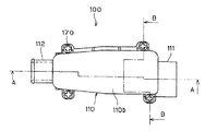
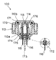
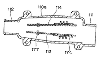
図4〜図8にイオン溶出ユニットの構造を示す。図4は上面図である。図5は垂直断面図で、図4において線A−Aに沿って切断したものである。図6も垂直断面図で、図4において線B−Bに沿って切断したものである。図7は水平断面図である。図8は電極の斜視図である。
【0086】
イオン溶出ユニット100は透明又は半透明の合成樹脂(無色又は着色)、あるいは不透明の合成樹脂からなるケース110を有する。ケース110は上面の開口したケース本体110aとその上面開口を閉ざす蓋110bとにより構成される(図5参照)。ケース本体110aは細長い形状を有しており、長手方向の一方の端に水の流入口111、他方の端に水の流出口112を備える。流入口111と流出口112はいずれもパイプ形状をなす。流出口112の断面積は流入口111の断面積より小さい。
【0087】
ケース110は長手方向を水平方向として配置されるものであるが、このように水平に配置されたケース本体110aの底面は、流出口112に向かい次第に下がる傾斜面となっている(図5参照)。すなわち流出口112はケース110の内部空間において最も低位に設けられている。
【0088】
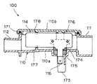
蓋110bは4本のネジ170によりケース本体110aに固定される(図4参照)。ケース本体110aと蓋110bの間にはシールリング171が挟み込まれている(図5参照)。
【0089】
ケース110の内部には、流入口111から流出口112へと向かう水流に沿う形で、2枚の板状電極113、114が向かい合わせに配置されている。ケース110の中に水が存在する状態で電極113、114に所定の電圧を印加すると、電極113、114の陽極側から電極構成金属の金属イオンが溶出する。電極113、114は、一例として、2cm×5cm、厚さ1mm程度の銀プレートを約5mmの距離を隔てて配置する構成とすることができる。
【0090】
電極113、114の材料は銀に限られない。抗菌性を有する金属イオンのもとになる金属であればよい。銀の他、銅、銀と銅の合金、亜鉛などが選択可能である。銀電極から溶出する銀イオン、銅電極から溶出する銅イオン、及び亜鉛電極から溶出する亜鉛イオンは優れた殺菌効果や防カビ効果を発揮する。銀と銅の合金からは銀イオンと銅イオンを同時に溶出させることができる。
【0091】
イオン溶出ユニット100では、電圧の印加の有無で金属イオンの溶出/非溶出を選択できる。また電流や電圧印加時間を制御することにより金属イオンの溶出量を制御できる。ゼオライトなどの金属イオン担持体から金属イオンを溶出させる方式と比較した場合、金属イオンを投入するかどうかの選択や金属イオンの濃度の調節をすべて電気的に行えるので使い勝手がよい。
【0092】
電極113、114は完全に平行に配置されている訳ではない。平面的に見ると、ケース110内を流れる水流に関し、上流側から下流側に向かって、言い換えれば流入口111から流出口112の方向に向かって、電極間の間隔が狭くなるように、テーパ状に配置されている(図7参照)。
【0093】
ケース本体110aの平面形状も、流入口111の存在する端から流出口112の存在する端に向けて絞り込まれている。すなわちケース110の内部空間の断面積は上流側から下流側に向かって漸減する。
【0094】
電極113、114は正面形状長方形であり、各々端子115、116が設けられる。端子115、116はそれぞれ電極113、114の下縁から垂下する形で、上流側となる電極端より内側に入り込んだ箇所に形設される。
【0095】
電極113と端子115、及び電極114と端子116はそれぞれ同一の金属素材により一体成形される。電極115、116はケース本体110aの底壁に設けた貫通孔を通じてケース本体110aの下面に導出される。端子115、116がケース本体110aを突き抜ける箇所には、図6の図中拡大図に見られるように水密シール172の処理が施される。水密シール172は後述する第2のスリーブ175とともに二重のシール構造を形成し、ここからの水もれを防ぐ。
【0096】
ケース本体110aの下面には、端子115、116を隔てる絶縁壁173が一体成形されている(図6参照)。端子115、116は図示しないケーブルを介して制御部80に付属する駆動回路に接続される。
【0097】
端子115、116のうち、ケース110の中に残っている部分は絶縁物質製のスリーブで保護される。2種類のスリーブが使用される。第1のスリーブ174は合成樹脂製であって、端子115、116の付け根部分に嵌合される。第1のスリーブ174はその一部が電極113、114の一方の側面に張り出す形になっており、この部分の側面に突起を形設し、この突起を電極113、114に設けた透孔に係合させている(図6、7参照)。これにより、スリーブ174からの電極113、114の脱落が防がれている。第2のスリーブ175は軟質ゴム製で、第1のスリーブ174とケース本体110aの底壁との隙間を埋めるとともに、自身とケース本体110aとの隙間、及び自身と電極113、114との隙間からの水もれを防ぐ。
【0098】
前述のように端子115、116は電極113、114において上流側の箇所にあり、端子115、116に嵌合される第1のスリーブ174により電極113、114の上流側の部分の支えが構成される。蓋110bの内面には第1のスリーブ174の位置に合わせてフォーク形状の支持部176が形設されており(図6参照)、この支持部176が第1のスリーブ174の上縁を挟み、第2のスリーブ175が第1のスリーブ174とケース本体110aとの隙間を埋めていることと相まって、しっかりとした支えを構成する。なおフォーク形状の支持部176は長短の指で電極113、114を挟み、これにより蓋110bの側でも電極113、114の間隔が適切に保たれるようになっている。
【0099】
電極113、114の下流側の部分もケース110の内面に設けた支持部により支えられる。ケース本体110aの底壁からはフォーク形状の支持部177が立ち上がり、蓋110bの天井面からは同じくフォーク形状の支持部178が、支持部177に向かい合う形で垂下している(図5、8参照)。電極113、114はそれぞれ下流側部分の下縁と上縁を支持部177、178で挟まれ、動かないように保持される。
【0100】
図7に見られるように、電極113、114は、互いに対向する面と反対側の面が、ケース110の内面との間に空間を生じる形で配置されている。また図5に見られるように、電極113、114はその上縁及び下縁とケース110の内面との間にも空間が生じるように配置されている(支持部176、177、178との接触部分は例外)。さらに、図7と図5のいずれにも見られるように、電極113、114の上流側及び下流側の縁とケース110の内面との間にも空間が置かれている。
【0101】
なおケース110の幅をもっと狭くせざるを得ない場合は、電極113、114の、互いに対向する側の面と反対側の面をケース110の内壁に密着させるような構成も可能である。
【0102】
電極113、114に異物が接触しないようにするため、電極113、114の上流側に金網製のストレーナーを配置する。実施形態の場合、図2に示すように、接続管51の中にストレーナー180が設けられている。ストレーナー180は給水弁50の中に異物が入り込まないようにするためのものであるが、イオン溶出ユニット100の上流側ストレーナーも兼ねる。
【0103】
電極113、114の下流側にも金網製のストレーナー181を配置する。ストレーナー181は長期間の使用により電極113、114がやせ細ったとき、それが折れて破片が流失するのを防ぐ。ストレーナー181の配置場所としては、例えば流出口112を選択することができる。
【0104】
ストレーナー180、181の配置場所は上記の場所に限定されない。「電極の上流側」「電極の下流側」という条件を満たしさえすれば、給水経路中のどこに配置してもよい。なおストレーナー180、181は取り外し可能とし、捕捉した異物を除去したり、目詰まりの原因物質を清掃したりすることができるようにする。
【0105】
図9に示すのはイオン溶出ユニット100の駆動回路120である。商用電源121にトランス122が接続され、100Vを所定の電圧に降圧する。トランス122の出力電圧は全波整流回路123によって整流された後、定電圧回路124で定電圧とされる。定電圧回路124には定電流回路125が接続されている。定電流回路125は後述する電極駆動回路150に対し、電極駆動回路150内の抵抗値の変化にかかわらず一定の電流を供給するように動作する。
【0106】
商用電源121にはトランス122と並列に整流ダイオード126が接続される。整流ダイオード126の出力電圧はコンデンサ127によって平滑化された後、定電圧回路128によって定電圧とされ、マイクロコンピュータ130に供給される。マイクロコンピュータ130はトランス122の一次側コイルの一端と商用電源121との間に接続されたトライアック129を起動制御する。
【0107】
電極駆動回路150はNPN型トランジスタQ1〜Q4とダイオードD1、D2、抵抗R1〜R7を図のように接続して構成されている。トランジスタQ1とダイオードD1はフォトカプラ151を構成し、トランジスタQ2とダイオードD2はフォトカプラ152を構成する。すなわちダイオードD1、D2はフォトダイオードであり、トランジスタQ1、Q2はフォトトランジスタである。
【0108】
今、マイクロコンピュータ130からラインL1にハイレベルの電圧、ラインL2にローレベルの電圧又はOFF(ゼロ電圧)が与えられると、ダイオードD2がONになり、それに付随してトランジスタQ2もONになる。トランジスタQ2がONになると抵抗R3、R4、R7に電流が流れ、トランジスタQ3のベースにバイアスがかかり、トランジスタQ3はONになる。
【0109】
一方、ダイオードD1はOFFなのでトランジスタQ1はOFF、トランジスタQ4もOFFとなる。この状態では、陽極側の電極113から陰極側の電極114に向かって電流が流れる。これによってイオン溶出ユニット100には陽イオンの金属イオンと陰イオンとが発生する。
【0110】
イオン溶出ユニット100に長時間一方向に電流を流すと、図9で陽極側となっている電極113が減耗するとともに、陰極側となっている電極114には水中のカルシウムなどの不純物がスケールとして固着する。また電極の成分金属の塩化物及び硫化物が電極表面に発生する。これはイオン溶出ユニット100の性能低下をもたらすので、電極の極性を反転して電極駆動回路150を運転できるように構成されている。
【0111】
電極の極性を反転するにあたっては、ラインL1、L2の電圧を逆にして、電極113、114を逆方向に電流が流れるようにマイクロコンピュータ130が制御を切り替える。この場合、トランジスタQ1、Q4がON、トランジスタQ2、Q3がOFFとなる。マイクロコンピュータ130はカウンタ機能を有していて、所定カウント数に達する度に上述の切り替えを行う。
【0112】
電極駆動回路150内の抵抗の変化、特に電極113、114の抵抗変化によって、電極間を流れる電流値が減少するなどの事態が生じた場合は、定電流回路125がその出力電圧を上げ、電流の減少を防止する。しかしながら、累積使用時間が長くなるとイオン溶出ユニット100が寿命を迎え、電極の極性反転や、特定極性である時間を平時よりも長くして電極に付着した不純物を強制に取り除く電極洗浄モードへの切り替えや、定電流回路125の出力電圧上昇を実施しても、電流減少を防げなくなる。
【0113】
そこで本回路では、イオン溶出ユニット100の電極113、114間を流れる電流を抵抗R7に生じる電圧によって監視し、その電流が所定の最小電流値に至ると、それを電流検知手段が検出するようにしている。電流検知回路160がその電流検知手段である。最小電流値を検出したという情報はフォトカプラ163を構成するフォトダイオードD3からフォトトランジスタQ5を介してマイクロコンピュータ130に伝達される。マイクロコンピュータ130は線路L3を介して報知手段を駆動し、所定の警告報知を行わせる。警告報知手段131がその報知手段である。警告報知手段131は操作/表示部81又は制御部80に配置されている。
【0114】
また、電極駆動回路150内でのショートなどの事故については、電流が所定の最大電流値以上になったことを検出する電流検知手段が用意されており、この電流検知手段の出力に基づいてマイクロコンピュータ130は警告報知手段131を駆動する。電流検知回路161がその電流検知手段である。さらに、定電流回路125の出力電圧が予め定めた最小値以下になると、電圧検知回路162がこれを検知し、同様にマイクロコンピュータ130が警告報知手段131を駆動する。
【0115】
イオン溶出ユニット100の生成した金属イオンは、次のようにして洗濯槽30に投入される。
【0116】
金属イオン及び仕上剤として用いられる柔軟剤は最終すすぎの段階で投入される。図14は最終すすぎのシーケンスを示すフローチャートである。最終すすぎでは、ステップS500の脱水工程の後、ステップS420に進む。ステップS420では仕上物質の投入が選択されているかどうかを確認する。操作/表示部81による設定作業で「仕上物質の投入」が選択されていればステップS421に進む。選択されていなければ図12のステップS401に進み、それまでのすすぎ工程と同様のやり方で最終すすぎを遂行する。
【0117】
ステップS421では投入すべき仕上物質が金属イオンと柔軟剤の2種類であるかどうかを確認する。操作/表示部81による設定作業で「金属イオンと柔軟剤」が選択されていればステップS422に進む。選択されていなければステップS426に進む。
【0118】
ステップS422ではメイン給水弁50aとサブ給水弁50bの両方が開き、メイン給水経路52aとサブ給水経路52bの両方に水が流れる。
【0119】
ステップS422は金属イオン溶出工程である。メイン給水弁50aに設定された、サブ給水弁50bに設定された水量よりも多い所定の水量の水流がイオン溶出ユニット100の内部空間を満たしつつ流れる。それと同時に駆動回路120が電極113、114の間に電圧を印加し、電極構成金属のイオンを水中に溶出させる。電極構成金属が銀の場合、陽極側の電極においてAg→Ag++e−の反応が生じ、水中に銀イオンAg+が溶出する。電極間を流れる電流は直流である。金属イオンを添加された水は洗剤室54に入り、注水口54aから注水口56を経て洗濯槽30に注ぎ込まれる。
【0120】
サブ給水弁50bからはメイン給水弁50aから流れ出すのよりも少量の水が流れ出し、サブ給水経路52bを通じて仕上剤室55に注ぎ込まれる。仕上剤室55に仕上剤(柔軟剤)が入れられていれば、その仕上剤(柔軟剤)はサイホン部57から水と共に洗濯槽30に投入される。金属イオンと同時投入ということになる。仕上剤室55の中の水位が所定高さに達してはじめてサイホン効果が生じるので、時期が来て水が仕上剤室55に注入されるまで、液体の仕上剤(柔軟剤)を仕上剤室55に保持しておくことができる。
【0121】
所定量(サイホン部57にサイホン作用を起こさせるに足る量か、それ以上)の水を仕上剤室55に注入したところでサブ給水弁50bは閉じる。なおこの水の注入工程すなわち仕上剤投入動作は、仕上剤(柔軟剤)が仕上剤室55に入れられているかどうかに関わりなく、「仕上剤の投入」が選択されていれば自動的に実行される。
【0122】
洗濯槽30に所定量の金属イオン添加水が投入され、以後金属イオン非添加水を設定水位まで注げばすすぎ水の金属イオン濃度が所定値に達すると判断されたところで電極113、114への電圧印加は停止する。イオン溶出ユニット100が金属イオンを生成しなくなった後もメイン給水弁50aは給水を続け、洗濯槽30の内部の水位が設定水位に達したところで給水を止める。
【0123】
上記のようにステップS422で金属イオンと仕上剤(柔軟剤)を同時投入するのであるが、これは必ずしも、イオン溶出ユニット100が金属イオンを生成している時間に、サイホン作用で仕上剤(柔軟剤)が洗濯槽30に投入される時間が完全に重ならなければならないということを意味するものではない。どちらかが前後にずれても構わない。イオン溶出ユニット100が金属イオンの生成を停止した後、金属イオン非添加水が追加注水されているときに仕上剤(柔軟剤)が投入されることとしてもよい。要は、一つのシーケンスの中で金属イオンの投入と仕上剤(柔軟剤)の投入がそれぞれ実行されればよい。
【0124】
前述のとおり、端子115は電極113に、端子116は電極114に、それぞれ同一金属素材で一体成形されている。このため、別の金属部品同士を接合した場合と異なり、電極と端子の間に電位差が生じず、腐食が発生することがない。また一体化することにより製造工程を簡略化することができる。
【0125】
電極113、114の間隔は、上流側から下流側に向かって狭くなるようにテーパ状に設定してある。このため電極は水の流れに沿い、減耗して板厚が薄くなったとき、ビビリ振動を生じにくく欠けにくい。また過度に変形して短絡する心配もない。
【0126】
電極113、114はケース110の内面との間に空間を生じる形で支持されている。このため、電極113、114からケース110の内面にかけ金属層が成長し、他方の電極との間に短絡現象を起こすようなことがない。
【0127】
端子115、116が電極113、114と一体であったとしても、使用に伴い電極113、114が減耗するのは仕方がないが、端子115、116が減耗するのは困る。本実施形態の場合、端子115、116のケース110内に位置する部分は絶縁物質製のスリーブ174、175で保護されており、通電による減耗が少ない。このため、使用途中で端子115、116が折れるといった事態が防がれる。
【0128】
電極113、114において、端子115、116が設けられる箇所は上流側の端より内側に入り込んだ箇所である。電極113、114は互いの間隔の狭くなった部分より減耗して行く。端の部分の減耗も早いが、端子115、116は電極113、114の中でも上流側の部分ではあるものの全くの端という訳ではなく、そこから内側に入り込んだ箇所に形設されているので、電極の端から始まった減耗が端子に達して端子が根元から折れてしまうといった事態を心配せずに済む。
【0129】
電極113、114の上流側は第1のスリーブ174と支持部176とにより支持されている。他方電極113、114の下流側は支持部177、178により支持されている。このように上流側と下流側とでしっかり支持されているため、水流の中にあっても電極113、114は振動しない。従って、振動が原因で電極113、114が折れるということがない。
【0130】
端子115、116はケース本体110aの底壁を貫通して下向きに突出する。このため、蒸気がケース110aに接触したり(風呂水を用いて洗濯を行う場合、洗濯機1の内部に蒸気が侵入しやすい)、通水によりケース110が冷やされたりして、ケース110の外面に結露が生じたとしても、結露水は端子115、116に接続したケーブルを伝って流れ落ち、端子115、116とケース110との境界に滞留しない。従って端子115、116の間が結露水で短絡されるといった事態に発展することがない。ケース本体110aは長手方向を水平にして配置されているので、電極113、114の側面に設けた端子115、116をケース本体110aの底壁より下向きに突出させる構成とするのは容易である。
【0131】
イオン溶出ユニット100の流出口112は流入口111よりも断面積が小さく、流路抵抗が大きい。このため、流入口111からケース110の中に入り込んだ水はケース110の内部に空気溜まりをつくることなく満ちあふれ、電極113、114をすっかり浸す。従って、電極113、114の中に金属イオン生成に関与しない箇所が生じ、この箇所が溶け残るといった事態は発生しない。
【0132】
流出口112の断面積が流入口111の断面積より小さいだけでなく、ケース110の内部空間の断面積も上流側から下流側に向かって漸減している。このため、ケース110の内部で乱流や気泡が生じにくく、水流がスムーズになる。気泡が電極に溶け残りを生じさせることもない。金属イオンも速やかに電極113、114を離れ、電極113、114に逆戻りしないので、イオン溶出効率が向上する。
【0133】
イオン溶出ユニット100は流量大であるメイン給水経路52aに配置されていて、流れる水量が多い。このため、金属イオンはすぐにケース110から運び出され、電極113、114に逆戻りしない。従ってイオン溶出効率が向上する。
【0134】
流出口112はケース110の内部空間において最も低位に設けられている。このため、イオン溶出ユニット100への通水を停止したとき、イオン溶出ユニット100の中の水はすべて流出口112から流出する。従って寒冷時にケース110内の残水が凍結し、イオン溶出ユニット100が故障する、あるいは破壊するといった事態は発生しない。
【0135】
電極113、114の上流側にはストレーナー180が存在する。このため、イオン溶出ユニット100に供給される水の中に固形の異物が存在したとしても、その異物はストレーナー180で捕捉され、電極113、114まで届かない。従って異物が電極113、114を傷つけることがなく、また電極間が異物で短絡されて過大な電流が流れたり、金属イオン生成不足になったりすることもない。
【0136】
電極113、114の下流側にはストレーナー181が存在する。長期間の使用により電極113、114が減耗したりもろくなったりし、折れて破片が流出するようなことがあったとしても、その破片はストレーナー181で捕捉され、それより下流には流れて行かない。従って電極113、114の破片が下流側の物品にダメージを与えるようなことがない。
【0137】
本実施形態のようにイオン溶出ユニット100を洗濯機1に搭載している場合、ストレーナー180、181がなければ異物や電極の破片が洗濯物に付着することがあり得る。異物や電極の破片は洗濯物を汚したり傷つけたりする可能性があり、また洗濯物に異物や電極の破片が付着したまま脱水乾燥が行われると、後でその洗濯物を着た人がそれらに触れて不快感を憶えたり、極端な場合は負傷するといった事態に結びつきかねないが、ストレーナー180、181があればそのような事態を避けることができる。
【0138】
なおストレーナー180、181は必ず両方とも配置しなければならないということはない。なくても問題は生じないと判断できればその片方、ないしは両方を廃止することができる。
【0139】
図14のフローチャートに戻って説明を続ける。ステップS423では金属イオンと仕上剤(柔軟剤)が投入されたすすぎ水を強い水流(強水流)で攪拌し、洗濯物と金属イオンとの接触、及び洗濯物への仕上剤(柔軟剤)の付着を促進する。
【0140】
強水流で十分に攪拌を行うことにより、金属イオンと仕上剤(柔軟剤)を水に均一に溶け込ませ、洗濯物の隅々にまで行き渡らせることができる。所定時間の間強水流で攪拌を行った後、ステップS424に進む。
【0141】
ステップS424では一転して弱い水流(弱水流)での攪拌となる。金属イオンを洗濯物の表面に付着させ、その効果を発揮させるのがねらいである。弱いながらも水流が生じていれば、洗濯機1の運転が終了してしまったと使用者が誤解するおそれがないため、ゆるやかに攪拌を行う。しかしながら、すすぎ工程の途中であることを使用者に認識させる手だてがあれば、例えば操作/表示部81に表示を出して使用者の注意を喚起することができれば、攪拌をやめ、水を静止状態に置いても構わない。
【0142】
洗濯物が金属イオンを吸着するのに十分な程度に設定した弱水流期間の後、ステップS425に進む。ここでは再び強い水流(強水流)で念押しの攪拌を行う。これにより、洗濯物の中で金属イオンの行き渡っていなかった箇所にまで金属イオンを送り込み、しっかりと付着させる。
【0143】
ステップS425の後、ステップS406に移る。ステップS406ではパルセータ33が小刻みに反転して洗濯物をほぐす。これにより洗濯槽30の中に洗濯物がバランス良く配分されるようにし、脱水回転に備える。
【0144】
各ステップの時間配分の一例を掲げる。ステップS423(強水流)は4分、ステップS424(弱水流)は4分15秒、ステップS425(強水流)は5秒、及びステップS406(バランス)は1分40秒とする。ステップS423からステップ406までのトータル時間は10分となる。
【0145】
金属イオンと仕上剤(柔軟剤)とは、本来は別々に投入するのが望ましい。というのは、金属イオンが柔軟剤成分に接触すると化合物に変化し、金属イオンによる抗菌効果が減殺されるからである。しかしながら、すすぎ水の中にはかなりの量の金属イオンが最後まで残り続ける。また効果減殺分は金属イオンの濃度設定によりある程度補償可能である。そこで、金属イオンと仕上剤(柔軟剤)を同時投入し、抗菌性付与の効果は多少低下するものの、別々に投入してそれぞれにすすぎを行う場合に比べてすすぎ時間を短縮し、家事の効率化を図ったものである。
【0146】
金属イオンと仕上剤(柔軟剤)が洗濯槽30の中で出会うのは仕方がないにせよ、洗濯槽30に入るまでは接触を避けるのが望ましい。本実施形態の場合、金属イオンはメイン給水経路52aから洗剤室54を通って洗濯槽30に投入される。仕上剤(柔軟剤)は仕上剤室55から洗濯槽30に投入される。このように金属イオンをすすぎ水に投入するための経路と、仕上剤をすすぎ水に投入するための経路とが別系統のため、洗濯槽30の中で出会うまでは金属イオンと仕上剤(柔軟剤)との接触は生じず、金属イオンが高濃度の仕上剤(柔軟剤)に接触して化合物となり、抗菌力を失うということがない。
【0147】
なお、最終すすぎの場合にも洗濯槽30の中にすすぎ水をためておいてすすぎを行う「ためすすぎ」を実行するものとして説明を進めたが、「注水すすぎ」で最終すすぎを行ってもよい。その場合、注ぎかける水は金属イオン添加水であるものとする。
【0148】
また、ステップS406でうまくバランスがとれず、もう一度水を注いで「バランス修正すすぎ」を行う場合にも金属イオン添加水を使用するものとする。
【0149】
さて、第1の仕上物質である金属イオンの投入と第2の仕上物質である仕上剤(柔軟剤)の投入はいずれも任意選択事項である。一方の投入をやめることもできるし、両方とも投入をやめることもできる。両方とも投入をやめる場合はステップS420からステップS401に進むことになるが、これについては前に述べた。ここからは2種類の仕上物質のうち一方だけを投入する場合について説明する。
【0150】
ステップS421において、投入すべき仕上物質が金属イオンと柔軟剤の2種類でないとなれば、その一方のみの投入が選択されているということである。この場合はステップS426に進む。
【0151】
ステップS426では、投入すべき仕上物質が金属イオンであるかどうかを確認する。金属イオンであればステップS427に進む。そうでなければステップS428に進む。
【0152】
ステップS427ではメイン給水弁50aが開き、メイン給水経路52aに水が流れる。サブ給水弁50bは開かない。イオン溶出ユニット100に水が流れると、駆動回路120が電極113、114の間に電圧を印加し、電極構成金属のイオンを水中に溶出させる。洗濯槽30に所定量の金属イオン添加水が投入され、以後金属イオン非添加水を設定水位まで注げばすすぎ水の金属イオン濃度が所定値に達すると判断されたところで電極113、114への電圧印加は停止する。イオン溶出ユニット100が金属イオンを生成しなくなった後もメイン給水弁50aは給水を続け、洗濯槽30の内部の水位が設定水位に達したところで給水を止める。
【0153】
ステップS427の後、ステップS423に進む。以後、金属イオンと仕上剤(柔軟剤)を同時投入したときと同じようにステップS423(強水流)→ステップS424(弱水流)→ステップS425(強水流)→ステップS406(バランス)と進む。
【0154】
ステップS426で、投入すべき仕上物質が金属イオンではないとなった場合には、仕上剤(柔軟剤)が単独で投入されるということである。このときはステップS428に進む。
【0155】
ステップS428ではメイン給水弁50aとサブ給水弁50bの両方が開き、メイン給水経路52aとサブ給水経路52bの両方に水が流れる。ただしイオン溶出ユニット100は駆動されず、金属イオンの生成は行われない。サイホン作用を起こさせるに十分な水が仕上剤室55に注ぎ込まれ、仕上剤(柔軟剤)がサイホン部57を通じて洗濯槽30に投入された後は、サブ給水弁50bは閉じる。
【0156】
メイン給水弁50aはサブ給水弁50bが閉じた後も給水を続け、洗濯槽30の内部の水位が設定水位に達したところで給水を止める。
【0157】
ステップS428の後、ステップS423に進む。以後、金属イオンと仕上剤(柔軟剤)を同時投入したときと同じようにステップS423(強水流)→ステップS424(弱水流)→ステップS425(強水流)→ステップS406(バランス)と進む。
【0158】
このように、仕上物質を1種類しか投入しない場合でも強水流→弱水流→強水流の各ステップを実行し、仕上物質が確実に洗濯物に付着するようにする。ただし各ステップの時間配分は、金属イオンと仕上剤(柔軟剤)とで同じである必要はないので、それぞれに適合するように調整して設定する。
【0159】
仕上剤(柔軟剤)の場合、洗濯物に付着させるのに金属イオンのように長い時間をかける必要がない。そこで、ステップS428の後にステップS423(強水流)とS406(バランス)のみを置き、ステップS423(強水流)も例えば2分間といった短い時間で済ませることが可能である。
【0160】
イオン溶出ユニット100を駆動するにあたり、駆動回路120の定電流回路125は電極113、114間を流れる電流が値一定となるよう電圧を制御する。これにより、単位時間あたりの金属イオン溶出量が一定になる。単位時間あたりの金属イオン溶出量が一定であれば、イオン溶出ユニット100に流す水量とイオン溶出時間を制御することにより洗濯槽30内の金属イオン濃度を制御することができることになり、所望の金属イオン濃度を得るのが容易になる。
【0161】
この時電極113、114間を流れる電流は直流である。もしこれが交流であると、次の現象が起きる。すなわち、金属イオンが例えば銀イオンの場合、一旦溶出した銀イオンが、電極の極性が反転したときに、Ag++e−→Agという逆反応によって電極に戻ってしまう。直流であればそのようなことはない。
【0162】
電極113、114の内、陰極として使用される側にはスケールが析出する。極性を反転しないまま直流を流し続け、スケールの堆積量が多くなると、電流が流れにくくなり、金属イオンを所定レートで溶出することが難しくなる。また陽極として使用される電極だけ減耗が早まる「片減り」の問題も発生する。そこで、電極113、114の極性は周期的に反転させる。
【0163】
電極113、114は金属イオンの溶出を続けるうちに次第に減耗し、金属イオンの溶出量が減少する。使用が長期にわたれば金属イオンの溶出量が不安定になったり、所定の溶出量を確保できなくなったりする。そのため、イオン溶出ユニット100は交換可能とされ、電極113、114の寿命が来れば新しいユニットに交換できるようになっている。さらに、電極113、114が耐用限界に達したことを操作/表示部81を通じて使用者に報知し、イオン溶出ユニット100の交換などのメンテナンスを促すようになっている。
【0164】
以上、本発明の実施形態につき説明したが、本発明の範囲はこれに限定されるものではなく、発明の主旨を逸脱しない範囲で種々の変更を加えて実施することができる。
【0165】
また本発明は、洗濯機以外の機器、例えば食器洗浄機や加湿機に応用可能である。洗濯機にしても、上記実施形態でとり上げたような形式の全自動洗濯機の他、横型ドラム(タンブラー方式)、斜めドラム、乾燥機兼用のもの、又は二層式など、あらゆる形式の洗濯機に応用可能である。
【0166】
【発明の効果】
本発明のイオン溶出ユニットによれば、供給される水の中に固形の異物が存在したとしても、その異物は上流側のストレーナーで捕捉されるから、異物が電極を傷つけることがなく、また電極間が異物で短絡されて過大な電流が流れたり、金属イオン生成不足になったりすることもない。また長期間の使用により電極が減耗したりもろくなったりし、折れて破片が流出するようなことがあったとしても、その破片は下流側のストレーナーで捕捉され、それより下流には流れて行かない。従って電極の破片が下流側の物品にダメージを与えるようなことがない。
【0167】
このようなイオン溶出ユニットを機器に搭載することにより、イオン溶出ユニットの生成した金属イオンを水に添加して用い、洗濯機であれば洗濯物における細菌やカビの繁殖の防止、機器が食器洗浄機であれば食器の衛生度向上、加湿機であれば細菌や藻類の胞子などが空気中に飛散することの防止といった効果を得ることができる。そして前記ストレーナーの存在により、機器を安定して、且つ安全に使用することができる。
【0168】
さらに、イオン溶出ユニットを機器に搭載するにあたり、機器に設定される流量大のメイン給水経路と流量小のサブ給水経路のうち、メイン給水経路にイオン溶出ユニットを配置したから、イオン溶出ユニットには流量大の水流が流れて金属イオンを運び去ることになり、金属イオンが電極に逆戻りすることがなく、イオン溶出ユニットを効率良く稼働することができる。
【0169】
また、電極間に電圧を印加して金属イオンを生成するイオン溶出ユニットを搭載し、このイオン溶出ユニットの生成した金属イオンを水に添加して用いる洗濯機において、洗濯槽に水を注ぐ給水口の上流、且つ給水弁の下流の位置にイオン溶出ユニットを配置し、給水弁からの水をイオン溶出ユニットを介して給水口に供給するとともに、給水口に洗剤室を設けるものとすることにより、洗剤を含んだ水がイオン溶出ユニットの中を通ったり、あるいは洗剤を含んだ水が洗剤室の方から逆流するといったことを防ぐことができ、洗剤成分が電極に接触してスケールの形で付着し、イオン溶出ユニットの性能低下を招くといった事態を招くことがない。
【図面の簡単な説明】
【図1】本発明の一実施形態に係る洗濯機の垂直断面図
【図2】給水口の模型的垂直断面図
【図3】洗濯機内部の部分上面図
【図4】イオン溶出ユニットの上面図
【図5】図4のA−A線に沿って切断した垂直断面図
【図6】図4のB−B線に沿って切断した垂直断面図
【図7】イオン溶出ユニットの水平断面図
【図8】電極の斜視図
【図9】イオン溶出ユニットの駆動回路図
【図10】洗濯工程全体のフローチャート
【図11】洗い工程のフローチャート
【図12】すすぎ工程のフローチャート
【図13】脱水工程のフローチャート
【図14】最終すすぎ工程のフローチャート
【符号の説明】
1 洗濯機
10 外箱
20 水槽
30 洗濯槽
33 パルセータ
40 駆動ユニット
50 給水弁
50a メイン給水弁
50b サブ給水弁
53 給水口
54 洗剤室
55 仕上剤室
68 排水弁
80 制御部
81 操作/表示部
100 イオン溶出ユニット
113、114 電極
120 駆動回路
125 定電流回路
150 電極駆動回路
180、181 ストレーナー[0001]
TECHNICAL FIELD OF THE INVENTION
The present invention relates to an ion elution unit that elutes metal ions having an antibacterial action into water, and an apparatus that uses the metal ions generated by the ion elution unit added to water. The equipment particularly relates to a washing machine.
[0002]
[Prior art]
When washing in a washing machine, it is common to add a finishing substance to water, in particular to rinsing water. Common finishing materials are softeners and glues. In addition, recently, there is an increasing need for a finishing treatment for imparting antibacterial properties to laundry.
[0003]
It is desirable that the laundry be sun-dried from a sanitary viewpoint. However, in recent years, the number of families who have no one at home during the daytime has increased due to the increase in the female employment rate and the progress of nuclear families. In such a home, you have to rely on indoor drying. Even in a home where somebody is at home during the day, when it rains, it will dry indoors.
[0004]
In the case of indoor drying, bacteria and mold are more likely to propagate on the laundry than in the case of sun drying. This tendency is remarkable when it takes a long time to dry the laundry, such as at a high humidity or a low temperature such as during the rainy season. Depending on the breeding situation, the laundry may give off a bad smell. For this reason, in households that are forced to dry indoors on a daily basis, there is a strong demand for antibacterial treatment of cloths in order to suppress the growth of bacteria and mold.
[0005]
In recent years, there has been an increase in the number of garments that have been subjected to antibacterial and deodorant treatments and bacteriostatic treatments. However, it is difficult to prepare all household textiles with antibacterial and deodorized products. In addition, the effect of antibacterial and deodorant processing decreases as washing is repeated.
[0006]
This led to the idea of treating laundry with antibacterial treatment each time it was washed. For example, Patent Literature 1 describes an electric washing machine equipped with an ion generator that generates metal ions having sterilizing power such as silver ions and copper ions. Patent Literature 2 discloses a washing machine configured to sterilize a cleaning liquid by generating an electric field. Patent Literature 3 discloses a washing machine including a silver ion addition unit that adds silver ions to washing water.
[0007]
[Patent Document 1]
Japanese Utility Model Publication No. 5-74487 [Patent Document 2]
Japanese Patent Application Laid-Open No. 2000-93691 [Patent Document 3]
JP 2001-276484 A
[Problems to be solved by the invention]
INDUSTRIAL APPLICABILITY The present invention provides an ion elution unit used for obtaining metal ions having an antibacterial action, which can be used without damaging the electrode, and which does not affect the downstream side even if the electrode is chipped off. The purpose is to provide a unit. Furthermore, by using the metal ions generated by the ion eluting unit in water, it is possible to avoid the adverse effects caused by the propagation of bacteria, not to damage the ion eluting unit, and to efficiently use the ion eluting unit. An object of the present invention is to provide a device that can operate, particularly a washing machine. Furthermore, by providing an ion elution unit upstream of the detergent chamber where the detergent is mixed with water, water containing the detergent is prevented from passing through the ion elution unit. It is an object of the present invention to provide a washing machine in which the performance of the unit is not reduced.
[0009]
[Means for Solving the Problems]
In order to achieve the above object, in the present invention, the ion elution unit is configured as follows.
[0010]
(1) In an ion elution unit that generates metal ions by applying a voltage between the electrodes, a strainer is disposed upstream of the electrodes.
[0011]
According to this configuration, even if solid foreign matter is present in the water supplied to the ion elution unit, the foreign matter is captured by the strainer and does not reach the electrode. Therefore, the foreign matter does not damage the electrodes, and the electrodes are not short-circuited by the foreign matter, so that an excessive current does not flow or insufficient generation of metal ions occurs.
[0012]
(2) In an ion elution unit that generates metal ions by applying a voltage between the electrodes, a strainer is disposed downstream of the electrodes.
[0013]
According to this configuration, even if the electrodes are worn out or become fragile due to long-term use, and the pieces may break and break out, the pieces are captured by the strainer and flow downstream. Don't go. Therefore, the fragments of the electrode do not damage the downstream articles.
[0014]
(3) In an ion elution unit that generates metal ions by applying a voltage between the electrodes, strainers are arranged on the upstream and downstream sides of the electrodes.
[0015]
According to this configuration, even if solid foreign matter is present in the water supplied to the ion elution unit, the foreign matter is captured by the strainer on the upstream side and does not reach the electrode. Therefore, the foreign matter does not damage the electrodes, and an excessive current does not flow due to the short-circuit between the electrodes due to the foreign matter, and the generation of metal ions does not become insufficient. Also, even if the electrodes are worn or fragile due to long-term use, or broken, and fragments may flow out, the fragments are captured by the strainer and do not flow downstream. Therefore, the fragments of the electrode do not damage the downstream articles.
[0016]
Further, in the present invention, the device is configured as follows.
[0017]
(4) The above-described ion elution unit is mounted on a device, and the metal ions generated by the ion elution unit are added to water for use.
[0018]
According to this configuration, since the metal ions generated by the ion eluting unit can be used by adding to water, for example, when the machine is a washing machine, the laundry is subjected to antibacterial treatment with the metal ions to propagate bacteria and mold. And the generation of offensive odor can be prevented. If the equipment is a dishwasher, the tableware can be treated with metal ions for antibacterial treatment to improve the hygiene. If the equipment is a humidifier, it prevents bacteria and algae from propagating in the water in the water tank. Can be prevented.
[0019]
When a strainer is arranged upstream of the electrode, even if solid foreign matter is present in the water supplied to the ion elution unit, the foreign matter is caught by the strainer and damages the electrodes or creates a gap between the electrodes. The ion elution unit can be stably operated in the device without causing a short circuit. If a strainer is placed downstream of the electrode, even if the electrode is worn or fragile due to long-term use, and may break and leak fragments, the fragments are captured by the strainer. It does not flow downstream. Therefore, the fragments of the electrode do not damage the downstream articles.
[0020]
(5) In the above device, the device is a washing machine.
[0021]
According to this configuration, it is possible to prevent foreign matter and electrode fragments contained in water from adhering to the laundry and soiling or damaging the laundry. In addition, dehydration and drying are performed in a state in which foreign matter and electrode fragments remain attached, and a situation in which a person wearing the laundry later touches the foreign material or electrode fragments and feels uncomfortable or is injured does not occur. .
[0022]
(6) An ion elution unit for generating metal ions by applying a voltage between the electrodes is mounted on a device, and the metal ions generated by the ion elution unit can be added to water for use. The ion elution unit was connected to the downstream side of the water supply valve provided in the above, and the strainer provided in the water supply valve was also used as the upstream strainer of the ion elution unit.
[0023]
According to this configuration, the strainer that prevents foreign matter from entering the water supply valve also prevents foreign matter from entering the ion elution unit. Therefore, there is no need to separately prepare a strainer for disposing the strainer on the upstream side of the ion elution unit, and the configuration of the apparatus is simplified and the cost can be reduced.
[0024]
(7) In the apparatus as described above, the apparatus is a washing machine.
[0025]
According to this configuration, no foreign matter enters from the water supply valve and does not damage the water supply valve itself or the ion elution unit downstream thereof. Foreign matter and electrode fragments contained in the water do not adhere to the laundry, and the laundry does not become dirty or damaged. In addition, dehydration and drying are performed in a state in which the foreign matter and the pieces of the electrode are still attached, and a situation in which a person wearing the later touches the foreign matter and feels uncomfortable or injured does not occur.
[0026]
(8) The ion elution unit as described above is mounted on a device so that the metal ions generated by the ion elution unit can be added to water and used, and the main water supply path with a large flow rate and the flow A small sub water supply path was set, and the ion elution unit was arranged in the main water supply path.
[0027]
According to this configuration, the large flow water flow and the small flow water flow can be selectively used as necessary in the device, and the high flow water flow flows through the ion elution unit to carry away the metal ions. Does not return to the electrode. Therefore, the ion elution unit can be operated efficiently.
[0028]
(9) In the equipment as described above, the equipment is a washing machine.
[0029]
According to this configuration, the high-flow water flow and the low-flow water flow can be selectively used as needed, and the high-flow water flow flows through the ion elution unit to carry away the metal ions. There is no going back. Therefore, metal ions necessary for antibacterial treatment of laundry can be efficiently generated.
[0030]
(10) As described above, in the case where the appliance is a washing machine, a detergent room and a finish agent room are defined at a water supply port for pouring water into a washing tub, and water from the main water supply path is introduced into the detergent room. Water from the sub-water supply path was introduced into the finishing agent chamber.
[0031]
According to this configuration, the path for introducing the metal ions into the washing tub and the path for introducing the finishing agent into the washing tub are separate systems, and the high concentration of the high concentration existing in the path for introducing the finishing agent is provided. There is no loss of antibacterial activity due to metal ions coming into contact with the finish to form compounds.
[0032]
(11) In the apparatus as described above, the ion elution unit includes a water inlet at one end in the longitudinal direction of the case and a water outlet at the other end, and makes the longitudinal direction of the case substantially horizontal. It was assumed to be arranged.
[0033]
According to this configuration, the ion elution unit and the water pipe for the ion elution unit can be arranged in a compact form without being bulky in the height direction.
[0034]
(12) A washing machine in which an ion eluting unit for generating metal ions by applying a voltage between the electrodes is mounted, and water is poured into a washing tub in a washing machine using the metal ions generated by the ion eluting unit added to water. The ion elution unit is arranged at a position upstream of the mouth and downstream of the water supply valve, and water from the water supply valve is supplied to the water supply port through the ion elution unit, and a detergent chamber is provided at the water supply port. It was taken.
[0035]
According to this configuration, since the ion eluting unit is located upstream of the detergent chamber for mixing the detergent with water, the water containing the detergent passes through the ion eluting unit, or the water containing the detergent flows in the detergent chamber. There is no backflow from the direction. Therefore, the detergent component does not come into contact with the electrode and adheres in the form of a scale, which does not cause a situation in which the performance of the ion elution unit is reduced.
[0036]
BEST MODE FOR CARRYING OUT THE INVENTION
Hereinafter, embodiments of the present invention will be described with reference to the drawings.
[0037]
FIG. 1 is a vertical sectional view showing the entire configuration of the washing machine 1. The washing machine 1 is of a fully automatic type and includes an outer box 10. The outer box 10 has a rectangular parallelepiped shape and is formed of metal or synthetic resin, and the upper and lower surfaces thereof have openings. An upper surface plate 11 made of synthetic resin is stacked on the upper surface opening of the outer case 10 and fixed to the outer case 10 with screws. In FIG. 1, the left side is the front of the washing machine 1 and the right side is the back. A
[0038]
At four corners of the
[0039]
A
[0040]
A
[0041]
The washing tub 30 has a peripheral wall that extends upward and has a gentle taper. Except for a plurality of dehydration holes 31 arranged annularly at the top of this peripheral wall, there is no opening through which liquid passes. That is, the washing tub 30 is a so-called “holeless” type. At the edge of the upper opening of the washing tub 30, an
[0042]
The
[0043]
A
[0044]
FIG. 2 is a schematic vertical sectional view of the
[0045]
The siphon
[0046]
The
[0047]
The main
[0048]
In some washing machines, a water supply valve is not divided into a main water supply valve and a sub water supply valve, and a water supply port has only a detergent room but no finish agent room. In such a washing machine, all the water from the water supply valve will be poured into the detergent room.
[0049]
Returning to FIG. 1, the description will be continued. A
[0050]
An
[0051]
The
[0052]
A
[0053]
The operation of the washing machine 1 will be described. The
[0054]
After the preparation for the introduction of the detergent and the finishing agent (softening agent) is completed, the
[0055]
FIG. 10 is a flowchart showing the entire washing process. In step S201, it is determined whether or not a reserved driving operation for starting washing at a set time has been selected. If the reserved operation has been selected, the process proceeds to step S206. If not, the process proceeds to step S202.
[0056]
When the process proceeds to step S206, it is confirmed whether or not the operation start time has come. When the operation start time comes, the process proceeds to step S202.
[0057]
In step S202, it is confirmed whether a washing step has been selected. If the selection has been made, the process proceeds to step S300. The contents of the washing step in step S300 will be described separately with reference to the flowchart in FIG. After the completion of the washing process, the process proceeds to step S203. If the washing process has not been selected, the process immediately proceeds from step S202 to step S203.
[0058]
In step S203, it is confirmed whether or not the rinsing process has been selected. If it has been selected, the process proceeds to step S400. The contents of the rinsing step of step S400 will be described separately with reference to the flowchart of FIG. In FIG. 10, the rinsing process is performed three times, and the step numbers of each time are denoted by branch numbers “S400-1,” “S400-2,” and “S400-3”. The user can arbitrarily set the number of times of the rinsing step. In this case, “S400-3” is the final rinsing step.
[0059]
After the end of the rinsing step, the process proceeds to step S204. If the rinsing process has not been selected, the process immediately proceeds from step S203 to step S204.
[0060]
In step S204, it is confirmed whether or not a dehydration step has been selected. If it has been selected, the process proceeds to step S500. The content of the dehydration step in step S500 will be described separately with reference to the flowchart in FIG. After the completion of the dehydration step, the process proceeds to step S205. If the dehydration step has not been selected, the process immediately proceeds from step S204 to step S205.
[0061]
In step S205, the termination processing of the
[0062]
Subsequently, the contents of each individual step of washing, rinsing, and dehydration will be described with reference to FIGS.
[0063]
FIG. 11 is a flowchart of the washing process. In step S301, water level data in the washing tub 30 detected by the
[0064]
In step S308, the amount of the laundry is measured by the rotation load of the
[0065]
In
[0066]
In step S304, a running-in operation is performed. The
[0067]
If a washing course for performing “cloth sensing” is selected, the fabric sensing is performed together with the running-in operation. After performing the running-in operation, a change in the water level from the set water level is detected, and if the water level has dropped to a specified value or more, it is determined that the cloth is highly absorbent.
[0068]
After a stable set water level is obtained in step S305, the process proceeds to step S306. According to the setting of the user, the
[0069]
After the period of the main water flow has elapsed, the process proceeds to step S307. In step S307, the
[0070]
Subsequently, the contents of the rinsing step will be described based on the flowchart of FIG. First, a dehydration step of step S500 comes, which will be described with reference to the flowchart of FIG. After dehydration, the process proceeds to step S401. In step S401, the main
[0071]
After the water supply, the process proceeds to step S402. In step S402, the running-in operation is performed. In the running-in operation in step S402, the laundry stuck to the washing tub 30 in step S500 (dehydration step) is peeled off, and the laundry is absorbed into water, so that the laundry can sufficiently absorb water.
[0072]
After the running-in operation, the process proceeds to step S403. As a result of the running-in operation, when the water level detected by the
[0073]
After the set water level is recovered in step S403, the process proceeds to step S404. According to the setting of the user, the
[0074]
After the period of the main water flow has elapsed, the process proceeds to step S406. In step S406, the
[0075]
In the above description, the “rinsing” is performed in which the rinsing water is stored in the washing tub 30 and the rinsing is performed. However, the “water rinsing” in which fresh water is always supplied or the washing tub 30 is rotated at a low speed. It is also possible to perform "shower rinsing" while pouring water from the
[0076]
In the last rinsing, a slightly different sequence is executed, which will be described later in detail.
[0077]
Subsequently, the contents of the dehydration step will be described based on the flowchart of FIG. First, in step S501, the
[0078]
When most of the washing water has drained from the laundry, the
[0079]
When the washing tub 30 rotates at a high speed, the laundry is pressed against the inner peripheral wall of the washing tub 30 by centrifugal force. The washing water contained in the laundry also collects on the inner surface of the peripheral wall of the washing tub 30, but as described above, the washing tub 30 is spread upward in a tapered shape. Ascend the inner surface of 30. When the washing water reaches the upper end of the washing tub 30, the washing water is discharged from the spin-drying
[0080]
The flow in FIG. 13 is configured to perform a relatively low-speed dehydration operation in step S502 and then perform a high-speed dehydration operation in step S503. After step S503, the process moves to step S504. In step S504, the power supply to the
[0081]
Now, the washing machine 1 includes the
[0082]
FIG. 3 is a partial top view showing the arrangement of the
[0083]
In the case of a washing machine in which the water supply valve is not divided into a main water supply valve and a sub water supply valve, and the water supply port has only a detergent room and no finish agent room, simply connect the water supply valve and the water supply port to the
[0084]
The
[0085]
4 to 8 show the structure of the ion elution unit. FIG. 4 is a top view. FIG. 5 is a vertical sectional view taken along the line AA in FIG. FIG. 6 is also a vertical sectional view taken along line BB in FIG. FIG. 7 is a horizontal sectional view. FIG. 8 is a perspective view of the electrode.
[0086]
The
[0087]
The
[0088]
The
[0089]
Inside the
[0090]
The material of the
[0091]
In the
[0092]
The
[0093]
The planar shape of the
[0094]
The
[0095]
The
[0096]
An insulating
[0097]
Portions of the
[0098]
As described above, the
[0099]
The downstream portions of the
[0100]
As shown in FIG. 7, the
[0101]
If the width of the
[0102]
In order to prevent foreign matter from contacting the
[0103]
A
[0104]
The location of the
[0105]
FIG. 9 shows a
[0106]
A
[0107]
The
[0108]
When a high level voltage is applied to the line L1 and a low level voltage or OFF (zero voltage) is applied to the line L2 from the
[0109]
On the other hand, since the diode D1 is off, the transistor Q1 is off and the transistor Q4 is off. In this state, current flows from the
[0110]
When a current is applied to the
[0111]
When inverting the polarity of the electrodes, the
[0112]
If a change in the resistance in the
[0113]
Therefore, in this circuit, the current flowing between the
[0114]
In addition, for an accident such as a short circuit in the
[0115]
The metal ions generated by the
[0116]
The metal ions and the softener used as a finish are added at the final rinsing stage. FIG. 14 is a flowchart showing a final rinsing sequence. In the final rinsing, after the dehydration step of step S500, the process proceeds to step S420. In step S420, it is confirmed whether or not the input of the finishing substance is selected. If “input of finishing substance” is selected in the setting operation by the operation /
[0117]
In step S421, it is confirmed whether or not the finishing materials to be charged are two types of metal ions and softeners. If “metal ion and softener” is selected in the setting operation by the operation /
[0118]
In step S422, both the main
[0119]
Step S422 is a metal ion elution step. A water flow having a predetermined water amount larger than the water amount set in the sub
[0120]
A smaller amount of water flows out of the sub
[0121]
When a predetermined amount of water (an amount sufficient to cause the siphon
[0122]
A predetermined amount of metal ion-added water is poured into the washing tub 30. Thereafter, non-metal ion-added water is poured to a set water level. When it is determined that the metal ion concentration of the rinse water reaches a predetermined value, the voltage to the
[0123]
As described above, the metal ions and the finishing agent (softening agent) are simultaneously added in step S422. However, this is not necessarily the case when the
[0124]
As described above, the terminal 115 is formed integrally with the
[0125]
The interval between the
[0126]
The
[0127]
Even if the
[0128]
In the
[0129]
The upstream side of the
[0130]
The
[0131]
The
[0132]
Not only the cross-sectional area of the
[0133]
The
[0134]
The
[0135]
A
[0136]
A
[0137]
When the
[0138]
The
[0139]
Returning to the flowchart of FIG. 14, the description will be continued. In step S423, the rinsing water into which the metal ions and the finishing agent (softening agent) have been introduced is stirred by a strong water flow (strong water flow) to bring the laundry into contact with the metal ions and to apply the finishing agent (softening agent) to the laundry. Promotes adhesion.
[0140]
By sufficiently stirring with a strong water flow, the metal ions and the finishing agent (softening agent) can be uniformly dissolved in water and can be spread to every corner of the laundry. After performing stirring with a strong water flow for a predetermined time, the process proceeds to step S424.
[0141]
In step S424, the agitation is reversed by a weak water flow (weak water flow). The purpose is to attach metal ions to the surface of the laundry and exert its effect. If the water flow is generated although it is weak, the user does not misunderstand that the operation of the washing machine 1 has been completed, so that the stirring is performed gently. However, if there is a way for the user to recognize that the user is in the middle of the rinsing process, for example, if a display can be displayed on the operation /
[0142]
After a weak water flow period that is set to be sufficient for the laundry to absorb metal ions, the process proceeds to step S425. Here, the stirring is performed again by a strong water flow (strong water flow). As a result, the metal ions are sent to a portion of the laundry where the metal ions have not been distributed, and are firmly attached.
[0143]
After step S425, the process moves to step S406. In step S406, the
[0144]
An example of the time distribution of each step will be described. Step S423 (strong water flow) is 4 minutes, step S424 (weak water flow) is 4 minutes and 15 seconds, step S425 (strong water flow) is 5 seconds, and step S406 (balance) is 1 minute and 40 seconds. The total time from step S423 to step 406 is 10 minutes.
[0145]
It is desirable that the metal ions and the finishing agent (softening agent) be originally charged separately. This is because when the metal ions come into contact with the softener component, they are converted into compounds and the antibacterial effect of the metal ions is diminished. However, considerable amounts of metal ions remain in the rinse water to the end. The effect reduction can be compensated to some extent by setting the metal ion concentration. Therefore, metal ions and a finishing agent (softening agent) are added at the same time, and although the effect of imparting antibacterial properties is slightly reduced, the rinsing time is shortened as compared with the case of separately adding and rinsing each, thereby improving housework efficiency. It is intended to be.
[0146]
Although it is inevitable that the metal ions and the finishing agent (softening agent) meet in the washing tub 30, it is desirable to avoid contact before entering the washing tub 30. In the case of the present embodiment, metal ions are injected into the washing tub 30 from the main
[0147]
In addition, in the case of the final rinsing, the description has been made on the assumption that the “rinsing” is performed in which the rinsing water is stored in the washing tub 30 and the rinsing is performed. Good. In this case, the water to be poured is metal ion added water.
[0148]
In addition, when the balance is not properly obtained in step S406, and the water is poured again to perform “balance correction rinsing”, the metal ion added water is also used.
[0149]
Now, the input of the metal ions as the first finishing substance and the input of the finishing agent (softening agent) as the second finishing substance are both optional items. Either one can be stopped or both can be stopped. If both are not to be charged, the process proceeds from step S420 to step S401, which has been described above. Hereafter, a case where only one of the two types of finishing substances is introduced will be described.
[0150]
If it is determined in step S421 that the finishing materials to be charged are not two types, that is, metal ions and softeners, it means that only one of the two is selected. In this case, the process proceeds to step S426.
[0151]
In step S426, it is confirmed whether the finishing material to be charged is a metal ion. If it is a metal ion, the process proceeds to step S427. Otherwise, the process proceeds to step S428.
[0152]
In step S427, the main
[0153]
After step S427, the process proceeds to step S423. Thereafter, the process proceeds to step S423 (strong water flow) → step S424 (weak water flow) → step S425 (strong water flow) → step S406 (balance) in the same manner as when the metal ions and the finishing agent (softening agent) are simultaneously injected.
[0154]
If it is determined in step S426 that the finishing substance to be charged is not a metal ion, the finishing agent (softening agent) is to be charged alone. In this case, the process proceeds to step S428.
[0155]
In step S428, both the main
[0156]
The main
[0157]
After step S428, the process proceeds to step S423. Thereafter, the process proceeds to step S423 (strong water flow) → step S424 (weak water flow) → step S425 (strong water flow) → step S406 (balance) in the same manner as when the metal ions and the finishing agent (softening agent) are simultaneously injected.
[0158]
As described above, even when only one type of finishing material is supplied, the steps of strong water flow → weak water flow → strong water flow are executed to ensure that the finishing material adheres to the laundry. However, the time distribution of each step does not need to be the same for the metal ions and the finishing agent (softening agent), and is adjusted and set to suit each.
[0159]
In the case of a finishing agent (softening agent), it is not necessary to take as long a time as metal ions to attach to a laundry. Therefore, after step S428, only steps S423 (strong water flow) and S406 (balance) can be placed, and step S423 (strong water flow) can be completed in a short time, for example, two minutes.
[0160]
In driving the
[0161]
At this time, the current flowing between the
[0162]
Scale is deposited on the side of the
[0163]
The
[0164]
As described above, the embodiments of the present invention have been described, but the scope of the present invention is not limited thereto, and various changes can be made without departing from the gist of the invention.
[0165]
Further, the present invention is applicable to equipment other than a washing machine, for example, a dishwasher and a humidifier. As for the washing machine, in addition to the fully automatic washing machine of the type described in the above embodiment, a washing machine of any type such as a horizontal drum (tumbler type), an oblique drum, a dryer that also serves as a dryer, or a double-layer washing machine Applicable to
[0166]
【The invention's effect】
According to the ion elution unit of the present invention, even if solid foreign matter is present in the supplied water, the foreign matter is captured by the strainer on the upstream side, so that the foreign matter does not damage the electrode, and There is no possibility that an excessive current flows due to the short-circuit between the members due to the foreign matter or insufficient generation of metal ions. Also, even if the electrodes are worn or fragile due to long-term use, and if they are broken and fragments may flow out, the fragments are captured by the strainer on the downstream side and flow downstream. Absent. Therefore, the fragments of the electrode do not damage the downstream articles.
[0167]
By installing such an ion elution unit in equipment, the metal ions generated by the ion elution unit are added to water and used to prevent the growth of bacteria and mold in the laundry if the washing machine is used, and the equipment is used for washing dishes. In the case of a humidifier, effects such as improvement of tableware hygiene and in the case of a humidifier, prevention of scattering of bacteria and algae spores into the air can be obtained. The presence of the strainer allows the device to be used stably and safely.
[0168]
Furthermore, when the ion elution unit is installed in the equipment, the ion elution unit is arranged in the main water supply path of the main water supply path with a large flow rate and the sub water supply path with a small flow rate set in the equipment. A large flow of water flows to carry away metal ions, so that the metal ions do not return to the electrodes, and the ion elution unit can be operated efficiently.
[0169]
In addition, in a washing machine in which an ion elution unit that generates metal ions by applying a voltage between the electrodes is installed, and a metal ion generated by the ion elution unit is added to water, a water supply port that pours water into a washing tub. By disposing the ion elution unit at a position upstream of the water supply valve and downstream of the water supply valve, supplying water from the water supply valve to the water supply port via the ion elution unit, and providing a detergent chamber at the water supply port, This prevents the detergent-containing water from passing through the ion elution unit or the detergent-containing water from flowing back from the detergent chamber, and the detergent components contact the electrodes and adhere in the form of scale. However, a situation in which the performance of the ion elution unit is reduced does not occur.
[Brief description of the drawings]
FIG. 1 is a vertical sectional view of a washing machine according to an embodiment of the present invention. FIG. 2 is a schematic vertical sectional view of a water supply port. FIG. 3 is a partial top view inside the washing machine. FIG. FIG. 5 is a vertical sectional view taken along line AA of FIG. 4. FIG. 6 is a vertical sectional view taken along line BB of FIG. 4. FIG. 7 is a horizontal sectional view of an ion elution unit. FIG. 8 is a perspective view of an electrode. FIG. 9 is a drive circuit diagram of an ion elution unit. FIG. 10 is a flowchart of an entire washing process. FIG. 11 is a flowchart of a washing process. FIG. 12 is a flowchart of a rinsing process. [FIG. 14] Flow chart of final rinsing step [Description of symbols]
DESCRIPTION OF SYMBOLS 1 Washing machine 10
Claims (12)
前記電極の上流側にストレーナーを配置したことを特徴とするイオン溶出ユニット。In an ion elution unit that generates metal ions by applying a voltage between the electrodes,
An ion elution unit, wherein a strainer is disposed upstream of the electrode.
前記電極の下流側にストレーナーを配置したことを特徴とするイオン溶出ユニット。In an ion elution unit that generates metal ions by applying a voltage between the electrodes,
An ion elution unit, wherein a strainer is disposed downstream of the electrode.
前記電極の上流側及び下流側にストレーナーを配置したことを特徴とするイオン溶出ユニット。In an ion elution unit that generates metal ions by applying a voltage between the electrodes,
An ion elution unit, wherein a strainer is arranged on an upstream side and a downstream side of the electrode.
洗濯槽に水を注ぐ給水口の上流、且つ給水弁の下流の位置に前記イオン溶出ユニットを配置し、前記給水弁からの水を前記イオン溶出ユニットを介して前記給水口に供給するとともに、前記給水口に洗剤室を設けたことを特徴とする洗濯機。In a washing machine that is equipped with an ion elution unit that generates metal ions by applying a voltage between the electrodes, and uses the metal ions generated by the ion elution unit added to water,
The ion elution unit is arranged at a position upstream of a water supply port for pouring water into a washing tub and downstream of a water supply valve, and supplies water from the water supply valve to the water supply port through the ion elution unit, A washing machine characterized by having a detergent room at a water inlet.
Priority Applications (7)
| Application Number | Priority Date | Filing Date | Title |
|---|---|---|---|
| JP2002344319A JP2004216199A (en) | 2002-11-19 | 2002-11-27 | Ion eluting unit, instrument loaded with ion eluting unit and washing machine loaded with ion eluting unit |
| AU2003277649A AU2003277649A1 (en) | 2002-11-19 | 2003-11-10 | Ion generation unit, apparatus having ion generation unit, and washing machine having ion generation unit |
| PCT/JP2003/014269 WO2004046044A1 (en) | 2002-11-19 | 2003-11-10 | Ion generation unit, apparatus having ion generation unit, and washing machine having ion generation unit |
| MYPI20034420A MY141775A (en) | 2002-11-19 | 2003-11-18 | Ion elution unit, appliance incorporating an ion elution unit, and washer incorporating an ion elution unit |
| KR1020030081304A KR100556169B1 (en) | 2002-11-19 | 2003-11-18 | Ion elution unit, device mounting the ion elution unit, and washing machine mounting the ion elution unit |
| KR20-2003-0035950U KR200341200Y1 (en) | 2002-11-19 | 2003-11-18 | Ion elution unit, device mounting the ion elution unit, and washing machine mounting the ion elution unit |
| TW092132422A TWI251042B (en) | 2002-11-19 | 2003-11-19 | Appliance incorporating an ion elution unit, and washer incorporating an ion elution unit |
Applications Claiming Priority (2)
| Application Number | Priority Date | Filing Date | Title |
|---|---|---|---|
| JP2002335479 | 2002-11-19 | ||
| JP2002344319A JP2004216199A (en) | 2002-11-19 | 2002-11-27 | Ion eluting unit, instrument loaded with ion eluting unit and washing machine loaded with ion eluting unit |
Publications (2)
| Publication Number | Publication Date |
|---|---|
| JP2004216199A true JP2004216199A (en) | 2004-08-05 |
| JP2004216199A5 JP2004216199A5 (en) | 2005-10-20 |
Family
ID=32328325
Family Applications (1)
| Application Number | Title | Priority Date | Filing Date |
|---|---|---|---|
| JP2002344319A Pending JP2004216199A (en) | 2002-11-19 | 2002-11-27 | Ion eluting unit, instrument loaded with ion eluting unit and washing machine loaded with ion eluting unit |
Country Status (6)
| Country | Link |
|---|---|
| JP (1) | JP2004216199A (en) |
| KR (2) | KR200341200Y1 (en) |
| AU (1) | AU2003277649A1 (en) |
| MY (1) | MY141775A (en) |
| TW (1) | TWI251042B (en) |
| WO (1) | WO2004046044A1 (en) |
Cited By (2)
| Publication number | Priority date | Publication date | Assignee | Title |
|---|---|---|---|---|
| JP2006204972A (en) * | 2005-01-25 | 2006-08-10 | Teruo Hiyoudou | Device for eluting metal ions |
| JP2009090051A (en) * | 2007-10-12 | 2009-04-30 | Panasonic Corp | Electrolytic silver elution device, and washing machine using the same |
Families Citing this family (1)
| Publication number | Priority date | Publication date | Assignee | Title |
|---|---|---|---|---|
| JP3638018B1 (en) | 2003-11-10 | 2005-04-13 | シャープ株式会社 | Washing machine |
Family Cites Families (8)
| Publication number | Priority date | Publication date | Assignee | Title |
|---|---|---|---|---|
| JP3177125B2 (en) * | 1995-06-15 | 2001-06-18 | 株式会社東芝 | Washing machine detergent feeding device |
| JPH10292A (en) * | 1996-06-18 | 1998-01-06 | Toshiba Corp | Detergent inlet for washing machine |
| JP4086095B2 (en) * | 1999-03-02 | 2008-05-14 | 日本イオン株式会社 | Device for sterilization of liquid with metal ions and chlorine |
| JP2000263052A (en) * | 1999-03-15 | 2000-09-26 | Sanyo Electric Co Ltd | Water purifier |
| JP2001276484A (en) * | 2000-03-30 | 2001-10-09 | Toto Ltd | Washing machine |
| JP2002028657A (en) * | 2000-07-14 | 2002-01-29 | Sanyo Electric Co Ltd | Electrode for wastewater treatment |
| JP2002113288A (en) * | 2000-10-12 | 2002-04-16 | Mitsubishi Rayon Co Ltd | Method and machine for washing |
| JP2002285594A (en) * | 2001-03-23 | 2002-10-03 | Toto Ltd | Waste water feeding device |
-
2002
- 2002-11-27 JP JP2002344319A patent/JP2004216199A/en active Pending
-
2003
- 2003-11-10 AU AU2003277649A patent/AU2003277649A1/en not_active Abandoned
- 2003-11-10 WO PCT/JP2003/014269 patent/WO2004046044A1/en active Application Filing
- 2003-11-18 KR KR20-2003-0035950U patent/KR200341200Y1/en not_active IP Right Cessation
- 2003-11-18 KR KR1020030081304A patent/KR100556169B1/en not_active IP Right Cessation
- 2003-11-18 MY MYPI20034420A patent/MY141775A/en unknown
- 2003-11-19 TW TW092132422A patent/TWI251042B/en not_active IP Right Cessation
Cited By (2)
| Publication number | Priority date | Publication date | Assignee | Title |
|---|---|---|---|---|
| JP2006204972A (en) * | 2005-01-25 | 2006-08-10 | Teruo Hiyoudou | Device for eluting metal ions |
| JP2009090051A (en) * | 2007-10-12 | 2009-04-30 | Panasonic Corp | Electrolytic silver elution device, and washing machine using the same |
Also Published As
| Publication number | Publication date |
|---|---|
| KR100556169B1 (en) | 2006-03-06 |
| TWI251042B (en) | 2006-03-11 |
| KR20040044148A (en) | 2004-05-27 |
| KR200341200Y1 (en) | 2004-02-11 |
| TW200420787A (en) | 2004-10-16 |
| AU2003277649A1 (en) | 2004-06-15 |
| WO2004046044A1 (en) | 2004-06-03 |
| MY141775A (en) | 2010-06-30 |
Similar Documents
| Publication | Publication Date | Title |
|---|---|---|
| JP3957619B2 (en) | Ion elution unit and equipment equipped with the same | |
| JP4017504B2 (en) | Washing machine | |
| JP3957616B2 (en) | Ion elution unit and equipment equipped with the same | |
| JP2004057423A (en) | Washing machine | |
| JP2004105692A (en) | Washer | |
| JP4024257B2 (en) | Washing machine | |
| JP2004024597A (en) | Washing machine | |
| JP2004216199A (en) | Ion eluting unit, instrument loaded with ion eluting unit and washing machine loaded with ion eluting unit | |
| JP2004248861A (en) | Ion elution unit, apparatus equipped with ion elution unit and washing machine equipped with ion elution unit | |
| JP2004321306A (en) | Washing machine | |
| JP3957617B2 (en) | Washing machine | |
| WO2004081277A1 (en) | Washing machine | |
| JP2004033996A (en) | Ion elution unit and washing machine equipped with it | |
| AU2007231905A1 (en) | Ion eluting unit and device provided with same |
Legal Events
| Date | Code | Title | Description |
|---|---|---|---|
| A521 | Written amendment |
Free format text: JAPANESE INTERMEDIATE CODE: A523 Effective date: 20050615 |
|
| A621 | Written request for application examination |
Free format text: JAPANESE INTERMEDIATE CODE: A621 Effective date: 20050615 |
|
| A131 | Notification of reasons for refusal |
Free format text: JAPANESE INTERMEDIATE CODE: A131 Effective date: 20070206 |
|
| A521 | Written amendment |
Free format text: JAPANESE INTERMEDIATE CODE: A523 Effective date: 20070409 |
|
| A02 | Decision of refusal |
Free format text: JAPANESE INTERMEDIATE CODE: A02 Effective date: 20070515 |