JP2004320985A - Inverter controller for driving motor and air conditioner - Google Patents
Inverter controller for driving motor and air conditioner Download PDFInfo
- Publication number
- JP2004320985A JP2004320985A JP2004074860A JP2004074860A JP2004320985A JP 2004320985 A JP2004320985 A JP 2004320985A JP 2004074860 A JP2004074860 A JP 2004074860A JP 2004074860 A JP2004074860 A JP 2004074860A JP 2004320985 A JP2004320985 A JP 2004320985A
- Authority
- JP
- Japan
- Prior art keywords
- motor
- motor current
- value
- inverter
- voltage
- Prior art date
- Legal status (The legal status is an assumption and is not a legal conclusion. Google has not performed a legal analysis and makes no representation as to the accuracy of the status listed.)
- Granted
Links
Images


Classifications
-
- H—ELECTRICITY
- H02—GENERATION; CONVERSION OR DISTRIBUTION OF ELECTRIC POWER
- H02P—CONTROL OR REGULATION OF ELECTRIC MOTORS, ELECTRIC GENERATORS OR DYNAMO-ELECTRIC CONVERTERS; CONTROLLING TRANSFORMERS, REACTORS OR CHOKE COILS
- H02P27/00—Arrangements or methods for the control of AC motors characterised by the kind of supply voltage
- H02P27/04—Arrangements or methods for the control of AC motors characterised by the kind of supply voltage using variable-frequency supply voltage, e.g. inverter or converter supply voltage
- H02P27/045—Arrangements or methods for the control of AC motors characterised by the kind of supply voltage using variable-frequency supply voltage, e.g. inverter or converter supply voltage whereby the speed is regulated by measuring the motor speed and comparing it with a given physical value
Landscapes
- Engineering & Computer Science (AREA)
- Power Engineering (AREA)
- Control Of Ac Motors In General (AREA)
Abstract
Description
本発明は、小容量リアクタおよび小容量コンデンサを用いたモータ駆動用インバータ制御装置に関し、更に、インバータ装置としてモータ駆動用インバータ制御装置を用いた空気調和機に関するものである。 The present invention relates to a motor drive inverter control device using a small capacity reactor and a small capacity capacitor, and further relates to an air conditioner using a motor drive inverter control device as the inverter device.
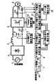
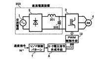
汎用インバータなどで用いられている一般なインダクションモータ駆動用インバータ制御装置として、図20に示すようなV/F制御方式のインダクションモータ駆動用インバータ制御装置がよく知られている(例えば、非特許文献1参照)。 As a general induction motor driving inverter control device used in a general-purpose inverter or the like, a V / F control type induction motor driving inverter control device as shown in FIG. 20 is well known (for example, see Non-Patent Documents). 1).
図20において、主回路は直流電源装置203と、インバータ3とインダクションモータ4とから構成されており、直流電源装置203については、交流電源1と、整流回路2と、インバータ3の直流電圧源のために電気エネルギーを蓄積する平滑コンデンサ202と、交流電源1の力率改善用リアクタ201から構成されている。
20, the main circuit includes a
一方、制御回路では、外部から与えられたインダクションモータ4の速度指令W*に基づいてインダクションモータ4に印加するモータ電圧値を決定するV/F制御パターン7と、V/F制御パターン7から決定されるモータ電圧値に基づいてインダクションモータ4のモータ電圧指令値を作成するモータ電圧作成手段8と、モータ電圧作成手段8から作成されたモータ電圧指令値に基づいてインバータ3のPWM信号を生成するPWM制御手段12から構成されている。
On the other hand, in the control circuit, a V /
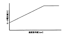
なお、一般的なV/F制御パターン7の一例を図21に示す。図21に示すように速度指令W*に対してインダクションモータ4に印加するモータ電圧値が一義的に決定するような構成となっている。一般的には、速度指令W*とモータ電圧値の値をテーブル値としてマイコン等の演算装置のメモリに記憶させ、テーブル値以外の速度指令W*に対してはテーブル値から線形補間することでモータ電圧値を導出している。
An example of a general V /
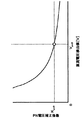
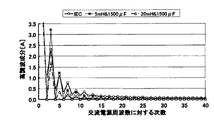
ここで、交流電源1が220V(交流電源周波数50Hz)、インバータ3の入力が1.5kW、平滑コンデンサ202が1500μFのとき、力率改善用リアクタ201が5mHおよび20mHの場合における交流電源電流の高調波成分と交流電源周波数に対する次数との関係を図22に示す。図22はIEC(国際電気標準会議)規格と併せて示したもので、力率改善用リアクタ201が5mHの場合には特に第3高調波成分がIEC規格のそれを大きく上回っているが、20mHの場合には40次までの高調波成分においてIEC規格をクリアしていることがわかる。
Here, when the AC power supply 1 is 220 V (AC power supply frequency 50 Hz), the input of the inverter 3 is 1.5 kW, and the
そのため特に高負荷時においてもIEC規格をクリアするためには力率改善用リアクタ201のインダクタンス値を更に大きくするなどの対策を取る必要があり、インバータ装置の大型化や重量増加、更にはコストUPを招くという不都合があった。
Therefore, it is necessary to take measures such as further increasing the inductance value of the power
そこで、力率改善用リアクタ201のインダクタンス値の増加を抑え、電源高調波成分の低減と高力率化を達成する直流電源装置として、例えば図23に示すような直流電源装置が提案されている(例えば、特許文献1)。
Therefore, as a DC power supply that suppresses an increase in the inductance value of the power
図23において、交流電源1の交流電源電圧を、ダイオードD1〜D4をブリッジ接続してなる全波整流回路の交流入力端子に印加し、その出力をリアクトルLinを介して中間コンデンサCに充電し、この中間コンデンサCの電荷を平滑コンデンサCDに放電して、負荷抵抗RLに直流電圧を供給する。この場合、リアクトルLinの負荷側と中間コンデンサCを接続する正負の直流電流経路にトランジスタQ1を接続し、このトランジスタQ1をベース駆動回路G1で駆動する構成となっている。 In FIG. 23, the AC power supply voltage of the AC power supply 1 is applied to an AC input terminal of a full-wave rectifier circuit in which diodes D1 to D4 are bridge-connected, and the output is charged to the intermediate capacitor C via the reactor Lin. The charge of the intermediate capacitor C is discharged to the smoothing capacitor CD to supply a DC voltage to the load resistor RL. In this case, the transistor Q1 is connected to a positive / negative DC current path connecting the load side of the reactor Lin and the intermediate capacitor C, and the transistor Q1 is driven by the base drive circuit G1.
また、ベース駆動回路G1にパルス電圧を印加するパルス発生回路I1、I2と、ダミー抵抗Rdmとを更に備えており、パルス発生回路I1、I2は、それぞれ交流電源電圧のゼロクロス点を検出する回路と、ゼロクロス点の検出から交流電源電圧の瞬時値が中間コンデンサCの両端電圧と等しくなるまでダミー抵抗Rdmにパルス電流を流すパルス電流回路とで構成されている。 Further, it further includes pulse generation circuits I1 and I2 for applying a pulse voltage to the base drive circuit G1, and a dummy resistor Rdm, wherein each of the pulse generation circuits I1 and I2 detects a zero-cross point of the AC power supply voltage. And a pulse current circuit that supplies a pulse current to the dummy resistor Rdm until the instantaneous value of the AC power supply voltage becomes equal to the voltage across the intermediate capacitor C from the detection of the zero crossing point.
ここで、パルス発生回路I1は交流電源電圧の半サイクルの前半にてパルス電圧を発生させ、パルス発生I2は交流電源電圧の半サイクルの後半にてパルス電圧を発生させるようになっている。 Here, the pulse generation circuit I1 generates a pulse voltage in the first half of a half cycle of the AC power supply voltage, and the pulse generation I2 generates a pulse voltage in the second half of the half cycle of the AC power supply voltage.
なお、トランジスタQ1をオン状態にしてリアクトルLinに強制的に電流を流す場合、中間コンデンサCの電荷がトランジスタQ1を通して放電することのないように逆流防止用ダイオードD5が接続され、更に、中間コンデンサCの電荷を平滑コンデンサCDに放電する経路に、逆流防止用ダイオードD6と、平滑効果を高めるリアクトルLdcが直列に接続されている。 When the transistor Q1 is turned on to force a current to flow through the reactor Lin, a backflow prevention diode D5 is connected so that the charge of the intermediate capacitor C is not discharged through the transistor Q1, and the intermediate capacitor C A diode D6 for preventing backflow and a reactor Ldc for enhancing a smoothing effect are connected in series to a path for discharging the electric charge of the above to the smoothing capacitor CD.
上記の構成によって、交流電源電圧の瞬時値が中間コンデンサCの両端電圧を超えない位相区間の一部または全部においてトランジスタQ1をオン状態にすることによって、装置の大型化を抑えたままで、高調波成分の低減と高力率化を達成することができる。 With the above configuration, the transistor Q1 is turned on in a part or all of the phase section in which the instantaneous value of the AC power supply voltage does not exceed the voltage between both ends of the intermediate capacitor C. It is possible to achieve a reduction in components and a high power factor.
しかしながら、上記従来の構成では、容量の大きな平滑用コンデンサCDとリアクトルLin(特許文献1では1500μF、6.2mH時のシミュレーション結果について記載されている)とを以前として有したままであり、更に中間コンデンサCとトランジスタQ1とベース駆動回路G1とパルス発生回路I1、I2とダミー抵抗Rdmと逆流防止用ダイオードD5、D6と平滑効果を高めるリアクトルLdcとを具備することで、装置の大型化や部品点数の増加に伴なうコストUPを招くという課題を有していた。 However, in the above-mentioned conventional configuration, the smoothing capacitor CD having a large capacity and the reactor Lin (the simulation result at 1500 μF and 6.2 mH is described in Patent Document 1) remain as before, and furthermore the intermediate By including the capacitor C, the transistor Q1, the base drive circuit G1, the pulse generation circuits I1 and I2, the dummy resistor Rdm, the backflow prevention diodes D5 and D6, and the reactor Ldc for enhancing the smoothing effect, the device can be increased in size and the number of parts can be reduced. There is a problem that the cost is increased due to the increase in the cost.
本発明はこのような従来の課題を解決するものであり、モータ電流の変動量を低減することで、更なる小型・軽量・低コスト化を図ったモータ駆動用インバータ制御装置を提供することを目的とする。 The present invention solves such a conventional problem, and provides a motor drive inverter control device that is further reduced in size, weight, and cost by reducing the amount of change in motor current. Aim.
上記課題を解決するために本発明は、交流電源を入力とする整流回路と直流電力から交流電力に変換するインバータを備えたモータ駆動用インバータ制御装置であって、整流回路はダイオードブリッジと、ダイオードブリッジの交流入力側または直流出力側に接続される所定の小容量のリアクタで構成され、インバータの直流母線間には、モータの回生エネルギーを吸収するための所定の小容量のコンデンサを設け、外部から与えられるモータの速度指令値に基づき、モータのモータ電圧指令値を作成するモータ電圧指令作成手段と、インバータの直流電圧値を検出するPN電圧検出手段と、予め設定されたインバータの直流電圧基準値とPN電圧検出手段から得られるインバータの直流電圧検出値との比率を導出するPN電圧補正手段と、モータ電圧指令作成手段から得られるモータ電圧指令値とPN電圧補正手段の出力値であるPN電圧補正係数とを掛け合わせることによりモータ電圧指令値の電圧補正を行ない、モータのモータ電圧指令補正値を作成するモータ電圧指令補正手段と、モータのモータ電流を検出するモータ電流検出手段と、モータ電流検出手段から得られるモータ電流検出値から前記モータ電流の変動量を導出し、モータ電流変動量の逆位相成分を導出するビート量補正手段と、モータ電圧指令補正手段から得られるモータ電圧指令補正値とビート量補正手段の出力値とを掛け合わせることによりモータ電圧指令補正値の電圧補正を行ない、モータへの印加電圧指令値を作成する第2モータ電圧指令補正手段とを備えるものである。 In order to solve the above problems, the present invention is a motor drive inverter control device including a rectifier circuit that receives an AC power supply and an inverter that converts DC power to AC power, wherein the rectifier circuit includes a diode bridge and a diode. The bridge is composed of a predetermined small-capacity reactor connected to the AC input side or DC output side of the bridge, and a predetermined small-capacity capacitor for absorbing the regenerative energy of the motor is provided between the DC buses of the inverter. A motor voltage command generating means for generating a motor voltage command value of the motor based on the motor speed command value given from the motor; a PN voltage detecting means for detecting an inverter DC voltage value; and a preset inverter DC voltage reference. PN voltage correction means for deriving a ratio between the value and a DC voltage detection value of the inverter obtained from the PN voltage detection means; The motor voltage command value is corrected by multiplying the motor voltage command value obtained from the motor voltage command creation means by the PN voltage correction coefficient which is the output value of the PN voltage correction means, and the motor voltage command correction value of the motor is obtained. Motor voltage command correction means for generating the motor current detection means for detecting the motor current of the motor, and the motor current fluctuation value derived from the motor current detection value obtained from the motor current detection means, Beat amount correction means for deriving an antiphase component, and performing voltage correction of the motor voltage command correction value by multiplying a motor voltage command correction value obtained from the motor voltage command correction means and an output value of the beat amount correction means, And a second motor voltage command correcting means for generating a voltage command value to be applied to the motor.
上記の構成によって、小容量リアクタおよび小容量コンデンサを用いることで小型・軽量・低コストなモータ駆動用インバータ制御装置を実現でき、インバータ直流電圧が大幅に変動してモータの駆動が困難あるいは不可能となる場合でも、PN電圧補正手段によりモータに印加する電圧をほぼ一定にすることでモータの駆動を維持することが可能となり、更にビート量補正手段によりモータ電流の変動量を抑制することで損失低減や素子の電流容量低減によるモータ駆動用インバータ制御装置の更なる小型・軽量・低コスト化を図ることが可能である。 With the above configuration, a small-sized, light-weight, and low-cost inverter control device for motor drive can be realized by using a small-capacity reactor and a small-capacity capacitor. In this case, it is possible to maintain the driving of the motor by making the voltage applied to the motor substantially constant by the PN voltage correction means, and further to suppress the loss by suppressing the fluctuation amount of the motor current by the beat amount correction means. It is possible to further reduce the size, weight, and cost of the motor drive inverter control device by reducing the current and the current capacity of the elements.
また、ビート量補正手段は、モータ電流検出値の平均演算によりモータ電流変動量を導出するものである。 The beat amount correction means derives the motor current fluctuation amount by averaging the motor current detection values.
上記の構成によって、簡単な演算によりモータ電流変動量を導出することができるため、マイコン等の演算手段における演算量やメモリの大幅な増加を防ぐことができ、同等コストの演算手段で構成することが可能である。 With the above configuration, the motor current fluctuation amount can be derived by a simple calculation, so that it is possible to prevent a large increase in the calculation amount and the memory in the calculation means such as the microcomputer, and to configure the calculation means with the same cost. Is possible.
また、ビート量補正手段は、インバータの運転周波数の周期毎にモータ電流検出値の平均値を導出し、モータ電流検出値の平均値を導出している期間においては少なくとも1周期前のモータ電流検出値の平均値をモータ電流変動量とし、モータ電流検出値の平均値を導出している期間が終了すればモータ電流変動量を新たに更新するものである。 The beat amount correcting means derives an average value of the motor current detection value for each cycle of the operation frequency of the inverter, and during a period in which the average value of the motor current detection value is derived, determines at least one cycle before the motor current detection value. The average value of the values is defined as the motor current fluctuation amount, and the motor current fluctuation amount is newly updated when the period during which the average value of the motor current detection value is derived ends.
上記の構成によって、インバータの運転周波数の周期毎にモータ電流検出値の平均値を導出しているため、マイコン等の演算手段における演算量やメモリの低減が図れ、演算手段のコスト低減を図ることが可能である。 With the above configuration, the average value of the motor current detection value is derived for each cycle of the operating frequency of the inverter, so that the amount of calculation and memory in the calculation means such as a microcomputer can be reduced, and the cost of the calculation means can be reduced. Is possible.
また、ビート量補正手段は、モータ電流検出値の正負の割合を導出し、正負の割合の平均演算によりモータ電流変動量を導出するものである。 The beat amount correcting means derives a positive / negative ratio of the motor current detection value, and derives a motor current fluctuation amount by averaging the positive / negative ratio.
上記の構成によって、モータ電流検出値をそのまま平均演算するのに対して、マイコン等の演算手段における演算量やメモリの低減を図れ、演算手段のコスト低減を図ることが可能である。 According to the above configuration, the average calculation of the motor current detection value is performed as it is, but the amount of calculation and memory in the calculation means such as a microcomputer can be reduced, and the cost of the calculation means can be reduced.
また、ビート量補正手段は、インバータの運転周波数の周期毎に正負の割合の平均値を導出し、正負の割合の平均値を導出している期間においては少なくとも1周期前の正負の割合の平均値をモータ電流変動量とし、正負の割合の平均値を導出している期間が終了すればモータ電流変動量を新たに更新するものである。 Further, the beat amount correction means derives an average value of the positive / negative ratio for each cycle of the operating frequency of the inverter, and in a period in which the average value of the positive / negative ratio is derived, averages the positive / negative ratio at least one cycle before The value is defined as the motor current variation, and the motor current variation is newly updated when the period during which the average value of the positive and negative ratios is derived ends.
上記の構成によって、インバータの運転周波数の周期毎に正負の割合の平均値を導出しているため、インバータの運転周波数の周期毎にモータ電流検出値の平均値を導出する場合よりも更にマイコン等の演算手段における演算量やメモリの低減が図れ、演算手段のコスト低減を図ることが可能である。 With the above configuration, since the average value of the positive / negative ratio is derived for each cycle of the inverter operating frequency, a microcomputer or the like is further required than when the average value of the motor current detection value is derived for each cycle of the inverter operating frequency. It is possible to reduce the amount of calculation and memory in the calculation means, and to reduce the cost of the calculation means.
また、ビート量補正手段は、モータ電流検出値の1次遅れ演算によりモータ電流変動量を導出するものである。 The beat amount correcting means derives a motor current fluctuation amount by a first-order lag calculation of the motor current detection value.
上記の構成によって、モータ電流検出値を平均演算するのに対して、マイコン等の演算手段における演算量やメモリの低減が図れ、演算手段のコスト低減を図ることが可能である。 According to the above configuration, the amount of calculation and the memory in the calculation means such as a microcomputer can be reduced, while the average calculation of the motor current detection value is performed, and the cost of the calculation means can be reduced.
また、ビート量補正手段は、インバータの運転周波数が1次遅れ演算におけるカットオフ周波数よりも大きい場合のみモータ電流変動量を抑制するものである。 Also, the beat amount correcting means suppresses the motor current fluctuation amount only when the operating frequency of the inverter is higher than the cutoff frequency in the first-order lag calculation.
上記の構成によって、モータのモータ電流がハンチングするような不安定現象を回避することができる。 With the above configuration, an unstable phenomenon such as hunting of the motor current of the motor can be avoided.
また、ビート量補正手段は、1次遅れ演算に伴なう時間遅れを補償する遅延時間補償手段を備えるものである。 Further, the beat amount correcting means includes a delay time compensating means for compensating for a time delay caused by the primary delay calculation.
上記の構成によって、1次遅れ演算に伴なう遅延時間を補償することができるため、モータ電流変動量の抑制効果の向上を図ることが可能である。 With the above-described configuration, the delay time associated with the first-order delay calculation can be compensated, so that the effect of suppressing the motor current variation can be improved.
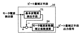
また、ビート量補正手段は、モータ電流検出値からモータ電流の基本波成分を検出する基本波電流検出手段を備え、モータ電流検出値と基本波電流検出手段の出力値との差分によりモータ電流変動量を導出するものである。 Further, the beat amount correcting means includes a fundamental wave current detecting means for detecting a fundamental wave component of the motor current from the detected motor current value, and the motor current fluctuation is determined by a difference between the motor current detected value and an output value of the fundamental wave current detecting means. Deriving the quantity.
上記の構成によって、モータ電流検出値を1次遅れ演算するのに対して、マイコン等の演算手段における演算量やメモリの低減が図れ、演算手段のコスト低減を図ることが可能である。 According to the above-described configuration, the amount of calculation and memory in the calculation means such as a microcomputer can be reduced as compared with the first-order delay calculation of the motor current detection value, and the cost of the calculation means can be reduced.
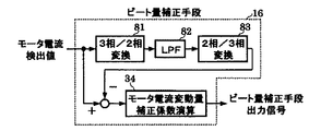
また、基本波電流検出手段は、モータ電流検出値を3相/2相変換したものを1次遅れ演算し、更に2相/3相変換することでモータ電流基本波成分を導出するものである。 In addition, the fundamental wave current detection means derives a motor current fundamental wave component by performing a first-order lag operation on a three-phase / two-phase conversion of the motor current detection value and further performing a two-phase / three-phase conversion. .
上記の構成によって、モータ電流検出値を3相交流から2相直流に変換した後で1次遅れ演算するため、リアルタイムにて時間遅れなくモータ電流変動量を導出することによりモータ電流変動量の抑制効果の向上を図ることが可能である。 According to the above configuration, since the motor current detection value is converted from three-phase AC to two-phase DC and then the first-order lag calculation is performed, the motor current fluctuation is derived without time delay in real time, thereby suppressing the motor current fluctuation. The effect can be improved.
また、モータ電流変動量が予め設定されたモータ電流変動量の設定値よりも大きい場合のみモータ電流変動量の抑制をするものである。 Further, the motor current fluctuation amount is suppressed only when the motor current fluctuation amount is larger than a preset value of the motor current fluctuation amount.
上記の構成によって、モータ電流変動量が予め設定されたモータ電流変動量の設定値よりも大きい場合のみモータ電流変動量の抑制をすることで効果的にモータ電流変動量の抑制をすることができ、更にマイコン等の演算手段における演算量やメモリの低減が図れ、演算手段のコスト低減を図ることが可能である。 According to the above configuration, the motor current fluctuation can be effectively suppressed by suppressing the motor current fluctuation only when the motor current fluctuation is larger than a preset value of the motor current fluctuation. Furthermore, the amount of calculation and memory in the calculation means such as a microcomputer can be reduced, and the cost of the calculation means can be reduced.
また、インバータの運転周波数が予め設定されたインバータ運転周波数設定値よりも大きい場合のみモータ電流変動量の抑制をするものである。 Further, the motor current fluctuation amount is suppressed only when the operation frequency of the inverter is higher than a preset inverter operation frequency set value.
上記の構成によって、インバータの運転周波数が予め設定されたインバータ運転周波数設定値よりも大きい場合のみモータ電流変動量の抑制をすることで効果的にモータ電流変動量の抑制をすることができ、更にマイコン等の演算手段における演算量やメモリの低減が図れ、演算手段のコスト低減を図ることが可能である。 According to the above configuration, the motor current variation can be effectively suppressed by suppressing the motor current variation only when the operating frequency of the inverter is higher than a preset inverter operating frequency set value. It is possible to reduce the amount of calculation and memory in the calculation means such as a microcomputer, and it is possible to reduce the cost of the calculation means.
また、モータが加速あるいは減速するような過渡状態においては前記モータ電流変動量の抑制をしないものである。 In a transient state in which the motor accelerates or decelerates, the motor current fluctuation amount is not suppressed.
上記の構成によって、モータが加速あるいは減速するような過渡状態でのモータ電流変動量の抑制をしないことでモータのモータ電流がハンチングするような不安定現象を回避することができ、更にマイコン等の演算手段における演算量やメモリの低減が図れ、演算手段のコスト低減を図ることが可能である。 With the above configuration, it is possible to avoid an unstable phenomenon such as hunting of the motor current of the motor by not suppressing a motor current fluctuation amount in a transient state where the motor accelerates or decelerates. It is possible to reduce the amount of calculation and memory in the calculating means, and it is possible to reduce the cost of the calculating means.
また、モータ電流検出手段は、インバータの母線電流に流れる電流を検出する電流検出器を備えるものであり、インバータの過電流保護のためにインバータの直流母線に予め設けられているシャント抵抗を電流検出器として兼用し、電流検出器の出力値からキャリア周波数に同期してモータ電流を検出するものである。 Further, the motor current detecting means includes a current detector for detecting a current flowing in the bus current of the inverter, and detects a shunt resistance provided in advance on the DC bus of the inverter for overcurrent protection of the inverter. A motor current is detected in synchronization with the carrier frequency from the output value of the current detector.
上記の構成によって、電流センサを用いる場合に比べて、モータ電流検出手段にかかるコストを必要最小限とすることが可能である。 With the above configuration, it is possible to minimize the cost required for the motor current detection unit as compared with the case where a current sensor is used.
上記から明らかなように、本発明は、交流電源を入力とする整流回路と直流電力から交流電力に変換するインバータとモータとを含み、整流回路はダイオードブリッジと、ダイオードブリッジの交流入力側または直流出力側に接続される所定の小容量のリアクタで構成され、インバータの直流母線間には、モータの回生エネルギーを吸収するための所定の小容量のコンデンサを設け、外部から与えられるモータの速度指令値に基づき、モータのモータ電圧指令値を作成するモータ電圧指令作成手段と、インバータの直流電圧値を検出するPN電圧検出手段と、予め設定されたインバータの直流電圧基準値とPN電圧検出手段から得られるインバータの直流電圧検出値との比率を導出するPN電圧補正手段と、モータ電圧指令作成手段から得られるモータ電圧指令値とPN電圧補正手段の出力値であるPN電圧補正係数とを掛け合わせることによりモータ電圧指令値の電圧補正を行ない、モータのモータ電圧指令補正値を作成するモータ電圧指令補正手段と、モータのモータ電流を検出するモータ電流検出手段と、モータ電流検出手段から得られるモータ電流検出値から前記モータ電流の変動量を導出し、モータ電流変動量の逆位相成分を導出するビート量補正手段と、モータ電圧指令補正手段から得られるモータ電圧指令補正値とビート量補正手段の出力値とを掛け合わせることによりモータ電圧指令補正値の電圧補正を行ない、モータへの印加電圧指令値を作成する第2モータ電圧指令補正手段とを備えるもので、この構成によれば、小容量リアクタおよび小容量コンデンサを用いることで小型・軽量・低コストなモータ駆動用インバータ制御装置を実現でき、インバータ直流電圧が大幅に変動してモータの駆動が困難あるいは不可能となる場合でも、PN電圧補正手段によりモータに印加する電圧をほぼ一定にすることでモータの駆動を維持することが可能となり、更にビート量補正手段によりモータ電流の変動量を抑制することで損失低減や素子の電流容量低減によるモータ駆動用インバータ制御装置の更なる小型・軽量・低コスト化を図ることが可能であるという効果を奏する。 As is clear from the above, the present invention includes a rectifier circuit having an AC power supply as an input, an inverter for converting DC power to AC power, and a motor, the rectifier circuit includes a diode bridge, and an AC input side or DC of the diode bridge. It is composed of a predetermined small-capacity reactor connected to the output side, and a predetermined small-capacity capacitor for absorbing the regenerative energy of the motor is provided between the DC bus of the inverter. A motor voltage command generating means for generating a motor voltage command value of the motor based on the value; a PN voltage detecting means for detecting a DC voltage value of the inverter; and a preset inverter DC voltage reference value and PN voltage detecting means. PN voltage correction means for deriving the ratio between the obtained inverter DC voltage value and motor voltage command generation means. Motor voltage command correction means for performing a voltage correction of the motor voltage command value by multiplying a motor voltage command value to be multiplied by a PN voltage correction coefficient which is an output value of the PN voltage correction means, thereby creating a motor voltage command correction value for the motor. And a motor current detecting means for detecting a motor current of the motor; and a beat amount for deriving an amount of fluctuation of the motor current from a motor current detection value obtained from the motor current detecting means, and deriving an antiphase component of the motor current fluctuation amount. The correction means and the motor voltage command correction value obtained from the motor voltage command correction means are multiplied by the output value of the beat amount correction means to perform the voltage correction of the motor voltage command correction value, and the applied voltage command value to the motor is corrected. And a second motor voltage command correcting means to be created. According to this configuration, a small capacity reactor and a small capacity capacitor are used. This makes it possible to realize a compact, lightweight, and low-cost inverter controller for driving a motor. Even when the DC voltage of the inverter fluctuates greatly and driving of the motor becomes difficult or impossible, the PN voltage correction means applies the voltage to the motor. The motor drive can be maintained by making the applied voltage almost constant, and furthermore, the amount of fluctuation of the motor current is suppressed by the beat amount correction means, thereby reducing the loss and the motor drive inverter control by reducing the element current capacity. There is an effect that the size, weight and cost of the device can be further reduced.
また、本発明は、ビート量補正手段は、モータ電流検出値の平均演算によりモータ電流変動量を導出するもので、この構成によれば、簡単な演算によりモータ電流変動量を導出することができるため、マイコン等の演算手段における演算量やメモリの大幅な増加を防ぐことができ、同等コストの演算手段で構成することが可能であるという効果を奏する。 Further, according to the present invention, the beat amount correcting means derives the motor current fluctuation amount by averaging the motor current detection value. According to this configuration, the motor current fluctuation amount can be derived by a simple calculation. Therefore, it is possible to prevent a large increase in the amount of calculation and the memory in the calculation means such as a microcomputer, and it is possible to achieve the effect that the calculation means can be configured with the same cost.
また、本発明は、ビート量補正手段は、インバータの運転周波数の周期毎にモータ電流検出値の平均値を導出し、モータ電流検出値の平均値を導出している期間においては少なくとも1周期前のモータ電流検出値の平均値をモータ電流変動量とし、モータ電流検出値の平均値を導出している期間が終了すればモータ電流変動量を新たに更新するもので、この構成によれば、インバータの運転周波数の周期毎にモータ電流検出値の平均値を導出しているため、マイコン等の演算手段における演算量やメモリの低減が図れ、演算手段のコスト低減を図ることが可能であるという効果を奏する。 Also, in the present invention, the beat amount correction means derives an average value of the motor current detection value for each cycle of the operating frequency of the inverter, and at least one cycle before the average value of the motor current detection value is derived. The average value of the motor current detection values is used as the motor current fluctuation amount, and the motor current fluctuation amount is newly updated when the period in which the average value of the motor current detection values is derived ends. According to this configuration, Since the average value of the motor current detection value is derived for each cycle of the operating frequency of the inverter, it is possible to reduce the amount of calculation and memory in the calculation means such as a microcomputer, and to reduce the cost of the calculation means. It works.
また、本発明は、ビート量補正手段は、モータ電流検出値の正負の割合を導出し、正負の割合の平均演算によりモータ電流変動量を導出するもので、この構成によれば、モータ電流検出値をそのまま平均演算するのに対して、マイコン等の演算手段における演算量やメモリの低減を図れ、演算手段のコスト低減を図ることが可能であるという効果を奏する。 Further, according to the present invention, the beat amount correcting means derives a positive / negative ratio of the motor current detection value, and derives a motor current fluctuation amount by averaging the positive / negative ratio. Compared to averaging the values as they are, it is possible to reduce the amount of calculation and the memory in the calculation means such as a microcomputer, and to reduce the cost of the calculation means.
また、本発明は、ビート量補正手段は、インバータの運転周波数の周期毎に正負の割合の平均値を導出し、正負の割合の平均値を導出している期間においては少なくとも1周期前の正負の割合の平均値をモータ電流変動量とし、正負の割合の平均値を導出している期間が終了すればモータ電流変動量を新たに更新するもので、この構成によれば、インバータの運転周波数の周期毎に正負の割合の平均値を導出しているため、インバータの運転周波数の周期毎にモータ電流検出値の平均値を導出する場合よりも更にマイコン等の演算手段における演算量やメモリの低減が図れ、演算手段のコスト低減を図ることが可能であるという効果を奏する。 Also, in the present invention, the beat amount correction means derives an average value of the positive / negative ratio for each cycle of the operating frequency of the inverter, and in a period in which the average value of the positive / negative ratio is derived, at least one cycle before the positive / negative value. The average value of the ratio of the motor current fluctuation is defined as the motor current fluctuation amount, and the motor current fluctuation amount is updated anew when the period of deriving the average value of the positive and negative ratios ends. The average value of the positive / negative ratio is derived for each cycle of the inverter. This has the effect of reducing the cost of the calculation means.
また、本発明は、ビート量補正手段は、モータ電流検出値の1次遅れ演算によりモータ電流変動量を導出するもので、この構成によれば、モータ電流検出値を平均演算するのに対して、マイコン等の演算手段における演算量やメモリの低減が図れ、演算手段のコスト低減を図ることが可能であるという効果を奏する。 Further, according to the present invention, the beat amount correcting means derives the motor current fluctuation amount by a first-order lag calculation of the motor current detection value. In addition, it is possible to reduce the amount of calculation and the memory in the calculation means such as a microcomputer, and to reduce the cost of the calculation means.
また、本発明は、ビート量補正手段は、インバータの運転周波数が1次遅れ演算におけるカットオフ周波数よりも大きい場合のみモータ電流変動量を抑制するもので、この構成によれば、モータのモータ電流がハンチングするような不安定現象を回避することができるという効果を奏する。 Further, according to the present invention, the beat amount correcting means suppresses the motor current fluctuation amount only when the operating frequency of the inverter is higher than the cutoff frequency in the first-order lag calculation. This has an effect that an unstable phenomenon such as hunting can be avoided.
また、本発明は、ビート量補正手段は、1次遅れ演算に伴なう時間遅れを補償する遅延時間補償手段を備えるもので、この構成によれば、1次遅れ演算に伴なう遅延時間を補償することができるため、モータ電流変動量の抑制効果の向上を図ることが可能であるという効果を奏する。 Further, according to the present invention, the beat amount correcting means includes a delay time compensating means for compensating for a time delay accompanying the first-order delay calculation. Therefore, the effect of suppressing the motor current fluctuation can be improved.
また、本発明は、ビート量補正手段は、モータ電流検出値からモータ電流の基本波成分を検出する基本波電流検出手段を備え、モータ電流検出値と基本波電流検出手段の出力値との差分によりモータ電流変動量を導出するもので、この構成によれば、モータ電流検出値を1次遅れ演算するのに対して、マイコン等の演算手段における演算量やメモリの低減が図れ、演算手段のコスト低減を図ることが可能であるという効果を奏する。 Further, in the present invention, the beat amount correcting means includes a fundamental wave current detecting means for detecting a fundamental wave component of the motor current from the motor current detected value, and a difference between the motor current detected value and an output value of the fundamental wave current detecting means. According to this configuration, the first-order lag calculation of the motor current detection value is performed, but the amount of calculation and the memory in the calculation means such as a microcomputer can be reduced. This has the effect of enabling cost reduction.
また、本発明は、基本波電流検出手段は、モータ電流検出値を3相/2相変換したものを1次遅れ演算し、更に2相/3相変換することでモータ電流基本波成分を導出するもので、この構成によって、モータ電流検出値を3相交流から2相直流に変換した後で1次遅れ演算するため、リアルタイムにて時間遅れなくモータ電流変動量を導出することによりモータ電流変動量の抑制効果の向上を図ることが可能であるという効果を奏する。 Further, in the present invention, the fundamental wave current detecting means performs a first-order lag operation on a three-phase / two-phase conversion of the motor current detection value, and further derives a motor current fundamental wave component by performing a two-phase / 3-phase conversion. According to this configuration, since the motor current detection value is converted from three-phase AC to two-phase DC and then the first-order lag operation is performed, the motor current fluctuation is derived in real time without time delay. This has the effect that the effect of suppressing the amount can be improved.
また、本発明は、モータ電流変動量が予め設定されたモータ電流変動量の設定値よりも大きい場合のみモータ電流変動量の抑制をするもので、この構成によれば、モータ電流変動量が予め設定されたモータ電流変動量の設定値よりも大きい場合のみモータ電流変動量の抑制をすることで効果的にモータ電流変動量の抑制をすることができ、更にマイコン等の演算手段における演算量やメモリの低減が図れ、演算手段のコスト低減を図ることが可能であるという効果を奏する。 Further, the present invention suppresses the motor current fluctuation amount only when the motor current fluctuation amount is larger than a preset value of the motor current fluctuation amount. According to this configuration, the motor current fluctuation amount is set in advance. The motor current variation can be effectively suppressed by suppressing the motor current variation only when the motor current variation is greater than the set value of the set motor current variation. The memory can be reduced, and the cost of the calculation means can be reduced.
また、本発明は、インバータの運転周波数が予め設定されたインバータ運転周波数設定値よりも大きい場合のみモータ電流変動量の抑制をするもので、この構成によれば、インバータの運転周波数が予め設定されたインバータ運転周波数設定値よりも大きい場合のみモータ電流変動量の抑制をすることで効果的にモータ電流変動量の抑制をすることができ、更にマイコン等の演算手段における演算量やメモリの低減が図れ、演算手段のコスト低減を図ることが可能であるという効果を奏する。 Further, the present invention suppresses the motor current fluctuation amount only when the operating frequency of the inverter is higher than a preset inverter operating frequency set value. According to this configuration, the operating frequency of the inverter is set in advance. By suppressing the motor current fluctuation only when it is larger than the inverter operation frequency set value, the motor current fluctuation can be effectively suppressed. Thus, there is an effect that the cost of the calculation means can be reduced.
また、本発明は、モータが加速あるいは減速するような過渡状態においては前記モータ電流変動量の抑制をしないもので、この構成によれば、モータが加速あるいは減速するような過渡状態でのモータ電流変動量の抑制をしないことでモータのモータ電流がハンチングするような不安定現象を回避することができ、更にマイコン等の演算手段における演算量やメモリの低減が図れ、演算手段のコスト低減を図ることが可能であるという効果を奏する。 Further, the present invention does not suppress the motor current fluctuation amount in a transient state in which the motor accelerates or decelerates. According to this configuration, the motor current in the transient state in which the motor accelerates or decelerates By not suppressing the fluctuation amount, an unstable phenomenon such as hunting of the motor current of the motor can be avoided, and furthermore, the calculation amount and memory in the calculation means such as a microcomputer can be reduced, and the cost of the calculation means can be reduced. This has the effect that it is possible.
また、モータ電流検出手段は、インバータの母線電流に流れる電流を検出する電流検出器を備えるものであり、インバータの過電流保護のためにインバータの直流母線に予め設けられているシャント抵抗を電流検出器として兼用し、電流検出器の出力値からキャリア周波数に同期してモータ電流を検出するものであり、この構成によれば、電流センサを用いる場合に比べて、モータ電流検出手段にかかるコストを必要最小限とすることが可能であるという効果を奏する。 Further, the motor current detecting means includes a current detector for detecting a current flowing in the bus current of the inverter, and detects a shunt resistance provided in advance on the DC bus of the inverter for overcurrent protection of the inverter. The motor current is detected in synchronization with the carrier frequency from the output value of the current detector. According to this configuration, the cost for the motor current detection means is reduced as compared with the case where the current sensor is used. There is an effect that it can be minimized.
以下本発明の実施の形態について図面を参照しながら説明する。なお、以下に述べる実施の形態ではインダクションモータ駆動用インバータ制御装置について説明しているが、本発明はインダクションモータ駆動用インバータ制御装置に限ることなく、全てのモータ駆動用インバータ制御装置に適用できるものである。 Hereinafter, embodiments of the present invention will be described with reference to the drawings. In the embodiments described below, an inverter control device for driving an induction motor is described. However, the present invention is not limited to the inverter control device for driving an induction motor, and can be applied to all inverter control devices for driving a motor. It is.
(実施の形態1)
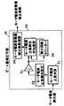
本発明の第1の実施形態を示すインダクションモータ駆動用インバータ制御装置のシステム構成図を図1に示す。図1において、主回路は交流電源1と、交流電力を直流電力に変換するダイオードブリッジ2と、小容量リアクタ5と、小容量コンデンサ6と、直流電力を交流電力に変換するインバータ3と、インバータ3により変換された交流電力により駆動するインダクションモータ4から構成されている。
(Embodiment 1)
FIG. 1 shows a system configuration diagram of an inverter control device for driving an induction motor according to a first embodiment of the present invention. In FIG. 1, the main circuit includes an AC power supply 1, a
一方、制御回路では、外部から与えられた速度指令W*に基づいてインダクションモータ4に印加するモータ電圧値を決定するV/F制御パターン7と、V/F制御パターン7から決定されるモータ電圧値に基づいてインダクションモータ4のモータ電圧指令値を作成するモータ電圧作成手段8と、インバータ3の直流電圧値を検出するPN電圧検出手段9と、予め設定されたインバータ3の直流電圧基準値とPN電圧検出手段9から得られるインバータ3の直流電圧検出値との比率を導出するPN電圧補正手段10と、モータ電圧指令作成手段8から得られるモータ電圧指令値とPN電圧補正手段10の出力値であるPN電圧補正係数とを掛け合わせることによりモータ電圧指令値の電圧補正を行ないインダクションモータ4のモータ電圧指令補正値を作成するモータ電圧指令補正手段11と、インバータ母線電流検出器13もしくはモータ電流検出器14a、14bによりモータ電流を検出するモータ電流検出手段15と、モータ電流検出手段15から得られるモータ電流検出値からモータ電流の変動量を検出し、モータ電流変動量の逆位相成分を導出するビート量補正手段16と、モータ電圧指令補正手段11から得られるモータ電圧指令補正値とビート量補正手段16の出力値とを掛け合わせることによりモータ電圧指令補正値の電圧補正を行ない、インダクションモータ4への印加電圧指令値を作成する第2モータ電圧指令補正手段17と、第2モータ電圧指令補正手段17から作成された印加電圧指令値に基づいてインバータ3のPWM信号を生成するPWM制御手段12とから構成されている。
On the other hand, in the control circuit, a V /
なお、V/F制御パターン7については、上述の従来の技術で説明しているためここでは説明を省略する(図20の一般的なインダクションモータ駆動用インバータ制御装置)。
Since the V /
以下、具体的な方法について説明する。 Hereinafter, a specific method will be described.
モータ電圧指令作成手段では数(1)で表される演算によりモータ電圧指令値vj *(j=u,v,w)を作成する(以下、同様にj=u,v,wとする)。 The motor voltage command creating means creates a motor voltage command value v j * (j = u, v, w) by an operation represented by Expression (1) (hereinafter, similarly, j = u, v, w). .

また、図2は本発明に係るPN電圧補正手段10の第1の実施形態を示した図で、PN電圧補正手段10では予め設定されたインバータ3の直流電圧基準値Vpn0とPN電圧検出手段10から得られるインバータ3の直流電圧検出値vpnを用いて数(3)のようにPN電圧補正係数kpnを導出する。
FIG. 2 is a diagram showing a first embodiment of the PN voltage correcting means 10 according to the present invention. The PN
なお、数(3)の微小項δ0の代わりに、直流電圧検出値vpnがゼロ以下の場合においてPN電圧補正係数kpnに予め設定されたPN電圧補正係数の最大値を設定することでゼロ割防止を図ることができる。 It should be noted that, in place of the minute term δ 0 of the equation (3), when the DC voltage detection value v pn is equal to or less than zero, the PN voltage correction coefficient k pn is set to the preset maximum value of the PN voltage correction coefficient. It is possible to prevent zero percent discount.
即ち、数(4)のようにPN電圧補正係数kpnを導出しても良い。 That is, the PN voltage correction coefficient k pn may be derived as in equation (4).
なお、PN電圧補正手段10は、PN電圧補正係数kpnが少なくとも予め設定された上限値もしくは下限値を有することで、インバータ直流電圧が大幅に変動するような場合でもインダクションモータの駆動を維持することが可能であり、更に予め設定された上限値もしくは下限値を有することで交流電源電流の変動を抑制し、交流電源力率の改善と交流電源電流の高調波成分を抑制することが可能となる。 Note that the PN voltage correction means 10 maintains the drive of the induction motor even when the inverter DC voltage fluctuates greatly, since the PN voltage correction coefficient kpn has at least a preset upper limit value or lower limit value. It is possible to further suppress the fluctuation of the AC power supply current by having a preset upper limit or lower limit, to improve the AC power supply power factor and to suppress the harmonic component of the AC power supply current. Become.
なお、PN電圧補正手段10は、直流電圧検出値が直流電圧基準値よりも大きい場合には直流電圧検出値に比例してPN電圧補正係数kpnを大きくすることで、インバータ直流電圧が大幅に変動するような場合でもインダクションモータの駆動を維持することが可能であり、更ににインバータ直流電圧が直流電圧基準値よりも大きい場合にPN電圧補正係数を大きくすることでインダクションモータの出力トルクの向上を図ることが可能となる。 When the DC voltage detection value is larger than the DC voltage reference value, the PN voltage correction means 10 increases the PN voltage correction coefficient k pn in proportion to the DC voltage detection value, so that the inverter DC voltage is greatly reduced. Even if it fluctuates, it is possible to maintain the driving of the induction motor, and when the inverter DC voltage is larger than the DC voltage reference value, the output torque of the induction motor is improved by increasing the PN voltage correction coefficient. Can be achieved.
また、モータ電圧指令補正手段11ではモータ電圧指令値vj *とPN電圧補正係数kpnを用いて数(5)のようにモータ電圧指令補正値vjh *を導出する。 Further, the motor voltage command correction means 11 derives the motor voltage command correction value v jh * as shown in Expression (5) using the motor voltage command value v j * and the PN voltage correction coefficient k pn .
なお、このときの諸元としては、交流電源1は220V(交流電源周波数は50Hz)、小容量リアクタ5のインダクタンス値は0.5mH、小容量コンデンサ6の容量は10μF、インバータ運転周波数は90Hzである。
At this time, the specifications of the AC power supply 1 were 220 V (AC power supply frequency was 50 Hz), the inductance value of the
そこで、以下のような方法でモータ電流の変動量を抑制する。 Therefore, the fluctuation amount of the motor current is suppressed by the following method.
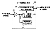
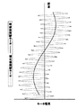
図3は本発明に係るビート量補正手段16の第1の実施形態を示した図で、モータ電流検出値ijを積分器31により積分する際に積分回数カウンター33にてモータ電流検出値ijの1周期における積分回数Nを記憶しておき、モータ電流平均演算部32では積分器31の出力値(モータ電流積分値)を積分回数カウンター33で記憶した積分回数Nで除算することでモータ電流平均値ij_meanを導出する。
FIG. 3 is a diagram showing a first embodiment of the beat amount correction means 16 according to the present invention. When the motor current detection value ij is integrated by the
ここで、図19においてモータ電流検出値ijは、数(6)のように概ね基本波成分i1jと変動量△ijとの合成とすることができるため、モータ電流検出値ijの平均演算によりモータ電流変動量△ijを導出できることがわかる。(正弦波あるいは余弦波を平均演算すればゼロとなるため、明白である) Here, the motor current detection value i j in FIG. 19, the number for generally as (6) may be the combination of the fundamental wave component i 1j and variation △ i j, of the motor current detection value i j It is understood that the motor current fluctuation amount △ ij can be derived by the average calculation. (It is obvious because averaging the sine wave or cosine wave results in zero.)
よって、モータ電流平均値ij_meanは数(8)のように表される。 Thus, the motor current average value i j _ mean is expressed as Expression (8).
また、モータ電流変動量補正係数演算部34ではモータ電流平均値ij_meanの逆位相成分を導出することで各相のビート量補正係数kbjを数(9)の演算により導出する。 Also derived by calculation of the number (9) the phases of the beat amount correction coefficient k bj by deriving the inverse phase component of the motor current average value in the motor current variation amount correction coefficient calculating unit 34 i j _ mean.
また、図9に図3のビート量補正手段におけるモータ電流検出値ijとモータ電流変動量△ijとの関係を示す。モータ電流検出値ijに対して数(8)の演算によりモータ電流平均値ij_meanを導出することでモータ電流変動量△ijが導出されているのがわかる。 The relation between the motor current detection value i j and the motor current variation amount △ i j in the beat amount correction means 3 in FIG. Motor current fluctuation amount by deriving a motor current average value i j _ mean the operation of the equation (8) with respect to the motor current detection value i j △ i j is found that has been derived.
以上により、簡単な演算によりモータ電流変動量を導出することができるため、マイコン等の演算手段における演算量やメモリの大幅な増加を防ぐことができ、同等コストの演算手段で構成することが可能である。 As described above, since the motor current fluctuation amount can be derived by a simple calculation, it is possible to prevent a large increase in the calculation amount and the memory in the calculation means such as the microcomputer, and it is possible to configure the calculation means with the same cost. It is.
次に、第2モータ電圧指令補正手段17では、モータ電圧指令補正値vjh *およびビート量補正係数kbjを用いて数(10)のように印加電圧指令値vjh2 *を導出する。 Next, the second motor voltage command correction means 17 uses the motor voltage command correction value v jh * and the beat amount correction coefficient k bj to derive the applied voltage command value v jh2 * as shown in Expression (10).
なお、本発明のインダクションモータ駆動用インバータ制御装置では、小容量リアクタと小容量コンデンサとの共振周波数を交流電源周波数の40倍よりも大きくなるように小容量リアクタおよび小容量コンデンサの組み合わせを決定することで、交流電源電流の高調波成分を抑制し、IEC規格をクリアすることが可能である。 In the inverter control device for driving an induction motor of the present invention, the combination of the small-capacity reactor and the small-capacity capacitor is determined so that the resonance frequency of the small-capacity reactor and the small-capacity capacitor is larger than 40 times the AC power supply frequency. This makes it possible to suppress the harmonic component of the AC power supply current and clear the IEC standard.
なお、本発明のインダクションモータ駆動用インバータ制御装置では、インバータが停止した際に上昇する直流電圧値の最大値が素子の耐圧よりも小さくなるように小容量コンデンサの容量を決定することで、周辺回路の破壊を防止することが可能となる。 In the inverter control device for driving an induction motor according to the present invention, the capacitance of the small-capacity capacitor is determined such that the maximum value of the DC voltage value that rises when the inverter stops is smaller than the withstand voltage of the element. Circuit destruction can be prevented.
なお、本発明のインダクションモータ駆動用インバータ制御装置では、予め設定された交流電源力率値を満足するようにインバータのキャリア周波数を決定することで、小容量リアクタのキャリア周波数依存性を活用して必要最小限のキャリア周波数を設定することにより、インバータ損失を必要最小限に抑制することが可能となる。 In the inverter control device for driving an induction motor according to the present invention, the carrier frequency of the inverter is determined so as to satisfy a preset AC power factor, thereby utilizing the carrier frequency dependency of the small-capacity reactor. By setting the required minimum carrier frequency, it is possible to suppress inverter loss to the required minimum.
以上のように、本実施形態のインバータ制御装置は、PN電圧補正係数を用いて各相電圧指令値の補正を行なうため、PN電圧の変動があってもほぼ一定のモータ電圧が印加されるようになり、大容量のコンデンサが不要となり、小容量のコンデンサの使用が可能となる。そして、小容量のコンデンサを使用することにより、入力電流は常にモータへ供給されることになり、入力電流の力率が向上するため、リアクタの小型化が実現できる。そして、小容量リアクタおよび小容量コンデンサを用いることで、小型・軽量・低コストのインダクションモータ駆動用インバータ制御装置を実現でき、インバータ直流電圧が大幅に変動してインダクションモータの駆動が困難あるいは不可能となる場合でも、インダクションモータに印加する電圧がほぼ一定となるようにインバータを動作させ、インダクションモータの駆動を維持することが可能となる。更に、ビート量補正手段によりモータ電流の変動量を抑制することで損失低減や素子の電流容量低減によるインダクションモータ駆動用インバータ制御装置の更なる小型・軽量・低コスト化を図ることが可能である。 As described above, the inverter control device of the present embodiment corrects each phase voltage command value using the PN voltage correction coefficient, so that a substantially constant motor voltage is applied even if the PN voltage fluctuates. Therefore, a large-capacity capacitor is not required, and a small-capacity capacitor can be used. By using a small-capacity capacitor, the input current is always supplied to the motor, and the power factor of the input current is improved, so that the reactor can be downsized. By using a small-capacity reactor and a small-capacity capacitor, a compact, lightweight, and low-cost inverter controller for driving an induction motor can be realized, and the inverter DC voltage fluctuates greatly, making it difficult or impossible to drive the induction motor. In this case, the inverter is operated so that the voltage applied to the induction motor is substantially constant, and the drive of the induction motor can be maintained. Further, by suppressing the fluctuation amount of the motor current by the beat amount correcting means, it is possible to further reduce the size, weight and cost of the inverter control device for driving the induction motor by reducing the loss and the current capacity of the element. .
なお、本発明は上述の実施例のようにV/F制御によるインダクションモータ駆動用インバータ制御装置に限定されるものではなく、周知のベクトル制御によるインダクションモータ駆動用インバータ制御装置においても本発明は適用可能である。 It should be noted that the present invention is not limited to the inverter control device for driving an induction motor by V / F control as in the above-described embodiment, and the present invention is also applicable to a known inverter control device for driving a motor by vector control. It is possible.
なお、空気調和機における圧縮機駆動モータなどのようにパルスジェネレータ等の速度センサを使用することができない場合や、サーボドライブなどのように速度センサを具備することができる場合のどちらにおいても本発明は適用可能である。 Note that the present invention is applicable to both cases where a speed sensor such as a pulse generator cannot be used as in a compressor drive motor of an air conditioner and a case where a speed sensor such as a servo drive can be provided. Is applicable.
(実施の形態2)
本発明に係るビート量補正手段の第2の実施形態を図4に示す。図3のビート量補正手段と同じ構成要素は同一符号で示してあり、その説明は重複するので省略し、ここでは異なる部分についてのみ述べる。
(Embodiment 2)
FIG. 4 shows a second embodiment of the beat amount correcting means according to the present invention. The same components as those of the beat amount correction means in FIG. 3 are denoted by the same reference numerals, and the description thereof will be omitted because they are duplicated, and only different portions will be described here.
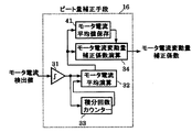
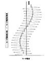
図4において、モータ電流平均演算部32はインバータ運転周波数f1の周期毎にモータ電流平均値ij_meanを導出し、モータ電流平均値保存部41はモータ電流平均演算部32で導出したモータ電流平均値ij_meanのM周期前の値までを保存するものであり、モータ電流平均値ij_meanを導出している期間においては少なくとも1周期前(1〜M周期前)のモータ電流平均値ij_meanをモータ電流変動量△ijとし、モータ電流平均値ij_meanを導出している期間が終了すればモータ電流変動量△ijを新たに更新するものである。
4, the motor current
なお、モータ電流平均値保存部41における保存するモータ電流平均値ij_meanの個数M(M周期前の値までを保存)に関しては、遅延時間や応答性を考慮してインバータ運転周波数f1や負荷条件に応じて予め設定しておく。 Regarding the number of the motor current average value i j _ mean to store in the motor current average value storage unit 41 M (save up to M cycles previous value), the inverter operation frequency f 1 in view of the delay time and responsiveness Or according to load conditions.
また、図10に図4のビート量補正手段におけるモータ電流検出値ijとモータ電流変動量△ijとの関係を示す。図10において○印が演算により導出したモータ電流平均値ij_meanであり、モータ電流平均値ij_meanを導出している期間には1周期前のモータ電流平均値ij_meanをモータ電流変動量△ijとし、モータ電流検出値ij_meanを導出している期間が終了すればモータ電流変動量△ijを新たに更新するものである。 The relation between the motor current detection value i j and the motor current variation amount △ i j in the beat amount correction means 4 in FIG. 10. A motor current average value i j _ mean that ○ mark is derived by calculation in FIG. 10, the motor current average value i j _ mean one cycle before the time period that derives the motor current average value i j _ mean motor current fluctuation amount △ and i j, in which period that derives the motor current detection value i j _ mean is newly updated motor current fluctuation amount △ i j if finished.
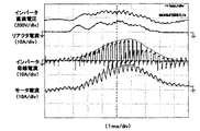
ここで、本発明のインダクションモータ駆動用インバータ制御装置を動作させた場合の結果を図15および図16に示す。図15はモータ電流変動量△ijの抑制をしない場合の動作結果で、図16はモータ電流変動量△ijの抑制をする場合(モータ電流平均値ij_meanを導出している期間においては1周期前のモータ電流平均値ij_meanをモータ電流変動量△ijとしている)の動作結果であり、図15に対して図16のモータ電流ではモータ電流変動量△ijが低減されていることがわかる。
Here, FIGS. 15 and 16 show the results when the inverter control device for driving an induction motor of the present invention was operated. Figure 15 is a operation result when no inhibition of motor current fluctuation amount △ i j,
なお、このときの諸元としては、交流電源は220V(交流電源周波数は50Hz)、小容量リアクタのインダクタンス値は0.5mH、小容量コンデンサの容量は10μF、インバータ運転周波数は96Hzである。 At this time, the specifications of the AC power supply were 220 V (AC power supply frequency was 50 Hz), the inductance value of the small capacity reactor was 0.5 mH, the capacity of the small capacity capacitor was 10 μF, and the inverter operating frequency was 96 Hz.
以上により、インバータの運転周波数の周期毎にモータ電流検出値の平均値を導出しているため、マイコン等の演算手段における演算量やメモリの低減が図れ、演算手段のコスト低減を図ることが可能である。 As described above, since the average value of the motor current detection value is derived for each cycle of the operating frequency of the inverter, it is possible to reduce the amount of calculation and memory in the calculation means such as a microcomputer, and to reduce the cost of the calculation means. It is.
(実施の形態3)
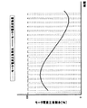
本発明に係るビート量補正手段の第3の実施形態を図5に示す。図5において、モータ電流検出値ijの正負を判別するモータ電流正負判別部51と、モータ電流正負判別部51の出力値をもとにモータ電流正負割合εjを設定するモータ電流正負割合設定部52と、モータ電流正負割合εjを積分器31により積分する際に積分回数カウンター33にてモータ電流正負割合εjの1周期における積分回数Nを記憶しておき、モータ電流正負割合平均演算部53では積分器31の出力値(モータ電流正負比率εjの積分値)を積分回数カウンター33で記憶した積分回数Nで除算することでモータ電流正負割合平均値εj_meanを導出するものである。
(Embodiment 3)
FIG. 5 shows a third embodiment of the beat amount correcting means according to the present invention. In FIG. 5, a motor current positive / negative determining
ここで、モータ電流正負割合εjは数(11)のように設定するものとする。 Here, the motor current positive / negative ratio ε j is set as shown in Expression (11).
また、モータ電流変動量補正係数演算部34ではモータ電流正負割合平均値εj_meanの逆位相成分を導出することで各相のビート量補正係数kbjを数(13)の演算により導出する。
In addition, the motor current variation correction
また、図11に図5のビート量補正手段におけるモータ電流正負割合εjとモータ電流変動量△ijとの関係を示す。モータ電流正負割合εjに対して数(12)の演算によりモータ電流正負割合平均値εj_meanを導出することでモータ電流変動量△KBが導出されているのがわかる。 The relation between motor current negative ratio epsilon j and the motor current fluctuation amount △ i j in the beat amount correction means in FIG. 5 in FIG. 11. Motor current fluctuation amount by deriving a motor current negative ratio average value epsilon j _ mean the operation of the equation (12) with respect to the motor current negative ratio ε j △ K B is seen that are derived.
以上により、モータ電流検出値をそのまま平均演算するのに対して、マイコン等の演算手段における演算量やメモリの低減を図れ、演算手段のコスト低減を図ることが可能である。 As described above, while the average calculation of the motor current detection value is performed as it is, the amount of calculation and the memory in the calculation means such as a microcomputer can be reduced, and the cost of the calculation means can be reduced.
(実施の形態4)
本発明に係るビート量補正手段の第4の実施の形態を図6に示す。図5のビート量補正手段と同じ構成要素は同一符号で示してあり、その説明は重複するので省略し、ここでは異なる部分についてのみ述べる。
(Embodiment 4)
FIG. 6 shows a fourth embodiment of the beat amount correcting means according to the present invention. The same components as those of the beat amount correcting means in FIG. 5 are denoted by the same reference numerals, and the description thereof will be omitted because they are duplicated, and only different portions will be described here.
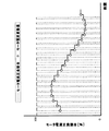
図6において、モータ電流正負割合平均演算部53はインバータ運転周波数f1の周期毎にモータ電流正負割合平均値εj_meanを導出し、モータ電流正負割合平均値保存部61はモータ電流正負割合平均演算部53で導出したモータ電流正負割合平均値値εj_meanのM周期前の値までを保存するものであり、モータ電流正負割合平均値値εj_meanを導出している期間においては少なくとも1周期前(1〜M周期前)のモータ電流正負割合平均値値εj_meanをモータ電流変動量△ijとし、モータ電流正負割合平均値εj_meanを導出している期間が終了すればモータ電流変動量△ijを新たに更新するものである。
6, a motor current positive / negative ratio
なお、モータ電流正負割合平均値保存部61における保存するモータ電流正負割合平均値εj_meanの個数M(M周期前の値までを保存)に関しては、遅延時間や応答性を考慮してインバータ運転周波数f1や負荷条件に応じて予め設定しておく。 Regarding the number M of the motor current positive / negative ratio average values ε j — mean stored in the motor current positive / negative ratio average value storage unit 61 (up to a value before M cycles), the inverter is considered in consideration of delay time and responsiveness. set in advance according to the operation frequency f 1 and load conditions.
また、図12に図6のビート量補正手段におけるモータ電流正負割合εjとモータ電流変動量△ijとの関係を示す。図12において○印が演算により導出したモータ電流正負割合平均値εj_meanであり、モータ電流正負割合平均値εj_meanを導出している期間には1周期前のモータ電流正負割合平均値εj_meanをモータ電流変動量△ijとし、モータ電流正負割合平均値εj_meanを導出している期間が終了すればモータ電流変動量△ijを新たに更新するものである。 The relation between motor current negative ratio epsilon j and the motor current fluctuation amount △ i j in the beat amount correction means in FIG. 6 to FIG. In FIG. 12, the circles indicate the motor current positive / negative ratio average value ε j _mean derived by calculation, and during the period in which the motor current positive / negative ratio average value ε j _mean is derived, the motor current positive / negative ratio average one cycle before is derived. The value ε j — mean is defined as the motor current variation △ ij, and the motor current variation △ ij is updated anew when the period of deriving the motor current positive / negative ratio average ε j — mean ends. .
以上により、インバータの運転周波数の周期毎に正負の割合の平均値を導出しているため、インバータの運転周波数の周期毎にモータ電流検出値の平均値を導出する場合よりも更にマイコン等の演算手段における演算量やメモリの低減が図れ、演算手段のコスト低減を図ることが可能である。 As described above, since the average value of the positive / negative ratio is derived for each cycle of the inverter operating frequency, the calculation of the microcomputer and the like is further performed than when the average value of the motor current detection value is derived for each cycle of the inverter operating frequency. It is possible to reduce the calculation amount and the memory in the means, and it is possible to reduce the cost of the calculation means.
(実施の形態5)
本発明に係るビート量補正手段の第5の実施形態に関する具体的な方法について以下に説明する。
(Embodiment 5)
A specific method according to the fifth embodiment of the beat amount correcting means according to the present invention will be described below.
モータ電流検出値ijを1次遅れ演算することでモータ電流変動量△ijを導出するものであり、モータ電流変動量△ijは数(14)のように表される。 The motor current fluctuation amount △ ij is derived by performing a first-order lag operation on the motor current detection value ij , and the motor current fluctuation amount 表ij is represented by Expression (14).
以上により、モータ電流検出値を平均演算するのに対して、マイコン等の演算手段における演算量やメモリの低減が図れ、演算手段のコスト低減を図ることが可能である。 As described above, the amount of calculation and the amount of memory in the calculation means such as a microcomputer can be reduced as compared with the average calculation of the motor current detection value, and the cost of the calculation means can be reduced.
また、インバータの運転周波数f1が1次遅れ演算におけるカットオフ周波数fcut-offよりも小さい場合には数(14)によりモータ電流変動量△ijにはモータ電流検出値ijそのものが出力され、モータ電流変動量△ijを導出することができないため、インバータの運転周波数f1がカットオフ周波数fcut-offよりも大きい場合のみモータ電流変動量△ijの抑制をするものである。 If the operating frequency f 1 of the inverter is smaller than the cut-off frequency f cut-off in the first-order lag calculation, the motor current detection value ij itself is output to the motor current variation △ ij according to equation (14). is, it is not possible to derive a motor current fluctuation amount △ i j, in which the operating frequency f 1 of the inverter is the suppression of the cut-off frequency f is greater than the cut-off only the motor current fluctuation amount △ i j .
ここで、カットオフ周波数fcut-offと時定数Tの間には数(15)のような関係がある。 Here, there is a relationship as shown in Expression (15) between the cutoff frequency f cut-off and the time constant T.
また、上述の時定数Tの値が大きい場合には1次遅れ演算に伴なう時間遅れが大きくなり、実際のモータ電流変動量に対して1次遅れ演算により導出したモータ電流変動量は大きく遅れることとなり、モータ変動量の抑制効果が低減するため、1次遅れ演算に伴なう時間遅れを補償する遅延時間補償手段を備えるものである。 When the value of the time constant T is large, the time delay associated with the first-order lag calculation becomes large, and the motor current fluctuation amount derived by the first-order lag calculation becomes large with respect to the actual motor current fluctuation amount. Since the delay is delayed and the effect of suppressing the motor fluctuation amount is reduced, a delay time compensating means for compensating for a time delay accompanying the first-order delay calculation is provided.
以上により、1次遅れ演算に伴なう遅延時間を補償することができるため、モータ電流変動量の抑制効果の向上を図ることが可能である。 As described above, since the delay time associated with the first-order delay calculation can be compensated, it is possible to improve the effect of suppressing the motor current fluctuation amount.
(実施の形態6)
本発明に係るビート量補正手段の第6の実施形態を図7に示す。図7において、モータ電流検出値ijからモータ電流基本波成分i1jを検出する基本波電流検出手段71を備え、モータ電流検出値ijと基本波電流検出手段の出力値i1jとの差分によりモータ電流変動量を導出するものである。
(Embodiment 6)
FIG. 7 shows a sixth embodiment of the beat amount correcting means according to the present invention. 7, includes a fundamental current detecting means 71 for detecting the motor current fundamental wave component i 1j from the motor current detection value i j, the difference between the output value i 1j of the motor current detection value i j and the fundamental wave current detecting means Is used to derive the motor current variation.
ここで、モータ電流検出値ijは、実施の形態1の数(6)において上述しているように、概ね基本波成分i1jと変動量△ijとの合成とすることができる。 Here, the motor current detection value ij can be substantially a combination of the fundamental wave component i1j and the variation △ ij , as described above in the equation (6) of the first embodiment.
そのため、モータ電流検出値ijからモータ電流基本波成分i1jを検出し、モータ電流検出値ijとモータ電流基本波成分i1jとの差分により数(16)のようにモータ電流変動量△ijを導出することができる。 Therefore, by detecting the motor current fundamental wave component i 1j from the motor current detection value i j, the motor current fluctuation amount as in equation (16) by the difference between the motor current detection value i j and the motor current fundamental wave component i 1j △ ij can be derived.
また、図7における基本波電流検出手段71の第1の実施形態を図8に示す。 FIG. 8 shows a first embodiment of the fundamental wave current detecting means 71 in FIG.
図8において、3相/2相変換器81によりモータ電流検出値ijを3相交流から2相直流に変換し、3相/2相変換器81の出力値(モータ電流変動量△ijによりリプルを含んだ2相直流電流)をLPF72に通して完全な直流成分のみとし、LPF82の出力値(完全な直流成分)を2相/3相変換器83により2相直流から3相交流に変換することでモータ電流基本波成分i1jを検出するものである。
8, the motor current detection value ij is converted from a three-phase alternating current to a two-phase direct current by a three-phase / two-
ここで、3相/2相変換器81では数(17)の演算により、モータ電流検出値ijを3相交流から2相直流iγ、iδに変換する。
Here, the three-phase / two-
更に、2相/3相変換器83では数(19)の演算により、完全な直流成分である2相直流iγ0、iδ0から3相交流に変換する。
Further, the two-phase / three-
また、図13および図14に図6のビート量補正手段における動作説明図を示す。図13はモータ電流検出値ij、モータ電流基本波成分i1j、およびモータ電流変動量△ijの関係を示しており、図14は3相/2相変換器81の出力値である2相直流iγ、iδを示したものである。
FIGS. 13 and 14 are explanatory diagrams of the operation of the beat amount correcting means of FIG. FIG. 13 shows the relationship among the detected motor current value i j , the motor current fundamental wave component i 1j , and the motor current fluctuation amount △ ij , and FIG. 14 shows the
ここで、図13におけるモータ電流検出値ijを数(17)により演算することで図14の2相直流iγ、iδが得られ、2相直流iγ、iδをLPF82に通すことで完全な直流成分である2相直流iγ0、iδ0を導出し、2相直流iγ0、iδ0を数(19)により演算することで図13のモータ電流基本波成分i1jを得ている。更に、数(16)の差分演算によりモータ電流変動量△ijを得ることができる。
Here, the two-phase direct currents iγ and iδ in FIG. 14 are obtained by calculating the motor current detection value ij in FIG. 13 by the equation (17), and the two-phase direct currents iγ and iδ are passed through the
なお、LPF82による遅延時間や応答性に関しては、2相直流にて数(18)の演算を行なっているため、実際にモータ電流基本波成分i1jを導出する際にはLPF82による遅延時間の影響は少なくなっている。
In addition, regarding the delay time and the responsiveness of the
以上により、モータ電流検出値を3相交流から2相直流に変換した後で1次遅れ演算するため、リアルタイムにて時間遅れなくモータ電流変動量を導出することによりモータ電流変動量の抑制効果の向上を図ることが可能である。 As described above, since the motor current detection value is converted from the three-phase AC to the two-phase DC and then the first-order lag calculation is performed, the motor current fluctuation is derived in real time without a time delay, thereby suppressing the motor current fluctuation. It is possible to improve.
(実施の形態7)
本発明に係るビート量補正手段のモータ電流変動量の抑制における条件に関する具体的な方法を以下に説明する。
(Embodiment 7)
A specific method relating to the condition in the suppression of the motor current fluctuation amount of the beat amount correction means according to the present invention will be described below.
モータ電流変動量△ijが予め設定されたモータ電流変動量の設定値△iRよりも小さい場合にはモータ電流変動量△ijによる影響が小さいためモータ電流変動量△ijの抑制を止め、モータ電流変動量△ijが予め設定されたモータ電流変動量の設定値△iRよりも大きい場合のみモータ電流変動量△ijの抑制をするものである。 When the motor current fluctuation amount △ ij is smaller than a preset motor current fluctuation amount set value △ i R, the effect of the motor current fluctuation amount △ ij is small, so that the motor current fluctuation amount △ ij is suppressed. stop, in which the suppression of the motor current fluctuation amount △ i j only when the motor current fluctuation amount △ i j is greater than the set value △ i R of a preset motor current fluctuation amount.
以上により、モータ電流変動量が予め設定されたモータ電流変動量の設定値よりも大きい場合のみモータ電流変動量の抑制をすることで効果的にモータ電流変動量の抑制をすることができ、更にマイコン等の演算手段における演算量やメモリの低減が図れ、演算手段のコスト低減を図ることが可能である。 As described above, the motor current fluctuation can be effectively suppressed by suppressing the motor current fluctuation only when the motor current fluctuation is larger than the preset value of the motor current fluctuation. It is possible to reduce the amount of calculation and memory in the calculation means such as a microcomputer, and it is possible to reduce the cost of the calculation means.
また、インバータの運転周波数f1が予め設定されたインバータ運転周波数設定値f1Rよりも大きい場合のみモータ電流変動量△ijの抑制をするものである。 Moreover, in which the suppression of the motor current fluctuation amount △ i j only if the operation frequency f 1 of the inverter is greater than the inverter operation frequency setting value f 1R that is set in advance.
以上により、インバータの運転周波数が予め設定されたインバータ運転周波数設定値よりも大きい場合のみモータ電流変動量の抑制をすることで効果的にモータ電流変動量の抑制をすることができ、更にマイコン等の演算手段における演算量やメモリの低減が図れ、演算手段のコスト低減を図ることが可能である。 As described above, it is possible to effectively suppress the motor current fluctuation amount by suppressing the motor current fluctuation amount only when the inverter operation frequency is higher than the preset inverter operation frequency setting value. It is possible to reduce the amount of calculation and memory in the calculation means, and to reduce the cost of the calculation means.
更に、インダクションモータが加速あるいは減速するような過渡状態においてはモータ電流変動量△ijの抑制をしないものである。 Further, in a transient state in which the induction motor accelerates or decelerates, the motor current fluctuation amount △ ij is not suppressed.
以上により、インダクションモータが加速あるいは減速するような過渡状態でのモータ電流変動量の抑制をしないことでインダクションモータのモータ電流がハンチングするような不安定現象を回避することができ、更にマイコン等の演算手段における演算量やメモリの低減が図れ、演算手段のコスト低減を図ることが可能である。 As described above, an unstable phenomenon such as a hunting of the motor current of the induction motor can be avoided by not suppressing the motor current fluctuation amount in a transient state in which the induction motor accelerates or decelerates. It is possible to reduce the amount of calculation and memory in the calculating means, and it is possible to reduce the cost of the calculating means.
(実施の形態8)
本発明に係るモータ電流検出手段の第1の実施形態に関する具体的な方法について以下に説明する。
(Embodiment 8)
A specific method according to the first embodiment of the motor current detecting means according to the present invention will be described below.
モータ電流検出手段は、インバータの母線電流に流れる電流を検出する電流検出器を備えるものであり、インバータの過電流保護のためにインバータの直流母線に予め設けられているシャント抵抗を電流検出器として兼用し、電流検出器の出力値からキャリア周波数に同期してモータ電流を検出するものである。 The motor current detecting means includes a current detector that detects a current flowing in the bus current of the inverter, and uses a shunt resistor provided in advance in the DC bus of the inverter as a current detector for overcurrent protection of the inverter. Also, the motor current is detected in synchronization with the carrier frequency from the output value of the current detector.
ここで、本発明に係る電流検出手段の第1の動作説明図を図17に示す。図17において、インバータ母線電流はモータ電流のように時間軸(横軸)に対して連続値ではなく、インバータのキャリア周波数毎の離散値(インバータが通電する場合に正の電流がインバータに流れ込むため、図17のようにパルス状に変化する)であるため、図1におけるインバータ母線電流検出器13(インバータの過電流保護のために予め設けられているシャント抵抗)では、キャリア周期に同期してインバータ母線電流を検出する必要がある。 Here, a first operation explanatory diagram of the current detecting means according to the present invention is shown in FIG. In FIG. 17, the inverter bus current is not a continuous value on the time axis (horizontal axis) like the motor current, but a discrete value for each carrier frequency of the inverter (since a positive current flows into the inverter when the inverter is energized). 17), the inverter bus current detector 13 (a shunt resistor provided in advance for overcurrent protection of the inverter) in FIG. 1 synchronizes with the carrier cycle. It is necessary to detect the inverter bus current.
また、図17において破線で示すようにインバータ母線電流のピーク値(パルス波形における最大値)は概ねモータ電流と一致するため、インバータ母線電流のパルス波形のピーク値を検出することで、モータ電流を検出することが可能である。 Also, as shown by the broken line in FIG. 17, the peak value of the inverter bus current (the maximum value in the pulse waveform) substantially matches the motor current. Therefore, the motor current is detected by detecting the peak value of the pulse waveform of the inverter bus current. It is possible to detect.
なお、キャリア周波数に同期せずに電流を検出する場合には、インバータが通電していない時の電流を検出する可能性があり、モータ電流を検出することが困難となる。 If the current is detected without synchronizing with the carrier frequency, there is a possibility that the current is detected when the inverter is not energized, which makes it difficult to detect the motor current.
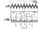
なお、図17における諸元としては、交流電源は220V(交流電源周波数は50Hz)、小容量リアクタのインダクタンス値は2mH、小容量コンデンサの容量は25μF、インバータ運転周波数は40Hz、インバータキャリア周波数は3.3kHzである。 The specifications in FIG. 17 are as follows: the AC power supply is 220 V (AC power supply frequency is 50 Hz), the inductance value of the small capacity reactor is 2 mH, the capacity of the small capacity capacitor is 25 μF, the inverter operation frequency is 40 Hz, and the inverter carrier frequency is 3 .3 kHz.
ここで、図1におけるモータ電流検出器14a、15aのように最低限2つの電流検出器を用いることで3相分のモータ電流を連続して検出できるのに対して、図17のように離散値で表される1相分のモータ電流を得ることしかできない。
Here, the motor currents for three phases can be continuously detected by using at least two current detectors like the motor
しかし、図18のように各相のモータ電流におけるモータ電流変動量は、時間差(横軸方向)はあるが大きさと周期は同じであるため、例えばU相のモータ電流検出値からモータ電流変動量を上述したビート量補正手段により導出し、V相およびW相のモータ電流変動量に関しては、インバータ運転周波数や負荷条件に応じて予め遅延時間を設定することで、U相のモータ電流変動量からV相およびW相のモータ電流変動量を得ることができる。 However, as shown in FIG. 18, the motor current fluctuation amount in the motor current of each phase has a time difference (horizontal axis direction) but the same magnitude and the same period. Is derived by the above-described beat amount correction means, and the V-phase and W-phase motor current fluctuations are set in advance in accordance with the inverter operating frequency and the load conditions, so that the delay time is set in advance from the U-phase motor current fluctuations. V-phase and W-phase motor current fluctuations can be obtained.
また、各相のモータ電流変動量を用いて、上述の数(10)の演算によりインダクションモータの印加電圧指令値を導出することができる。 Further, the applied voltage command value of the induction motor can be derived by the calculation of the above equation (10) using the motor current fluctuation amount of each phase.
なお、図18は本発明に係る電流検出手段の第2の動作説明図で、このときの諸元としては、交流電源は220V(交流電源周波数は50Hz)、小容量リアクタのインダクタンス値は0.5mH、小容量コンデンサの容量は10μF、インバータ運転周波数は96Hz、インバータキャリア周波数は5kHzである。 FIG. 18 is a diagram for explaining a second operation of the current detecting means according to the present invention. As the specifications at this time, the AC power supply is 220 V (AC power supply frequency is 50 Hz), and the inductance value of the small capacity reactor is 0.1. 5 mH, the capacity of the small capacitor is 10 μF, the inverter operating frequency is 96 Hz, and the inverter carrier frequency is 5 kHz.
上記の構成によって、電流センサを用いる場合に比べて、モータ電流検出手段にかかるコストを必要最小限とすることが可能である。
なお、前述の実施の形態ではインダクションモータについて説明を行なったが、本発明はその他のモータについても適用可能なものである。
With the above configuration, it is possible to minimize the cost required for the motor current detection unit as compared with the case where a current sensor is used.
Although the above embodiment has been described with respect to the induction motor, the present invention can be applied to other motors.
1 交流電源
2 ダイオードブリッジ
3 インバータ
4 インダクションモータ
5 小容量リアクタ
6 小容量コンデンサ
7 V/F制御パターン
8 モータ電圧指令作成手段
9 PN電圧検出手段
10 PN電圧補正手段
11 モータ電圧指令補正手段
12 PWM制御手段
13 インバータ母線電流検出器
14a、15b モータ電流検出器
15 モータ電流検出手段
16 ビート量補正手段
17 第2モータ電圧指令補正手段
31 積分器
32 モータ電流平均演算部
33 積分回数カウンター
34 モータ電流変動量補正係数演算部
41 モータ電流平均値保存部
51 モータ電流正負判別部
52 モータ電流正負割合設定部
53 モータ電流正負割合平均演算部
61 モータ電流正負割合平均値保存部
71 基本波電流検出手段
81 3相/2相変換器
82 LPF
83 2相/3相変換器
DESCRIPTION OF SYMBOLS 1
83 2-phase / 3-phase converter
Claims (20)
An air conditioner comprising: a converter device for converting AC power into DC power; and an inverter device for converting the DC power converted by the converter device into AC power having a variable voltage and a variable frequency and supplying the AC power to a compressor drive motor. An air conditioner, wherein the inverter device according to any one of claims 1 to 19 is used as the inverter device.
Priority Applications (3)
| Application Number | Priority Date | Filing Date | Title |
|---|---|---|---|
| JP2004074860A JP3955287B2 (en) | 2003-04-03 | 2004-03-16 | Inverter control device for motor drive and air conditioner |
| US10/814,190 US6958589B2 (en) | 2003-04-03 | 2004-04-01 | Inverter controller for driving motor and air conditioner using inverter controller |
| CNB200410034265XA CN1319268C (en) | 2003-04-03 | 2004-04-05 | Inverter controller for driving motor and air conditioner using the same |
Applications Claiming Priority (2)
| Application Number | Priority Date | Filing Date | Title |
|---|---|---|---|
| JP2003100008 | 2003-04-03 | ||
| JP2004074860A JP3955287B2 (en) | 2003-04-03 | 2004-03-16 | Inverter control device for motor drive and air conditioner |
Publications (2)
| Publication Number | Publication Date |
|---|---|
| JP2004320985A true JP2004320985A (en) | 2004-11-11 |
| JP3955287B2 JP3955287B2 (en) | 2007-08-08 |
Family
ID=33455429
Family Applications (1)
| Application Number | Title | Priority Date | Filing Date |
|---|---|---|---|
| JP2004074860A Expired - Fee Related JP3955287B2 (en) | 2003-04-03 | 2004-03-16 | Inverter control device for motor drive and air conditioner |
Country Status (3)
| Country | Link |
|---|---|
| US (1) | US6958589B2 (en) |
| JP (1) | JP3955287B2 (en) |
| CN (1) | CN1319268C (en) |
Cited By (17)
| Publication number | Priority date | Publication date | Assignee | Title |
|---|---|---|---|---|
| JP2005130690A (en) * | 2003-10-03 | 2005-05-19 | Matsushita Electric Ind Co Ltd | Motor driving inverter control device and air-conditioning apparatus |
| JP2006340486A (en) * | 2005-06-01 | 2006-12-14 | Fuji Electric Fa Components & Systems Co Ltd | Control device of motor |
| JP2007166690A (en) * | 2005-12-09 | 2007-06-28 | Hitachi Appliances Inc | Motor control device |
| WO2007116873A1 (en) * | 2006-04-03 | 2007-10-18 | Panasonic Corporation | Inverter device and air conditioner |
| WO2007125826A1 (en) * | 2006-04-24 | 2007-11-08 | Panasonic Corporation | Inverter device and air conditioner |
| JP2008109768A (en) * | 2006-10-25 | 2008-05-08 | Matsushita Electric Ind Co Ltd | Motor driving inverter controller and apparatus equipped therewith |
| JP2009147993A (en) * | 2007-12-11 | 2009-07-02 | Mitsubishi Electric Corp | Inverter controller, electric motor drive device and air conditioner |
| JP2009159750A (en) * | 2007-12-27 | 2009-07-16 | Panasonic Corp | Failure detector for motor |
| JP2009247099A (en) * | 2008-03-31 | 2009-10-22 | Denso Corp | Device for driving three-phase alternating-current synchronous motors |
| WO2010109520A1 (en) * | 2009-03-25 | 2010-09-30 | 三菱電機株式会社 | Device and method for rotating electric machine |
| WO2012086010A1 (en) * | 2010-12-21 | 2012-06-28 | 三菱電機株式会社 | Heat pump device, heat pump system, and method for controlling three-phase inverter |
| JP5658812B1 (en) * | 2013-11-19 | 2015-01-28 | シャープ株式会社 | Motor control device and refrigeration / air-conditioning device |
| US9543887B2 (en) | 2010-10-15 | 2017-01-10 | Mitsubishi Electric Corporation | Heat pump device, heat pump system, and method for controlling three-phase inverter |
| CN106549620A (en) * | 2016-10-26 | 2017-03-29 | 中冶南方(武汉)自动化有限公司 | A kind of Speed Sensorless Induction Motor vector control system low frequency processing method |
| US9829226B2 (en) | 2011-04-28 | 2017-11-28 | Mitsubishi Electric Corporation | Heat pump device, heat pump system, and method for controlling inverter |
| KR101910942B1 (en) | 2016-10-13 | 2018-10-23 | 오텍캐리어 주식회사 | Apparatus and method for sensing reversed phase of input source in air conditioner |
| JPWO2020217764A1 (en) * | 2019-04-23 | 2020-10-29 |
Families Citing this family (30)
| Publication number | Priority date | Publication date | Assignee | Title |
|---|---|---|---|---|
| KR100840733B1 (en) * | 2002-01-05 | 2008-06-24 | 엘지전자 주식회사 | Method and system for processing packet data in a communications system and receiving unit thereof |
| JP4129958B2 (en) * | 2002-09-13 | 2008-08-06 | 東京エレクトロン株式会社 | Rotation drive |
| GB2396491B (en) * | 2002-12-21 | 2005-11-30 | Dyson Ltd | Power conversion apparatus |
| JP2004289985A (en) * | 2003-03-25 | 2004-10-14 | Matsushita Electric Ind Co Ltd | Inverter controller for driving motor and air conditioner |
| JP3955285B2 (en) * | 2003-03-27 | 2007-08-08 | 松下電器産業株式会社 | Inverter control device for motor drive and air conditioner |
| JP3980005B2 (en) * | 2003-03-28 | 2007-09-19 | 松下電器産業株式会社 | Inverter control device for motor drive and air conditioner |
| JP3955286B2 (en) * | 2003-04-03 | 2007-08-08 | 松下電器産業株式会社 | Inverter control device for motor drive and air conditioner |
| GB2410847A (en) * | 2004-02-05 | 2005-08-10 | Dyson Ltd | Control of motor winding energisation according to rotor angle |
| JP3942605B2 (en) * | 2004-05-17 | 2007-07-11 | 東芝テック株式会社 | Motor control device and electrical equipment |
| US20060204383A1 (en) * | 2005-03-08 | 2006-09-14 | Hiroyuki Kushida | Electric vacuum cleaner |
| US8021469B2 (en) * | 2005-07-14 | 2011-09-20 | Access Business Group International Llc | Control methods for an air treatment system |
| JP4079962B2 (en) * | 2005-08-30 | 2008-04-23 | 株式会社東芝 | Electric vacuum cleaner |
| JP4856493B2 (en) * | 2006-08-07 | 2012-01-18 | 本田技研工業株式会社 | 2-motor simultaneous drive system and its control device |
| ES2385050T3 (en) * | 2006-08-31 | 2012-07-17 | Mitsubishi Electric Corporation | Electric motor drive device, and compressor drive device |
| ES2321675A1 (en) * | 2006-11-16 | 2009-06-09 | Ls Industrial Systems Co., Ltd. | Inverter bridge inverter device for alternating current motor. (Machine-translation by Google Translate, not legally binding) |
| US7495410B2 (en) * | 2007-01-30 | 2009-02-24 | Rockwell Automation Technologies, Inc. | Systems and methods for improved motor drive power factor control |
| JP4637148B2 (en) * | 2007-08-27 | 2011-02-23 | 株式会社日立製作所 | Power converter |
| GB201003456D0 (en) * | 2010-03-02 | 2010-04-14 | Trw Ltd | Current sensor error compensation |
| TWI403871B (en) | 2010-10-25 | 2013-08-01 | Ind Tech Res Inst | Feedback switching device and method for servo motor driving |
| DE102012215155A1 (en) * | 2012-08-27 | 2014-02-27 | Robert Bosch Gmbh | Method for regulating the current intensity of the electrical current flowing through an inductive load, and corresponding circuit arrangement |
| US8994320B2 (en) * | 2013-06-28 | 2015-03-31 | Eaton Corporation | System and method for controlling regenerating energy in an adjustable speed drive |
| JP5742980B1 (en) * | 2014-02-19 | 2015-07-01 | ダイキン工業株式会社 | Power converter control method |
| EP3121953B1 (en) * | 2014-03-15 | 2018-11-14 | Mitsubishi Electric Corporation | Motor drive control device, compressor, fan, and air-conditioning machine |
| JP6381777B2 (en) * | 2015-03-03 | 2018-08-29 | 三菱電機株式会社 | COMMUNICATION SYSTEM, TRANSMISSION DEVICE, AND RECEPTION DEVICE |
| JP6614825B2 (en) * | 2015-06-30 | 2019-12-04 | 日立ジョンソンコントロールズ空調株式会社 | Power conversion device, motor drive device, refrigeration device |
| JP6538477B2 (en) * | 2015-08-18 | 2019-07-03 | 日本電産サーボ株式会社 | Motor unit |
| CN105089999A (en) * | 2015-08-20 | 2015-11-25 | 深圳市建滔科技有限公司 | Power conversion efficiency improvement device of inverter compressor |
| JP6847775B2 (en) * | 2017-06-15 | 2021-03-24 | 三菱重工サーマルシステムズ株式会社 | Inverter device, air conditioner, control method and program of inverter device |
| JP6847774B2 (en) * | 2017-06-15 | 2021-03-24 | 三菱重工サーマルシステムズ株式会社 | Inverter device, air conditioner, control method and program of inverter device |
| KR102589033B1 (en) * | 2018-07-17 | 2023-10-17 | 현대자동차주식회사 | Apparatus and method for controlling inverter driving motor |
Family Cites Families (26)
| Publication number | Priority date | Publication date | Assignee | Title |
|---|---|---|---|---|
| JPH01144365A (en) * | 1987-11-27 | 1989-06-06 | Mitsubishi Electric Corp | Controlling circuit of inverter device |
| JP2780263B2 (en) * | 1988-02-23 | 1998-07-30 | 株式会社明電舎 | Vector control method and device for induction motor |
| US4992718A (en) * | 1989-09-11 | 1991-02-12 | Nihon Patent Electric Co., Ltd. | Electric floor cleaner with a soft start function |
| US5187419A (en) * | 1991-05-06 | 1993-02-16 | Allen-Bradley Company, Inc. | Electric motor control apparatus and method |
| US5206757A (en) * | 1992-02-13 | 1993-04-27 | Billy Cheng | Collapsible field glasses |
| US6002218A (en) * | 1992-11-20 | 1999-12-14 | Fujitsu General Limited | Control device for air conditioner |
| US5457375A (en) * | 1994-05-27 | 1995-10-10 | Emerson Electric Co. | Sensorless commutation controller for a poly-phase dynamoelectric machine |
| JPH0835712A (en) * | 1994-07-26 | 1996-02-06 | Fujitsu General Ltd | Controller for air conditioner |
| JP3295553B2 (en) * | 1994-10-05 | 2002-06-24 | 三菱電機株式会社 | Variable speed device |
| US5561595A (en) * | 1995-03-24 | 1996-10-01 | Magl Power Inc. | Power inverter with input line conditioning |
| JP3519540B2 (en) | 1996-03-28 | 2004-04-19 | 東芝キヤリア株式会社 | DC power supply and air conditioner |
| EP0945974B1 (en) * | 1998-03-23 | 2004-01-21 | Hitachi, Ltd. | Control apparatus of brushless motor and machine using brushless motor |
| JP4154679B2 (en) * | 1998-04-18 | 2008-09-24 | 株式会社安川電機 | Electric motor power failure processing method and control device therefor |
| US6229278B1 (en) * | 1999-09-29 | 2001-05-08 | Rockwell Technologies, Llc | Voltage and current limiting method and apparatus for a voltage/frequency drive |
| US6489692B1 (en) * | 1999-12-13 | 2002-12-03 | Capstone Turbine Corporation | Method and apparatus for controlling rotation of magnetic rotor |
| US6414455B1 (en) * | 2000-04-03 | 2002-07-02 | Alvin J. Watson | System and method for variable drive pump control |
| JP4465129B2 (en) * | 2000-07-14 | 2010-05-19 | パナソニック株式会社 | Brushless motor driving apparatus and driving method |
| KR20040090685A (en) * | 2002-03-22 | 2004-10-26 | 마츠시타 덴끼 산교 가부시키가이샤 | Synchronous reluctance motor control device |
| US6768284B2 (en) * | 2002-09-30 | 2004-07-27 | Eaton Corporation | Method and compensation modulator for dynamically controlling induction machine regenerating energy flow and direct current bus voltage for an adjustable frequency drive system |
| ES2300538T3 (en) * | 2002-12-12 | 2008-06-16 | Matsushita Electric Industrial Co., Ltd | MOTOR CONTROL DEVICE. |
| JP2004289985A (en) * | 2003-03-25 | 2004-10-14 | Matsushita Electric Ind Co Ltd | Inverter controller for driving motor and air conditioner |
| JP3955285B2 (en) * | 2003-03-27 | 2007-08-08 | 松下電器産業株式会社 | Inverter control device for motor drive and air conditioner |
| JP3980005B2 (en) * | 2003-03-28 | 2007-09-19 | 松下電器産業株式会社 | Inverter control device for motor drive and air conditioner |
| JP3955286B2 (en) * | 2003-04-03 | 2007-08-08 | 松下電器産業株式会社 | Inverter control device for motor drive and air conditioner |
| JP2004350493A (en) * | 2003-04-28 | 2004-12-09 | Matsushita Electric Ind Co Ltd | Inverter controller for driving motor and air conditioner using the same |
| US7078876B2 (en) * | 2003-07-07 | 2006-07-18 | Pentadyne Power Corporation | Feedforward controller for synchronous reluctance machines |
-
2004
- 2004-03-16 JP JP2004074860A patent/JP3955287B2/en not_active Expired - Fee Related
- 2004-04-01 US US10/814,190 patent/US6958589B2/en not_active Expired - Lifetime
- 2004-04-05 CN CNB200410034265XA patent/CN1319268C/en not_active Expired - Fee Related
Cited By (30)
| Publication number | Priority date | Publication date | Assignee | Title |
|---|---|---|---|---|
| JP2005130690A (en) * | 2003-10-03 | 2005-05-19 | Matsushita Electric Ind Co Ltd | Motor driving inverter control device and air-conditioning apparatus |
| JP4561219B2 (en) * | 2003-10-03 | 2010-10-13 | パナソニック株式会社 | Inverter control device for motor drive and air conditioner using the same |
| JP2006340486A (en) * | 2005-06-01 | 2006-12-14 | Fuji Electric Fa Components & Systems Co Ltd | Control device of motor |
| JP2007166690A (en) * | 2005-12-09 | 2007-06-28 | Hitachi Appliances Inc | Motor control device |
| JP5114387B2 (en) * | 2006-04-03 | 2013-01-09 | パナソニック株式会社 | Inverter device and air conditioner |
| WO2007116873A1 (en) * | 2006-04-03 | 2007-10-18 | Panasonic Corporation | Inverter device and air conditioner |
| WO2007125826A1 (en) * | 2006-04-24 | 2007-11-08 | Panasonic Corporation | Inverter device and air conditioner |
| JP5161766B2 (en) * | 2006-04-24 | 2013-03-13 | パナソニック株式会社 | Inverter device and air conditioner |
| JP2008109768A (en) * | 2006-10-25 | 2008-05-08 | Matsushita Electric Ind Co Ltd | Motor driving inverter controller and apparatus equipped therewith |
| JP2009147993A (en) * | 2007-12-11 | 2009-07-02 | Mitsubishi Electric Corp | Inverter controller, electric motor drive device and air conditioner |
| JP2009159750A (en) * | 2007-12-27 | 2009-07-16 | Panasonic Corp | Failure detector for motor |
| JP2009247099A (en) * | 2008-03-31 | 2009-10-22 | Denso Corp | Device for driving three-phase alternating-current synchronous motors |
| RU2481694C1 (en) * | 2009-03-25 | 2013-05-10 | Мицубиси Электрик Корпорейшн | Control device and control method of electric rotary machine |
| WO2010109520A1 (en) * | 2009-03-25 | 2010-09-30 | 三菱電機株式会社 | Device and method for rotating electric machine |
| US8610388B2 (en) | 2009-03-25 | 2013-12-17 | Mitsubishi Electric Corporation | Control apparatus and control method for electric rotating machine |
| US9543887B2 (en) | 2010-10-15 | 2017-01-10 | Mitsubishi Electric Corporation | Heat pump device, heat pump system, and method for controlling three-phase inverter |
| CN103270376A (en) * | 2010-12-21 | 2013-08-28 | 三菱电机株式会社 | Heat pump device, heat pump system, and method for controlling three-hase inverter |
| JP5490260B2 (en) * | 2010-12-21 | 2014-05-14 | 三菱電機株式会社 | HEAT PUMP DEVICE, HEAT PUMP SYSTEM, AND INVERTER CONTROL METHOD |
| WO2012086010A1 (en) * | 2010-12-21 | 2012-06-28 | 三菱電機株式会社 | Heat pump device, heat pump system, and method for controlling three-phase inverter |
| US9618249B2 (en) | 2010-12-21 | 2017-04-11 | Mitsubishi Electric Corporation | Heat pump device, heat pump system, and method for controlling three-phase inverter |
| US9829226B2 (en) | 2011-04-28 | 2017-11-28 | Mitsubishi Electric Corporation | Heat pump device, heat pump system, and method for controlling inverter |
| JP5658812B1 (en) * | 2013-11-19 | 2015-01-28 | シャープ株式会社 | Motor control device and refrigeration / air-conditioning device |
| WO2015075980A1 (en) * | 2013-11-19 | 2015-05-28 | シャープ株式会社 | Motor control device and refrigerating/air-conditioning device |
| KR101910942B1 (en) | 2016-10-13 | 2018-10-23 | 오텍캐리어 주식회사 | Apparatus and method for sensing reversed phase of input source in air conditioner |
| CN106549620A (en) * | 2016-10-26 | 2017-03-29 | 中冶南方(武汉)自动化有限公司 | A kind of Speed Sensorless Induction Motor vector control system low frequency processing method |
| CN106549620B (en) * | 2016-10-26 | 2019-07-23 | 中冶南方(武汉)自动化有限公司 | A kind of Speed Sensorless Induction Motor vector control system low frequency processing method |
| JPWO2020217764A1 (en) * | 2019-04-23 | 2020-10-29 | ||
| WO2020217764A1 (en) * | 2019-04-23 | 2020-10-29 | 日立オートモティブシステムズ株式会社 | Power conversion device, and electric vehicle system provided therewith |
| JP7158573B2 (en) | 2019-04-23 | 2022-10-21 | 日立Astemo株式会社 | POWER CONVERSION DEVICE AND ELECTRIC VEHICLE SYSTEM INCLUDING THE SAME |
| US11664756B2 (en) | 2019-04-23 | 2023-05-30 | Hitachi Astemo, Ltd. | Power conversion device and motor vehicle system including the same |
Also Published As
| Publication number | Publication date |
|---|---|
| CN1319268C (en) | 2007-05-30 |
| US20040232877A1 (en) | 2004-11-25 |
| JP3955287B2 (en) | 2007-08-08 |
| CN1543057A (en) | 2004-11-03 |
| US6958589B2 (en) | 2005-10-25 |
Similar Documents
| Publication | Publication Date | Title |
|---|---|---|
| JP3955287B2 (en) | Inverter control device for motor drive and air conditioner | |
| JP3955286B2 (en) | Inverter control device for motor drive and air conditioner | |
| KR101684706B1 (en) | Compensation Apparatus and Method for output current distortion of inverter | |
| JP5542609B2 (en) | Reactive power compensator | |
| JP3955285B2 (en) | Inverter control device for motor drive and air conditioner | |
| JP5365058B2 (en) | Control method of converter | |
| JP2004289985A (en) | Inverter controller for driving motor and air conditioner | |
| US11218107B2 (en) | Control device for power converter | |
| AU2008227057A1 (en) | Motor drive using flux adjustment to control power factor | |
| WO2006121093A1 (en) | Motor drive system control device and electric vehicle using the same | |
| JP5359245B2 (en) | Motor drive device | |
| JP3980005B2 (en) | Inverter control device for motor drive and air conditioner | |
| JP2004208397A (en) | Power converter and control method thereof | |
| JP4742590B2 (en) | Inverter controller for motor drive | |
| JP4561219B2 (en) | Inverter control device for motor drive and air conditioner using the same | |
| JP2006074951A (en) | Controller for ac motor | |
| JP2009284598A (en) | Controller for alternating-current motors | |
| JP2010193537A (en) | Motor drive controller and air conditioner | |
| JP2008228439A (en) | Power conversion apparatus and stabilization method therefor | |
| KR101996838B1 (en) | System of controlling induction motor | |
| JP2014023310A (en) | Converter system control method and control device | |
| JP5399955B2 (en) | Power converter and control method of power converter | |
| JP5306268B2 (en) | Power converter and control method of power converter | |
| JP6930275B2 (en) | Power converter | |
| JP6729250B2 (en) | Power converter controller |
Legal Events
| Date | Code | Title | Description |
|---|---|---|---|
| A621 | Written request for application examination |
Free format text: JAPANESE INTERMEDIATE CODE: A621 Effective date: 20050127 |
|
| A131 | Notification of reasons for refusal |
Free format text: JAPANESE INTERMEDIATE CODE: A131 Effective date: 20061031 |
|
| RD03 | Notification of appointment of power of attorney |
Free format text: JAPANESE INTERMEDIATE CODE: A7423 Effective date: 20061206 |
|
| A521 | Request for written amendment filed |
Free format text: JAPANESE INTERMEDIATE CODE: A523 Effective date: 20061213 |
|
| TRDD | Decision of grant or rejection written | ||
| A01 | Written decision to grant a patent or to grant a registration (utility model) |
Free format text: JAPANESE INTERMEDIATE CODE: A01 Effective date: 20070403 |
|
| A61 | First payment of annual fees (during grant procedure) |
Free format text: JAPANESE INTERMEDIATE CODE: A61 Effective date: 20070501 |
|
| R150 | Certificate of patent or registration of utility model |
Free format text: JAPANESE INTERMEDIATE CODE: R150 |
|
| FPAY | Renewal fee payment (event date is renewal date of database) |
Free format text: PAYMENT UNTIL: 20110511 Year of fee payment: 4 |
|
| FPAY | Renewal fee payment (event date is renewal date of database) |
Free format text: PAYMENT UNTIL: 20120511 Year of fee payment: 5 |
|
| FPAY | Renewal fee payment (event date is renewal date of database) |
Free format text: PAYMENT UNTIL: 20130511 Year of fee payment: 6 |
|
| FPAY | Renewal fee payment (event date is renewal date of database) |
Free format text: PAYMENT UNTIL: 20130511 Year of fee payment: 6 |
|
| FPAY | Renewal fee payment (event date is renewal date of database) |
Free format text: PAYMENT UNTIL: 20140511 Year of fee payment: 7 |
|
| LAPS | Cancellation because of no payment of annual fees |