JP2004308912A - Gasket for flange coupling - Google Patents
Gasket for flange coupling Download PDFInfo
- Publication number
- JP2004308912A JP2004308912A JP2004111994A JP2004111994A JP2004308912A JP 2004308912 A JP2004308912 A JP 2004308912A JP 2004111994 A JP2004111994 A JP 2004111994A JP 2004111994 A JP2004111994 A JP 2004111994A JP 2004308912 A JP2004308912 A JP 2004308912A
- Authority
- JP
- Japan
- Prior art keywords
- gasket
- core
- foil
- graphite
- layer
- Prior art date
- Legal status (The legal status is an assumption and is not a legal conclusion. Google has not performed a legal analysis and makes no representation as to the accuracy of the status listed.)
- Granted
Links
Images


Classifications
-
- B—PERFORMING OPERATIONS; TRANSPORTING
- B32—LAYERED PRODUCTS
- B32B—LAYERED PRODUCTS, i.e. PRODUCTS BUILT-UP OF STRATA OF FLAT OR NON-FLAT, e.g. CELLULAR OR HONEYCOMB, FORM
- B32B15/00—Layered products comprising a layer of metal
- B32B15/04—Layered products comprising a layer of metal comprising metal as the main or only constituent of a layer, which is next to another layer of the same or of a different material
- B32B15/08—Layered products comprising a layer of metal comprising metal as the main or only constituent of a layer, which is next to another layer of the same or of a different material of synthetic resin
- B32B15/082—Layered products comprising a layer of metal comprising metal as the main or only constituent of a layer, which is next to another layer of the same or of a different material of synthetic resin comprising vinyl resins; comprising acrylic resins
-
- B—PERFORMING OPERATIONS; TRANSPORTING
- B32—LAYERED PRODUCTS
- B32B—LAYERED PRODUCTS, i.e. PRODUCTS BUILT-UP OF STRATA OF FLAT OR NON-FLAT, e.g. CELLULAR OR HONEYCOMB, FORM
- B32B15/00—Layered products comprising a layer of metal
- B32B15/04—Layered products comprising a layer of metal comprising metal as the main or only constituent of a layer, which is next to another layer of the same or of a different material
- B32B15/08—Layered products comprising a layer of metal comprising metal as the main or only constituent of a layer, which is next to another layer of the same or of a different material of synthetic resin
- B32B15/092—Layered products comprising a layer of metal comprising metal as the main or only constituent of a layer, which is next to another layer of the same or of a different material of synthetic resin comprising epoxy resins
-
- B—PERFORMING OPERATIONS; TRANSPORTING
- B32—LAYERED PRODUCTS
- B32B—LAYERED PRODUCTS, i.e. PRODUCTS BUILT-UP OF STRATA OF FLAT OR NON-FLAT, e.g. CELLULAR OR HONEYCOMB, FORM
- B32B7/00—Layered products characterised by the relation between layers; Layered products characterised by the relative orientation of features between layers, or by the relative values of a measurable parameter between layers, i.e. products comprising layers having different physical, chemical or physicochemical properties; Layered products characterised by the interconnection of layers
- B32B7/04—Interconnection of layers
- B32B7/12—Interconnection of layers using interposed adhesives or interposed materials with bonding properties
-
- F—MECHANICAL ENGINEERING; LIGHTING; HEATING; WEAPONS; BLASTING
- F16—ENGINEERING ELEMENTS AND UNITS; GENERAL MEASURES FOR PRODUCING AND MAINTAINING EFFECTIVE FUNCTIONING OF MACHINES OR INSTALLATIONS; THERMAL INSULATION IN GENERAL
- F16J—PISTONS; CYLINDERS; SEALINGS
- F16J15/00—Sealings
- F16J15/02—Sealings between relatively-stationary surfaces
- F16J15/06—Sealings between relatively-stationary surfaces with solid packing compressed between sealing surfaces
- F16J15/10—Sealings between relatively-stationary surfaces with solid packing compressed between sealing surfaces with non-metallic packing
- F16J15/12—Sealings between relatively-stationary surfaces with solid packing compressed between sealing surfaces with non-metallic packing with metal reinforcement or covering
- F16J15/121—Sealings between relatively-stationary surfaces with solid packing compressed between sealing surfaces with non-metallic packing with metal reinforcement or covering with metal reinforcement
- F16J15/122—Sealings between relatively-stationary surfaces with solid packing compressed between sealing surfaces with non-metallic packing with metal reinforcement or covering with metal reinforcement generally parallel to the surfaces
-
- F—MECHANICAL ENGINEERING; LIGHTING; HEATING; WEAPONS; BLASTING
- F16—ENGINEERING ELEMENTS AND UNITS; GENERAL MEASURES FOR PRODUCING AND MAINTAINING EFFECTIVE FUNCTIONING OF MACHINES OR INSTALLATIONS; THERMAL INSULATION IN GENERAL
- F16L—PIPES; JOINTS OR FITTINGS FOR PIPES; SUPPORTS FOR PIPES, CABLES OR PROTECTIVE TUBING; MEANS FOR THERMAL INSULATION IN GENERAL
- F16L23/00—Flanged joints
- F16L23/16—Flanged joints characterised by the sealing means
- F16L23/18—Flanged joints characterised by the sealing means the sealing means being rings
-
- B—PERFORMING OPERATIONS; TRANSPORTING
- B32—LAYERED PRODUCTS
- B32B—LAYERED PRODUCTS, i.e. PRODUCTS BUILT-UP OF STRATA OF FLAT OR NON-FLAT, e.g. CELLULAR OR HONEYCOMB, FORM
- B32B2250/00—Layers arrangement
- B32B2250/40—Symmetrical or sandwich layers, e.g. ABA, ABCBA, ABCCBA
-
- B—PERFORMING OPERATIONS; TRANSPORTING
- B32—LAYERED PRODUCTS
- B32B—LAYERED PRODUCTS, i.e. PRODUCTS BUILT-UP OF STRATA OF FLAT OR NON-FLAT, e.g. CELLULAR OR HONEYCOMB, FORM
- B32B2311/00—Metals, their alloys or their compounds
- B32B2311/12—Copper
-
- B—PERFORMING OPERATIONS; TRANSPORTING
- B32—LAYERED PRODUCTS
- B32B—LAYERED PRODUCTS, i.e. PRODUCTS BUILT-UP OF STRATA OF FLAT OR NON-FLAT, e.g. CELLULAR OR HONEYCOMB, FORM
- B32B2311/00—Metals, their alloys or their compounds
- B32B2311/18—Titanium
-
- B—PERFORMING OPERATIONS; TRANSPORTING
- B32—LAYERED PRODUCTS
- B32B—LAYERED PRODUCTS, i.e. PRODUCTS BUILT-UP OF STRATA OF FLAT OR NON-FLAT, e.g. CELLULAR OR HONEYCOMB, FORM
- B32B2311/00—Metals, their alloys or their compounds
- B32B2311/20—Zinc
-
- B—PERFORMING OPERATIONS; TRANSPORTING
- B32—LAYERED PRODUCTS
- B32B—LAYERED PRODUCTS, i.e. PRODUCTS BUILT-UP OF STRATA OF FLAT OR NON-FLAT, e.g. CELLULAR OR HONEYCOMB, FORM
- B32B2311/00—Metals, their alloys or their compounds
- B32B2311/22—Nickel or cobalt
-
- B—PERFORMING OPERATIONS; TRANSPORTING
- B32—LAYERED PRODUCTS
- B32B—LAYERED PRODUCTS, i.e. PRODUCTS BUILT-UP OF STRATA OF FLAT OR NON-FLAT, e.g. CELLULAR OR HONEYCOMB, FORM
- B32B2311/00—Metals, their alloys or their compounds
- B32B2311/24—Aluminium
-
- B—PERFORMING OPERATIONS; TRANSPORTING
- B32—LAYERED PRODUCTS
- B32B—LAYERED PRODUCTS, i.e. PRODUCTS BUILT-UP OF STRATA OF FLAT OR NON-FLAT, e.g. CELLULAR OR HONEYCOMB, FORM
- B32B2581/00—Seals; Sealing equipment; Gaskets
Abstract
Description
本発明は、非特許文献1に規定の限界値以下の漏洩率を有するフランジ継手用の枠体付ガスケットに関する。 The present invention relates to a framed gasket for a flange joint having a leakage rate equal to or less than a limit value specified in Non-Patent Document 1.
黒鉛箔又は黒鉛を含む積層体でできたガスケットは、例えば化学産業において配管及び装置、発電所の蒸気管及び暖房設備に従来技術で使用されている。黒鉛箔は、黒鉛層間化合物の熱膨張、及びこの膨張により得られるアコーディオン形粒子を引続き圧縮することにより製造される。これらの粒子は、加圧下に圧縮する際に互いに埋め合わされ、接着剤を添加することなく箔又はプレートのような安定かつ柔軟な平面状形成物を製造できる。黒鉛箔は高温及び腐食媒質に耐えるので、比較的僅かな流体透過性、高い圧縮率、優れたスプリングバック性及び加圧下での極めて僅かなクリープ傾向を特徴とする。 Gaskets made of graphite foil or laminates containing graphite are used in the prior art, for example in the chemical industry for piping and equipment, steam pipes and heating installations of power plants. Graphite foil is produced by thermal expansion of a graphite intercalation compound and subsequent compression of the accordion-shaped particles obtained by this expansion. These particles fill each other when compressed under pressure, and can produce a stable and flexible planar formation such as a foil or plate without the addition of an adhesive. Since graphite foil withstands high temperatures and corrosive media, it is characterized by relatively low fluid permeability, high compressibility, excellent springback and a very low tendency to creep under pressure.
黒鉛からなるガスケットの機械的安定性は、金属(シート又は箔)からなる補強挿入物を2つの黒鉛箔間に埋め込むことで高め得る。従って従来技術に基づく全層厚で1〜4mmのガスケットには、大抵の場合厚さ数100μmの複数の黒鉛箔間に金属挿入物を埋め込んだ積層体が使用されている。 The mechanical stability of a graphite gasket can be increased by embedding a reinforcing insert made of metal (sheet or foil) between two graphite foils. Therefore, gaskets with a total layer thickness of 1 to 4 mm according to the prior art generally use a laminate in which a metal insert is embedded between a plurality of graphite foils several hundred μm thick.
複数の金属層と黒鉛層が交互に重なる層接合材の製造方法は、特許文献1から公知である。金属層と黒鉛層との間に、接着剤なしで不可分の結合を、有機珪素化合物、過フッ化物又は金属石けんの群からの界面活性物質を薄層の形で少なくとも1つの接合すべき表面上に塗布し、該表面を引続き接触させ、圧力及び熱の作用で互いに接合することで形成できる。 A method for manufacturing a layer bonding material in which a plurality of metal layers and graphite layers alternately overlap is known from Patent Document 1. An inseparable bond between the metal layer and the graphite layer without an adhesive is formed on at least one surface to be joined in the form of a thin layer of a surface-active substance from the group of organosilicon compounds, perfluorides or metallic soaps. , The surfaces being brought into contact, and joined together by the action of pressure and heat.
特許文献1の例4は、かかる層接合材の特徴的な構成を開示する。該層接合材は、各々厚さ0.25mmの4層の黒鉛箔と、各々厚さ0.05mmの3層のアルミニウムシートから成り、各シートは2枚の黒鉛箔間に埋め込まれ、交互に重なる積層体を形成する。 Example 4 of Patent Document 1 discloses a characteristic configuration of such a layer bonding material. The layer bonding material is composed of four layers of graphite foil each having a thickness of 0.25 mm and three layers of aluminum sheets each having a thickness of 0.05 mm, and each sheet is embedded between two graphite foils and alternately. An overlapping stack is formed.
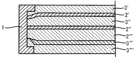
このようなフランジ継手用積層体からなるガスケットの漏洩率は、その環状ガスケットの内周および/又は外周を枠体1で囲んだ場合、明らかに低下する。厚さの等しい4枚の黒鉛箔3'、3''、3'''及び3''''と、それらの2枚の黒鉛箔の間に埋め込んだ、厚さの等しい3枚の金属箔2'、2''及び2'''とからなるガスケットの断面を図1に示す。その枠体1は、この層接合材の全ての層を包み込んでいる。この枠体は、拡散バリヤの役目をする。枠体下にその黒鉛は特に強力に圧縮され、その結果枠体1と外側黒鉛層3'もしくは(3'''')間に十分に流体の漏れない封止が達成される。
The leakage rate of the gasket made of such a laminated body for a flange joint is clearly reduced when the inner and / or outer periphery of the annular gasket is surrounded by the frame 1. Four equal
この原理に基づき組立てられた、流体漏れに対し高度の要求を満たすガスケットは、例えば商品名“SIGRAFLEX”(高圧用)の名称で市販されている(非特許文献3参照)。このガスケットは積層された同じ厚さの複数の黒鉛箔から成り、箔間に金属箔の補強挿入物が埋め込まれている。典型的には、環状ガスケット体の内周および/又は外周範囲は、層接合材の全ての層を包み込む枠体で囲まれている。例えばヨーロッパで使用されている標準的フランジ継手の封止に好適な厚さ2mmのガスケットは、各々厚さ0.5mmの4層の黒鉛箔と、箔間に埋め込んだ、各々厚さ0.05mmの3層の特殊鋼の箔からなる。このガスケットは、特殊鋼の枠体を備える。全体として7層の積層体からなるこのガスケットの気体透過率は、(VDI基準要綱2440で測定して)0.9×10-5kPa×1/(s×m)であり、極めて低い。その漏洩率(非特許文献1に基づく)は、フランジ継手に対する10-5kPa×1/(s×m)の限界値を下回るものである。この限界値を守ることは、VDI基準要綱2440に基づく試験、即ちその漏れ測定が室温でのヘリウム質量分光法で、ヘリウム差圧1バール及び表面圧力30MPaにより行われる。 A gasket assembled based on this principle and meeting a high demand for fluid leakage is commercially available, for example, under the name of “SIGRAFLEX” (for high pressure) (see Non-Patent Document 3). The gasket is made up of a plurality of graphite foils of the same thickness laminated with a metal foil reinforcing insert embedded between the foils. Typically, the inner and / or outer peripheral area of the annular gasket body is surrounded by a frame enclosing all layers of the layer bonding material. For example, a 2 mm thick gasket suitable for sealing standard flange joints used in Europe has four layers of graphite foil, each 0.5 mm thick, and 0.05 mm thick each embedded between the foils. Consisting of three layers of special steel foil. This gasket includes a special steel frame. The gasket of this gasket, which consists of a total of seven layers of laminate, has an extremely low gas permeability of 0.9 × 10 −5 kPa × 1 / (s × m) (measured according to the VDI standard 2440). The leakage rate (based on Non-Patent Document 1) is below the limit value of 10 −5 kPa × 1 / (s × m) for the flange joint. Observing these limits is carried out according to the VDI standard 2440, ie the leak measurement is carried out by helium mass spectroscopy at room temperature with a helium differential pressure of 1 bar and a surface pressure of 30 MPa.
上記の原理に基づき組立てられた比較的厚いガスケットも公知である。例えば、厚さ4mmのガスケットは、同じ厚さの8層の黒鉛箔と、7層の埋め込み金属箔、即ちこの層接合材は合計15層からなる。 Relatively thick gaskets assembled according to the above principles are also known. For example, a gasket with a thickness of 4 mm has eight layers of graphite foil of the same thickness and seven layers of embedded metal foil, that is, a total of 15 layers of this layer bonding material.
工業分野において、設備の作動と操作の確実性及び、特に2002年に新たに決議されたTA空気(清浄保持空気、非特許文献2)の導入に関する環境保護の理由から、低い漏洩率の遵守を可能にするガスケットの需要が増大している。
本発明は、従来技術に比べて構造の改善された、即ち灰分の少ない高純度の黒鉛箔の分量を削減しおよび/又は厚さの一定した金属挿入物の層の分量を削減し、30MPaの表面圧力及び1バールのヘリウム差圧で10-5kPa×1/(s×m)以下の漏洩率を示す、TA空気の要求を満たすフランジ継手用ガスケットを提供することを課題とする。 The present invention reduces the volume of high purity graphite foil with improved structure, i.e., low ash content, and / or reduces the volume of a layer of metal insert of constant thickness, as compared to the prior art, and reduces the An object of the present invention is to provide a gasket for a flange joint satisfying the requirement of TA air, which shows a leak rate of 10 −5 kPa × 1 / (s × m) or less at a surface pressure and a helium differential pressure of 1 bar.
この課題は、本発明の請求項1に記載のガスケットの組立て構成、更に従属請求項に記載のガスケットの有利な特徴及び実施形態により解決される。 This object is solved by an assembly of a gasket according to claim 1 of the present invention, as well as by advantageous features and embodiments of the gasket according to the dependent claims.
フランジ継手用ガスケットの層接合材に、そのコアの黒鉛箔の面積比重量に対する上載せ層の黒鉛箔の面積比重量の比を1:3〜1:7とすることにより、TA空気の限界値を超えない漏洩率を示すフランジ継手用ガスケットを提供できる。 By limiting the ratio of the area specific weight of the graphite foil of the overlying layer to the area specific weight of the graphite foil of the core to 1: 3 to 1: 7 in the layer joining material of the flange joint gasket, the limit value of TA air is obtained. Can be provided.
本発明によるガスケットの更なる特徴、詳細及び利点を図面に基づき以下に述べる。 Further features, details and advantages of the gasket according to the invention are described below with reference to the drawings.
図2は、本発明によるガスケットの断面を示す。このガスケットは、孔の空いていない2枚の金属箔2'、2''間に埋め込んだ、少なくとも1つの黒鉛箔の層から成り、耐圧性の厚い平面状内部コア5を含む。該コアに面していない金属箔の表面は、コアに比べて薄い黒鉛箔からなる上載せ層4'、4''で覆われている。典型的には、環状ガスケット体の封止すべき空隙に接する内周範囲は、枠体1で囲まれている。枠体1は、ガスケットを構成する積層体の全ての層を包み込んでいる。この内側の枠体に、補助的に外側の枠体を設けてもよい(図示せず)。この外側枠体により、ガスケットの吹き抜け安全性が高まる。
FIG. 2 shows a cross section of a gasket according to the invention. This gasket comprises at least one layer of graphite foil embedded between two
上載せ層を構成する黒鉛箔の面積比重量と、コアを構成する黒鉛箔のそれとの比率が1:3〜1:7であることが、本発明のガスケットの機能に決定的に重要である。面積比重量(g/m2)は、黒鉛箔の厚さ(m)と密度(g/m3)の積で生ずる。この層の面積比重量は、本発明による層接合材中でそれら層が果たす種々の機能に応じて選択される。 It is crucial to the function of the gasket of the present invention that the ratio of the area specific weight of the graphite foil constituting the overlying layer to that of the graphite foil constituting the core is 1: 3 to 1: 7. . The area specific weight (g / m 2 ) is obtained by multiplying the thickness (m) and the density (g / m 3 ) of the graphite foil. The area specific weight of the layers is selected according to the various functions they perform in the layer bonding material according to the invention.
黒鉛箔からなる外側上載せ層の機能は、フランジにぴったり適合し、かつ漏れ路の発生を十分に阻止すべく、枠体により流体漏れのない封止を形成することにある。枠体下にある上載せ層の範囲は、特に強く加圧されるので、この範囲の黒鉛の流体透過度は明らかに低下する。上載せ層中の黒鉛箔の面積比重量が低ければ低い程、透過率は低くなる。従って本発明によるガスケットの上載せ層には、最高で350g/m2、特に150〜250g/m2の面積比重量の黒鉛箔を使用する。従来技術では、少なくとも0.7g/cm3の密度を有する黒鉛箔を製造でき、従って350g/m2の最大の面積比重量で、最高で0.5mmの厚さの上載せ層が生じる。しかし、拡散侵入する粒子を、通過の困難な拡散バリヤである金属箔に、できるだけ迅速にぶつけるために、この黒鉛箔の上載せ層をできるだけ薄く形成することが望ましい。それ故これらの上載せ層は、特に有利な実施形態では0.15〜0.35mmの厚さである。この上載せ層の最低の厚さは、フランジにぴったり適合し、かつフランジの粗面性を補償できる上載せ層の機能により決定される。鋼製フランジの典型的な最大粗面度は、Rz=80〜90μmである。従って最低で0.15mmの厚さを有する上載せ層は、そのフランジの表面の粗面性を補償するのに十分である。 The function of the outer overlaying layer of graphite foil is to form a fluid-tight seal by means of the frame so that it fits snugly on the flange and sufficiently prevents the formation of leak paths. The area of the overlying layer below the frame is particularly strongly pressed, so that the fluid permeability of graphite in this area is clearly reduced. The lower the area specific weight of the graphite foil in the overlying layer, the lower the transmittance. Thus the layer placed on the gasket according to the present invention, up to 350 g / m 2, in particular using a graphite foil weight per unit area of 150 to 250 g / m 2. In the prior art, graphite foils having a density of at least 0.7 g / cm 3 can be produced, thus producing a top layer with a maximum area specific weight of 350 g / m 2 and a thickness of at most 0.5 mm. However, it is desirable to form the overlying layer of the graphite foil as thin as possible so that the particles that diffuse and penetrate against the metal foil, which is a diffusion barrier that is difficult to pass through, as quickly as possible. The overlying layers are therefore in a particularly advantageous embodiment 0.15 to 0.35 mm thick. The minimum thickness of this overlying layer is determined by the function of the overlying layer that fits snugly on the flange and can compensate for the roughness of the flange. A typical maximum roughness of a steel flange is Rz = 80-90 μm. Thus, an overlayer having a minimum thickness of 0.15 mm is sufficient to compensate for the roughness of the surface of the flange.
これらの外側上載せ層は、封止されるべき空隙を貫流する媒質と接触しており、従ってそれらは特に純粋で、従ってまた(DIN第51903により規定されている)化学的に耐性な、最高でも1%の灰分の黒鉛箔(即ちその質量に対し少なくとも99%の黒鉛含有量に相当する)で製造する必要がある。更に灰分の少ない高純度の黒鉛箔を上載せ層に使用することは、フランジの汚染による腐食の危険性を低減するために必要である。特に高純度の黒鉛からなる上載せ層を製造する必要性に関して、コアに比べて上載せ層の厚さを削減することは、経済的理由からも有利である。 These outer overlying layers are in contact with the medium flowing through the cavity to be sealed, so that they are particularly pure and therefore also chemically resistant (as defined by DIN 51903). However, it must be manufactured from graphite foil with an ash content of 1% (that is, corresponding to a graphite content of at least 99% of its mass). Furthermore, the use of high purity graphite foil with low ash content in the overlying layer is necessary to reduce the risk of corrosion due to contamination of the flange. Particularly with respect to the need to manufacture an overlayer made of high-purity graphite, reducing the thickness of the overlayer relative to the core is also advantageous for economic reasons.
本発明による層接合材中のコアの機能は、ガスケットの機械的要求を満たす、即ち十分な圧縮性と戻り弾性を保証し、かつこのガスケットに、フランジ間の空隙を満たすのに必要な厚さを与えることにある。コアの十分な耐圧強度は、ガスケットのコア中の黒鉛箔の面積比重量が1500g/m2を越えない場合に生ずる。コアに600〜1200g/m2の面積比重量と、0.7〜1.3g/cm3の密度を持つ黒鉛箔を使用するとよい。 The function of the core in the layer joint according to the invention is to fulfill the mechanical requirements of the gasket, i.e. to ensure sufficient compressibility and return resilience and to provide the gasket with the necessary thickness to fill the gap between the flanges. Is to give. Sufficient pressure resistance of the core occurs when the area specific weight of the graphite foil in the gasket core does not exceed 1500 g / m 2 . It is preferable to use a graphite foil having an area specific weight of 600 to 1200 g / m 2 and a density of 0.7 to 1.3 g / cm 3 for the core.
表面が金属箔2'、2''、そして封止すべき空隙に面するエッジが枠体1により密封されているため、本発明によるガスケットのコア5は封止すべき空隙を貫流する媒質と接触しない。従ってこの黒鉛のコア5に、不透過性及び化学的安定性に関して高度の要求を設定する必要はない。従ってこのコアを、上載せ層に使用する箔に比べて純度の低い、しかしそのガスケットに対する機能的要求に相応した黒鉛箔から製造すると経済的に有利である。96%以上の黒鉛含有量、即ち灰分の質量比が4%以下の黒鉛箔が適する。
The
このコアの媒質不透過性に対する要求が低いことは、本発明による層接合材の内部に金属製の付加的拡散バリヤのない比較的厚い黒鉛層が存在することを許容する。このコアの厚さは、フランジ継手の封止に必要なガスケットの全厚に依存する。ヨーロッパで一般に使用されているフランジ継手には、通常厚さ2mmのガスケットを必要とし、米国で一般に使用されているフランジ継手には、通常厚さ1.6mmのガスケットを必要とする。 The low requirement for medium impermeability of this core allows the presence of a relatively thick graphite layer without additional diffusion barriers made of metal inside the layer joint according to the invention. The thickness of this core depends on the total gasket thickness required to seal the flange joint. Flange joints commonly used in Europe typically require a 2 mm thick gasket, while flange joints commonly used in the United States typically require a 1.6 mm thick gasket.
本発明により、1.5mm以上の厚さのコアを有するガスケットを、そのコアが各々最高で1500g/m2の面積比重量を有する、少なくとも2枚の黒鉛箔の層から組立て、その際個々の黒鉛箔の層間に、各々1枚の金属挿入物を埋め込むようにして形成すると特に有利である。このコアの黒鉛箔の層間に埋込まれた金層挿入物は、コアが、その両表面の金属箔及び枠体により完全に囲まれており、拡散バリヤの役目をしなくてもよいので、突起付きシート又はエキスパンデッドメタルシートとしても形成可能である。従ってこのコアの黒鉛箔の層間に埋め込まれる金属挿入物とは、孔の空いていない金属箔のことも、突起付きシート又はエキスパンデッドメタルシートのことも意味する。 According to the invention, a gasket having a core with a thickness of 1.5 mm or more is assembled from at least two layers of graphite foil, each core having an area specific weight of at most 1500 g / m 2 , wherein the individual It is particularly advantageous to form one metal insert between the layers of the graphite foil. The gold layer insert embedded between the layers of graphite foil of the core has a core completely surrounded by the metal foil and the frame on both surfaces thereof, and does not have to serve as a diffusion barrier. It can also be formed as a sheet with projections or an expanded metal sheet. Therefore, the metal insert embedded between the layers of the graphite foil of the core means a metal foil having no holes, a sheet with projections, or an expanded metal sheet.
同様に、複数の黒鉛箔の層を含むコアを持つ本発明によるガスケットの機能にとって、上載せ層を構成する黒鉛箔の面積比重量が350g/m2以下、コア中の層を構成する黒鉛箔の面積比重量が1500g/m2以下、上載せ層の面積比重量と、コア中の層の黒鉛箔の面積比重量との比率が、1:3〜1:7であることが極めて重要である。 Similarly, for the function of the gasket according to the present invention having a core including a plurality of layers of graphite foil, the graphite foil constituting the layer in the core has an area specific weight of 350 g / m 2 or less for the graphite foil constituting the overlying layer. the weight per unit area is 1500 g / m 2 or less, and the weight per unit area of the upper loaded layer, the ratio of the weight per unit area of the graphite foil layer in the core is 1: 3 to 1: is it is extremely important 7 is there.
例えば本発明による厚さ4mmのガスケットは、以下に記載の層構造を有する。即ち厚さ0.25mmの黒鉛箔からなる上載せ層4'、拡散バリヤとしての厚さ0.05mmの金属箔2'、各々厚さ1.1mmの3枚の黒鉛箔5'、5''、5'''からなるコア5、それらの間に補強のために埋め込む厚さ0.05mmの金属箔、突起付きシート又はエキスパンデッドメタルシート6'、6''、拡散バリヤとしての厚さ0.05mmのもう1つの金属箔2''及び厚さ0.25mmの黒鉛箔からなる上載せ層4''を有する。このコア(5)内及び上載せ層4'、4''内の黒鉛箔5'、5''、5'''の密度は、各々1g/cm3である。図3はこの層構造の断面を概略的に示しており、その際コア5の黒鉛箔5'、5''、5'''間に金属箔6'、6''が埋め込まれている。全ての層は枠体1により囲まれている。
For example, a gasket having a thickness of 4 mm according to the present invention has the following layer structure. That is, an
一方で枠体とフランジの共同作用で流体に対する媒質安定性と封止の機能の分離、他方で本発明による層接合材の上載せ層とコア間の圧縮率、戻り弾性率及び空隙充填度は、このガスケットの漏洩率を増やすことなく、黒鉛層の厚さに関し高純度の黒鉛の灰分を低下させ、かつ拡散バリヤとして必要な金属製の中間層の数を削減することを可能にする。 On the one hand, the separation of the medium stability and the function of sealing by the joint action of the frame body and the flange, and on the other hand, the compressibility, return elastic modulus and gap filling degree between the upper layer and the core of the layer bonding material according to the present invention are This makes it possible to reduce the ash content of high-purity graphite with respect to the thickness of the graphite layer and to reduce the number of metal intermediate layers required as a diffusion barrier without increasing the gasket leakage rate.
コアと上載せ層の間に埋め込んだ金属箔の機能は、内部の拡散バリヤの作用以外に、この層結合物の機械的な補強にある。典型的には、特殊鋼、鋼、鉄、アルミニウム、ニッケル、銅、チタン又は亜鉛或いはニッケル、銅、アルミニウム又は亜鉛の合金からなる金属箔又は金属シートを使用する。これら金属挿入物の厚さは0.02〜1mm、特に0.02〜0.2mmである。 The function of the metal foil embedded between the core and the overlying layer, apart from the action of the internal diffusion barrier, is the mechanical reinforcement of this layer combination. Typically, a metal foil or sheet made of special steel, steel, iron, aluminum, nickel, copper, titanium or zinc or an alloy of nickel, copper, aluminum or zinc is used. The thickness of these metal inserts is between 0.02 and 1 mm, in particular between 0.02 and 0.2 mm.
多層のコアを使用する場合、コア中で黒鉛箔5'、5''、5'''・・・の個々の層間にある金属挿入物6'、6''・・・を、それらが拡散バリヤとして働く必要がないので、突起付きシート、又はエキスパンデッドメタルシートとしても形成してもよい。本発明によるガスケットの機能にとって、場合によっては多層の平面状コアの両側表面が孔の空いていない拡散バリヤの役目をする金属箔2'、2''により覆われていることは極めて重要である。
If a multi-layer core is used, they diffuse
本発明によるガスケットのコアと上載せ層の黒鉛箔の製造は、例えば硫化水素黒鉛又は窒化黒鉛等の黒鉛の塩の黒鉛層間化合物の熱膨張と、引続いての、結合剤を添加しない、この発泡体の加圧下での平面状形成物への圧縮により行われる。 The production of the graphite foil of the gasket core and of the overlying layer according to the invention comprises the thermal expansion of a graphite intercalation compound of a salt of graphite, such as, for example, hydrogen sulfide graphite or graphite nitride, and subsequent addition of a binder. This is done by compressing the foam into a planar formation under pressure.
本発明による層接合材の製造は、特許文献1に記載の方法で行うとよい。その方法の利点は、それら層間の不可分の結合を形成するため、老化、軟化及び/又は化学的又は熱的分解に曝される従来の接着剤を必要としない点にある。その代わりに、金属箔及び黒鉛箔の接合に、例えば有機珪素化合物、金属石けん又は過フッ化物の群からの境界面活性物質の接着仲介物質を使用する。これら物質は、被覆した面を、圧力と温度の作用下に接合すべき面と接触させた際、例えば数nmに過ぎない層厚で互いに接合すべき金属表面と黒鉛表面上に極く薄く塗布した場合、不可分の結合を形成する。この接合すべき表面を接触させ続けると、圧力及び熱の作用により互いに結合する。 The production of the layer bonding material according to the present invention may be performed by the method described in Patent Document 1. The advantage of that method is that it does not require conventional adhesives that are subject to aging, softening and / or chemical or thermal decomposition to form inseparable bonds between the layers. Instead, an adhesive mediator of an interface active from the group of, for example, organosilicon compounds, metallic soaps or perfluorides is used for joining the metal foil and the graphite foil. These substances are applied very thinly on the metal and graphite surfaces to be joined together, for example with a layer thickness of only a few nm, when the coated surfaces are brought into contact with the surfaces to be joined under the action of pressure and temperature. Form an inseparable bond. When the surfaces to be joined are kept in contact, they are joined together by the action of pressure and heat.
或いはまた、本発明による層接合材を、そのガスケットの使用条件が許すなら、個々の層を公知の接着剤で上下に接着することによっても製造することもできる。 Alternatively, the layer joining material according to the invention can also be produced by gluing the individual layers up and down with known adhesives, if the conditions of use of the gasket permit.
コアの黒鉛箔と、その間に埋め込む突起付きシートとの接合は、公知方法で、この突起付きシートの突出する表面構造が黒鉛箔に侵入および/又は黒鉛が孔に侵入するように、加圧することにより形成される。 Bonding between the graphite foil of the core and the protruding sheet embedded therebetween is performed by a known method by applying pressure so that the protruding surface structure of the protruding sheet enters the graphite foil and / or the graphite penetrates the holes. Formed by
外側上載せ層の流体に対する緊密度は、公知方法で樹脂を含浸させることにより更に改善できる。適した含浸剤は、例えば硬化触媒の作用下にフラン樹脂に縮合するフルフリルアルコール、フェノール樹脂、エポキシ樹脂及びアクリル樹脂がある。 The tightness of the outer overlayer to the fluid can be further improved by impregnating the resin in a known manner. Suitable impregnants include, for example, furfuryl alcohol, phenolic resins, epoxy resins and acrylic resins which condense to furan resins under the action of a curing catalyst.
本発明による層接合材の内周範囲及び場合により外周範囲の枠体は、公知の方法で形成される。通常フランジ継手のガスケットには、厚さ0.15〜0.2mmの特殊鋼からなる枠体が使用される。しかし先に記載した厚さ0.1mmの枠体を持つ積層体でできたガスケットは、特に低い漏洩率を示すことを確認した。本発明によるガスケットに適した枠体材料は、クロムニッケル鋼、ニッケル、ニッケル合金、銅及びアルミニウムである。 The frame of the inner and, if appropriate, outer peripheral area of the layer bonding material according to the invention is formed in a known manner. Usually, a frame made of special steel having a thickness of 0.15 to 0.2 mm is used for the gasket of the flange joint. However, it was confirmed that the gasket made of the laminate having a frame having a thickness of 0.1 mm described above exhibited a particularly low leak rate. Frame materials suitable for the gasket according to the invention are chromium-nickel steel, nickel, nickel alloys, copper and aluminum.
表1に記載の組立て構成及び特殊鋼(材料番号第1.4401)からなる厚さ0.1mmの内側枠体を有するガスケットの漏洩率をVDI基準要綱2440に基づき検査した。

測定のため、DINフランジ、DN40とPN40の間にこのガスケットを平坦な密封枠体で挟み込んだ。粗面深さはRz≦6.3μmであった。ボルトを30MPaの面圧を生じる力で締付けた。組立て後、このフランジセットを300℃の炉内で48時間放置した。冷却後、絶対漏洩率をヘリウム漏洩検出器(質量分光測計)で1バールのヘリウム差圧で測定した。比漏洩率を検出すべく、実際に加圧した封止面の平均周径を参考にした。 For measurement, this gasket was sandwiched between a DIN flange, DN40 and PN40 with a flat sealing frame. The roughness depth was Rz ≦ 6.3 μm. The bolt was tightened with a force that produces a surface pressure of 30 MPa. After assembly, this flange set was left in a furnace at 300 ° C. for 48 hours. After cooling, the absolute leak rate was measured with a helium leak detector (mass spectrometer) at a helium differential pressure of 1 bar. In order to detect the specific leak rate, the average peripheral diameter of the sealing surface actually pressed was referred to.
本発明によるガスケットの比漏洩率は、0.95×10-5kPa×1/(s×m)であった。従って本発明によるガスケットはTA空気に規定される1×10-5kPa×1/(s×m)の限界値を下回るものである。 The specific leakage rate of the gasket according to the present invention was 0.95 × 10 −5 kPa × 1 / (s × m). Therefore, the gasket according to the present invention is below the limit value of 1 × 10 −5 kPa × 1 / (s × m) specified for TA air.
本発明のガスケットは著しく低い漏洩率を持ち、例えば化学産業や発電所において有 効に使用可能である。 The gaskets of the present invention have a significantly lower leakage rate and can be used effectively in, for example, the chemical industry and power plants.
1 枠体、2'、2''、2'' 金属箔、3'、3''、3'''、3'''' 黒鉛箔、4'、4'' 黒鉛箔からなる上載せ層、5 コア、5'、5''、5''' コア中の黒鉛箔の層、6'、6'' コア中の金属箔 1 Frame, 2 ', 2' ', 2' 'metal foil, 3', 3 '', 3 '' ', 3' '' 'graphite foil, 4', 4 '' overlaying layer made of graphite foil Layer of graphite foil in 5 core, 5 ', 5 ", 5"' core, metal foil in 6 ', 6 "core
Claims (16)
16. Gasket according to one of the claims 1 to 15, characterized in that the gasket leakage rate is ≤ 10-5 kPaxl / (sxm), measured according to (VDI Standards) 2440.
Applications Claiming Priority (1)
| Application Number | Priority Date | Filing Date | Title |
|---|---|---|---|
| DE10316262A DE10316262A1 (en) | 2003-04-08 | 2003-04-08 | Seal for flange connections |
Publications (2)
| Publication Number | Publication Date |
|---|---|
| JP2004308912A true JP2004308912A (en) | 2004-11-04 |
| JP4570897B2 JP4570897B2 (en) | 2010-10-27 |
Family
ID=32864403
Family Applications (1)
| Application Number | Title | Priority Date | Filing Date |
|---|---|---|---|
| JP2004111994A Expired - Fee Related JP4570897B2 (en) | 2003-04-08 | 2004-04-06 | Gasket for flange joint |
Country Status (6)
| Country | Link |
|---|---|
| US (1) | US6962349B2 (en) |
| EP (1) | EP1466722B1 (en) |
| JP (1) | JP4570897B2 (en) |
| CN (1) | CN100425889C (en) |
| AT (1) | ATE325709T1 (en) |
| DE (2) | DE10316262A1 (en) |
Cited By (4)
| Publication number | Priority date | Publication date | Assignee | Title |
|---|---|---|---|---|
| JP2009526185A (en) * | 2006-02-10 | 2009-07-16 | カルボヌ ロレーヌ コンポザン | Airtight gasket with flexible graphite / metal multilayers adapted for high temperature use conditions |
| JP2010513811A (en) * | 2006-12-22 | 2010-04-30 | エスゲーエル カーボン ソシエタス ヨーロピア | Seal material |
| CN101692353B (en) * | 2009-09-30 | 2011-11-23 | 马志刚 | Leakage-detectable constant-stress sealing gasket |
| KR101094149B1 (en) * | 2010-10-20 | 2011-12-14 | 김광일 | Inflated graphite gasket and method of preparing same |
Families Citing this family (19)
| Publication number | Priority date | Publication date | Assignee | Title |
|---|---|---|---|---|
| DE102005019250B3 (en) * | 2005-04-24 | 2006-09-28 | Köthener Spezialdichtungen GmbH | Chamber ring to protect seal zone of gland packing has wall metal and non-metal washers stuck to each other by industrial glue |
| US20070014965A1 (en) * | 2005-06-24 | 2007-01-18 | Robert Chodelka | Gasket material for use in high pressure, high temperature apparatus |
| US9327875B2 (en) | 2010-10-29 | 2016-05-03 | S.C. Johnson & Son, Inc. | Reclosable bag having a loud sound during closing |
| US8568031B2 (en) | 2011-02-22 | 2013-10-29 | S.C. Johnson & Son, Inc. | Clicking closure device for a reclosable pouch |
| JP5884447B2 (en) * | 2011-11-30 | 2016-03-15 | オイレス工業株式会社 | Cylindrical gasket, manufacturing method thereof, and plug-in type exhaust pipe joint using the cylindrical gasket |
| US10059156B2 (en) | 2012-04-09 | 2018-08-28 | Dana Heavy Vehicle Systems Group, Llc | Hub assembly for a tire inflation system |
| US9446637B2 (en) | 2012-04-09 | 2016-09-20 | Dana Heavy Vehicle Systems Group, Llc | Tire inflation system |
| FR2993032B1 (en) * | 2012-07-04 | 2014-07-11 | Valeo Sys Controle Moteur Sas | ENGINE CONTROL VALVE WITH IMPROVED SEALING |
| DE102012220310A1 (en) * | 2012-11-08 | 2014-05-08 | Sgl Carbon Se | Layer composite |
| DE102013002753B3 (en) * | 2013-02-19 | 2014-06-05 | Fachhochschule Münster | Method for producing a sealing element |
| KR101848185B1 (en) * | 2013-07-15 | 2018-04-11 | 페더럴-모걸 엘엘씨 | Cylinder head gaskets with push-rod eyelets |
| CA2821897C (en) * | 2013-07-26 | 2016-08-16 | Ray Arbesman | Metal and graphite laminate |
| CN103671919A (en) * | 2013-11-21 | 2014-03-26 | 南通高盛机械制造有限公司 | Sealing gasket |
| EP3290754B1 (en) | 2016-08-30 | 2023-06-14 | Frenzelit GmbH | Soft material seal with surround |
| CN107143711A (en) * | 2017-06-22 | 2017-09-08 | 合肥聪亨新型建材科技有限公司 | A kind of flange gasket |
| CN108458182A (en) * | 2018-04-23 | 2018-08-28 | 上海冀晟能源科技有限公司 | The sealing element and its manufacturing method of high temperature resistant melt salt corrosion |
| CN108893048B (en) * | 2018-07-19 | 2020-10-09 | 宁波信幸隆密封制品有限公司 | Composite material and preparation process thereof |
| DE102020214437A1 (en) * | 2020-11-17 | 2022-05-19 | Sgl Carbon Se | poetry |
| US11703013B1 (en) | 2022-03-03 | 2023-07-18 | Caterpillar Inc. | Engine head gasket having anti-preignition wrap and method of making same |
Citations (8)
| Publication number | Priority date | Publication date | Assignee | Title |
|---|---|---|---|---|
| JPH01158269A (en) * | 1987-12-15 | 1989-06-21 | Hitachi Chem Co Ltd | Graphitic gasket material |
| JPH0592574U (en) * | 1991-07-15 | 1993-12-17 | 住友化学工業株式会社 | gasket |
| JPH06257673A (en) * | 1993-02-26 | 1994-09-16 | Dana Corp | Gasket for internal combustion engine |
| JPH06321518A (en) * | 1993-03-25 | 1994-11-22 | Sigri Great Lakes Carbon Gmbh | Preparation of metal-graphite laminated material |
| JPH0727231A (en) * | 1993-07-16 | 1995-01-27 | Nippon Valqua Ind Ltd | Expansion graphite sheet gasket |
| JPH08245947A (en) * | 1995-03-10 | 1996-09-24 | Hitachi Chem Co Ltd | Metallic gasket material, its production and metallic gasket |
| JPH11286070A (en) * | 1998-02-04 | 1999-10-19 | Sgl Technik Gmbh | Metal-reinforced graphite laminate material |
| JP2002256083A (en) * | 2000-12-07 | 2002-09-11 | Sgl Carbon Ag | Acrylic-resin impregnated material composed of expanded graphite |
Family Cites Families (2)
| Publication number | Priority date | Publication date | Assignee | Title |
|---|---|---|---|---|
| HUT66295A (en) * | 1991-09-13 | 1994-11-28 | Meillor Sa | Sheet gasket, particularly for internal combustion engines, and method for manufacturing the same |
| DE19804289A1 (en) * | 1998-02-04 | 1999-08-05 | Sgl Technik Gmbh | Laminate gasket with flare |
-
2003
- 2003-04-08 DE DE10316262A patent/DE10316262A1/en not_active Withdrawn
-
2004
- 2004-03-22 DE DE502004000524T patent/DE502004000524D1/en not_active Expired - Lifetime
- 2004-03-22 AT AT04006802T patent/ATE325709T1/en active
- 2004-03-22 EP EP04006802A patent/EP1466722B1/en not_active Expired - Lifetime
- 2004-04-06 JP JP2004111994A patent/JP4570897B2/en not_active Expired - Fee Related
- 2004-04-06 US US10/819,380 patent/US6962349B2/en not_active Expired - Fee Related
- 2004-04-08 CN CNB200410032518XA patent/CN100425889C/en not_active Expired - Fee Related
Patent Citations (8)
| Publication number | Priority date | Publication date | Assignee | Title |
|---|---|---|---|---|
| JPH01158269A (en) * | 1987-12-15 | 1989-06-21 | Hitachi Chem Co Ltd | Graphitic gasket material |
| JPH0592574U (en) * | 1991-07-15 | 1993-12-17 | 住友化学工業株式会社 | gasket |
| JPH06257673A (en) * | 1993-02-26 | 1994-09-16 | Dana Corp | Gasket for internal combustion engine |
| JPH06321518A (en) * | 1993-03-25 | 1994-11-22 | Sigri Great Lakes Carbon Gmbh | Preparation of metal-graphite laminated material |
| JPH0727231A (en) * | 1993-07-16 | 1995-01-27 | Nippon Valqua Ind Ltd | Expansion graphite sheet gasket |
| JPH08245947A (en) * | 1995-03-10 | 1996-09-24 | Hitachi Chem Co Ltd | Metallic gasket material, its production and metallic gasket |
| JPH11286070A (en) * | 1998-02-04 | 1999-10-19 | Sgl Technik Gmbh | Metal-reinforced graphite laminate material |
| JP2002256083A (en) * | 2000-12-07 | 2002-09-11 | Sgl Carbon Ag | Acrylic-resin impregnated material composed of expanded graphite |
Cited By (4)
| Publication number | Priority date | Publication date | Assignee | Title |
|---|---|---|---|---|
| JP2009526185A (en) * | 2006-02-10 | 2009-07-16 | カルボヌ ロレーヌ コンポザン | Airtight gasket with flexible graphite / metal multilayers adapted for high temperature use conditions |
| JP2010513811A (en) * | 2006-12-22 | 2010-04-30 | エスゲーエル カーボン ソシエタス ヨーロピア | Seal material |
| CN101692353B (en) * | 2009-09-30 | 2011-11-23 | 马志刚 | Leakage-detectable constant-stress sealing gasket |
| KR101094149B1 (en) * | 2010-10-20 | 2011-12-14 | 김광일 | Inflated graphite gasket and method of preparing same |
Also Published As
| Publication number | Publication date |
|---|---|
| EP1466722B1 (en) | 2006-05-10 |
| ATE325709T1 (en) | 2006-06-15 |
| CN100425889C (en) | 2008-10-15 |
| DE502004000524D1 (en) | 2006-06-14 |
| JP4570897B2 (en) | 2010-10-27 |
| US6962349B2 (en) | 2005-11-08 |
| DE10316262A1 (en) | 2004-11-11 |
| EP1466722A1 (en) | 2004-10-13 |
| CN1540195A (en) | 2004-10-27 |
| US20040201182A1 (en) | 2004-10-14 |
Similar Documents
| Publication | Publication Date | Title |
|---|---|---|
| JP4570897B2 (en) | Gasket for flange joint | |
| US6565099B1 (en) | Multilayered gasket with eyelit | |
| CA2261102C (en) | Metal-reinforced graphite multilayer sheet | |
| US9140362B2 (en) | Flexible graphite/metal multilayer gaskets suited to high-temperature service conditions | |
| CA2618798C (en) | Low stress to seal eptfe gasket material | |
| US20090302552A1 (en) | Sealing Material | |
| KR20100082858A (en) | Gasket | |
| CN201069024Y (en) | composite gasket | |
| KR20100082857A (en) | Gasket | |
| EP2733777B1 (en) | Seal between metal and ceramic conduits | |
| US6399204B1 (en) | Flexible multi-layer gasketing product | |
| JPH0727231A (en) | Expansion graphite sheet gasket | |
| JPS6256380A (en) | Ceramic-metal joined member | |
| CA2558739C (en) | Low stress to seal expanded ptfe gasket tape | |
| JP4918462B2 (en) | gasket | |
| JPH0592574U (en) | gasket | |
| KR101094149B1 (en) | Inflated graphite gasket and method of preparing same | |
| Weil et al. | Development of a compliant seal for use in planar solid oxide fuel cells | |
| US20240001650A1 (en) | Seal | |
| JP7090017B2 (en) | gasket | |
| JP2001173784A (en) | Heat resistant sealant | |
| JP4918461B2 (en) | gasket | |
| Underwood et al. | Seal between metal and ceramic conduits | |
| JP2023518259A (en) | gasket | |
| GB2391599A (en) | Impovements in multilayered pipes |
Legal Events
| Date | Code | Title | Description |
|---|---|---|---|
| A621 | Written request for application examination |
Free format text: JAPANESE INTERMEDIATE CODE: A621 Effective date: 20070308 |
|
| A977 | Report on retrieval |
Free format text: JAPANESE INTERMEDIATE CODE: A971007 Effective date: 20090918 |
|
| A131 | Notification of reasons for refusal |
Free format text: JAPANESE INTERMEDIATE CODE: A131 Effective date: 20090929 |
|
| A601 | Written request for extension of time |
Free format text: JAPANESE INTERMEDIATE CODE: A601 Effective date: 20091228 |
|
| A602 | Written permission of extension of time |
Free format text: JAPANESE INTERMEDIATE CODE: A602 Effective date: 20100106 |
|
| A521 | Request for written amendment filed |
Free format text: JAPANESE INTERMEDIATE CODE: A523 Effective date: 20100129 |
|
| A131 | Notification of reasons for refusal |
Free format text: JAPANESE INTERMEDIATE CODE: A131 Effective date: 20100511 |
|
| A521 | Request for written amendment filed |
Free format text: JAPANESE INTERMEDIATE CODE: A523 Effective date: 20100514 |
|
| TRDD | Decision of grant or rejection written | ||
| A01 | Written decision to grant a patent or to grant a registration (utility model) |
Free format text: JAPANESE INTERMEDIATE CODE: A01 Effective date: 20100713 |
|
| A01 | Written decision to grant a patent or to grant a registration (utility model) |
Free format text: JAPANESE INTERMEDIATE CODE: A01 |
|
| A61 | First payment of annual fees (during grant procedure) |
Free format text: JAPANESE INTERMEDIATE CODE: A61 Effective date: 20100811 |
|
| FPAY | Renewal fee payment (event date is renewal date of database) |
Free format text: PAYMENT UNTIL: 20130820 Year of fee payment: 3 |
|
| R150 | Certificate of patent or registration of utility model |
Free format text: JAPANESE INTERMEDIATE CODE: R150 |
|
| LAPS | Cancellation because of no payment of annual fees |