JP2004308418A - Snow removing machine provided with system using surface treatment material - Google Patents
Snow removing machine provided with system using surface treatment material Download PDFInfo
- Publication number
- JP2004308418A JP2004308418A JP2004106916A JP2004106916A JP2004308418A JP 2004308418 A JP2004308418 A JP 2004308418A JP 2004106916 A JP2004106916 A JP 2004106916A JP 2004106916 A JP2004106916 A JP 2004106916A JP 2004308418 A JP2004308418 A JP 2004308418A
- Authority
- JP
- Japan
- Prior art keywords
- machine
- processing material
- snow
- housing
- area
- Prior art date
- Legal status (The legal status is an assumption and is not a legal conclusion. Google has not performed a legal analysis and makes no representation as to the accuracy of the status listed.)
- Pending
Links
- 239000000463 material Substances 0.000 title claims abstract description 249
- 238000004381 surface treatment Methods 0.000 title claims abstract description 32
- 239000007788 liquid Substances 0.000 claims abstract description 35
- 238000011282 treatment Methods 0.000 claims abstract description 35
- 239000007787 solid Substances 0.000 claims abstract description 12
- 238000007710 freezing Methods 0.000 claims abstract description 10
- 239000007921 spray Substances 0.000 claims description 50
- 238000010438 heat treatment Methods 0.000 claims description 22
- 238000005507 spraying Methods 0.000 claims description 12
- 239000011236 particulate material Substances 0.000 claims description 10
- 230000002528 anti-freeze Effects 0.000 claims description 8
- 230000007246 mechanism Effects 0.000 claims description 8
- 239000000843 powder Substances 0.000 claims description 5
- 238000002347 injection Methods 0.000 claims description 4
- 239000007924 injection Substances 0.000 claims description 4
- 238000003756 stirring Methods 0.000 claims description 3
- 239000002245 particle Substances 0.000 claims 4
- 238000007599 discharging Methods 0.000 claims 2
- 239000011344 liquid material Substances 0.000 claims 2
- 239000006185 dispersion Substances 0.000 claims 1
- 230000008014 freezing Effects 0.000 abstract description 5
- 230000002265 prevention Effects 0.000 abstract 2
- 239000003795 chemical substances by application Substances 0.000 description 16
- 230000007480 spreading Effects 0.000 description 10
- 235000002639 sodium chloride Nutrition 0.000 description 9
- 239000012530 fluid Substances 0.000 description 8
- TWRXJAOTZQYOKJ-UHFFFAOYSA-L Magnesium chloride Chemical compound [Mg+2].[Cl-].[Cl-] TWRXJAOTZQYOKJ-UHFFFAOYSA-L 0.000 description 6
- OKKJLVBELUTLKV-UHFFFAOYSA-N Methanol Chemical compound OC OKKJLVBELUTLKV-UHFFFAOYSA-N 0.000 description 6
- 238000000034 method Methods 0.000 description 5
- 229920000728 polyester Polymers 0.000 description 5
- 150000003839 salts Chemical class 0.000 description 5
- 230000008859 change Effects 0.000 description 4
- 230000007423 decrease Effects 0.000 description 4
- 108010053481 Antifreeze Proteins Proteins 0.000 description 3
- FAPWRFPIFSIZLT-UHFFFAOYSA-M Sodium chloride Chemical compound [Na+].[Cl-] FAPWRFPIFSIZLT-UHFFFAOYSA-M 0.000 description 3
- 238000005260 corrosion Methods 0.000 description 3
- 230000007797 corrosion Effects 0.000 description 3
- 229910001629 magnesium chloride Inorganic materials 0.000 description 3
- 239000004033 plastic Substances 0.000 description 3
- 229920000642 polymer Polymers 0.000 description 3
- 230000008569 process Effects 0.000 description 3
- 230000004044 response Effects 0.000 description 3
- 239000011780 sodium chloride Substances 0.000 description 3
- 238000009825 accumulation Methods 0.000 description 2
- 230000004913 activation Effects 0.000 description 2
- 230000005540 biological transmission Effects 0.000 description 2
- 230000015572 biosynthetic process Effects 0.000 description 2
- 238000007664 blowing Methods 0.000 description 2
- 238000004140 cleaning Methods 0.000 description 2
- 239000004020 conductor Substances 0.000 description 2
- 238000010586 diagram Methods 0.000 description 2
- 239000000499 gel Substances 0.000 description 2
- 230000005484 gravity Effects 0.000 description 2
- 230000001788 irregular Effects 0.000 description 2
- 230000008018 melting Effects 0.000 description 2
- 238000002844 melting Methods 0.000 description 2
- 229910052751 metal Inorganic materials 0.000 description 2
- 239000002184 metal Substances 0.000 description 2
- 239000000203 mixture Substances 0.000 description 2
- SCVFZCLFOSHCOH-UHFFFAOYSA-M potassium acetate Chemical compound [K+].CC([O-])=O SCVFZCLFOSHCOH-UHFFFAOYSA-M 0.000 description 2
- 239000000126 substance Substances 0.000 description 2
- 239000002699 waste material Substances 0.000 description 2
- UXVMQQNJUSDDNG-UHFFFAOYSA-L Calcium chloride Chemical compound [Cl-].[Cl-].[Ca+2] UXVMQQNJUSDDNG-UHFFFAOYSA-L 0.000 description 1
- DGAQECJNVWCQMB-PUAWFVPOSA-M Ilexoside XXIX Chemical compound C[C@@H]1CC[C@@]2(CC[C@@]3(C(=CC[C@H]4[C@]3(CC[C@@H]5[C@@]4(CC[C@@H](C5(C)C)OS(=O)(=O)[O-])C)C)[C@@H]2[C@]1(C)O)C)C(=O)O[C@H]6[C@@H]([C@H]([C@@H]([C@H](O6)CO)O)O)O.[Na+] DGAQECJNVWCQMB-PUAWFVPOSA-M 0.000 description 1
- 241001465754 Metazoa Species 0.000 description 1
- 241000289371 Ornithorhynchus anatinus Species 0.000 description 1
- 230000003213 activating effect Effects 0.000 description 1
- 230000009286 beneficial effect Effects 0.000 description 1
- 230000008901 benefit Effects 0.000 description 1
- 239000012267 brine Substances 0.000 description 1
- 239000001110 calcium chloride Substances 0.000 description 1
- 229910001628 calcium chloride Inorganic materials 0.000 description 1
- 239000002131 composite material Substances 0.000 description 1
- 238000013016 damping Methods 0.000 description 1
- 230000000593 degrading effect Effects 0.000 description 1
- 230000032798 delamination Effects 0.000 description 1
- 230000000694 effects Effects 0.000 description 1
- -1 for example Substances 0.000 description 1
- 231100001261 hazardous Toxicity 0.000 description 1
- 239000003112 inhibitor Substances 0.000 description 1
- 235000013379 molasses Nutrition 0.000 description 1
- 229910000403 monosodium phosphate Inorganic materials 0.000 description 1
- 235000019799 monosodium phosphate Nutrition 0.000 description 1
- 230000008520 organization Effects 0.000 description 1
- 238000005192 partition Methods 0.000 description 1
- 239000002861 polymer material Substances 0.000 description 1
- 235000011056 potassium acetate Nutrition 0.000 description 1
- WFIZEGIEIOHZCP-UHFFFAOYSA-M potassium formate Chemical compound [K+].[O-]C=O WFIZEGIEIOHZCP-UHFFFAOYSA-M 0.000 description 1
- 238000005086 pumping Methods 0.000 description 1
- 238000002407 reforming Methods 0.000 description 1
- 230000000717 retained effect Effects 0.000 description 1
- 239000011734 sodium Substances 0.000 description 1
- 229910052708 sodium Inorganic materials 0.000 description 1
- AJPJDKMHJJGVTQ-UHFFFAOYSA-M sodium dihydrogen phosphate Chemical compound [Na+].OP(O)([O-])=O AJPJDKMHJJGVTQ-UHFFFAOYSA-M 0.000 description 1
- 239000001488 sodium phosphate Substances 0.000 description 1
- HPALAKNZSZLMCH-UHFFFAOYSA-M sodium;chloride;hydrate Chemical compound O.[Na+].[Cl-] HPALAKNZSZLMCH-UHFFFAOYSA-M 0.000 description 1
- 239000011343 solid material Substances 0.000 description 1
- 238000006467 substitution reaction Methods 0.000 description 1
Images


Classifications
-
- E—FIXED CONSTRUCTIONS
- E01—CONSTRUCTION OF ROADS, RAILWAYS, OR BRIDGES
- E01H—STREET CLEANING; CLEANING OF PERMANENT WAYS; CLEANING BEACHES; DISPERSING OR PREVENTING FOG IN GENERAL CLEANING STREET OR RAILWAY FURNITURE OR TUNNEL WALLS
- E01H5/00—Removing snow or ice from roads or like surfaces; Grading or roughening snow or ice
- E01H5/04—Apparatus propelled by animal or engine power; Apparatus propelled by hand with driven dislodging or conveying levelling elements, conveying pneumatically for the dislodged material
-
- E—FIXED CONSTRUCTIONS
- E01—CONSTRUCTION OF ROADS, RAILWAYS, OR BRIDGES
- E01H—STREET CLEANING; CLEANING OF PERMANENT WAYS; CLEANING BEACHES; DISPERSING OR PREVENTING FOG IN GENERAL CLEANING STREET OR RAILWAY FURNITURE OR TUNNEL WALLS
- E01H10/00—Improving gripping of ice-bound or other slippery traffic surfaces, e.g. using gritting or thawing materials ; Roadside storage of gritting or solid thawing materials; Permanently installed devices for applying gritting or thawing materials; Mobile apparatus specially adapted for treating wintry roads by applying liquid, semi-liquid or granular materials
- E01H10/007—Mobile apparatus specially adapted for preparing or applying liquid or semi-liquid thawing material or spreading granular material on wintry roads
Landscapes
- Engineering & Computer Science (AREA)
- Architecture (AREA)
- Civil Engineering (AREA)
- Structural Engineering (AREA)
- Cleaning Of Streets, Tracks, Or Beaches (AREA)
Abstract
Description
本発明の観点は、表面から雪と氷を取り除き、雪が取り除かれた表面を処理する機械に関する。より具体的に述べれば、本発明の観点は、表面から雪と氷を取り除く回転部材を備えた機械に関する。したがって、この機械は、表面を覆う氷の融解を促進し、かつその表面上の雪および氷の後の堆積を妨げるため、その表面に適用される防氷剤および(または)凍結防止材を応用する。 Aspects of the invention relate to a machine for removing snow and ice from a surface and treating the surface from which the snow has been removed. More specifically, aspects of the invention relate to machines with rotating members that remove snow and ice from surfaces. Therefore, this machine applies anti-icing agents and / or deicing materials applied to its surface to promote melting of the ice covering the surface and prevent subsequent accumulation of snow and ice on the surface I do.
よく知られているように、雪が降った後は、歩行者と車によって使用されるエリアから雪を取り除くことが望ましい。 ここでは、語句「エリア」は、吹雪の後、従来のシャベルや噴射式除雪機あるいは鋤に似たものを有するその他の装置できれいにされるドライブウェイやある車道、駐車場や路地のほか、歩道と歩行用通路、階段、テラス及びデッキのような他の知られた歩行者用道路を含んで用いられる。 As is well known, after snow falls, it is desirable to remove snow from areas used by pedestrians and cars. As used herein, the term "area" refers to driveways and certain roadways, parking lots and alleys, as well as sidewalks, which are cleaned after a snowstorm by a conventional shovel or a snow blower or other device having a similarity to a plow. And other known pedestrian roads such as walkways, stairs, terraces and decks.
噴射式除雪機のようなより大きな従来の除雪機械は、トラクタのような車輪のある乗物の前部へマウントすることができる。これらの実例では、運転手はその乗物に座り、その運転中に付属の噴射式除雪機を操縦する。他の従来の除雪機械は、自力で推進するか、手動で操作者によって押され、後ろで歩いて運転するモデルである。自力で推進するモデルは、典型的にはエンジンの出力シャフトに接続された駆動プーリ、回転シャフトの1端に接続された被駆動プーリ、及びエンジンから回転シャフトまでの力を伝達するために駆動プーリと被駆動プーリの周りに位置したエンドレスベルトを有するベルト駆動伝達システムを含む。その結果、伝達システムが連動するとき、噴射式除雪機のホイールはエンジンの操作に応じて回転する。従来の除雪機械の例は、米国特許番号6,508,018、米国特許番号6,499,237、米国特許番号5,479,730および米国特許番号4,104,812に示され、これらのすべては、参照することによりここに組込まれる。 Larger conventional snow removal machines, such as injection snow blowers, can be mounted to the front of wheeled vehicles, such as tractors. In these instances, a driver sits on the vehicle and steers an attached snow plow during its operation. Other conventional snow removal machines are models that are propelled on their own or pushed manually by an operator and walk around behind. The self-propelled model typically has a driving pulley connected to the engine output shaft, a driven pulley connected to one end of the rotating shaft, and a driving pulley to transmit the force from the engine to the rotating shaft. And a belt drive transmission system having an endless belt positioned around the driven pulley. As a result, when the transmission system is interlocked, the wheels of the snow blower will rotate in response to engine operation. Examples of conventional snow removal machines are shown in U.S. Patent No. 6,508,018, U.S. Patent No. 6,499,237, U.S. Patent No. 5,479,730, and U.S. Patent No. 4,104,812, all of which are incorporated herein by reference.
雪を吹き飛ばすシステムの2つのタイプは、噴射式除雪機の中で使用される。これらのシステムは1段ブロアシステムと2段ブロアシステムを含む。 1段の噴射式除雪機は、通常、副筐体を含む筐体を有する。 副筐体は、羽根車やブラシのような動力が供給された回転部材が雪を切るか掃くとき、離間した側壁の間に雪を取り込むフロント開口部を有する。エンジンは筐体にマウントされ、また羽根車は副筐体の側壁へジャーナルされる。 知られているように、羽根車はエンジンに接続されたダイレクトドライブ機構によって回転する。1段噴射式除雪機では、羽根車は、雪を集め、噴射式除雪機の排雪シュートあるいは前開口部を通して雪を投げるために使用される、動力が供給される唯一のデバイスである。 Two types of snow blowing systems are used in snow blowers. These systems include a single-stage blower system and a two-stage blower system. A single-stage snowplow typically has a housing that includes a sub-housing. The sub-housing has a front opening that takes in snow between the spaced side walls when a powered rotary member such as an impeller or brush cuts or sweeps snow. The engine is mounted on the housing and the impeller is journaled to the side wall of the sub-housing. As is known, the impeller rotates by a direct drive mechanism connected to the engine. In a single-stage snowplow, the impeller is the only powered device used to collect snow and throw snow through the snowplow or front opening of the snowplow.
2段噴射式除雪機は、離間した側壁を有する前部の副筐体、および主筐体にマウントされたエンジンを備えた主筐体を持っているという点で、1段噴射式除雪機に似ている。しかしながら、2段噴射式除雪機は、副筐体の開口部に入れられる雪を集めるために、副筐体の離間する側壁間にジャーナルされたオーガを用いる。オーガは、一般に、副筐体の開口部へ雪を入れるために初期の段階で回転する、対立する螺旋形の部材の1対である。第2の段階では、ファンは開口部の後部に位置する。ファンが回転すると、ファンは雪を上げ、排雪シュートから出す。 A two-stage snow blower is similar to a one-stage snow blower in that it has a front sub-housing with spaced side walls and a main housing with an engine mounted on the main housing. Similar. However, two-stage snowblowers use an auger journaled between spaced-apart side walls of the sub-housing to collect snow entering the opening of the sub-housing. The auger is generally a pair of opposing helical members that rotate at an early stage to put snow into the opening in the sub-housing. In the second stage, the fan is located behind the opening. As the fan spins, it raises snow and exits the snow chute.
噴射式除雪機の典型的な動作では、スクラッパは副筐体の前部で、回転するオーガか羽根車が雪を切る副筐体中に、雪を持ち上げる。しかしながら、そのエリアをきれいにするために従来のどのタイプの噴射式除雪機を用いても、噴射式除雪機がそのエリアを通った後、雪の層、氷および(または)半解け雪が残ってしまう。これは、副筐体の開口部への損傷で、エリアの表面の雪、氷および(または)半解けの雪をすべてこすり落とすことが噴射式除雪機ではできないことによる。これはまた、不規則な/でこぼこした表面の最も高いポイントを超えて乗りそのために雪や氷および(または)半解け雪を通って噴射式除雪機の前面の開口部に結果する雪を吹き飛ばすエリアの不規則な/でこぼこした表面によって引き起こされる場合がある。残った雪や氷および(または)半解け雪に因ると否とに拘らず、噴射式除雪機がそのエリアをきれいにした後、それが残るという単なる事実は、特に残った雪や半解け雪が凍って凍結すると、そのエリアを横断する人々にとって、非常に危険な状況を生ずる。この状況に対処するために、多くの人々は噴射式除雪機を使用した後、彼らの手あるいは手動の散布器を使って、そのエリアの表面上に防氷剤を撒くことを試みる。しかしながら、これらの散布器は、通路の実質的に完全なクリーニングを達成するために十分な防氷剤を提供しないかもしれない。あるいは防氷剤が多すぎると、処理すべきエリアを超えて撒かれるかもしれない。防氷剤の量が多すぎると、防氷剤が無駄となり、また将来そのエリアを有効にきれいにする噴射式除雪機を無力にするエリアの表面に構造上の損傷をもたらすことがある。さらに、防氷剤が多すぎると環境的には危険であり、その処理されたエリアを使う人々や動物を傷つける。その結果、予め定められて正確な量の処理材料を適切に用いるシステムが必要とされる。 In typical operation of a snow blower, the scraper lifts snow in the front of the sub-housing and into a sub-housing where a rotating auger or impeller cuts snow. However, using any conventional type of snow blower to clean the area, snow layers, ice and / or semi-thaw snow remain after the snow blower has passed through the area. . This is due to damage to the openings in the sub-housing, which means that all snow, ice and / or semi-thaw snow on the surface of the area cannot be rubbed off with a snow blower. This is also the area that rides beyond the highest point of the irregular / uneven surface and thus blows off snow and ice and / or through semi-thaw snow, resulting in the opening in the front of the blower. Can be caused by irregular / rough surfaces. The mere fact that it remains after the snowplow has cleared the area, whether or not due to the remaining snow and ice and / or half-thaw, is particularly the fact that the remaining snow and half-thaw Freezing and freezing creates a very dangerous situation for those who cross the area. To address this situation, many people use a snow blower and then try to spray an anti-icing agent on the surface of the area using their hands or a hand-operated sprayer. However, these dispersers may not provide enough deicer to achieve substantially complete cleaning of the passage. Or too much deicing agent may be spread over the area to be treated. Excessive amounts of deicing agent can waste the deicing agent and cause structural damage to the surface of the area that renders the blown snow blower ineffective in cleaning the area in the future. In addition, too much deicing agent is environmentally hazardous and harms people and animals using the treated area. As a result, there is a need for a system that properly uses a predetermined and precise amount of processing material.
さらに、近代社会は、家事や庭仕事だけでなく職業的な仕事もしなければならない時間を重視する。その結果、それが雪を取り除くエリアから雪を除き処理することに必要な合計時間に加わるならば、別に防氷および(または)凍結防止剤を取ってきて撒かなければならないことが追加されることは望ましくない。 In addition, modern societies value the time that they have to do professional work as well as housework and garden work. As a result, it is added that if it adds to the total time required to remove snow from the snow removal area and to process it, you must separately fetch and spray anti-icing and / or deicing agents That is undesirable.
したがって、表面の氷結を防ぎ、表面上に将来氷や雪が形成されるのを防止するために、噴射式除雪機がその表面を通過した後、エリアの表面に処理材料を適用する除雪デバイスがこの分野で必要とされる。また、防氷および(または)凍結防止材料を取ってきて、雪を取り除く操作とは別にそれを行う追加のステップをなくするようなデバイスが必要とされる。 Therefore, in order to prevent icing on the surface and to prevent the formation of ice and snow on the surface in the future, snow removal devices that apply treatment material to the surface of the area after the blast snowplow has passed over the surface Needed in the field. There is also a need for a device that fetches anti-icing and / or anti-icing material and eliminates the additional steps of doing so apart from removing snow.
本発明の観点は、表面処理材料を適用したシステムを含む改善された除雪機械に関する。このシステムは、それらが除雪機械で機械的に取り除かれた後、表面に、防氷および(または)凍結防止の液体か固体、あるいは液体と固体の組み合せの適用を許容する。表面は機械的に雪が除かれた後、除雪機械により雪が取り除かれなかった雪/氷の固い層があることがしばしばある。液体および(または)固体の防氷剤の応用は、この残された雪や氷を化学的に取り除くだろう。 液体あるいは液体か固体の防氷剤と組み合わせた液体あるいは固体の凍結防止剤の応用は、表面への将来の雪や氷の付着を最小限にし、それによって、除雪機がその後に使用されてより有効になる。さらに、本発明の観点は、雪が表面から取り除かれるとき、同時に防氷剤および(または)凍結防止材料が用いられることにより、時間とコストを節約する。 Aspects of the present invention relate to an improved snow removal machine that includes a system that employs a surface treatment material. This system allows the application of anti-icing and / or anti-icing liquids or solids or a combination of liquids and solids to the surface after they have been mechanically removed with a snowplow. The surface often has a hard layer of snow / ice after the snow has been mechanically removed and the snow has not been removed by the snow removing machine. Application of liquid and / or solid deicers will chemically remove this residual snow and ice. The application of liquid or solid deicers in combination with liquid or liquid or solid deicers will minimize future snow and ice build-up on surfaces, thereby improving the performance of the snowplow after it has been used. validate. In addition, aspects of the present invention save time and money by using an anti-icing agent and / or anti-icing material at the same time that snow is removed from the surface.
本発明の1つの観点は、雪が機械に入いる前方の開口部を含む筐体と、開口部を通って入ってきた雪を受け取るためのエリアとを有する除雪機械を含む。この機械は、また、筐体内の雪を取って除去するための雪受取りエリア内に位置した、少なくとも1つの回転可能な部材を含む。 この機械は、防氷剤および(または)凍結防止材料を調合するために筐体に接続されたディスペンサーを有する表面処理応用システムをさらに含む。 One aspect of the present invention includes a snow removal machine having a housing including a front opening through which snow enters the machine, and an area for receiving snow entering through the opening. The machine also includes at least one rotatable member located in a snow receiving area for removing and removing snow in the housing. The machine further includes a surface treatment application system having a dispenser connected to the housing to dispense the deicing agent and / or anti-icing material.
本発明の別の観点は、表面から雪を取り除くための機械を含む。この機械は、筐体内で受け取りその筐体内から雪を投げるための、少なくとも1つの回転部材を含む筐体を有する。この機械は、さらに、処理される表面に防氷剤および(または)凍結防止材料を適用するための筐体に関連した表面処理材料応用システムを含む。 Another aspect of the invention involves a machine for removing snow from a surface. The machine has a housing including at least one rotating member for receiving and throwing snow from within the housing. The machine further includes a surface treatment material application system associated with the housing for applying the deicing agent and / or anti-freeze material to the surface to be treated.
本発明の更なる観点は、噴射式除雪機の付属装置としての、防氷および(または)凍結防止の材料を含むデバイスに関する。 A further aspect of the present invention relates to a device comprising an anti-icing and / or anti-icing material as an accessory to a snow blower.
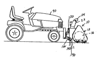
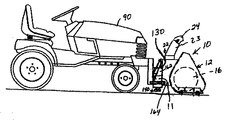
図1は、エリアから雪を取り除くための、本発明の観点による機械10を示す。機械10は噴射式除雪機を含むことができる。上で議論されたように、語句「エリア」は、少なくとも1つの回転するオーガあるいは羽根車を有する機械により、吹雪の後きれいにされる、自動車道およびある種の車道、駐車場や路地だけでなく、歩道や小道、階段、テラスやデッキのような他の知られた歩行者用の通路を指す。下で議論されるように、除雪機械10は、エリアから雪を除くために、自己推進式あるいは別に駆動される乗物に付属の従来の噴射式除雪機と同じように作動する。 除雪機械10は、筐体20、モータ40および通路に表面処理材料を配するための応用システム100を含んでいる。
FIG. 1 shows a
除雪機械の筐体20は、図中に示されるように、従来の噴射式除雪機のそれに形状と構造において類似している。 図面は、説明のために様々な噴射式除雪機を示す。 他のタイプの噴射式除雪機あるいは除雪機械が、この発明と共に使用されてもよいことが理解されるに違いない。 筐体20は、これを通って取り除かれる雪が副筐体11に入ってくる開口部12を有する前部の副筐体11を含む。図2に示されるように、開口部12は、機械10のパスを横切って、対向する側壁13、14の間に伸びている。 副筐体11は、開口部12に入る雪に接触しこれを切る、少なくとも1つの従来の回転可能部材16を有する。回転可能部材16はまた、雪を副筐体11内に移動させる。 図2に示される実施例では、よく知られているように、回転可能な部材16は、副筐体11内の雪と接触しこれを切る複数の刃を有する少なくとも1つのオーガ17を含む。図1に示される別の実施例では、回転可能部材16は、開口部12に入る雪と接触し雪を移動させるための多くの刃あるいはブラシ部材を有する少なくとも1の羽根車16´を含む。一方の実施例では、よく知られているように、副筐体11の側壁13、14に各々回転可能にマウントされた他端を有するシャフト18によって、回転可能部材16はしっかりと支持され作動する。 シャフトは、シャフトの端で少なくとも1つの鎖歯車あるいはプーリに連結されたチェーンか駆動ベルトを駆動するモータ40を用いて、任意の既知の方法で、駆動可能である。副筐体11は、雪が開口部12に入り、回転部材16によって操作され、副筐体11から捨てられることを可能にする任意の従来の形状とすることが可能である。
The
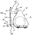
1つの実施例では、除雪機械10は、図1に示されるように、従来のやり方で筐体20上に回転可能にマウントされた排雪シュート23を含む、従来の関節のある雪排出管アセンブリ22を含む2段式除雪機械である。 雪排出管アセンブリ22は、副筐体11内に位置した、回転ファン19上に並べられる。知られているように、ファン19は、雪が副筐体11内で受け取られ、除雪機械10から捨てられるように排雪シュート23を通して回転部材16によって操作されるようにされる。 排雪シュート23は、雪がファン19によって投げられる通路を変えるための回転端部24を含むことができる。
In one embodiment, the
図1に示される別の実施例では、除雪機械10は、開口部12を通して副筐体11に入ってき、除雪機械10から捨てる雪を集める、回転部材16´(羽根車)を含む1段式機械である。知られているように、1段除雪機械では、羽根車16´は、開口部12に入る雪を操作し排雪シュート23から雪を投げるために用いられる、動力付きの部材である。 羽根車16´は、側壁13,14へジャーナルされ、また知られているダイレクトドライブ機構によってモータ40に接続されるかもしれない。
In another embodiment shown in FIG. 1, the
上記の実施例のどれでも、除雪機械10は、図中で示されるような筐体20にマウントされる表面処理応用システム100を含むかもしれない。応用システム100は、様々なテクニック(それらのうちのいくつかは図によって描かれる)を使用して除雪機械にマウントされ、あるいは様々な既知の方法を用いて、従来の除雪機械に後で取り付けられるかもしれないことが理解されるに違いない。
In any of the above embodiments, the
運転中、表面処理応用システム100は、防氷されるべきエリアに、少なくとも1つの表面処理材料200を適用する。 除雪機械10が通った後、氷または雪がそのエリア上に形成あるい再形成されることを防ぐために、この応用システム100はそのエリアに処理材料200を適用する。
In operation, the surface
表面処理材料200は、液体、霧吹き可能な粉末、粒状物、あるいは2以上の混合物であり得る。一実施例では、表面処理材料200は液体として塩化マグネシウムを含んでいるかもしれない。 表面処理材料200は、また米国特許番号5,302,307に開示されたものを含むことができる。それは参照することによってこれに組込まれる。表面処理応用システム100と共に使用されるかもしれない他の処理材料は、例えばCargill社のCargill Saltにより商品名Hydro-Melt.TMで売られたもののような、従来散布される液体防氷剤および(または)凍結防止材料を含む。Hydro-MeltTMは、岩塩より低い温度で氷結することを防ぐ腐食抑制剤を有する液体の防氷剤/凍結防止剤である。Hydro-MeltTMの防氷剤はまた、氷が表面で形成されるのを防ぐ(凍結防止)ために、予め濡らされたエイジェントとして機能する。例えば液体の塩化カルシウム、液体のナトリウムブライン、液体の酢酸カリウム、液体のギ酸カリウムあるいはメタノール、あるいは上記材料のいずれかの組み合わせのような、他の液体の防氷剤および(または)凍結防止剤も使用することができる。
The
別の実施例では、表面処理材料は粒状の処理材料を含んでいてよい。「粒状の」処理材料は、少なくとも固体の微粒子材料、噴霧可能な粉末、あるいは固体の微粒子と液体の混合物を含んでいてよい。図11を参照して、表面処理材料700は、岩塩のような従来の道路処理塩を含む。 処理材料700はまた、商品名CG90(R)オリジナルや商品名CG90(R)サーフェスセーバでCargill社のCargill Saltにより売られているもののような、粒状防氷剤および(または)凍結防止材料を含んでいてもよい。道路表面に沿って、腐食やはがれに対する優れた保護を有ししかも防氷効果を上げるために、これらの処理材料は、モノナトリウム・リン酸エステル単独、あるいはフレーク塩化マグネシウムと混合された岩塩を含む。他の表面処理材料としては、例えば商品名Clear Lane(TM)の名の下にCargill Saltにより売られているもののような、予め濡らされた防氷剤および(または)、予め濡らされた防氷液を含む。この予め濡らされた処理材料は、所定エリアに必要な塩の総量を減らすと共に、ユーザの装置に対する腐食保護のため、糖みつと液体の塩化マグネシウムとを混ぜたじ岩塩を含む。多くの他の粒状防氷剤および(または)凍結防止剤は、処理材料700として用いられてもよい。システム100に適用される処理材料は、他の化学薬品がそれが通常働くより低温で、意図した目的のために働くことを可能にするために、他の化学薬品と組み合わせて前述の防氷剤/凍結防止液体あるいは固体材料のうちのいずれかを含んでいてもよい。
In another embodiment, the surface treatment material may include a particulate treatment material. A "granular" treatment material may include at least a solid particulate material, a sprayable powder, or a mixture of solid particulate and liquid. Referring to FIG. 11, the
図1-3に示されるように、1つの実施例では、表面処理応用システム100は、雪が取り除かれたエリアに表面処理材料を適用する、材料分配システム110を含む。描かれているように、材料分配システム110は、筐体20の後方に位置することができる。最初の実施例では、図1中に1つ以上に示されるように、垂直の側壁116、それは材料を分配するシステムであるが、あるいは筐体20の垂直壁117は後方部を永久的にしっかりと支持する。第2の実施例では、図2及び図8に示されるように、材料分配システム110は、筐体20の底壁118に移動可能にあるいは永久的に支持される。第3の実施例では、材料分配システム110は、後部垂直壁117と底壁118の間に伸びる角度のある壁に、着脱可能にあるいは永久的に支持される。上述の位置のうちのどれでも、材料分配システム110は、その各々の壁117-118の外表面にマウントされるか、あるいはその各々の壁の開口部の各々数を通して伸びることができる。他の代替実施例中で、材料分配システム110は、筐体のまわりの異なる位置に置かれる複数のサブシステムを含むことができる。 例えば、1つのサブシステムは底壁118に支持されてもよく、別のサブシステムは後部垂直壁117に支持することもできる。 材料分配システムの実例のすべては、口12の後ろにある筐体20上で他の位置に、着脱可能にあるいは永久的に置かれたか、マウントされたか、後で組み込まれたと理解されるべきである。
As shown in FIGS. 1-3, in one embodiment, the surface
図面中に示されるように、材料分配システムは、除雪機械10によってきれいにされたエリアに、固体または液体の処理材料200を適用するために、1つ以上の部材を含むことができる。液体の処理材料200を用いる1つの実施例では、材料分配システム110は、処理材料用の少なくとも1つの噴霧機構140を含んでいてよい。図5および図6中に示される実施例では、噴霧機構140は、その噴霧領域が除雪の後ろの全エリアをカバーするが、除雪機械10や除雪機械10を押す乗物や操作者の足に噴霧しないような、噴霧ジェットのような単一のスプレイノズル142を含む。ノズル142は、約0.1〜1.0ガロン/分(gpm)間の噴霧速度で噴霧することが可能な、既に知られているノズルであり得る。実際の範囲では、ノズルは約0.2- 0.8 gpmの間の噴霧速度で供給できた。適切なノズルとしては、StreamjetTMから製品コードSJ3-03-VPかSJ3-08-VPの下に、利用可能に出されている3本のオリフィス・ノズルを含む。これらのノズルは、約0.24と0.35 gpmの間の流速で、あるいは0.56〜0.94 gpmの間の流速で各々20から60プサイで、供給できる。5本のオリフィス・ノズルを含んで、3本を越えるオリフィスを含むノズルも、使用することができる。 複数のオリフィス・ノズルは、特別の圧力で所定流速のオリフィスのうちの1つが、そのエリアに処理材料を配するために扱われるエリアの方へ指示されるまで回転することが適当な単一のノズルであってよい。
As shown in the figures, the material distribution system can include one or more components for applying solid or
語句「噴霧領域」は、流体が所定のノズルから噴霧される時、カバーされる表面エリアの大きさに関する。理解されるように、ノズル142のための噴霧領域の大きさは、除雪機械10によって取られた通路の大きさに応じて変わるだろう。ノズル142やここで議論された他のスプレーノズルの噴霧領域の大きさは、知られている各々のノズルの噴霧の穴の大きさを調整するか、処理材料200が各々のノズルに適用される処理の圧力を調整することにより、変えることができる。実例となる噴霧領域は、操作者の前で除雪機械10の後ろに伸びる領域、少なくとも実質的に側壁13,14の間、あるいは側壁13,14の一方の横に約1インチから約12インチ間の点を含んでいる。
The phrase "spray area" relates to the size of the surface area covered when fluid is sprayed from a given nozzle. As will be appreciated, the size of the spray area for the
図3および図4中に示される別の実施例では、噴霧機構140は、筐体20の内部か外部に直接支持されるか、上述のいずれかの場所で、筐体20に接続される噴霧バー145に沿って離間して支持される多数の噴霧ノズル144を含む。これらのノズルは、約0.1gpmから1.0gpmの流速を提供する上述のノズルのうちのいずれかを含むことができる。しかしながら、他の従来の噴霧ノズルを使用することもできる。ノズル144の各々は、筐体20に沿って隣接したノズル144から一定間隔で配置される。隣接したノズル144も、噴霧バー145に沿って互いに一定間隔離して配置される。噴霧バー145あるいは筐体20のいずれかの上の隣接したノズル144間の間隔は、各ノズルの噴霧領域、扱われるエリアおよび(または)除雪機械10によってきれいにされた通路の大きさに依存して変わるだろう。例えば、4つのノズル144が、24インチの広い除雪機械10(側壁13、14の間で)に沿って一定間隔で配置されるなら、中央で互いにノズル144を6インチ間隔で置くことができるかもしれないし、また最も外側のノズル144は側壁13,14から約2インチ内部に間隔をおいて置かれるだろう。
In another embodiment shown in FIGS. 3 and 4, the
図1-3中に示されるように、表面処理応用システム100はさらに、入っている処理材料200が材料分配システム110に流れることを可能にする筐体20のどんな場所でも置くことができる容器130を含む。1つの実施例では、図1に示されるように、容器130は、筐体20の後部の垂直壁117に、ハンドルに近い位置で支持されてもよい。しかしながら、処理材料200を材料分配システム110に配される他の位置に置くこともできる。
As shown in FIGS. 1-3, the surface
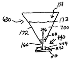
容器130は、処理材料200を保持するだけの容量を有する大きさとすることができる。除雪機械10の全体の大きさが変わると、容器130の容量を変えることが可能である。例えば、18インチの広い開口部12を有する除雪機械10の容器130は、28インチの広い開口部12を有する除雪機械10の容器と同じか小さいことがあり得る。1実施例では、容器は、処理材料200の約1〜5ガロンを保持する容量を有することができる。しかしながら、容器130の容量は、顧客の必要、除雪機械10の大きさ、除雪機械10の後ろに置かれるエリアに依存して使用することができるかもしれない。容器130は、品質を下げることなく、処理材料200を保持することが可能な既知の材料から作ることができる。実例となる実施例では、容器130は、プラスチックかポリマー、あるいは他の適切な材料を用いて作ってよい。
The
図8および図9中に示されるように、容器130はさらに、入れられる処理材料200に熱を加えるためのシステム480を含むことができる。 加熱装置480は、華氏でおよそ20〜220度の温度範囲で処理材料200を維持することができた。しかしながら、各処理材料200の温度範囲は処理材料のタイプに依存して変わるかもしれない。 例えば、メタノールに基づいた処理材料用の温度範囲は、華氏でおよそ20〜80度の間にあるかもしれない。システム480によって達成される温度は処理材料の揮発性にも依存する。
As shown in FIGS. 8 and 9, the
図8中に示されるように、容器130は、所定温度で処理材料200を維持するために操作者によって選択的に励起することが可能な加熱コイルのような加熱部材482を含むことができる。上述のように、温度は、いくつかの材料はより高い温度で他のものより揮発するかもしれないので用いられる処理材料に依存することができる。 図9中に示される別の実施例では、入れられた処理材料200に熱を加えるためのシステム480は、容器130の開口部488への第1の端で、また機械10の排気マニホルドかマフラのある部分を越えて第2の端489で支持される導管486を含むことができる。この実施例では、所定温度で処理材料を維持するために、機械10のエンジンからの熱いガス排気の少なくとも1部が、容器130に向けられるかもしれない。あるいは、導管486は、容器130の側壁中の凹部を通じて伸び、容器130の壁を介して容器130内の処理材料200に熱を伝えるかもしれない。この実施例では、容器130および導管486の少なくとも1部が、熱伝導性を有する材料から作られるかもしれない。少なくとも1つの実施例では、この熱伝導性を有する材料は金属であり得る。 さらに、容器は電気的にあるいは高周波加熱によって加熱されてもよい。
As shown in FIG. 8, the
あるいは、上述の容器加熱装置に加えて、ノズルへの導管および(または)ノズルそれら自体は、つまりを防ぎしかも(または)、適用される処理材料の熱溶融能力を増加させるために、加熱されるかもしれない。さらに、除雪機械10は、機械が雪を取り除く表面を熱するためのシステムを含むことができる。例えば、除雪機械10は、処理材料が適用されるエリアの表面を予め熱することにより、雪/氷の融解を助けるために、華氏約100〜300度の間の温度に上げられた放射加熱の素子か気流を含むことができる。勿論、この範囲の外側の温度を用いてもよい。ここに含まれる加熱材料の例では、地面上の雪および/氷の温度の上に配される材料(液体、固体、粉末、ゲルおよびその他同種のもの)を積極的に熱することは有益かもしれない。この表面加熱はまた、防氷剤および(または)凍結防止処理材料を容易に受け入れるかもしれない表面を増加させその活性化時間を増加させることにより、処理材料の防氷および(または)凍結防止の能力を改善するかもしれない。
Alternatively, in addition to the vessel heating devices described above, the conduits to the nozzles and / or the nozzles themselves may be heated to prevent clogging and / or increase the thermal melting capacity of the applied processing material. Maybe. Additionally,
上述の実施例のうちのどれにおいても、プラスチック、ポリマーあるいは複合材料から作られた管のような流体の流量管150は、図1および図3に示すように、容器130とそれぞれに処理材料200を配する噴霧ノズルとの間に伸びている。 流通管150は、容器130の第1の端と、ノズルか噴霧バー145への第2の端で支持することができる。
In any of the embodiments described above, a
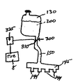
図3中に示されるように、処理応用システム100はまた、扱われるエリアに適用される処理材料200の量を制御するためのシステム300を含む。最初の実施例では、制御システム300は、チェックバルブ310が開いているとき、容器130から材料分配システム110のノズルまで流体が流れることを可能にするために、電気的あるいは機械的に操作することが可能な、一方向性のチェックバルブ310を含んでいるかもしれない。バルブ310は、フラッパー・バルブやカモノハシ・バルブを含むがこれらに限定されない、任意の知られた一方向性のチェックバルブであり得る。このバルブ310は、流通管150に沿ったどの点にでも位置させることが可能である。1実施例では、駆動系が解放されるとき、除雪機械10の駆動系が作動し閉じられる場合は常に、自動的に開くように、バルブ310の開口部をセットすることが可能である。 駆動系が作動している間、操作者がバルブ310を閉じることを可能にする補充手動スイッチをそれは含むことができる。さらに加えてあるいは代替的に、除雪機械10は、容器300からの処理材料200の流れる量を制御するために、スイッチ318が閉じられるとき操作者が手動でバルブ310を開き、スイッチ318が開かれているときバルブ310を閉じることを可能にするスイッチ318を含んでいてもよい。 スイッチ318は、除雪機械10の駆動系の操作とは独立させることができる。
As shown in FIG. 3, the
図7中に示される別の実施例では、除雪機械10の後部タイヤ8が動く表面の状態を決定し、バルブ310の開閉を制御するためにセンサ325が用いられてもよい。例えば、センサ325は、副筐体11がたった今通過した表面でタイヤ8のどちらがスリップしているか検知し、検知されたスリップに応じてバルブ310を開かせることができる。ホイールがスリップしていることを検知する、全輪駆動車と共に使用されるもののような従来のセンサを、タイヤ8が表面を把持していないときおよび処理材料200を適用する必要があるときを検知するために、除雪機械10上に置くことができる。あるいは、センサ325は、副筐体が通過した表面上の雪、半解け雪および(または)氷の形成の結果として、少なくともタイヤ8の一方が持ち上げられたことを判断するレベル検出器でありえる。「タイヤ」は、ここで使用されるように、トラックや、地上の機械を移動させるために使われる他の地面把持部材含む総括的な語句である。レベル検出器325は、きれいにされたエリア上の雪、および(または)氷の積み重ねにより、他のタイヤ8や前部開口部12に対する角でタイヤ8の少なくとも1つがそれているときを検知することが可能である。センサ325が作動する角度は、約5〜10度程度あるいはそれ以上の所定の角度であり得る。所定角度に到達したとレベル検出器が判断すると、バルブ310が開き、ノズルを介してその表面に処理材料が噴霧されるだろう。
In another embodiment, shown in FIG. 7, a
他の代替実施例では、機械10は、バルブ310を開き、ノズルに接続され所定の時間間隔で処理材料200をポンプに噴霧させる、既知の論理制御システムを含む。これらの時間間隔は、各ノズルの噴霧領域の大きさと直接、関係させることができる。例えば、各ノズルの噴霧領域が大きいほど、各噴霧の時間間隔は大きくなる。 各噴霧の時間間隔は、約1秒から約10秒までであり得る。1実施例では、各噴霧の時間間隔が約2〜6秒の間にある。しかしながら、上述のように、実際の時間間隔は、各ノズルの噴霧領域と噴霧時に各ノズルが作動する時間に応じて変わるだろう。あるいは、既に議論されたように、ホイールまたはタイヤ8が移動している間、ノズルは連続的に噴霧することができた。
In another alternative embodiment, the
線150内に圧力を生成するために、図3中に示されるように、小さなポンプ370を容器130内に位置させることができる。 約1/200HPから約1/100HPの範囲の馬力を有する、従来の液体の水中ポンプを用いることができるかもしれない。 これらのポンプは約0.3〜3.0gpmの間の流速を提供する。さらに、処理されるエリア上に処理材料が噴霧される圧力および流速を増加させるために、小さなポンプも噴霧ノズル内に位置させることができる。上で議論した、流速を与える、従来の動力による噴霧ノズルを使用することができる。1つ以上のポンプの強さを制御することにより、廃物が少なくなるように、ノズルの噴霧領域および処理材料の流速を制御することができる。別の実施例では、容器130の外に空気ポンプのような既知のポンプ(図示せず)を置くことができるかもしれない。 起動された時、容器130内の圧力がバルブ310の抵抗より大きく、液体の処理材料200が導管150を通り、空気ポンプによって作られた圧力の下のノズルにかけられるように、空気ポンプは容器130内の圧力を増加させるだろう。
To generate pressure in
図10中に示された別の実施例では、容器130内の流体圧力は、内部に位置した仕切板526に接続され手動で操作されるハンドル525を有する手押ポンプ520を用いて増加させられる場合がある。一実施例では、容器130の一部としてこのポンプを形成することができるかもしれない。別の実施例では、液体導入開口部のような、容器130への開口部を囲む、協同するねじあるいは他の既知のロックシステムにそれを付けることにより、容器130へポンプ520を支持することができるかもしれない。運転中、容器130へ空気を導入し、かつそれにより容器130内の気圧を増加させるために、操作者はハンドル525およびポンプ520の仕切板526を往復運動させるだろう。所望量の流体圧力が容器130内にできるまで、処理材料200の十分な流速を与えるために、ポンプをこぐことは継続する。 容器内に生じた圧力および生じる流速は、扱われるエリア上に噴霧するためのノズルを通って処理材料200を流れさせるだろう。 生じた圧力は、約0.2〜1.0の間の流速を生ぜしめるために、約20〜約100プサイの大きさを有することができた。
In another embodiment, shown in FIG. 10, the fluid pressure in the
追加の実施例では、エンジン・マニホルドからの排気で、圧力が容器310内で増加し、圧力レベルが増加することがある。 この実施例では、エンジン・マニホルドからの排気は、容器310内の圧力がエンジンの動作中に所望レベルに増加するように、容器310あるいは、開口部316を通って容器310の上に位置したブラダー315(図4)に向けられるだろう。容器310またはブラダー315は、容器310内の圧力がチェックバルブ310に打ち勝つ必要のあるレベルあるいはその上であると、あるいは特定の噴霧領域および流速を達成するために必要とされる所望量を与えるために必要とされるレベルにあると、排出する安全バルブを含むことができる。
In additional embodiments, the exhaust from the engine manifold may cause the pressure to increase in the
更に他の実施例では、重力はノズルに流体を配するために使用することができる。この実施例では、ノズルに関連した上述のポンプは、所定の流速でしかも所定噴霧領域中で流体を分配するだろう。さらに、ノズルは液体ポンプの制約を受けないかもしれない。そのような実施例では、重力はノズルから扱われる表面に処理材料を伝えるだろう。 In yet another embodiment, gravity can be used to distribute fluid to the nozzle. In this embodiment, the above-described pump associated with the nozzle will distribute fluid at a predetermined flow rate and in a predetermined spray area. Further, the nozzle may not be restricted by the liquid pump. In such an embodiment, gravity will transfer the treated material from the nozzle to the surface being handled.
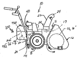
図11-19中に示されるように、表面処理応用システムの他の実施例では、雪が取り除かれたエリアに粒状の表面処理材料を適用する。図11中に示されるように、表面処理応用システム600は、扱われるエリアに粒状の表面処理材料700を適用する、材料分配システム610を含む。 処理材料700が供給されるエリアの大きさは、除雪機械10によって得られた通路の大きさに応じて変わるだろう。 図12を参照して、実例となるエリアは、操作者の前で、除雪機械10の後ろに伸びる領域を含んでおり、少なくとも実質的に側壁13,14の間で、あるいは側壁13,14の一方の横約12インチまでの約1インチの間の点を含む。
As shown in FIGS. 11-19, in another embodiment of the surface treatment application system, a granular surface treatment material is applied to the area from which snow has been removed. As shown in FIG. 11, the surface treatment application system 600 includes a
図11および図12中に示されるように、材料分配システム610は筐体20の後ろに位置することができる。上記実施例と同様に、材料分配システム610は、筐体20の後部垂直壁117、あるいは垂直側壁116の1つ以上へ支持される。 あるいは、材料分配システム610は筐体20内に支持される。上記位置のうちのどれでも、材料分配システム610は、筐体20に着脱可能にあるいは永久に支持されるか後で付けることができる。
As shown in FIGS. 11 and 12, the
代替実施例では、材料分配システム610は、筐体20の周囲の異なる場所に位置した、多種多様な分配システム610を含むことができる。例えば、垂直壁117の第1の後部側端部119上で1つのサブシステムを支持することができるかもしれないし、垂直の壁117の他の後部側端部119上で別のサブシステムを支持することができるかもしれない。除雪機械10によってきれいにされたエリア一帯に処理材料700をばら撒かれることをできるように、筐体20上のどこにでも1つ以上の材料分配システム610を置いてもよいことは明らかである。
In alternative embodiments, the
材料分配システム610は、除雪機械10によって雪が取り除かれたエリアに処理材料700を撒く、1つ以上のばら撒き部材640を含むことができる。1つの実施例では、材料分配システム610は、処理材料700を受け取り保持するために開口内部131を有するホッパ630を含む。 材料分配システム610はまた、扱われるエリア一帯に処理材料700をばら撒くために、ホッパ630に効果的に関連付けられた、少なくとも1つのばら撒き部材240を含む。
The
ホッパ630は、処理材料700を保持するために、容量に応じて大きさを決めることができる。ホッパ630の容量は、除雪機械10の全体の大きさが変わると、変えることができる。例えば、18インチの広い開口部12を有する除雪機械10のホッパ630は、32インチの広い開口部12を有する除雪機械10のホッパ630と同じか小さくすることができるかもしれない。実施例では、ホッパ630は、処理材料700を約1ポンドから約10ポンドを保持する容量を有することができる。1実施例では、ホッパ630は2〜5ポンドの処理材料700を運ぶことが可能である。しかしながら、ホッパ630は、顧客の必要、顧客の必要、除雪機械10の大きさ、および除雪機械10の後ろで処理されるエリアに応じて、処理材料700の保持量を大きくしたり小さくしたりすることができる。ホッパ630は、品質を下げずに、処理材料700を保持できる既知の材料から作ることができる。 例えば、ホッパ630は、金属、プラスチック、ポリマーあるいは他の適切な材料から作られるかもしれない。
The
ホッパ630は、ばら撒き部材640に粒状材料を向けるすべての既知の形状を有することができる。さらに、ホッパ630は各々異なる形状と共に、複数のセクションを含めることができる。例えば、図13中に示されるように、ホッパ630は、1対の実質的に垂直の上部側壁162を有する実質的に長方形の上部部材161を含めることができる。ホッパ630はまた、ホッパ630の実質的にV字形の部分を形成する、より低い側壁164を実質的に集める1対を有する、より低い三角形の部分163を含めることができる。ほっぱ630のより低いV字形の部分163は、処理材料700がホッパ630から配されると、2つの側壁164の頂点の方向にホッパ630内の処理材料700を向ける。図14中に示された代替実施例では、処理材料700を保持するために実質的にV字形の容器を形成するために、ホッパ630の側壁172はそれらの上部の表面から互いの方へ集中する。しかしながら、上で議論されたように、ホッパ630は上述の形状だけに限定されない。本当はホッパは、ばら撒き部材640に処理材料700を配するために、ホッパ630の最も低い点にある吐出口166の方向に処理材料を向けるすべての既知の形状を有することが可能である。
The
図13中に示されるように、ばら撒き部材640は、ホッパ630の外側で吐出口166に近くで隣接する場所に位置する。ばら撒き部材640は、上部表面242と多くの一定間隔で配置されたリブ244を備えた回転可能なプレート240を含んでいる。プレート240のの回転軸246は、ホッパ630の高さと実質的に平行に延びるように、垂直方向に向けられる。プレート240は、吐出口166を出る任意の処理材料700を受け取るために吐出口166に合わせられる。図13および図14の中で示されるように、リブ244は、半径方向にプレート240の中央部から離れ、プレート240の上部の表面242から垂直に離れて延びている。さらに、リブ244は、扱われるエリアの所定部分を越えて処理材料700をばら撒くように、プレート240の回転運動と協働する。
As shown in FIG. 13, the spreading
図19中に示された代替実施例では、ばら撒き部材640は、吐出口166の内部表面に近似で隣接しているホッパ630内に少なくとも部分的に位置している。 ばら撒き部材640は、シリンダ260の縦軸と実質的に平行な方向にシリンダ260の長さに沿って、しかもシリンダ260の外部表面から半径方向に外へ伸びる多くのリブ263を有する回転可能なシリンダ260を含んでいるかもしれない。 各リブ263は、シリンダ260の周囲に沿って隣接したリブ263から、ある角度をなして置かれている。 リブは、所定エリア一帯に処理材料をばら撒くように、シリンダ260と協働する。 シリンダ260の回転軸は、除雪機械10の側壁13、14間の方向、あるいは除雪機械10の前部と後部の間の方向に伸びることができる。
In the alternative embodiment shown in FIG. 19, the distributing
上記実施例のいずれかでは、ばら撒き部材640は手動であるいは自動的に、あるいは両方で、回転することができる。 第1の実施例では、操作者が関連するクランクを回転させると、ばら撒き部材640は手動で回転する。 代替実施例では、動力が供給されたモータは、単一の所定回転速度で、あるいは複数のプリセットされた回転速度のうちの1つでばら撒き部材640を、自動的に回転する。図11および図18中に示されるように、モータ147は、ばら撒き部材640を回転させるために単に作動する専用モータである。そのような実施例では、モータ147は、除雪機械10のモータが作動しているか、除雪機械10が専用モータ147を選択的に起動し停止するためにスイッチを含むことができる場合は常に、作動するためにセットすることができる。モータ147は、使用されるモータのタイプに依存して、電池、電気あるいはガスで動力が供給されてよい。
In any of the above embodiments, the spreading
あるいは、ペアかギアか、プーリ、と協働するベルトは、除雪機械のモータ40の出力軸にばら撒き部材640を効果的に連結することができる。その結果、除雪機械10のモータ40が作動するとき、ばら撒き部材640は回転するだろう。クラッチかスイッチは、ばら撒き部材640の回転を選択的に活性化または非活性化することを含むことができる。 別の実施例で、エンジン40からの排気は、ばら撒き部材640に効果的に接続され、ばら撒き部材640をそれ自身の動きに応じて回転させる、羽根車のような、回転可能部材上を通すことができる。
Alternatively, a belt that cooperates with a pair or a gear or a pulley can effectively connect the distributing
上記実施例のうちのどれでも、処理材料700が、除雪機械10の後ろに清潔になったエリアをカバーするように回転するとき、ばら撒き部材640は処理材料700を分配する。ばら撒き部材640は、除雪機械10、乗物プシング90あるいは操作者の足の上に処理材料700をまくことは意図されていない。あるいは、防氷および(または)凍結防止の材料を分配するのを助けるために、ばら撒き部材640は、噴射式除雪機上での散布(ここで散布とは、地面に処理材料を向けることである)に処理材料700を向けることである。この転換された処理材料700は、ばら撒き部材640(あるいは液体かゲル・タイプ材料に関するノズル)が、詰まらせられるか無効になるようになるのを防ぐ利点を有するかもしれない。 処理材料700用の分配エリアの大きさは、除雪機械10が通過した後、そのエリアに残る氷および(または)半解け雪の量、除雪機械10の隣接した通路間の処理材料700のための望みのオーバラップ量、ばら撒き部材640が回転する速度、および(または)吐出口166の大きさ、に依存して変わるだろう。
In any of the above embodiments, when the
ホッパ630の吐出口166の大きさは、ホッパ630から放出された処理材料700の量を変えるために、調節することができる。 吐出口166の大きさが大きくなると、ホッパ630から放出される処理材料700の量は増加するだろう。同様に、吐出口166の大きさが小さくなると、放出される処理材料700の量は少なくなるだろう。1つのパネル168あるいは複数のパネル(図示せず)は、吐出口166の大きさを調節するために使用することができる。パネル168は、ケーブルの第1の端へ支持することができる。操作者が対応するダイヤルを回転させるとき、ケーブルの第2の端は、手動で制御され回転するプーリに支持することができる。ダイヤルが回転する方向に依存して、吐出口166の大きさは大きくなるか小さくなるだろう。あるいは、操作者によって提供されるデータに応じて、吐出口166の大きさを変えるために、論理回路を用いることが可能である。 例えば、吐出口166に関するパネル168の位置は、除雪機械10の操作者によって論理回路の制御装置に入力される流速に応じて、吐出口166の大きさを大きくしあるいは小さくするために、自動的に変えることができる。
The size of the
一実施例では、駆動系が解放されるとき、除雪機械10の駆動系が起動され閉じられる場合は常に、それが自動的に開くように、吐出しポート166の開口部をセットすることができる。駆動系が駆動されているとき、操作者が吐出口166を閉じることを可能にする補充手動スイッチをも含むことができるかもしれない。同様に、図18中に示されるように、除雪機械10は、除雪機械10が作動しないとき、操作者が手でパネル168を開き、パネル168を閉じることを可能にするスイッチ318を含むことができる。スイッチ318は、除雪機械10の駆動系の操作とは独立しているかもしれない。
In one embodiment, the opening of the
図17中に示されるように、そして図7に似て、センサ325は除雪機械10の後部タイヤ8が動く表面の状態を決定し、パネル168の開閉を制御するために用いることができる。上述のように、センサ325は、副筐体11がたった今通過した表面の上でタイヤ8のどちらがスリップしているかを判断し、検知したスリップに応じてモータ327を作動させ順番にパネル168を開かせることができる。操作者は、検知された状態に応じて、吐出口166の大きさをプリセットするか、あるいはセンサ325により制御することができる。上記の実施例と同様に、センサ325は、パネル168の開閉を制御してばら撒き部材640に配される処理材料を制御する役目をするレベル検出器を含む、任意の従来のセンサであってよい。
As shown in FIG. 17 and similar to FIG. 7, the
図17中に示されるように、ホッパ630は、オーガのように、処理材料700を撹拌するために、ホッパ630の内室131内に伸びる回転可能な部材180を含むことができる。回転する部材180の外表面は、処理材料700が吐出口166に向けられるように、入れられた処理材料700を取って撹拌するための、縦方向に伸びる刃あるいは円形状の刃のような、多くの部材182を含むことができる。
As shown in FIG. 17, the
回転可能な部材180は、クランクによって手動で回転され、部材180にリンクされたモータ(図示せず)が起動されるとき自動的に回転することができる。モータは、除雪機械10のモータ40とは独立の専用モータであり得る。あるいは、回転可能部材180は、ベルト、チェーンあるいは、除雪機械10のモータ40の出力軸に効果的に付けられた他の既知の駆動系によって回転することができる。 撹拌部材180が回転するとき、処理材料700を分離しておき、開口部166の方向にそれを移動させるだろう。
The
撹拌部材180は、入れられた処理材料700を熱するための加熱コイルを含むことができる。あるいは、撹拌部材180は、処理材料700を暖めるためにモータから排気がホッパ630の内部に導かれる開口部を含むことができる。さらに、ホッパ630内の処理材料700は電気的にあるいは高周波加熱を用いて熱せられるかもしれない。上記実施例のうちのどれでも、処理材料700は、その効率を増加させる任意の温度で維持することが可能である。例えば、処理材料は、ホッパ13内に含まれる処理材料に依存して、およそ華氏20〜700度の間の温度で保持することができる。ホッパ630内に達成された温度は、用いられる特定の処理材料700およびその処理材料700の揮発性に依存する。例えば、より揮発性の高い処理材料700の温度範囲は、およそ華氏20〜90度の間にあるかもしれない。あるいは、いくつかの処理材料は、もし華氏90度あるいはそれを越える温度で維持されれば、最も良く働くかもしれない。
さらに、除雪機械10は、機械が雪を取り除く表面を熱するためにシステムを含むことができる。例えば、除雪機械10は、処理材料が適用されるエリアの表面を予め熱することにより、雪か氷の融解を助けるために、およそ華氏300〜600度の温度範囲に上げられた放射加熱エレメントか気流を含むことができた。 表面のこの加熱はまた、防氷剤および(または)凍結防止処理材料による処理を容易に受け入れその活性化時間を増加させる表面を作ることにより、処理材料700の防氷および(または)凍結防止の能力を改善するかもしれない。
Further,
更に他の実施例では、防氷するかまたは凍結防止の材料、材料を流通させる機構、および材料流通機構を制御する制御システムを保持する容器か小缶も、噴射式除雪機とは別に売られてもよい。 例えば、防氷または凍結防止のシステムは、既存の噴射式除雪機の後付けのものとして売られるかもしれない。従って、購入者は、防氷または凍結防止のシステムを備えた噴射式除雪機を購入するとき組み込まれるオプション、および防氷または凍結防止のシステムを別々に購入し、噴射式除雪機にそれを付けるオプションとして供給されるかもしれない。 既に噴射式除雪機を購入していた各個人や団体にとって、防氷または凍結防止のシステムだけを得ることは、噴射式除雪機および防氷または凍結防止のシステムの組み合せを購入するより、コスト効率が良いかもしれない。 In yet another embodiment, containers or canisters holding deicing or deicing material, a mechanism for distributing the material, and a control system for controlling the material distribution mechanism are also sold separately from the blast snowplow. May be. For example, an anti-icing or anti-icing system may be sold as a retrofit to existing snow blowers. Accordingly, the purchaser purchases separately the ice-protection or anti-freeze system and attaches it to the spray-type snow plow, with the option to be incorporated when purchasing the snow-plow or snow-prevention system. May be supplied as an option. For each individual or organization that has already purchased a snow blower, obtaining only an anti-icing or anti-icing system is more cost-effective than purchasing a combination of an injection snow-blowing and anti-icing or anti-icing system. Might be better.
ここでは実施例に適用するように本発明の基本的な新規の機構を図示し説明し指摘したが、それは、図示されたデバイスの形状詳細の様々な記載省略および置き換えや変化、その動作は、ここで広く開示されているように本発明の制振と視点から離れずに、当業者により作られることが理解されるだろう。 例えば、処理材料容器130はまた、排雪シュート23および(または)回転可能な部材16に、防氷剤および(または)凍結防止材料を供給する導管を含むことができる。 さらに、上述された表面処理応用システムの実施例は液体と固体の表面処理材料を用いるシステムを提供するために組み合わせられるかもしれない。さらに、上述の実施例は当業者により従来の除雪機械10に後で付けられあるいは適応されることが理解される。
While the basic novel features of the present invention have been illustrated and described herein as applied to embodiments, it will be understood that various omissions and substitutions or changes in the illustrated device details may be made, It will be appreciated that the present invention can be made by those skilled in the art without departing from the damping and perspective of the present invention as widely disclosed herein. For example, the
Claims (66)
雪が除雪機械にこれを経由して入る前方の開口部を含む筐体;
前記筐体の内部からの雪を掴み除去するための、前期筐体内に位置する少なくとも1つの回転部材; と、
エリア一帯に防氷および(または)凍結防止の処理材料を配する筐体に連結された処理材料分配システムを含む表面処理応用システム。 Snow removal machines with:
An enclosure containing a front opening through which snow enters the snow removal machine;
At least one rotating member located within the housing for grabbing and removing snow from inside the housing;
A surface treatment application system including a treatment material distribution system coupled to a housing for disposing anti-icing and / or anti-freezing treatment materials throughout the area.
前記筐体内に受け取った雪を掴む少なくとも1つの回転部材と、そのエリアに処理部材を適用するために前記筐体に関連付けられた表面処理材料応用システムとを含む筐体。 Machine for removing snow from the area, having:
A housing including at least one rotating member for gripping snow received in the housing and a surface treatment material application system associated with the housing to apply a processing member to the area.
材料を保持するための保持エリア;
材料を分散させる分散システム;そして、
噴射式除雪機にシステムを付けるためのアタッチメント機構。 A system for distributing anti-icing and / or anti-icing materials, including:
Holding area for holding material;
A dispersion system for dispersing the material; and
Attachment mechanism for attaching the system to the snow blower.
Applications Claiming Priority (1)
| Application Number | Priority Date | Filing Date | Title |
|---|---|---|---|
| US10/404,070 US7137214B2 (en) | 2003-04-02 | 2003-04-02 | Snow removal machine with system for applying a surface treatment material |
Publications (2)
| Publication Number | Publication Date |
|---|---|
| JP2004308418A true JP2004308418A (en) | 2004-11-04 |
| JP2004308418A5 JP2004308418A5 (en) | 2007-05-10 |
Family
ID=32850582
Family Applications (1)
| Application Number | Title | Priority Date | Filing Date |
|---|---|---|---|
| JP2004106916A Pending JP2004308418A (en) | 2003-04-02 | 2004-03-31 | Snow removing machine provided with system using surface treatment material |
Country Status (6)
| Country | Link |
|---|---|
| US (2) | US7137214B2 (en) |
| EP (1) | EP1464759B1 (en) |
| JP (1) | JP2004308418A (en) |
| AT (1) | ATE426065T1 (en) |
| CA (1) | CA2461502A1 (en) |
| DE (1) | DE602004020009D1 (en) |
Cited By (4)
| Publication number | Priority date | Publication date | Assignee | Title |
|---|---|---|---|---|
| JP2008308833A (en) * | 2007-06-12 | 2008-12-25 | Nippon Expressway Research Institute Co Ltd | Method and equipment for removing snow ice on road |
| JP2014521854A (en) * | 2011-08-12 | 2014-08-28 | クァンジュ ナンーグ オフィス | Snow removal equipment for vehicles |
| KR200478349Y1 (en) * | 2015-03-25 | 2015-09-21 | 강홍구 | Snowplow cart |
| JP2022034512A (en) * | 2020-08-18 | 2022-03-03 | 日本特殊車輌サービス株式会社 | Snow melting vehicle |
Families Citing this family (26)
| Publication number | Priority date | Publication date | Assignee | Title |
|---|---|---|---|---|
| US7137214B2 (en) * | 2003-04-02 | 2006-11-21 | Cargill, Inc. | Snow removal machine with system for applying a surface treatment material |
| DE202005017883U1 (en) | 2005-11-16 | 2006-01-05 | Julius Tielbürger GmbH & Co. KG | Hand-guided landscape care device |
| US20070244605A1 (en) * | 2006-04-12 | 2007-10-18 | Mark Hopkins | Monitoring devices for use with ground treatment equipment |
| DE202006016981U1 (en) * | 2006-11-07 | 2007-10-11 | Lau, Andrew Manson | Combination device for snowblowing, mowing, scarifying or ground hoeing |
| US20080189990A1 (en) * | 2007-02-09 | 2008-08-14 | Luhtanen James L | Guide disc attachment for snow blower housing |
| US20080263906A1 (en) * | 2007-04-25 | 2008-10-30 | Jiangsu Golden Harbour Enterprise Ltd. | Snow thower |
| US7798432B2 (en) * | 2008-03-25 | 2010-09-21 | Envirotech Services, Inc. | Device for spraying anti-icing agents on transport surface |
| US8011120B1 (en) * | 2008-06-25 | 2011-09-06 | Hipple Samuel M | Material dispenser |
| KR100888029B1 (en) | 2008-09-30 | 2009-03-10 | 지수개발주식회사 | Sludge and Sewage Removal Device in Subway Platform Drain |
| US20100133365A1 (en) * | 2008-12-01 | 2010-06-03 | Master Manufacturing Llc | Spreader assembly with surface-clearing blower |
| KR101216943B1 (en) * | 2011-06-28 | 2012-12-28 | 주식회사 태강기업 | Liquid reservoir type snow removal machine which has multiple hot blades |
| WO2013173338A1 (en) * | 2012-05-15 | 2013-11-21 | Briggs & Stratton Corporation | Snow thrower and accessories |
| EP2639355A1 (en) * | 2012-03-15 | 2013-09-18 | Rapid Technic AG | Self-propelled work machine for removing snow and ice from pedestrian paths and roadways |
| US8584383B1 (en) * | 2012-09-21 | 2013-11-19 | Lanny E. Morse | Caster wheel assembly for a snowblower |
| US9096979B2 (en) | 2012-09-27 | 2015-08-04 | Louis Berkman Company | Software application that allows a user to utilize a mobile device to control frozen precipitation treatment systems |
| US9243376B2 (en) * | 2013-06-14 | 2016-01-26 | Pro-Tech Manufacturing And Distribution, Inc. | Surface compliant front-pivoting wear shoes for snow pusher |
| US20150053784A1 (en) * | 2013-08-22 | 2015-02-26 | H.Y.O., Inc | 6-Bit Hydraulic Manifold and Its Use in Spreading Salt |
| US9663910B2 (en) * | 2015-03-26 | 2017-05-30 | Emadeddin Zahri Muntasser | Flat roof snow thrower |
| CN104895003A (en) * | 2015-04-27 | 2015-09-09 | 北京首发公路养护工程有限公司 | Rolling brush device |
| SE540519C2 (en) * | 2015-08-26 | 2018-09-25 | Vaederstad Holding Ab | Procedure for the control of agricultural implements, as well as agricultural implements |
| US10472783B2 (en) | 2016-03-02 | 2019-11-12 | The Toro Company | Four wheel drive, skid steer snow vehicle with snow plow blade |
| CN107816008B (en) * | 2017-11-23 | 2024-01-05 | 国家电网公司 | Portable electric salt spreader |
| US11198982B2 (en) * | 2018-06-20 | 2021-12-14 | Michael R. Hoffmann | Skid wheel system |
| CN109736246B (en) * | 2019-03-05 | 2024-02-09 | 郭骏豪 | Snow-sweeping deicing device |
| IT202100000857A1 (en) * | 2021-01-19 | 2022-07-19 | Giletta Spa | METHOD AND SNOW BLADE FOR REMOVING SNOW FROM A ROAD SURFACE |
| US20230304242A1 (en) * | 2022-03-25 | 2023-09-28 | Douglas Dynamics, L.L.C. | Spreader or sprayer and control system therefore |
Citations (11)
| Publication number | Priority date | Publication date | Assignee | Title |
|---|---|---|---|---|
| JPS4864222U (en) * | 1971-11-22 | 1973-08-15 | ||
| JPS59102006A (en) * | 1982-12-02 | 1984-06-12 | 日本綜合防水株式会社 | Method and apparatus for operating jet nozzle in cleaning apparatus |
| JPS61130627U (en) * | 1985-01-31 | 1986-08-15 | ||
| JPS63194934U (en) * | 1987-05-30 | 1988-12-15 | ||
| JPH01116102A (en) * | 1987-10-27 | 1989-05-09 | Tokyu Car Corp | Sand spreader |
| JPH026724U (en) * | 1988-06-22 | 1990-01-17 | ||
| JPH0321405U (en) * | 1989-07-13 | 1991-03-04 | ||
| JPH04323406A (en) * | 1991-04-22 | 1992-11-12 | Takashi Ishizu | Snow melting device |
| JPH0710024U (en) * | 1993-07-15 | 1995-02-10 | 新明和工業株式会社 | Liquid sprayer liquid sprayer |
| JPH08218339A (en) * | 1995-02-14 | 1996-08-27 | Sanden Kogyo Kk | Antifreezing-admixture sprinkling car |
| JP2002173923A (en) * | 2000-12-07 | 2002-06-21 | Handa Kikai Kk | Antifreeze spraying car |
Family Cites Families (41)
| Publication number | Priority date | Publication date | Assignee | Title |
|---|---|---|---|---|
| US2893377A (en) * | 1959-07-07 | Snow disintegrator | ||
| US2797203A (en) * | 1954-01-27 | 1957-06-25 | Dow Chemical Co | Process for making molding compositions of polystyrene and copolymers of styrene andbutadiene |
| US2997796A (en) * | 1960-04-08 | 1961-08-29 | Pogue Albert | Combination snow plow and deicing spreader |
| US3160964A (en) * | 1962-07-27 | 1964-12-15 | Paul E Boyer | Road clearing and material spreading apparatus |
| US3346973A (en) * | 1964-11-10 | 1967-10-17 | Paul F Meyer | Snow roller |
| US3484961A (en) * | 1966-11-28 | 1969-12-23 | Marion M Coslowsky | Automatic snow melter |
| US3475056A (en) * | 1967-03-17 | 1969-10-28 | Kenneth R Jones | Ice resurfacing machine |
| US3410262A (en) * | 1967-04-07 | 1968-11-12 | James A. Qualls | Snow melting device |
| US3456368A (en) * | 1967-05-05 | 1969-07-22 | Lucien Gerard Jacques | Snow removing and melting machine |
| DE1969632U (en) | 1967-07-14 | 1967-10-05 | Helmut Ulrich | MOBILE DEVICE FOR MOISTURIZING Litter. |
| DE1987985U (en) | 1968-04-09 | 1968-06-20 | Hermann Rauch Fabrik Landw Lic | AGITATOR FOR SPREADER. |
| FR2071304A5 (en) | 1969-12-23 | 1971-09-17 | Ameco Sa | |
| US3964183A (en) * | 1973-01-08 | 1976-06-22 | B. C. Research | Method and apparatus for detaching coatings frozen on to surfaces |
| US4104812A (en) | 1976-10-12 | 1978-08-08 | John J. Stribiak, Jr. | Snow blower for powered lawn mowers |
| US4271617A (en) * | 1977-07-04 | 1981-06-09 | Daisuke Yoshizawa | Method of removing snow from ground surface |
| US4162766A (en) * | 1977-09-16 | 1979-07-31 | Cuson Stanley N | Vehicular spreader for icy roads and the like |
| IT1144447B (en) | 1981-07-29 | 1986-10-29 | Pietro Regaldo | PLANT COMPOSED OF MULTI-PURPOSE EQUIPMENT PROVIDING SUBSTANCES FOR THE TREATMENT OF ROAD OR GROUND FLOORS WITH THE POSSIBILITY OF AUTONOMOUS LOADING OF THE GROUND PLANT ON THE FLOOR OF A VEHICLE CONVEYOR AND VICEVERSA |
| IT1184364B (en) | 1985-03-07 | 1987-10-28 | Alberto Morelli | SNOW MELTING MACHINE |
| SE9200108D0 (en) * | 1992-01-15 | 1992-01-15 | Haakan Toerner | SITTING AND DEVICE FOR COATING A SURFACE WITH A HEATED SUBSTANCE |
| US5199196A (en) * | 1992-06-16 | 1993-04-06 | Straley Paul M | Earth grading and soil compaction tractor with water spray capability |
| US5350533A (en) * | 1993-01-26 | 1994-09-27 | General Atomics International Services Corporation | Pavement deicer compositions |
| US5561921A (en) * | 1994-12-30 | 1996-10-08 | Zenon Airport Environmental, Inc. | Vehicular apparatus for removing snow and aircraft de-icing or anti-icing liquids from runway surfaces |
| US5410824A (en) * | 1993-12-03 | 1995-05-02 | Pedersen; Donald A. | Daptable snow scraper |
| US5479730A (en) | 1994-06-06 | 1996-01-02 | Gogan; James R. | Snowblower attachment for a pickup truck |
| US5515623A (en) * | 1994-07-29 | 1996-05-14 | Root Spring Scraper Co. | Snowplow with deicer spray attachment |
| US6173904B1 (en) * | 1996-06-07 | 2001-01-16 | John A. Doherty | Apparatus and system for synchronized application of one or more materials to a surface from a vehicle and control of a vehicle mounted variable position snow removal device |
| US5904296A (en) * | 1996-06-07 | 1999-05-18 | John A. Doherty | Apparatus and system for synchronized application of one or more materials to a surface from a vehicle and control of a vehicle mounted variable positions snow removal device |
| US5588231A (en) * | 1995-07-10 | 1996-12-31 | Mavrianos; Kostas | Self contained snow removal apparatus and method of use therefore |
| US6042023A (en) * | 1997-02-13 | 2000-03-28 | Odin Systems International, Inc. | Automatic deicing unit |
| US5813152A (en) * | 1997-05-29 | 1998-09-29 | Weight; Arlan | Snowblower chisel attachment |
| US5867926A (en) * | 1997-07-03 | 1999-02-09 | Schmitt; Laura L. | Hot air snow and ice remover |
| US5988535A (en) * | 1998-02-04 | 1999-11-23 | H.Y.O., Inc. | Method and apparatus for depositing snow-ice treatment material on pavement |
| US6446879B1 (en) * | 1998-02-04 | 2002-09-10 | H.Y.O., Inc. | Method and apparatus for depositing snow-ice treatment material on pavement |
| AUPQ234599A0 (en) | 1999-08-20 | 1999-09-16 | Lamb, Robert Norman | Hydrophobic material |
| US6305105B1 (en) * | 1999-11-03 | 2001-10-23 | Robert T. Lowman | Snow removal apparatus |
| US6270020B1 (en) * | 1999-12-28 | 2001-08-07 | Energy Absorption Systems, Inc. | Roadway deicing system |
| US6499237B2 (en) | 2000-12-05 | 2002-12-31 | John Johnson | Snow blower |
| US6508018B1 (en) | 2000-12-14 | 2003-01-21 | O'brien Orlin P. | Snow removal apparatus |
| US20020149188A1 (en) * | 2001-04-17 | 2002-10-17 | Major Willis G. | Automatic vehicle slide detection and position correction system |
| US6353212B1 (en) * | 2001-08-24 | 2002-03-05 | Robert Smith | Snow melting attachment for a snow blower |
| US7137214B2 (en) * | 2003-04-02 | 2006-11-21 | Cargill, Inc. | Snow removal machine with system for applying a surface treatment material |
-
2003
- 2003-04-02 US US10/404,070 patent/US7137214B2/en not_active Expired - Fee Related
-
2004
- 2004-03-19 CA CA002461502A patent/CA2461502A1/en not_active Abandoned
- 2004-03-31 JP JP2004106916A patent/JP2004308418A/en active Pending
- 2004-03-31 AT AT04251921T patent/ATE426065T1/en not_active IP Right Cessation
- 2004-03-31 DE DE602004020009T patent/DE602004020009D1/en not_active Expired - Fee Related
- 2004-03-31 EP EP04251921A patent/EP1464759B1/en not_active Expired - Lifetime
-
2006
- 2006-11-13 US US11/595,931 patent/US20070056191A1/en not_active Abandoned
Patent Citations (11)
| Publication number | Priority date | Publication date | Assignee | Title |
|---|---|---|---|---|
| JPS4864222U (en) * | 1971-11-22 | 1973-08-15 | ||
| JPS59102006A (en) * | 1982-12-02 | 1984-06-12 | 日本綜合防水株式会社 | Method and apparatus for operating jet nozzle in cleaning apparatus |
| JPS61130627U (en) * | 1985-01-31 | 1986-08-15 | ||
| JPS63194934U (en) * | 1987-05-30 | 1988-12-15 | ||
| JPH01116102A (en) * | 1987-10-27 | 1989-05-09 | Tokyu Car Corp | Sand spreader |
| JPH026724U (en) * | 1988-06-22 | 1990-01-17 | ||
| JPH0321405U (en) * | 1989-07-13 | 1991-03-04 | ||
| JPH04323406A (en) * | 1991-04-22 | 1992-11-12 | Takashi Ishizu | Snow melting device |
| JPH0710024U (en) * | 1993-07-15 | 1995-02-10 | 新明和工業株式会社 | Liquid sprayer liquid sprayer |
| JPH08218339A (en) * | 1995-02-14 | 1996-08-27 | Sanden Kogyo Kk | Antifreezing-admixture sprinkling car |
| JP2002173923A (en) * | 2000-12-07 | 2002-06-21 | Handa Kikai Kk | Antifreeze spraying car |
Cited By (5)
| Publication number | Priority date | Publication date | Assignee | Title |
|---|---|---|---|---|
| JP2008308833A (en) * | 2007-06-12 | 2008-12-25 | Nippon Expressway Research Institute Co Ltd | Method and equipment for removing snow ice on road |
| JP2014521854A (en) * | 2011-08-12 | 2014-08-28 | クァンジュ ナンーグ オフィス | Snow removal equipment for vehicles |
| KR200478349Y1 (en) * | 2015-03-25 | 2015-09-21 | 강홍구 | Snowplow cart |
| JP2022034512A (en) * | 2020-08-18 | 2022-03-03 | 日本特殊車輌サービス株式会社 | Snow melting vehicle |
| JP7164093B2 (en) | 2020-08-18 | 2022-11-01 | 日本特殊車輌サービス株式会社 | snow melting vehicle |
Also Published As
| Publication number | Publication date |
|---|---|
| DE602004020009D1 (en) | 2009-04-30 |
| EP1464759B1 (en) | 2009-03-18 |
| CA2461502A1 (en) | 2004-10-02 |
| ATE426065T1 (en) | 2009-04-15 |
| EP1464759A3 (en) | 2005-08-03 |
| EP1464759A2 (en) | 2004-10-06 |
| US20040194353A1 (en) | 2004-10-07 |
| US20070056191A1 (en) | 2007-03-15 |
| US7137214B2 (en) | 2006-11-21 |
Similar Documents
| Publication | Publication Date | Title |
|---|---|---|
| US7137214B2 (en) | Snow removal machine with system for applying a surface treatment material | |
| US5515623A (en) | Snowplow with deicer spray attachment | |
| US6446879B1 (en) | Method and apparatus for depositing snow-ice treatment material on pavement | |
| US8011120B1 (en) | Material dispenser | |
| KR101467832B1 (en) | An aqueous solution of a salt spreader manufacturer | |
| US8061295B2 (en) | Bead applicator | |
| US5630286A (en) | Vehicular apparatus for removing de-icing liquid | |
| US3484961A (en) | Automatic snow melter | |
| US3475056A (en) | Ice resurfacing machine | |
| JP2004308418A5 (en) | ||
| WO2009015177A1 (en) | Material spreader with integrated wetting system | |
| US20110315797A1 (en) | Salt wetting apparatus and brine applicator | |
| KR102254105B1 (en) | Vehicle for removing snow from road | |
| KR20060094173A (en) | The unfreezing(thawy) device using waste heats for vehicles on the snowy or icy road | |
| JP2008081966A (en) | Snow plow | |
| US4575010A (en) | Method and apparatus for spreading heated sand | |
| US7587843B2 (en) | Portable ice resurfacing device and method | |
| KR102382563B1 (en) | Automobile front-sprinkler saltwater snow plowlt with calcium chloride spray | |
| KR100477335B1 (en) | Snow-plow for combine type in heater | |
| GB2077157A (en) | Surface treatment | |
| US20200370258A1 (en) | Ice elimination device | |
| KR101131515B1 (en) | A water jet apparatudevice for removing road lane or protecting slip of road | |
| JP2009174155A (en) | Antifreeze sprayer | |
| US1328237A (en) | Method of sweeping streets | |
| CN219908747U (en) | Hand propelled road snow-removing ice breaker |
Legal Events
| Date | Code | Title | Description |
|---|---|---|---|
| RD04 | Notification of resignation of power of attorney |
Free format text: JAPANESE INTERMEDIATE CODE: A7424 Effective date: 20070226 |
|
| A521 | Written amendment |
Free format text: JAPANESE INTERMEDIATE CODE: A523 Effective date: 20070315 |
|
| A621 | Written request for application examination |
Free format text: JAPANESE INTERMEDIATE CODE: A621 Effective date: 20070315 |
|
| A131 | Notification of reasons for refusal |
Free format text: JAPANESE INTERMEDIATE CODE: A131 Effective date: 20100105 |
|
| A02 | Decision of refusal |
Free format text: JAPANESE INTERMEDIATE CODE: A02 Effective date: 20100601 |