JP2004308283A - Building - Google Patents
Building Download PDFInfo
- Publication number
- JP2004308283A JP2004308283A JP2003104416A JP2003104416A JP2004308283A JP 2004308283 A JP2004308283 A JP 2004308283A JP 2003104416 A JP2003104416 A JP 2003104416A JP 2003104416 A JP2003104416 A JP 2003104416A JP 2004308283 A JP2004308283 A JP 2004308283A
- Authority
- JP
- Japan
- Prior art keywords
- floor
- room
- skip
- building
- space
- Prior art date
- Legal status (The legal status is an assumption and is not a legal conclusion. Google has not performed a legal analysis and makes no representation as to the accuracy of the status listed.)
- Granted
Links
Images


Abstract
Description
【0001】
【発明の属する技術分野】
本発明は、建物本体にその所定の階の床より所定高さだけ高いスキップ床が設けられた建物に関する。
【0002】
【背景の技術】
スキップフロアを備えた住宅の一例として、特許文献1に記載されたものが知られている。このスキップフロアを備えた住宅では、リビングルームの床高が隣接する部屋の床高よりも低く設定され、隣接する部屋のうち少なくとも一つと階段で間仕切りなく接続されている。
【0003】
【特許文献1】
特開2002−317564号公報
【0004】
【発明が解決しようとする課題】
ところで、上記の特許文献1に記載の住宅では、リビングルームと、それに隣接する部屋の天井は同じ高さ位置にある。リビングルームはもともと他の部屋に比して天井高が高いので、このリビングルームに隣接する部屋の床が、リビングルームの床に対して約1メートル程度嵩上げされていても、隣接する部屋の天井が床に対して低くなりすぎることはない。しかし、リビングルーム以外の通常の部屋(例えば寝室、子供部屋等)が設けられた例えば2階の床に対して、約1メートル程度高い、スキップ床を設けた場合、このスキップ床と天井との間が1メートル程度となってしまい、スキップ床上を部屋として利用できない。
【0005】
本発明は上記事情に鑑みてなされたもので、所定の階の床より所定高さだけ高いスキップ床が設けられ場合でも、このスキップ床上を部屋として利用できる建物を提供することを課題としている。
【0006】
【課題を解決するための手段】
上記課題を解決するために、請求項1に記載の発明は、例えば図1〜図9に示すように、建物本体1に、その所定の階(例えば2階)の床22aより所定高さだけ高いスキップ床30が設けられた建物において、
前記所定の階の床22aから前記スキップ床30に至る階段27が設けられ、前記スキップ床30の上方空間が小屋裏空間35と連通していることを特徴とする。
【0007】
ここで、スキップ床30の上方空間を小屋裏空間35と連通する場合、小屋裏空間35全体を連通してもよいし、小屋裏空間35の一部を連通してもよい。
また、スキップ床30全体の上方を小屋裏空間35に連通してもよいし、スキップ床35の一部の上方を小屋裏空間35に連通してもよい。スキップ床35の一部の上方を小屋裏空間35と連通した場合、スキップ床35の一部以外の他部と天井との間に空間ができるので、この空間を収納として利用することもできる。
【0008】
請求項1に記載の発明によれば、スキップ床30の上方空間が小屋裏空間35と連通しているので、例えば2階の床22aに対して、約1メートル程度高い、スキップ床30を設けた場合でも、スキップ床30上を部屋31として有効利用できる。
【0009】
請求項2に記載の発明は、請求項1に記載の建物において、前記スキップ床30の上方空間以外の小屋裏空間35に収納所36が設けられており、この収納所36と前記スキップ床30上の部屋31が連通していることを特徴とする。
【0010】
前記収納所36は、天井板や天井となる部分に天井床を設けることによって、天井板の上方または天井床の上方に設ける。
【0011】
請求項2に記載の発明によれば、小屋裏空間35に設けられた収納所36とスキップ床30上の部屋31が連通しているので、このスキップ床30上の部屋31から収納所36に物品を容易に出し入れできる。
【0012】
請求項3に記載の発明は、請求項2に記載の建物において、
前記収納所36は、前記スキップ床30上の部屋31の周囲に配置されていることを特徴とする。
【0013】
収納所36をスキップ床30上の部屋31の周囲に配置する場合、該部屋31の周囲全体に配置してもよいし、該部屋31の周囲の一部に配置してもよい。
【0014】
請求項3に記載の発明によれば、収納所36がスキップ床30上の部屋31の周囲に配置されているので、広い収納所36を容易に設けることができるとともに、この収納所36への物品の出し入れも容易である。
【0015】
請求項4に記載の発明は、請求項2または3に記載の建物において、前記スキップ床30と前記収納所36の床37との高低の差が900mm〜1000mmであることを特徴とする。
【0016】
ここで、スキップ床30と収納所36の床31との高低の差を900mm〜1000mmに設定したのは、900mm未満では、スキップ床30に対して収納所36の床37があまり高くなくなるので、収納所36というよりむしろスキップ床30上の部屋31に続く、屋根裏部屋の感が強くなり、また、スキップ床30の上方空間が低くなるからである。
また、1000mmを越えると、収納所36の床37がスキップ床30に対して高くなりすぎて、スキップ床30から収納所36に物品を出し入れし難くなるからである。
【0017】
請求項4に記載の発明によれば、スキップ床30と収納所36の床37との高低の差が900mm〜1000mmであるので、スキップ床30上の部屋31に対して、収納所36を区画できるとともに、スキップ床30の上方空間が高くなって、スキップ床30上の部屋31の居住性が高まり、さらに、スキップ床30から収納所36に物品を容易に出し入れできる。
【0018】
請求項5に記載の発明は、請求項1〜4のいずれか一項に記載の建物において、
前記所定の階(例えば2階)より下方の階(例えば1階)の部屋(居間11)の少なくとも一部の上方空間が、前記スキップ床30の直下まで吹き抜けていることを特徴とする。
【0019】
請求項5に記載の発明によれば、下方の階の部屋11の少なくとも一部の上方空間が、スキップ床30の直下まで吹き抜けているので、このスキップ床30の下方を居間11とすることによって、居間11の天井高が高くなるので、該居間11の居住性が高まる。
【0020】
【発明の実施の形態】
以下、図1〜図9を参照して本発明の実施の形態について説明する。
これらの図に示す建物は、壁や床、屋根といった構成要素を予め工場にてパネル化しておき、施工現場でこれらのパネルを組立てることにより、住宅等の建物を構築するといったパネル工法で構築された2階建ての建物であり、建物本体1と、この建物本体1の上部に設けられる屋根2とを備えている。
【0021】
建物本体1は、平面視において中央部10から外側四方向に突出する4つの突出部3,4,5,6を備えた平面視略十字形状に形成されている。
建物本体1の1階においては、図6に示すように、突出部5内に調理台8aを備えた食堂8が設けられている。突出部4と中央部10と突出部7は連通しており、これらの内部には、居間11が設けられている。また、居間11と食堂8も連通している。
また、突出部6内には、玄関12と玄関ホール13と1階から2階に至る階段14とが設けられている。また、玄関ホール13に隣接してトイレ15が設けられている。突出部6と中央部10とは内壁によって仕切られているが、この内壁には玄関ホール13と居間11との間を行き来するための開口部が形成され、この開口には図示しないドアが設けられている。
【0022】
建物本体2の2階においては、図7に示すように、突出部5内と突出部7内とにそれぞれ部屋20と部屋21が設けられており、これら部屋20,21は中央部10に設けられた廊下22によって連通されている。また、突出部4内は、1階の居間11の一部が吹き抜けた吹き抜け空間23となっている。さらに、突出部6内には、前記階段14、洗面室24、浴室25、トイレ26が設けられている。
【0023】
また、前記突出部4内には、2階の床(所定の階の床)22aからスキップ床30に至る階段27が設けられている。床22aは廊下22の床であり、この床22aと部屋20,21の床は面一となっている。また、階段27は、前記階段14に対して廊下22を挟んで略対向する位置に配置されており、1階から階段14を上ってきた住人は、廊下22を通って、階段27を上ってスキップ床30に至れるようになっている。
このスキップ床30は、図8および図9に示すように、廊下の床22aを含む2階の床に対して所定高さ(1100mm程度)だけ高い位置に設けられたものであり、このスキップ床30の上方空間が小屋裏空間35と連通している。
【0024】
また、スキップ床30の上方空間以外の小屋裏空間35、すなわち、平面視においてスキップ床30より外側の小屋裏空間35には、収納所36が設けられている。収納所36の床37は、2階の天井部分に天井床を設けることによって形成されており、この収納所36とスキップ床30上の部屋31が横方向に連通している。
さらに、この収納所36は平面視において、前記部屋31の周囲の一部に配置されている。つまり、図8に示すように、部屋31の奥側の半分を囲むようにして収納所36が配置されている。スキップ床30と収納所36の床37の高低差は、910mm程度になっている。なお、スキップ床30と収納所36の床37の高低差は910mmに限ることなく、900mm〜1000mmに設定することが望ましい。
【0025】
また、建物本体1の突出部5,7は、図6および図7に示すように、平面視四角形状に形成されており、その先端壁5a,7aはそれぞれ建物の敷地境界に近接して配置されている。先端壁5a,7aには、それぞれ窓5b,7bが設けられており、これら窓5b,7bは1階の先端壁5a,7aと2階の先端壁5a,7aにそれぞれ設けられている。
また、突出部4,6は、平面視四角形状に形成されており、突出部4の先端壁4aには、その1階において横長の窓4bが設けられており、2階において横長の窓4cが設けられている。
この窓4cはその上辺を屋根2の軒先の位置とほぼ一致して設けられており、これによって、前記スキップ床30上の部屋31に採光や通風を確保できるようになっている。また、突出部6の先端壁6aには、特に窓は設けられていないが、この先端壁6aにも適宜窓を設けてもよい。
【0026】
また、突出部5,7の側壁5d,7dには、図1および図6に示すように、それぞれ1階において掃出し窓5e,7eが設けられている。また、側壁5d,7dの前方には、図示しないテラスのデッキがぞれぞれ設置されており、このデッキの先端部は突出部4の先端壁4aの位置とほぼ等しいか若干外側に位置している。
また、突出部6の一方の側壁6dには、図4〜図7に示すように、1階において玄関扉6eが設けられており、他方の側壁6dには縦長の窓6fが設けられている。さらに、突出部6の一方の側壁6dには、2階において横長の窓6gが設けられ、他方の側壁6dには窓6hが設けられている。
【0027】
建物本体1の2階には、バルコニー40,40が突出部5,7の側壁5d,7dに面して配置されている。このバルコニー40,40の先端部は平面視において突出部4の先端壁4aとほぼ面一に設けられている。また、側壁5d,7dには、それぞれ、掃出し窓5f,7fが設けられ、この掃出し窓5f,7fからバルコニー40,40に出入りできるようになっている。
【0028】
また、建物本体1の1階においては、突出部5,7のもう一方の側壁5d´,7d´に面してポーチ41,42が設けられている。このポーチ41,42の先端部は平面視において突出部6の先端壁6aとほぼ面一に設けられている。また、側壁5d´には窓5gが設けられている。
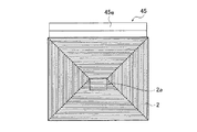
さらに、ポーチ41,42の前方には、図2および図6に示すように、略E字型を寝かせた形状の門45が設けられている。この門45は左右両端部に位置する柱部45a,45aと、中央部に位置する中央壁45bと、柱45a,45a間に架設された梁部45cとから構成されており、梁部45cの上辺の高さ方向の位置は建物本体1の1階と2階の境界部の位置とほぼ一致している。また、上記のように構成された門45の左右の開口45d,45dは、前記ポーチ41,42の前方に位置している。
ポーチ41は玄関ポーチと駐車場を兼用しており、ポーチ42は駐車場とされている。
【0029】
建物本体1の上部に設けられた屋根2は、図3に示すように、寄棟屋根であり、平面視において前記4つの突出部4,5,6,7が内側に位置するような平面視四角形状に形成されている。
つまり、平面視において屋根2の4つの軒先は、建物本体1の突出部4,5,6,7のそれぞれの先端壁4a,5a,6a,7aとほぼ一致しているか、若干突出しており、これによって屋根2は軒の出ゼロとなっている。また、前記ポーチ41,42の側部には、支柱46,46が立設されており、該支柱46,46によって屋根2の軒先部が支持されている。
【0030】
このような屋根2は、隣り合う突出部5,6間および突出部6,7間にあるポーチ41,42にかかっており、該ポーチ41,42の屋根を兼用している。同様に、隣り合う突出部4,5間および突出部5,7間にあるバルコニー40,40にかかっており、該バルコニー40,40の屋根を兼用している。
また、屋根2の頂部にはドーマ型の天窓2aが設けられており、この天窓2aによって前記小屋裏空間35への採光を確保できるようになっている。
【0031】
上記のような構成の建物によれば、以下のような効果を得ることができる。
▲1▼建物本体1に2階の床22aより約1メートル程度高いスキップ床30が設けられているが、このスキップ床30の上方空間は小屋裏空間35と連通しているので、スキップ床35上に上方空間が広い部屋31を設けることができる。つまりスキップ床30上を部屋31として有効利用できる。
【0032】
▲2▼スキップ床30の上方空間以外の小屋裏空間35に収納所36が設けられており、この収納所36とスキップ床30上の部屋31が連通しているので、部屋31から物品を収納所36に容易に収納でき、また、収納所36から物品を容易に取り出すことができる。
▲3▼部屋31の奥側の半分を囲むようにして収納所36が配置されているので、収納所36を大型のものとすることができるとともにこの収納所36への物品の出し入れも容易である。
【0033】
▲4▼また、スキップ床と収納所の床との高低の差が910mmであるので、スキップ床30上の部屋31に対して、収納所36を区画できるとともに、スキップ床30の上方空間が高くなって、スキップ床30上の部屋31の居住性が高まり、さらに、スキップ床30から収納所36に物品を容易に出し入れできる。さらに、収納所36の床37にマットレス等を敷くことによって、床37上で仮眠や睡眠をとることができる。
▲5▼1階の居間11の一部の上方空間が、スキップ床30の直下まで吹き抜けているので、居間11の天井高が高くなり、よって、該居間11の居住性が高まる。
【0034】
▲6▼建物本体1が4つの突出部4〜7を備えた平面視略十字形状に形成されているので、隣り合う突出部5,6間および突出部6,7間に、それぞれ駐車場を兼ねた玄関ポーチ41、駐車場としてのポーチ42を確保できる。また、隣り合う突出部4,5間および5,7間においては、2階においてバルコニー40,40を確保でき、1階においてテラスや庭を確保できる。
そして、屋根2は平面視において4つの突出部4〜7が内側に位置するような平面視四角形状に形成されているので、この屋根2が、隣り合う突出部の間にある場所(ポーチ41,42、バルコニー40,40、テラス、庭)用の屋根を兼ねることになる。したがって、敷地に対して許される範囲内で、建物を大きく形成しても、玄関のポーチ41、駐車場としてのポーチ42、テラス、バルコニー40,40等用の屋根が隣地と干渉するのを防止できる。
【0035】
▲7▼また、隣り合う突出部間に壁を設けることによって、建物本体1の外側に屋根付きの新たな部屋を設けることができる。この場合、1階では突出部4,5間および突出部4,7間にあるテラスに平面視においてL字状の壁を設け、この壁を突出部5の先端壁5a、突出部4の先端壁4a、突出部7の先端壁7aに連結することによって、このテラスを新たな部屋とすることができる。また、2階では同様にしてバルコニー40,40に、平面視においてL字状の壁を設け、この壁を突出部5の先端壁5a、突出部4の先端壁4a、突出部7の先端壁7aに連結することによって、バルコニー40,40を新たな部屋とすることができる。
【0036】
▲8▼突出部5,7の先端壁5a,7aが建物の敷地境界に近接して配置されているので、建物本体1を可能な限り大きく形成でき、しかも、屋根3は突出部5,絵7の先端壁5a,7aに対してほぼ軒の出ゼロであるので、この屋根2が敷地境界隣の隣地と干渉するのを防止できる。
【0037】
▲9▼建物本体1の2階には、バルコニー40,40が突出部5,7の側壁5d,7dに面して配置されているので、建物本体1の屋根2によってこのバルコニー40,40の屋根を兼ねることができ、バルコニー専用の屋根を別途形成する必要がない。
突出部5,7の側壁5d,7dに、1階においては掃出し窓5e,7eが設けられ、2階においては掃出し窓5f,7fが設けられているので、この突出部5,7と、それに隣り合う突出部4の間に設けられた、テラスやバルコニー40,40に容易に出入りでき、また、その際に建物本体1の屋根2によって雨を凌ぐことができる。
突出部6の側壁6dに、玄関扉6eが設けられているので、この突出部6と、それに隣り合う突出部5の間に設けられた、駐車場兼用の玄関ポーチ41に容易に出入りでき、また、その際に建物本体1の屋根2によって雨を凌ぐことができる。
【0038】
なお、上記実施の形態では、建物本体1をパネル工法で構築したものとしたが、これに限らず、在来工法、ツーバイフォー工法、ユニット工法等によって構築してもよい。
また、スキップ床30は、建物本体1に1ヶ所設けたが、これに限ることなく、複数箇所設けてもよい。さらに、スキップ床30と収納所36の床37との間に階段や梯子を設けてもよい。
【0039】
【発明の効果】
以上説明したように、請求項1に記載の発明によれば、スキップ床の上方空間が小屋裏空間と連通しているので、スキップ床上を部屋として有効利用できる。
【0040】
請求項2に記載の発明によれば、収納所とスキップ床上の部屋が連通しているので、このスキップ床上の部屋から収納所に物品を容易に出し入れできる。
【0041】
請求項3に記載の発明によれば、収納所がスキップ床上の部屋の周囲に配置されているので、広い収納所を容易に設けることができるとともに、この収納所への物品の出し入れも容易である。
【0042】
請求項4に記載の発明によれば、スキップ床と収納所の床との高低の差が900mm〜1000mmであるので、スキップ床上の部屋に対して、収納所を区画できるとともに、スキップ床の上方空間が高くなって、スキップ床上の部屋の居住性が高まり、さらに、スキップ床から収納所に物品を容易に出し入れできる。
【0043】
請求項5に記載の発明によれば、下方の階の部屋の少なくとも一部の上方空間が、スキップ床の直下まで吹き抜けているので、下方の階の部屋の居住性が高まる。
【図面の簡単な説明】
【図1】本発明に係る建物の一例を示すもので、建物の正面図である。
【図2】同、背面図である。
【図3】同、平面図である。
【図4】同、右側面図である。
【図5】同、左側面図である。
【図6】同、図1におけるA−A断面図である。
【図7】同、図1におけるB−B断面図である。
【図8】同、図1におけるC−C断面図である。
【図9】同、建物の縦断面図である。
【符号の説明】
1 建物本体
22a 所定の階(2階)の床
23 吹き抜け空間
27 階段
30 スキップ床
31 スキップ床上の部屋
35 小屋裏空間
36 収納所
37 収納所の床[0001]
TECHNICAL FIELD OF THE INVENTION
The present invention relates to a building provided with a skip floor that is higher than a floor of a predetermined floor by a predetermined height in a main body of the building.
[0002]
[Background technology]
As an example of a house having a skip floor, a house described in
[0003]
[Patent Document 1]
JP-A-2002-317564
[Problems to be solved by the invention]
By the way, in the house described in
[0005]
The present invention has been made in view of the above circumstances, and it is an object of the present invention to provide a building which can be used as a room on a skip floor even if a skip floor higher than a floor on a predetermined floor by a predetermined height is provided.
[0006]
[Means for Solving the Problems]
In order to solve the above-mentioned problem, the invention according to
A
[0007]
Here, when the space above the
Further, the entire upper part of the
[0008]
According to the first aspect of the present invention, since the space above the
[0009]
According to a second aspect of the present invention, in the building according to the first aspect, a storage space is provided in a
[0010]
The
[0011]
According to the second aspect of the present invention, since the
[0012]
According to a third aspect of the present invention, in the building according to the second aspect,
The
[0013]
When the
[0014]
According to the third aspect of the present invention, since the
[0015]
According to a fourth aspect of the present invention, in the building according to the second or third aspect, a difference in height between the
[0016]
Here, the difference between the height of the
On the other hand, if it exceeds 1000 mm, the floor 37 of the
[0017]
According to the fourth aspect of the present invention, since the height difference between the
[0018]
The invention according to
A space above at least a part of a room (living room 11) on a floor (for example, the first floor) lower than the predetermined floor (for example, the second floor) is blown down to just below the
[0019]
According to the invention described in
[0020]
BEST MODE FOR CARRYING OUT THE INVENTION
Hereinafter, embodiments of the present invention will be described with reference to FIGS.
The buildings shown in these figures are constructed by a panel method in which components such as walls, floors, and roofs are preliminarily panelized in factories, and these panels are assembled at the construction site to build houses and other buildings. The building is a two-story building having a
[0021]
The
On the first floor of the
In the protruding
[0022]
On the second floor of the
[0023]
In the protruding
As shown in FIGS. 8 and 9, the
[0024]
A
Further, the
[0025]
6 and 7, the projecting
The protruding
The upper side of the
[0026]
As shown in FIG. 1 and FIG. 6, the
As shown in FIGS. 4 to 7, an
[0027]
On the second floor of the
[0028]
On the first floor of the building
Further, in front of the
The
[0029]
As shown in FIG. 3, the
That is, in plan view, the four eaves of the
[0030]
Such a
In addition, a dormer-shaped
[0031]
According to the building having the above configuration, the following effects can be obtained.
{Circle around (1)} The
[0032]
{Circle around (2)} A
{Circle around (3)} Since the
[0033]
{Circle around (4)} Since the height difference between the skip floor and the floor of the storage is 910 mm, the
{Circle over (5)} Since a part of the upper space of the
[0034]
{Circle over (6)} Since the
Since the
[0035]
{Circle around (7)} By providing a wall between adjacent projections, a new room with a roof can be provided outside the
[0036]
{Circle around (8)} Since the
[0037]
{Circle over (9)} On the second floor of the building
The
Since the
[0038]
In the above-described embodiment, the
In addition, the
[0039]
【The invention's effect】
As described above, according to the first aspect of the present invention, since the space above the skip floor communicates with the space behind the hut, the space above the skip floor can be effectively used as a room.
[0040]
According to the second aspect of the present invention, since the storage room and the room on the skip floor communicate with each other, articles can be easily taken in and out of the storage room from the room on the skip floor.
[0041]
According to the third aspect of the present invention, since the storage place is arranged around the room on the skip floor, a large storage place can be easily provided, and articles can be easily put in and out of this storage place. is there.
[0042]
According to the fourth aspect of the present invention, since the height difference between the skip floor and the floor of the storage room is 900 mm to 1000 mm, the storage room can be divided with respect to the room on the skip floor, and the space above the skip floor can be defined. The space is increased, and the livability of the room on the skip floor is enhanced, and articles can be easily taken in and out of the storage from the skip floor.
[0043]
According to the fifth aspect of the present invention, at least a part of the upper space of the room on the lower floor is blown up to just below the skip floor, so that the livability of the room on the lower floor is enhanced.
[Brief description of the drawings]
FIG. 1 shows an example of a building according to the present invention, and is a front view of the building.
FIG. 2 is a rear view of the same.
FIG. 3 is a plan view of the same.
FIG. 4 is a right side view of the same.
FIG. 5 is a left side view of the same.
FIG. 6 is a sectional view taken along the line AA in FIG. 1;
FIG. 7 is a sectional view taken along the line BB in FIG. 1;
FIG. 8 is a sectional view taken along the line CC in FIG.
FIG. 9 is a longitudinal sectional view of the same building.
[Explanation of symbols]
1 Building main body 22a Floor of predetermined floor (second floor) 23
Claims (5)
前記所定の階の床から前記スキップ床に至る階段が設けられ、前記スキップ床の上方空間が小屋裏空間と連通していることを特徴とする建物。In a building provided with a skip floor higher than the floor of the predetermined floor by a predetermined height in the building body,
A building, wherein a stairway from the floor of the predetermined floor to the skip floor is provided, and a space above the skip floor communicates with a space behind the cabin.
前記スキップ床の上方空間以外の小屋裏空間に収納所が設けられており、この収納所と前記スキップ床上の部屋が連通していることを特徴とする建物。In the building of claim 1,
A building, wherein a storage room is provided in a space behind the hut other than the space above the skip floor, and the storage room communicates with a room on the skip floor.
前記収納所は、前記スキップ床上の部屋の周囲に配置されていることを特徴とする建物。In the building according to claim 2,
The said storage is arranged around the room on the said skip floor, The building characterized by the above-mentioned.
前記所定の階より下方の階の部屋の少なくとも一部の上方空間が、前記スキップ床の直下まで吹き抜けていることを特徴とする建物。In the building according to any one of claims 1 to 4,
A building, wherein at least a part of an upper space of a room on a floor lower than the predetermined floor is blown right below the skip floor.
Priority Applications (1)
| Application Number | Priority Date | Filing Date | Title |
|---|---|---|---|
| JP2003104416A JP4095485B2 (en) | 2003-04-08 | 2003-04-08 | building |
Applications Claiming Priority (1)
| Application Number | Priority Date | Filing Date | Title |
|---|---|---|---|
| JP2003104416A JP4095485B2 (en) | 2003-04-08 | 2003-04-08 | building |
Publications (2)
| Publication Number | Publication Date |
|---|---|
| JP2004308283A true JP2004308283A (en) | 2004-11-04 |
| JP4095485B2 JP4095485B2 (en) | 2008-06-04 |
Family
ID=33467254
Family Applications (1)
| Application Number | Title | Priority Date | Filing Date |
|---|---|---|---|
| JP2003104416A Expired - Fee Related JP4095485B2 (en) | 2003-04-08 | 2003-04-08 | building |
Country Status (1)
| Country | Link |
|---|---|
| JP (1) | JP4095485B2 (en) |
Cited By (4)
| Publication number | Priority date | Publication date | Assignee | Title |
|---|---|---|---|---|
| JP2009155873A (en) * | 2007-12-26 | 2009-07-16 | Sumitomo Forestry Co Ltd | Building in which natural environment is taken |
| JP2009197460A (en) * | 2008-02-20 | 2009-09-03 | Sumitomo Forestry Co Ltd | Building |
| JP2016141970A (en) * | 2015-01-30 | 2016-08-08 | 旭化成ホームズ株式会社 | building |
| JP2020117942A (en) * | 2019-01-24 | 2020-08-06 | 積水ハウス株式会社 | Storage room, and building |
-
2003
- 2003-04-08 JP JP2003104416A patent/JP4095485B2/en not_active Expired - Fee Related
Cited By (5)
| Publication number | Priority date | Publication date | Assignee | Title |
|---|---|---|---|---|
| JP2009155873A (en) * | 2007-12-26 | 2009-07-16 | Sumitomo Forestry Co Ltd | Building in which natural environment is taken |
| JP2009197460A (en) * | 2008-02-20 | 2009-09-03 | Sumitomo Forestry Co Ltd | Building |
| JP2016141970A (en) * | 2015-01-30 | 2016-08-08 | 旭化成ホームズ株式会社 | building |
| JP2020117942A (en) * | 2019-01-24 | 2020-08-06 | 積水ハウス株式会社 | Storage room, and building |
| JP7206946B2 (en) | 2019-01-24 | 2023-01-18 | 積水ハウス株式会社 | Storage room and building |
Also Published As
| Publication number | Publication date |
|---|---|
| JP4095485B2 (en) | 2008-06-04 |
Similar Documents
| Publication | Publication Date | Title |
|---|---|---|
| JP6436130B2 (en) | Residential | |
| JP6933904B2 (en) | Housing | |
| JP4095485B2 (en) | building | |
| JP5886778B2 (en) | Unit building | |
| JP2008303570A (en) | Building with balcony | |
| JP2009013581A (en) | Apartment house with loft | |
| JP2009121093A (en) | Building | |
| JPH08209954A (en) | Building having housing chamber | |
| JP2008133649A (en) | Building having daylighting storage structure part | |
| JPH10231628A (en) | House | |
| JP2005226263A (en) | Building | |
| JP2019199786A (en) | building | |
| JP2018150802A (en) | Housing | |
| JP2000265689A (en) | Dwelling house and multiple dwelling house | |
| JPH10131522A (en) | Dwelling | |
| JP2008045300A (en) | Building with daylighting structure section | |
| JP2008223474A (en) | Building with storage room | |
| JPH10292646A (en) | House with earthen floor space | |
| JPS6198875A (en) | Structure of building | |
| JP2017115523A (en) | House | |
| JP2017115524A (en) | Housing | |
| JP2002242458A (en) | Residence having court facing to porch | |
| JP2001303777A (en) | House built in site lower than road surface | |
| JP5411517B2 (en) | 3-story apartment house | |
| JPH11117547A (en) | Multiple dwelling house |
Legal Events
| Date | Code | Title | Description |
|---|---|---|---|
| A621 | Written request for application examination |
Free format text: JAPANESE INTERMEDIATE CODE: A621 Effective date: 20050408 |
|
| A977 | Report on retrieval |
Free format text: JAPANESE INTERMEDIATE CODE: A971007 Effective date: 20070621 |
|
| A131 | Notification of reasons for refusal |
Free format text: JAPANESE INTERMEDIATE CODE: A131 Effective date: 20070626 |
|
| A521 | Written amendment |
Free format text: JAPANESE INTERMEDIATE CODE: A523 Effective date: 20070816 |
|
| A131 | Notification of reasons for refusal |
Free format text: JAPANESE INTERMEDIATE CODE: A131 Effective date: 20071023 |
|
| A521 | Written amendment |
Free format text: JAPANESE INTERMEDIATE CODE: A523 Effective date: 20071214 |
|
| A711 | Notification of change in applicant |
Free format text: JAPANESE INTERMEDIATE CODE: A712 Effective date: 20080118 |
|
| RD04 | Notification of resignation of power of attorney |
Free format text: JAPANESE INTERMEDIATE CODE: A7424 Effective date: 20080206 |
|
| TRDD | Decision of grant or rejection written | ||
| A01 | Written decision to grant a patent or to grant a registration (utility model) |
Free format text: JAPANESE INTERMEDIATE CODE: A01 Effective date: 20080304 |
|
| A61 | First payment of annual fees (during grant procedure) |
Free format text: JAPANESE INTERMEDIATE CODE: A61 Effective date: 20080307 |
|
| FPAY | Renewal fee payment (event date is renewal date of database) |
Free format text: PAYMENT UNTIL: 20110314 Year of fee payment: 3 |
|
| R150 | Certificate of patent or registration of utility model |
Free format text: JAPANESE INTERMEDIATE CODE: R150 |
|
| FPAY | Renewal fee payment (event date is renewal date of database) |
Free format text: PAYMENT UNTIL: 20110314 Year of fee payment: 3 |
|
| FPAY | Renewal fee payment (event date is renewal date of database) |
Free format text: PAYMENT UNTIL: 20120314 Year of fee payment: 4 |
|
| FPAY | Renewal fee payment (event date is renewal date of database) |
Free format text: PAYMENT UNTIL: 20120314 Year of fee payment: 4 |
|
| FPAY | Renewal fee payment (event date is renewal date of database) |
Free format text: PAYMENT UNTIL: 20130314 Year of fee payment: 5 |
|
| FPAY | Renewal fee payment (event date is renewal date of database) |
Free format text: PAYMENT UNTIL: 20140314 Year of fee payment: 6 |
|
| LAPS | Cancellation because of no payment of annual fees |