JP2004308009A - Method of applying environmental and bond coatings to turbine flowpath parts - Google Patents
Method of applying environmental and bond coatings to turbine flowpath parts Download PDFInfo
- Publication number
- JP2004308009A JP2004308009A JP2004109825A JP2004109825A JP2004308009A JP 2004308009 A JP2004308009 A JP 2004308009A JP 2004109825 A JP2004109825 A JP 2004109825A JP 2004109825 A JP2004109825 A JP 2004109825A JP 2004308009 A JP2004308009 A JP 2004308009A
- Authority
- JP
- Japan
- Prior art keywords
- coating
- shroud
- thickness
- flow path
- edge
- Prior art date
- Legal status (The legal status is an assumption and is not a legal conclusion. Google has not performed a legal analysis and makes no representation as to the accuracy of the status listed.)
- Granted
Links
- 238000000576 coating method Methods 0.000 title claims description 93
- 238000000034 method Methods 0.000 title claims description 55
- 230000007613 environmental effect Effects 0.000 title description 2
- 238000003754 machining Methods 0.000 claims abstract description 8
- 239000011248 coating agent Substances 0.000 claims description 79
- 239000000463 material Substances 0.000 claims description 20
- 238000005507 spraying Methods 0.000 claims description 10
- XAGFODPZIPBFFR-UHFFFAOYSA-N aluminium Chemical compound [Al] XAGFODPZIPBFFR-UHFFFAOYSA-N 0.000 claims 1
- 229910052782 aluminium Inorganic materials 0.000 claims 1
- 238000007749 high velocity oxygen fuel spraying Methods 0.000 claims 1
- 239000007921 spray Substances 0.000 abstract description 27
- 239000000758 substrate Substances 0.000 abstract description 3
- 238000010276 construction Methods 0.000 abstract 1
- 238000007751 thermal spraying Methods 0.000 description 12
- 239000007789 gas Substances 0.000 description 6
- 230000006872 improvement Effects 0.000 description 6
- PXHVJJICTQNCMI-UHFFFAOYSA-N Nickel Chemical compound [Ni] PXHVJJICTQNCMI-UHFFFAOYSA-N 0.000 description 3
- 230000008901 benefit Effects 0.000 description 3
- 239000010410 layer Substances 0.000 description 3
- 230000008569 process Effects 0.000 description 3
- 239000012720 thermal barrier coating Substances 0.000 description 3
- 229910000951 Aluminide Inorganic materials 0.000 description 2
- 229910000943 NiAl Inorganic materials 0.000 description 2
- NPXOKRUENSOPAO-UHFFFAOYSA-N Raney nickel Chemical compound [Al].[Ni] NPXOKRUENSOPAO-UHFFFAOYSA-N 0.000 description 2
- 238000005422 blasting Methods 0.000 description 2
- 239000000919 ceramic Substances 0.000 description 2
- 230000007797 corrosion Effects 0.000 description 2
- 238000005260 corrosion Methods 0.000 description 2
- 238000000151 deposition Methods 0.000 description 2
- 238000011161 development Methods 0.000 description 2
- 230000018109 developmental process Effects 0.000 description 2
- 238000010586 diagram Methods 0.000 description 2
- 238000012986 modification Methods 0.000 description 2
- 230000004048 modification Effects 0.000 description 2
- 229910052759 nickel Inorganic materials 0.000 description 2
- 230000001590 oxidative effect Effects 0.000 description 2
- BASFCYQUMIYNBI-UHFFFAOYSA-N platinum Chemical compound [Pt] BASFCYQUMIYNBI-UHFFFAOYSA-N 0.000 description 2
- 230000003252 repetitive effect Effects 0.000 description 2
- 229920002379 silicone rubber Polymers 0.000 description 2
- 239000004945 silicone rubber Substances 0.000 description 2
- XLYOFNOQVPJJNP-UHFFFAOYSA-N water Substances O XLYOFNOQVPJJNP-UHFFFAOYSA-N 0.000 description 2
- 229910018072 Al 2 O 3 Inorganic materials 0.000 description 1
- 229910052684 Cerium Inorganic materials 0.000 description 1
- 229910052692 Dysprosium Inorganic materials 0.000 description 1
- 229910052691 Erbium Inorganic materials 0.000 description 1
- 229910052693 Europium Inorganic materials 0.000 description 1
- 229910052688 Gadolinium Inorganic materials 0.000 description 1
- 229910052689 Holmium Inorganic materials 0.000 description 1
- 229910052765 Lutetium Inorganic materials 0.000 description 1
- 229910052779 Neodymium Inorganic materials 0.000 description 1
- 229910052777 Praseodymium Inorganic materials 0.000 description 1
- 229910052772 Samarium Inorganic materials 0.000 description 1
- 229910001347 Stellite Inorganic materials 0.000 description 1
- 239000004809 Teflon Substances 0.000 description 1
- 229920006362 Teflon® Polymers 0.000 description 1
- 229910052771 Terbium Inorganic materials 0.000 description 1
- 229910052775 Thulium Inorganic materials 0.000 description 1
- 229910052769 Ytterbium Inorganic materials 0.000 description 1
- 230000001464 adherent effect Effects 0.000 description 1
- 229910045601 alloy Inorganic materials 0.000 description 1
- 239000000956 alloy Substances 0.000 description 1
- 230000000712 assembly Effects 0.000 description 1
- 238000000429 assembly Methods 0.000 description 1
- 230000004888 barrier function Effects 0.000 description 1
- 230000008859 change Effects 0.000 description 1
- AHICWQREWHDHHF-UHFFFAOYSA-N chromium;cobalt;iron;manganese;methane;molybdenum;nickel;silicon;tungsten Chemical compound C.[Si].[Cr].[Mn].[Fe].[Co].[Ni].[Mo].[W] AHICWQREWHDHHF-UHFFFAOYSA-N 0.000 description 1
- 238000004140 cleaning Methods 0.000 description 1
- 239000011247 coating layer Substances 0.000 description 1
- 230000002301 combined effect Effects 0.000 description 1
- 230000008021 deposition Effects 0.000 description 1
- 239000000428 dust Substances 0.000 description 1
- 229920001971 elastomer Polymers 0.000 description 1
- 239000002360 explosive Substances 0.000 description 1
- 238000010289 gas flame spraying Methods 0.000 description 1
- 238000010438 heat treatment Methods 0.000 description 1
- 229910052742 iron Inorganic materials 0.000 description 1
- 229910052751 metal Inorganic materials 0.000 description 1
- 239000002184 metal Substances 0.000 description 1
- 239000007769 metal material Substances 0.000 description 1
- 238000005088 metallography Methods 0.000 description 1
- 150000002739 metals Chemical class 0.000 description 1
- 239000000203 mixture Substances 0.000 description 1
- 229910000907 nickel aluminide Inorganic materials 0.000 description 1
- 230000003647 oxidation Effects 0.000 description 1
- 238000007254 oxidation reaction Methods 0.000 description 1
- 238000007750 plasma spraying Methods 0.000 description 1
- 239000004033 plastic Substances 0.000 description 1
- 229920003023 plastic Polymers 0.000 description 1
- 229910052697 platinum Inorganic materials 0.000 description 1
- 239000000843 powder Substances 0.000 description 1
- 238000003825 pressing Methods 0.000 description 1
- 238000002203 pretreatment Methods 0.000 description 1
- 239000005060 rubber Substances 0.000 description 1
- 229910000601 superalloy Inorganic materials 0.000 description 1
- 230000003746 surface roughness Effects 0.000 description 1
- 238000010998 test method Methods 0.000 description 1
Images


Classifications
-
- C—CHEMISTRY; METALLURGY
- C23—COATING METALLIC MATERIAL; COATING MATERIAL WITH METALLIC MATERIAL; CHEMICAL SURFACE TREATMENT; DIFFUSION TREATMENT OF METALLIC MATERIAL; COATING BY VACUUM EVAPORATION, BY SPUTTERING, BY ION IMPLANTATION OR BY CHEMICAL VAPOUR DEPOSITION, IN GENERAL; INHIBITING CORROSION OF METALLIC MATERIAL OR INCRUSTATION IN GENERAL
- C23C—COATING METALLIC MATERIAL; COATING MATERIAL WITH METALLIC MATERIAL; SURFACE TREATMENT OF METALLIC MATERIAL BY DIFFUSION INTO THE SURFACE, BY CHEMICAL CONVERSION OR SUBSTITUTION; COATING BY VACUUM EVAPORATION, BY SPUTTERING, BY ION IMPLANTATION OR BY CHEMICAL VAPOUR DEPOSITION, IN GENERAL
- C23C4/00—Coating by spraying the coating material in the molten state, e.g. by flame, plasma or electric discharge
- C23C4/18—After-treatment
-
- C—CHEMISTRY; METALLURGY
- C23—COATING METALLIC MATERIAL; COATING MATERIAL WITH METALLIC MATERIAL; CHEMICAL SURFACE TREATMENT; DIFFUSION TREATMENT OF METALLIC MATERIAL; COATING BY VACUUM EVAPORATION, BY SPUTTERING, BY ION IMPLANTATION OR BY CHEMICAL VAPOUR DEPOSITION, IN GENERAL; INHIBITING CORROSION OF METALLIC MATERIAL OR INCRUSTATION IN GENERAL
- C23C—COATING METALLIC MATERIAL; COATING MATERIAL WITH METALLIC MATERIAL; SURFACE TREATMENT OF METALLIC MATERIAL BY DIFFUSION INTO THE SURFACE, BY CHEMICAL CONVERSION OR SUBSTITUTION; COATING BY VACUUM EVAPORATION, BY SPUTTERING, BY ION IMPLANTATION OR BY CHEMICAL VAPOUR DEPOSITION, IN GENERAL
- C23C4/00—Coating by spraying the coating material in the molten state, e.g. by flame, plasma or electric discharge
- C23C4/02—Pretreatment of the material to be coated, e.g. for coating on selected surface areas
-
- C—CHEMISTRY; METALLURGY
- C23—COATING METALLIC MATERIAL; COATING MATERIAL WITH METALLIC MATERIAL; CHEMICAL SURFACE TREATMENT; DIFFUSION TREATMENT OF METALLIC MATERIAL; COATING BY VACUUM EVAPORATION, BY SPUTTERING, BY ION IMPLANTATION OR BY CHEMICAL VAPOUR DEPOSITION, IN GENERAL; INHIBITING CORROSION OF METALLIC MATERIAL OR INCRUSTATION IN GENERAL
- C23C—COATING METALLIC MATERIAL; COATING MATERIAL WITH METALLIC MATERIAL; SURFACE TREATMENT OF METALLIC MATERIAL BY DIFFUSION INTO THE SURFACE, BY CHEMICAL CONVERSION OR SUBSTITUTION; COATING BY VACUUM EVAPORATION, BY SPUTTERING, BY ION IMPLANTATION OR BY CHEMICAL VAPOUR DEPOSITION, IN GENERAL
- C23C4/00—Coating by spraying the coating material in the molten state, e.g. by flame, plasma or electric discharge
- C23C4/12—Coating by spraying the coating material in the molten state, e.g. by flame, plasma or electric discharge characterised by the method of spraying
Abstract
Description
本発明は、翼形部及びシュラウドのようなタービンエンジンアセンブリ及び部品に溶射法を用いて耐環境性皮膜又はボンドコーティングを施工する方法に関し、具体的には、長寿命遮熱トップコートの施工を可能にしつつ、高温、酸化性及び腐食性雰囲気中で被覆部品を保護するのに必要な基本品質特性を有するMCrAlYその他のHVOF皮膜を施工する方法に関する。 The present invention relates to a method of applying an environmentally resistant coating or bond coating to turbine engine assemblies and components, such as airfoils and shrouds, using a thermal spray process, and more particularly, to applying a long-life thermal barrier topcoat. The present invention relates to a method of applying MCrAlY or other HVOF coatings having the basic quality characteristics necessary to protect coated parts in high temperature, oxidizing and corrosive atmospheres while enabling.
従来技術では、高温、酸化性環境及び高温腐食性ガスの複合作用からガスタービンの流路(ホットセクション)内及びその近傍のタービン翼形部及びシュラウドを保護するためタービン皮膜に関する多数の系及び改良が開示されている。こうした改良としては、翼形部に用いられる材料の新たな開発、特殊で高価なニッケル基超合金が挙げられる。その他の解決法としては、耐環境性皮膜系及び遮熱コーティング系を始めとする皮膜系の施工が挙げられる。耐環境性皮膜系には、ニッケルアルミナイド、白金アルミナイド及びこれらの組合せがある。公知の皮膜施工法には、特に限定されないが、減圧プラズマ溶射(LPPS)法、高速ガスフレーム溶射(HVOF)法及び爆発溶射(D−gun)法を始めとする溶射技術があり、これらはすべて所定の組成の粉体を溶射する。 The prior art discloses a number of turbine coating systems and improvements to protect turbine airfoils and shrouds in and near gas turbine flow paths (hot sections) from the combined effects of high temperature, oxidizing environments and hot corrosive gases. Is disclosed. These improvements include new developments in the materials used for airfoils and special and expensive nickel-based superalloys. Other solutions include the application of coating systems, including environmentally resistant coating systems and thermal barrier coating systems. Environmentally resistant coating systems include nickel aluminides, platinum aluminides and combinations thereof. Known coating methods include, but are not limited to, low pressure plasma spraying (LPPS), high velocity gas flame spraying (HVOF), and explosive spraying (D-gun), and other spraying techniques, all of which are known. Thermal spraying of a powder having a predetermined composition.
かかる皮膜及びその施工法において皮膜系の寿命を延ばす幾多の改良が開示されており、そうした改良の開発は現在も続けられている。ある種の皮膜系では、耐環境性皮膜上にセラミックの形態の遮熱コーティング(TBC)が設けられる。他の皮膜系では、翼形部とセラミック層の間の中間層として、MCrAlYのようなボンドコートが設けられる。ここで、MはNi、Co、Fe又はこれらの元素の組合せから選択される元素であり、YはCe、Pr、Nd、Pm、Sm、Eu、Gd、Tb、Dy、Ho、Er、Tm、Yb、Lu及びYtのような痕跡量金属である。ボンドコートは皮膜系の耐環境性能も向上させる。アルミナイド及びMCrAlY合金を始めとする皮膜は、実質的にγ相からなるか、或いはγ+γ′相からなるかに応じて、非脆性となることもあれば、脆性となることもある。 Numerous improvements have been disclosed in such coatings and methods of applying them that extend the life of the coating system, and the development of such improvements is ongoing. In some coating systems, a thermal barrier coating (TBC) in the form of a ceramic is provided on the environmentally resistant coating. In other coating systems, a bond coat such as MCrAlY is provided as an intermediate layer between the airfoil and the ceramic layer. Here, M is an element selected from Ni, Co, Fe or a combination of these elements, and Y is Ce, Pr, Nd, Pm, Sm, Eu, Gd, Tb, Dy, Ho, Er, Tm, Trace metals such as Yb, Lu and Yt. The bond coat also improves the environmental performance of the coating system. Coatings, including aluminides and MCrAlY alloys, can be non-brittle or brittle, depending on whether they consist essentially of a γ phase or a γ + γ 'phase.
耐環境性皮膜の分野での数多くの改良にもかかわらず、公知のコーティング法では、部品の縁部、特に高圧タービンシュラウド(「HPT」シュラウド)や低圧タービンシュラウド(「LPT」シュラウド)その他同様のタービン流路内の部品などの鋭角縁部に、十分な厚さの皮膜を均一に設けることができないという問題が依然として存在する。かかる流路部品への皮膜の施工は高速ガスフレーム(「HVOF」)溶射法を用いてなされることが多く、HVOFはロボット制御されることが多い。しかし、公知の工具及び方法を用いると、HVOF法では、シュラウドのような部品の前縁部及び後縁部で皮膜が薄くなり、施工したままの皮膜は縁部で丸みを帯びる傾向がある。このように丸みを帯びると、皮膜は縁部を所望の形状に適切に機械加工するには不十分な厚さとなり、縁部が露出されるか、或いはタービン作動時に基材縁部を保護するには不十分な皮膜を生じかねない。 Despite numerous improvements in the field of environmentally resistant coatings, known coating methods involve component edges, particularly high pressure turbine shrouds ("HPT" shrouds) and low pressure turbine shrouds ("LPT" shrouds) and similar. The problem still remains that a coating of sufficient thickness cannot be provided uniformly on sharp edges such as components in the turbine flow path. The application of a coating to such flow path components is often performed using a high-speed gas flame (“HVOF”) thermal spraying method, and the HVOF is often controlled by a robot. However, using known tools and methods, the HVOF method tends to have a thinner coating at the leading and trailing edges of components such as shrouds, and the as applied coating tends to be rounded at the edges. When rounded in this manner, the coating is of insufficient thickness to properly machine the edge to the desired shape, exposing the edge or protecting the substrate edge during turbine operation. May produce insufficient film.
必要とされているのは、ブレード、シュラウドその他の流路部品の縁部その他の流路面が十分に被覆されて、後段で所望の縁部形状にするための機械加工ができ、それでもなお下地をなす部品を保護するのに適した皮膜厚さをもたらすことができる費用効率の高い皮膜施工法である。 What is needed is that the edges and other flow surfaces of the blades, shrouds and other flow components are adequately covered and machined to the desired edge shape at a later stage, while still providing the substrate. It is a cost-effective coating method that can provide a coating thickness suitable for protecting the components made.
本発明の技術は、溶射法、特にHVOF法を用いて皮膜を施工するに当たり、後段での機械加工が可能となる十分な厚さを流路部品の縁部で達成するための新たな改良を提供する。本発明は、HVOF法で施工されるMCrAlY及びNiAl皮膜に用いるために開発されたが、本発明は、溶射法で成膜されるその他あらゆる皮膜に好適に用いることができる。 The technique of the present invention provides a new improvement in achieving a sufficient thickness at the edge of the flow path component at the time of applying a coating using a thermal spraying method, particularly an HVOF method, so that machining can be performed at a later stage. provide. Although the present invention has been developed for use with MCrAlY and NiAl coatings applied by the HVOF method, the present invention can be suitably used for any other coatings formed by thermal spraying.
本発明の一つの利点は、皮膜の厚さを調整できることである。特に、本発明では、皮膜の密度又は健全性を犠牲にすることも、その他後段の機械加工時に皮膜を損なうこともなく、部品縁部での皮膜の厚さを増大させることができる。従って、本発明は、機械加工の可能な望ましい皮膜厚さを与えることができ、しかもなお最終部品に改善された耐腐食性能及び耐酸化性能を与える。本発明に従って表面を被覆した翼形部、シュラウドその他の流路部品は、効率の改善に資する空力的に優れたガス流路の形成に必要な寸法及び仕様に機械加工することができ、なおかつ望ましい耐熱性及び耐食性を与えるのに十分な皮膜厚さを有する。 One advantage of the present invention is that the thickness of the coating can be adjusted. In particular, the present invention can increase the thickness of the coating at the edge of the component without sacrificing the density or soundness of the coating or otherwise damaging the coating during subsequent machining. Thus, the present invention can provide a desirable machineable coating thickness while still providing improved corrosion and oxidation resistance to the final part. Airfoils, shrouds and other flow components coated in accordance with the present invention can be machined and desirably machined to the dimensions and specifications required to create aerodynamic gas flow paths that contribute to improved efficiency. It has a coating thickness sufficient to provide heat and corrosion resistance.
本発明の方法のもう一つの利点は、当該方法が、新品のシュラウドにも、修理済又は修理中のシュラウドにも適用できることである。これらの方法は、再現が適度に容易で予測可能でかつ費用効率の高いHVOF法によって、厚いNiAl及び他のMCrAlY皮膜を得るための簡単で効果的な技術を提供する。 Another advantage of the method of the present invention is that the method is applicable to new shrouds as well as to shrouds that have been repaired or are being repaired. These methods provide a simple and effective technique for obtaining thick NiAl and other MCrAlY coatings by a reasonably easy, predictable and cost-effective HVOF method for reproduction.
本発明のその他の特徴及び利点は、好ましい実施形態に関する以下の詳細な説明を、本発明の原理を例示的に示す添付図面と併せて参照することによって明らかになろう。 Other features and advantages of the present invention will become apparent from the following detailed description of the preferred embodiments, taken in conjunction with the accompanying drawings, which illustrate, by way of example, the principles of the invention.
本発明は、流路部品の被覆方法及び装置、特に、新規な溶射方法及び装置を用いて部品縁部に厚い皮膜を設け、所定の寸法及び仕様への機械加工によって皮膜を修正する方法及び装置を提供する。図面に関しては、図面全体を通して、同一又は類似の部品を示すためできるだけ同じ参照符号を用いた。 The present invention relates to a method and an apparatus for coating a flow path component, and more particularly to a method and an apparatus for forming a thick coating on an edge of a component by using a novel thermal spraying method and apparatus and modifying the coating by machining to a predetermined size and specification. I will provide a. Throughout the drawings, the same reference numerals have been used, where possible, to designate identical or similar parts.
本発明の方法は、ガスタービンエンジンアセンブリの新品又は使用済み流路部品の被覆に用いることができる。当該方法は、MCrAlY皮膜が厚い層、好ましくは厚さ0.100インチ超の層をなすように施工する必要のある図1及び図2に示すシュラウドのようなHPTシュラウド及びLPTシュラウドに特に適している。かかる厚い皮膜は、本発明の方法に従ってHVOF溶射装置を用いて達成し得る。図3に示すように、本発明の溶射法を用いて得られる望ましい結果は、機械加工後に所定の形状及び寸法の部品を生じるように図3の鎖線16及び図4に示す所望の断面形状を有する均一な厚さの皮膜を得るための後段での皮膜の機械加工が実施できるように、部品の側縁部12及び流路面14に好ましくは厚さ約0.100〜約0.110インチの適度に均一な最終皮膜を備えたシュラウド10のような被覆部品を製造することである。図3の好ましい実施形態では、機械加工後の皮膜は約0.080インチの均一な厚さである。
The method of the present invention can be used to coat new or used flow path components of a gas turbine engine assembly. The method is particularly suitable for HPT shrouds and LPT shrouds, such as the shrouds shown in FIGS. 1 and 2 where the MCrAlY coating needs to be applied in thick layers, preferably greater than 0.100 inches thick. I have. Such thick coatings can be achieved using HVOF spray equipment according to the method of the present invention. As shown in FIG. 3, the desired result obtained using the thermal spray method of the present invention is that the desired cross-sectional shape shown in dashed
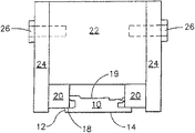
上述の通り、シュラウドその他の流路部品に厚い皮膜を溶射する際の課題は、皮膜が部品縁部で薄くなり、縁部の周りで丸みを帯びる傾向があることである。本発明の方法は、部品縁部に厚い皮膜を堆積できる溶射法及び装置を利用することによって、この問題を解決する。本発明の方法は、被覆すべき部品の1以上の後縁部に当接して配置した裏当装置の新規な使用を含む。図5に示すように、裏当材20はシュラウド10の後縁部18に対してシュラウド10の側縁部12と裏当材20の間に隅角部を形成するように配置される。図5に示す好ましい実施形態では、裏当材20は、溶射作業時に部品保持装置として役立つ取付ブロック22にシュラウド10を取付けた際に、裏当材が後縁部18に接して部分的に押圧されるような十分な厚さを有する。最も好ましくは、裏当材20はブロック22の端縁を僅かに超えて延在するような十分な幅を有しており、かくして、ネジ26などの締付手段によって裏当材をシュラウド10の本体19に押圧するための側板24を用いれば、シュラウド10の後縁部18に当接した裏当材20を効果的に封止し、被覆作業時に側縁部12と流路面14だけが溶射されるようにできる。この構成を用いると、裏当材20と側縁部12が隅角部を形成し、そこで皮膜を捕らえて側縁部12に十分に付着させて所望の皮膜ベースを形成し、続いて後側縁部12と流路面14全体が均一に被覆されるようにする。
As discussed above, the challenge in spraying thick coatings on shrouds and other flow components is that the coating tends to be thinner at the component edges and rounded around the edges. The method of the present invention solves this problem by utilizing thermal spraying methods and equipment that can deposit thick coatings on component edges. The method of the present invention involves the novel use of a backing device positioned against one or more trailing edges of the part to be coated. As shown in FIG. 5, the
本発明の新規な裏当材20は皮膜に対して非付着性である。好ましくは、裏当材の材料はゴム、プラスチック、テフロン(登録商標)などの半可撓性で非付着性の非金属材料である。さらに好ましくは、裏当材の材料はショアAデュロメータ硬度60〜110のシリコーンゴムである。最も好ましくは、裏当材の材料はショアAデュロメータ硬度80〜100のシリコーンゴムである。
The
本発明の溶射法の一実施形態では、裏当材20は、図5に示すようにシュラウド10の後縁部18に当接して配置される。好ましくは、すべての所望流路面を溶射する能力を最大限にすべく、シュラウドは、部品をその周方向エンジン位置から90°回転させ、好ましくは保持装置に取付た時に流路面14(エンジンに面してシュラウドの内径側にある)が外側を向くように部品をその長軸を中心にして180°回転させた後で、保持装置に取付ける。好ましくは、保持装置は、図6及び図7に示したものと同様なターンテーブルであって、図5〜図7に示すような複数のフィンガ又はブロック22のような取付手段を含んでおり、各フィンガ又はブロックは各々溶射作業時にシュラウド10を所望の配向に保持することができる。いずれにせよ、保持装置は、シュラウド本体19やダブテール部その他のシュラウド10の保護部位に皮膜材料が溶射されるようになりかねない隙間が残らないように、被覆すべき部品の後縁部18に裏当材20を完全に当接させて着座させることができるものでなければならない。シュラウド10の保護部位及び保持装置のブロック22の非取付部位その他の部品には、損傷及び皮膜のオーバースプレーを防ぐためテープで保護してもよい。
In one embodiment of the thermal spray method of the present invention, the
好ましい実施形態では、溶射法は回転プロセスを用いるが、この回転プロセスでは、所定速度で回転し得る図5〜図8に示すようなターンテーブルを保持装置が含んでいて、計算速度で皮膜材料を噴射するHVOF溶射ガンのプログラム可能なロボット操作をHVOF装置が行う。HVOF溶射ガンの具体例は、ノズル長12インチ及びノズル孔径0.25インチのStellite JetKote 3000であるが、その他のモデル及びタイプの溶射ガンを採用して本発明を実施することは適度な経験を積んだ当業者が容易になし得る事項である。好ましくは、回転式溶射は、ターンテーブルが回転して各シュラウドが溶射ガンを通過する際に均一な皮膜層が堆積するように、インデックス式ではなく連続式である。この実施形態では、溶射作業の手順は、シュラウドの各側縁部12に約0.01〜約0.20インチの皮膜が堆積されるまで、必要に応じてターンテーブルの回転方向を変えながら、各側縁部12に溶射することである。これは、ターンテーブル速度、溶射速度その他公知のコーティングパラメータに応じて、50サイクルほど要することもある。図7及び図8に示すように、溶射によって側縁部12に堆積させるには、溶射が好ましくはシュラウド10の流路面14に対して約45°の角度で行われるようにHVOF装置を配置する。さらに好ましい実施形態では、溶射は、シュラウド10の流路面14に対して45°の角度で施工される。側縁部12にベース皮膜を堆積させた後、シュラウド10の流路面14全体を、好ましくは回転式溶射法を用いて所望の厚さに被覆する。
In a preferred embodiment, the thermal spraying method uses a rotating process, in which the holding device includes a turntable as shown in FIGS. The HVOF device performs a programmable robotic operation of the HVOF spray gun to be sprayed. A specific example of an HVOF spray gun is a Stellite JetKote 3000 having a nozzle length of 12 inches and a nozzle hole diameter of 0.25 inches, but it has been appropriate to practice the present invention using other models and types of spray guns. This is a matter that a person skilled in the art can easily do. Preferably, the rotary spray is continuous rather than indexed so that the turntable rotates to deposit a uniform coating layer as each shroud passes through the spray gun. In this embodiment, the procedure for the thermal spraying operation is to change the direction of rotation of the turntable as necessary until about 0.01 to about 0.20 inches of coating is deposited on each
好ましい実施形態では、図7〜図9に示すように、回転式溶射法は幾つかのサイクルからなる。ベース皮膜を堆積させるため、当該サイクルは、各側縁部に施工される皮膜が均一になるようにターンテーブルの回転方向と溶射ガンの垂直方向位置を変えることを含む一連の反復側方サイクルを利用する。好ましくは、図7及び図8に示すように、反時計方向ターンテーブル回転時の溶射ガンの垂直方向運動は、右上から右下、そして右上に戻る。さらに好ましくは、ガンの垂直方向運動は溶射中の部品の形状に倣って円弧状にするか、さもなければ全サイクルを通してガンが溶射中の部品の表面から所定距離を保つように操作する。時計方向のターンテーブル回転では、ガンは左上から左下、そして左上に戻るように垂直方向に動かす。この好ましい実施形態では、厚さ約0.20インチのベース皮膜を堆積させるのに、かかる側方サイクルが約50回必要とされる。好ましくは、50回の側方サイクルは、以下の順序で行われる。即ち、ターンテーブルを時計方向に回転させながら10回の側方サイクル、ターンテーブルを反時計方向に回転させながら10回の側方サイクル、ターンテーブルを時計方向に回転させながら15回の側方サイクル及びターンテーブルを反時計方向に回転させながら15回の側方サイクルである。ただし、所望の側縁部の皮膜厚さを堆積させるため、必要に応じて追加の側方サイクルを用いてもよい。 In a preferred embodiment, as shown in FIGS. 7-9, the rotary spray method comprises several cycles. To deposit the base coating, the cycle involves a series of repetitive lateral cycles involving changing the direction of rotation of the turntable and the vertical position of the spray gun so that the coating applied to each side edge is uniform. Use. Preferably, as shown in FIGS. 7 and 8, vertical movement of the spray gun when rotating the counterclockwise turntable returns from upper right to lower right and back to upper right. More preferably, the vertical movement of the gun follows the shape of the part being sprayed and is arcuate or otherwise manipulated throughout the cycle to maintain the gun at a predetermined distance from the surface of the part being sprayed. In a clockwise turntable rotation, the gun moves vertically from top left to bottom left and back to top left. In this preferred embodiment, about 50 such side cycles are required to deposit a base coating about 0.20 inches thick. Preferably, the 50 side cycles are performed in the following order. That is, 10 lateral cycles while rotating the turntable clockwise, 10 lateral cycles while rotating the turntable counterclockwise, and 15 lateral cycles while rotating the turntable clockwise. And 15 lateral cycles while rotating the turntable counterclockwise. However, additional lateral cycles may be used as needed to deposit the desired side edge coating thickness.
次に、溶射ガンを垂直方向に(好ましくは上から下、そして上に戻るように)動かしながら、ターンテーブルの回転方向を変えることを含む一連の反復流路面サイクルを実施することによって、流路面14に最終皮膜を堆積させる。好ましくは、流路面サイクルでは溶射ガンは流路面に対してほぼ垂直に配置される。図9に示すように、最上点及び最下点での溶射ガンの位置は、各シュラウドの計算された中心に対して決定され、ターンテーブルの回転方向に応じて異なる。図7に示すように、ターンテーブルが時計方向に回転する流路面サイクルでは、ガンは所定オフセットだけ右方にずらして溶射するようにティーチングされるが、そのオフセットは、溶射がベース皮膜と重なって好ましくは右側縁部との交差部に達して皮膜を堆積するとともにデブリをなくすことができるように、流路面14の幅に基づいて定められる。図7及び図8に示すように、ターンテーブルが反時計方向に回転する流路面サイクルでは、ガンは所定オフセットだけ左方へずらして溶射するようにティーチングされるが、そのオフセットは、溶射がベース皮膜と重なって好ましくは左側縁部との交差部に達して皮膜の堆積をするとともにデブリをなくすことができるように、流路面14の幅に基づいて定められる。好ましくは、最終皮膜の厚さは約0.100インチであり、約200回の流路面サイクルを実施することによって堆積される。この好ましい実施形態では、約200回の流路面サイクルは、下記の方向にターンテーブルを回転させながら次の順序で実施される。即ち、ターンテーブルを時計方向に回転させながら50サイクル、ターンテーブルを反時計方向に回転させながら50サイクル、ターンテーブルを時計方向に回転させながら50サイクル及びターンテーブルを反時計方向に回転させながら50サイクルである。適宜、流路面サイクル完了後に、側縁部12の皮膜を厚くするため、追加の側方サイクルを実施してもよい。所望の最終皮膜厚さを得るため付加的な流路面サイクルを追加してもよい。 Next, by performing a series of repetitive flow surface cycle cycles that involve changing the direction of rotation of the turntable while moving the spray gun vertically (preferably from top to bottom and back up), 14 to deposit the final coating. Preferably, in a flow channel cycle, the spray gun is positioned substantially perpendicular to the flow channel. As shown in FIG. 9, the position of the spray gun at the top and bottom points is determined with respect to the calculated center of each shroud and varies depending on the direction of rotation of the turntable. As shown in FIG. 7, in the flow path surface cycle in which the turntable rotates clockwise, the gun is taught so as to be sprayed with a predetermined offset to the right, but the offset is such that the spray is overlapped with the base film. Preferably, it is determined based on the width of the flow path surface 14 so as to reach the intersection with the right side edge, deposit the film, and eliminate debris. As shown in FIGS. 7 and 8, in the flow path surface cycle in which the turntable rotates counterclockwise, the gun is taught to shift to the left by a predetermined offset to perform spraying. The width is determined based on the width of the flow path surface 14 so as to overlap with the coating and preferably reach the intersection with the left edge to deposit the coating and eliminate debris. Preferably, the thickness of the final coating is about 0.100 inches and is deposited by performing about 200 channel surface cycles. In this preferred embodiment, about 200 channel surface cycles are performed in the following order while rotating the turntable in the following directions. That is, 50 cycles while rotating the turntable clockwise, 50 cycles while rotating the turntable counterclockwise, 50 cycles while rotating the turntable clockwise and 50 cycles while rotating the turntable counterclockwise. It is a cycle. Optionally, after completion of the flow path cycle, additional lateral cycles may be performed to thicken the coating on the side edges 12. Additional channel cycle may be added to achieve the desired final coating thickness.
ベース皮膜及び最終皮膜の皮膜厚さを検証するため、引張ボタン(tensile button)の使用などの公知の試験方法を利用することができ、図6に示すように厚さパネルとの比較によって厚さを検証することもできる。回転式プロセスでターンテーブルを用いる場合、好ましくは、空いた取付ブロック22に引張ボタンを設け、溶射経路を通して回転させてシュラウド10と同じ速度で皮膜を堆積させる。
Known test methods, such as the use of a tensile button, can be used to verify the coating thickness of the base coating and the final coating, and by comparing the thickness with a thickness panel as shown in FIG. Can also be verified. If the turntable is used in a rotary process, preferably the
別の実施形態では、本発明の方法は、被覆前にシュラウドを前処理することを含む。前処理の目的は、被覆のため清浄で汚染されていない表面を得ることである。好ましい実施形態では、前処理は、流路面14及び側縁部12のグリットブラストのため部品をテーピングすることを含む。好ましくは、約80〜150Raの表面粗さを得るため、60〜80メッシュのAl2O3を用いてグリットブラストを行う。次いで、好ましくはウォータージェットを使用して表面を滑らかかつ清浄にするが、ウォータージェット洗浄後は、こうして処理した部品表面は汚染されていないものと考えられる。こうした表面は、オイル、埃などから清浄に保護しておかなくてはならず、部品の取扱いに際しては決して手で触れるべきではない。次に、部品を保持装置に設置し、好ましくは上述の回転式溶射法を用いて被覆する。
In another embodiment, the method of the invention comprises pretreating the shroud prior to coating. The purpose of the pretreatment is to obtain a clean and uncontaminated surface for coating. In a preferred embodiment, the pre-treatment includes taping the parts for grit blasting of the
被覆後、適宜、シュラウドを当業者に公知の方法を用いて熱処理してもよい。熱処理は、好ましくは金属組織学に基づくもので、好ましくは1μ以下の真空中で約4時間約2050°F(±25°F)にて行われる。また、被覆部品は、所望の流路形状及び寸法を回復するために機械加工してもよい。機械加工は、皮膜を損傷したり、流路部品に露出面を残したりしないように、所望の形状を回復するのに十分なだけ皮膜を除去すべきである。好ましくは、機械加工で約0.40〜約0.010インチの適度に均一な皮膜厚さを得る。さらに好ましくは、最終皮膜厚さは約0.060〜約0.090インチである。最も好ましくは、最終皮膜厚さは約0.070〜約0.080インチである。 After coating, the shroud may optionally be heat treated using methods known to those skilled in the art. The heat treatment is preferably based on metallography and is preferably performed at about 2050 ° F. (± 25 ° F.) for about 4 hours in a vacuum of 1 μm or less. Also, the coated part may be machined to restore the desired flow path shape and dimensions. Machining should remove enough of the coating to restore the desired shape without damaging the coating or leaving exposed surfaces on the flow path components. Preferably, machining provides a reasonably uniform coating thickness of about 0.40 to about 0.010 inches. More preferably, the final coating thickness is from about 0.060 to about 0.090 inches. Most preferably, the final coating thickness is between about 0.070 and about 0.080 inches.
耐環境性皮膜又はボンドコートを形成するためシュラウドにHVOF法で施工されるMCrAlY皮膜に関して本発明を説明してきたが、本発明は、HVOF法で施工できるあらゆる皮膜に使用できることは明らかであろう。本発明の技術的範囲から逸脱せずに、本発明を適用して、他の溶射皮膜及び溶射方法を利用することもできる。そこで、後段での機械加工ができるほど十分に厚い縁部を得ることができなかったために従前考慮されていなかった皮膜を使用できる可能性がある。 Although the invention has been described with reference to an MCrAlY coating applied to the shroud by an HVOF method to form an environmentally resistant coating or bond coat, it will be apparent that the invention can be used with any coating that can be applied by the HVOF method. The present invention can be applied to utilize other thermal spray coatings and thermal spraying methods without departing from the technical scope of the present invention. Therefore, there is a possibility that a coating that has not been taken into account beforehand can be used because an edge portion that is thick enough to be machined in the subsequent stage could not be obtained.
好ましい実施形態を参照して本発明を説明してきたが、本発明の技術的範囲から逸脱せずに、様々な変更を加えることができ、また構成要素を均等物で置換することができることは、当業者には明らかであろう。さらに、本発明の本質的な範囲から逸脱することなく、特定の状況又は材料を本発明の教示に適合させるべく幾多の変更を加えることもできる。従って、本発明は、本発明を実施するための最良の形態として開示した特定の実施形態に限定されるものではなく、特許請求の範囲の技術的範囲に属するあらゆる実施形態を包含する。 Although the present invention has been described with reference to preferred embodiments, various modifications can be made and components may be substituted with equivalents without departing from the scope of the invention. It will be apparent to those skilled in the art. In addition, many modifications may be made to adapt a particular situation or material to the teachings of the invention without departing from the essential scope thereof. Therefore, the present invention is not limited to the specific embodiments disclosed as the best mode for carrying out the present invention, but encompasses all embodiments belonging to the technical scope of the claims.
10 シュラウド
12 側縁部
14 流路面
18 後縁部
19 本体
20 裏当材
22 取付ブロック
24 側板
26 ネジ
DESCRIPTION OF
Claims (10)
流路面(14)と少なくとも1つの側縁部(12)と少なくとも1つの後縁部(18)とを有する流路部品(10)を準備する段階、
流路部品(10)の後縁部(18)と実質的に接するように裏当材(20)を配置する段階、及び
少なくとも1つの側縁部(12)に初期ベース皮膜(16)を施工する段階、
を含む方法。 A method for applying a thermal spray coating on a flow path component (10) of a gas turbine engine, comprising:
Providing a channel component (10) having a channel surface (14), at least one side edge (12), and at least one trailing edge (18);
Placing the backing material (20) substantially in contact with the trailing edge (18) of the flow path component (10); and applying an initial base coating (16) on at least one side edge (12). Stage to do
A method that includes
Applications Claiming Priority (2)
| Application Number | Priority Date | Filing Date | Title |
|---|---|---|---|
| US10/405,727 | 2003-04-02 | ||
| US10/405,727 US6887529B2 (en) | 2003-04-02 | 2003-04-02 | Method of applying environmental and bond coatings to turbine flowpath parts |
Publications (2)
| Publication Number | Publication Date |
|---|---|
| JP2004308009A true JP2004308009A (en) | 2004-11-04 |
| JP4912570B2 JP4912570B2 (en) | 2012-04-11 |
Family
ID=32850622
Family Applications (1)
| Application Number | Title | Priority Date | Filing Date |
|---|---|---|---|
| JP2004109825A Expired - Lifetime JP4912570B2 (en) | 2003-04-02 | 2004-04-02 | Method for applying environmentally resistant coating and bond coating on turbine flow path components |
Country Status (6)
| Country | Link |
|---|---|
| US (1) | US6887529B2 (en) |
| EP (1) | EP1464722B1 (en) |
| JP (1) | JP4912570B2 (en) |
| BR (1) | BRPI0401194B1 (en) |
| CA (1) | CA2462318C (en) |
| SG (1) | SG137669A1 (en) |
Cited By (1)
| Publication number | Priority date | Publication date | Assignee | Title |
|---|---|---|---|---|
| JP2019031970A (en) * | 2017-07-27 | 2019-02-28 | ゼネラル・エレクトリック・カンパニイ | Method and system to repair turbomachine |
Families Citing this family (15)
| Publication number | Priority date | Publication date | Assignee | Title |
|---|---|---|---|---|
| US7967924B2 (en) * | 2005-05-17 | 2011-06-28 | General Electric Company | Method for making a compositionally graded gas turbine disk |
| US20080102291A1 (en) * | 2006-10-31 | 2008-05-01 | Caterpillar Inc. | Method for coating a substrate |
| US20080299306A1 (en) * | 2007-05-30 | 2008-12-04 | Caterpillar Inc. | Multi-layer substrate and method of fabrication |
| US9995165B2 (en) | 2011-07-15 | 2018-06-12 | United Technologies Corporation | Blade outer air seal having partial coating |
| US9062558B2 (en) | 2011-07-15 | 2015-06-23 | United Technologies Corporation | Blade outer air seal having partial coating |
| US8678644B2 (en) * | 2011-08-16 | 2014-03-25 | General Electric Company | Hot gas path measurement |
| WO2014138416A1 (en) * | 2013-03-06 | 2014-09-12 | United Technologies Corporation | Fixturing for thermal spray coating of gas turbine components |
| US10858950B2 (en) | 2017-07-27 | 2020-12-08 | Rolls-Royce North America Technologies, Inc. | Multilayer abradable coatings for high-performance systems |
| US10900371B2 (en) | 2017-07-27 | 2021-01-26 | Rolls-Royce North American Technologies, Inc. | Abradable coatings for high-performance systems |
| US11117151B2 (en) * | 2017-08-23 | 2021-09-14 | Raytheon Technologies Corporation | Fixture assembly for coating combustor panels |
| US10808565B2 (en) * | 2018-05-22 | 2020-10-20 | Rolls-Royce Plc | Tapered abradable coatings |
| CN108950457A (en) * | 2018-06-11 | 2018-12-07 | 中国航发哈尔滨东安发动机有限公司 | A kind of impeller chimney class part heat spraying method |
| US11707815B2 (en) * | 2019-07-09 | 2023-07-25 | General Electric Company | Creating 3D mark on protective coating on metal part using mask and metal part so formed |
| FR3099186B1 (en) * | 2019-07-23 | 2023-04-14 | Safran Aircraft Engines | Method of manufacturing an abradable sealing element, and abradable sealing element |
| KR20210120176A (en) | 2020-03-25 | 2021-10-07 | 삼성디스플레이 주식회사 | Display apparatus |
Citations (9)
| Publication number | Priority date | Publication date | Assignee | Title |
|---|---|---|---|---|
| JPS5517685A (en) * | 1978-06-26 | 1980-02-07 | Gen Electric | Method and device for reducing eccentricity of turbo machine |
| JPS6436752A (en) * | 1987-07-31 | 1989-02-07 | Canon Kk | Thermal spraying treatment for metal |
| JPH01180955A (en) * | 1988-01-08 | 1989-07-18 | Kubota Ltd | Formation of built-up layer by welding |
| JPH0285352A (en) * | 1988-06-10 | 1990-03-26 | United Technol Corp <Utc> | Method for coating mask in diffusion coating, composition of mask and diffusion coating of aluminum |
| JP2000145406A (en) * | 1998-11-06 | 2000-05-26 | Ishikawajima Harima Heavy Ind Co Ltd | Turbine shroud |
| JP2000220471A (en) * | 1998-12-22 | 2000-08-08 | General Electric Co <Ge> | Repairing method for high pressure turbine shroud |
| JP2001205153A (en) * | 1999-12-15 | 2001-07-31 | United Technol Corp <Utc> | Fixture and method for masking and method for selectively applying masking powder |
| JP2002047567A (en) * | 2000-07-28 | 2002-02-15 | Mitsubishi Heavy Ind Ltd | Thermal cvd treatment method |
| JP2004176715A (en) * | 2002-10-30 | 2004-06-24 | General Electric Co <Ge> | Method of repairing stationary shroud of gas turbine engine using laser cladding |
Family Cites Families (31)
| Publication number | Priority date | Publication date | Assignee | Title |
|---|---|---|---|---|
| US4291448A (en) * | 1977-12-12 | 1981-09-29 | Turbine Components Corporation | Method of restoring the shrouds of turbine blades |
| DE2821118C2 (en) | 1978-05-13 | 1986-05-07 | Leybold-Heraeus GmbH, 5000 Köln | Process for all-round steaming of curved turbine blades |
| US4764089A (en) * | 1986-08-07 | 1988-08-16 | Allied-Signal Inc. | Abradable strain-tolerant ceramic coated turbine shroud |
| US5112683A (en) * | 1990-10-30 | 1992-05-12 | Chomerics, Inc. | High temperature resistance mask |
| US5322727A (en) * | 1992-10-21 | 1994-06-21 | Alliedsignal Inc. | Plasma spray masking tape |
| DE4310896C1 (en) * | 1993-04-02 | 1994-03-24 | Thyssen Industrie | Mfr. process for wear resistant edges on turbine blades, pref. steam turbine blades of chrome steels and/or titanium@ base alloys - by application of a powder layer by plasma spraying or encapsulation, followed by hot isostatic pressing |
| US6129991A (en) | 1994-10-28 | 2000-10-10 | Howmet Research Corporation | Aluminide/MCrAlY coating system for superalloys |
| US5691018A (en) * | 1995-12-15 | 1997-11-25 | Caterpillar Inc. | Silicone mask for thermal spray coating system |
| US5565035A (en) * | 1996-03-14 | 1996-10-15 | United Technologies Corporation | Fixture for masking a portion of an airfoil during application of a coating |
| US6095755A (en) * | 1996-11-26 | 2000-08-01 | United Technologies Corporation | Gas turbine engine airfoils having increased fatigue strength |
| SE509678C2 (en) * | 1996-12-11 | 1999-02-22 | Kaj Kidron | Reusable shield for protecting metal surfaces against e.g. shot blasting, plasma treatment or paint |
| US6049978A (en) | 1996-12-23 | 2000-04-18 | Recast Airfoil Group | Methods for repairing and reclassifying gas turbine engine airfoil parts |
| US5975852A (en) * | 1997-03-31 | 1999-11-02 | General Electric Company | Thermal barrier coating system and method therefor |
| GB9803561D0 (en) | 1998-02-19 | 1998-04-15 | Monitor Coatings & Eng | Surface treatment of rotors |
| EP0939142A1 (en) | 1998-02-27 | 1999-09-01 | Ticona GmbH | Thermal spray powder incorporating an oxidised polyarylene sulfide |
| GB9811456D0 (en) | 1998-05-29 | 1998-07-29 | Rolls Royce Plc | A metallic article having a thermal barrier coating and a method of application thereof |
| SG72959A1 (en) | 1998-06-18 | 2000-05-23 | United Technologies Corp | Article having durable ceramic coating with localized abradable portion |
| US6256597B1 (en) | 1998-07-10 | 2001-07-03 | General Electric Company | Three dimensional spray coating method and simulation |
| US6083330A (en) | 1998-09-16 | 2000-07-04 | The United States Of America As Represented By The Secretary Of The Navy | Process for forming a coating on a substrate using a stepped heat treatment |
| US6106231A (en) | 1998-11-06 | 2000-08-22 | General Electric Company | Partially coated airfoil and method for making |
| US6190471B1 (en) | 1999-05-26 | 2001-02-20 | General Electric Company | Fabrication of superalloy articles having hafnium- or zirconium-enriched protective layer |
| US6451454B1 (en) | 1999-06-29 | 2002-09-17 | General Electric Company | Turbine engine component having wear coating and method for coating a turbine engine component |
| US6372299B1 (en) | 1999-09-28 | 2002-04-16 | General Electric Company | Method for improving the oxidation-resistance of metal substrates coated with thermal barrier coatings |
| US6383658B1 (en) * | 1999-11-18 | 2002-05-07 | General Electric Company | Thermally sprayed coatings having an interface with controlled cleanliness |
| US6250082B1 (en) * | 1999-12-03 | 2001-06-26 | General Electric Company | Combustor rear facing step hot side contour method and apparatus |
| US6435835B1 (en) | 1999-12-20 | 2002-08-20 | United Technologies Corporation | Article having corrosion resistant coating |
| US20020098294A1 (en) * | 2000-02-07 | 2002-07-25 | Yuk-Chiu Lau | Method of providing a protective coating on a metal substrate, and related articles |
| US6403165B1 (en) | 2000-02-09 | 2002-06-11 | General Electric Company | Method for modifying stoichiometric NiAl coatings applied to turbine airfoils by thermal processes |
| GB2359882B (en) * | 2000-02-29 | 2004-01-07 | Rolls Royce Plc | Wall elements for gas turbine engine combustors |
| US6444259B1 (en) | 2001-01-30 | 2002-09-03 | Siemens Westinghouse Power Corporation | Thermal barrier coating applied with cold spray technique |
| US20030232139A1 (en) * | 2002-06-13 | 2003-12-18 | Detura Frank Anthony | Shield and method for spraying coating on a surface |
-
2003
- 2003-04-02 US US10/405,727 patent/US6887529B2/en not_active Expired - Lifetime
-
2004
- 2004-03-25 CA CA2462318A patent/CA2462318C/en not_active Expired - Lifetime
- 2004-03-30 EP EP04251899.3A patent/EP1464722B1/en not_active Expired - Lifetime
- 2004-04-01 BR BRPI0401194-5A patent/BRPI0401194B1/en not_active IP Right Cessation
- 2004-04-02 SG SG200401873-5A patent/SG137669A1/en unknown
- 2004-04-02 JP JP2004109825A patent/JP4912570B2/en not_active Expired - Lifetime
Patent Citations (9)
| Publication number | Priority date | Publication date | Assignee | Title |
|---|---|---|---|---|
| JPS5517685A (en) * | 1978-06-26 | 1980-02-07 | Gen Electric | Method and device for reducing eccentricity of turbo machine |
| JPS6436752A (en) * | 1987-07-31 | 1989-02-07 | Canon Kk | Thermal spraying treatment for metal |
| JPH01180955A (en) * | 1988-01-08 | 1989-07-18 | Kubota Ltd | Formation of built-up layer by welding |
| JPH0285352A (en) * | 1988-06-10 | 1990-03-26 | United Technol Corp <Utc> | Method for coating mask in diffusion coating, composition of mask and diffusion coating of aluminum |
| JP2000145406A (en) * | 1998-11-06 | 2000-05-26 | Ishikawajima Harima Heavy Ind Co Ltd | Turbine shroud |
| JP2000220471A (en) * | 1998-12-22 | 2000-08-08 | General Electric Co <Ge> | Repairing method for high pressure turbine shroud |
| JP2001205153A (en) * | 1999-12-15 | 2001-07-31 | United Technol Corp <Utc> | Fixture and method for masking and method for selectively applying masking powder |
| JP2002047567A (en) * | 2000-07-28 | 2002-02-15 | Mitsubishi Heavy Ind Ltd | Thermal cvd treatment method |
| JP2004176715A (en) * | 2002-10-30 | 2004-06-24 | General Electric Co <Ge> | Method of repairing stationary shroud of gas turbine engine using laser cladding |
Cited By (2)
| Publication number | Priority date | Publication date | Assignee | Title |
|---|---|---|---|---|
| JP2019031970A (en) * | 2017-07-27 | 2019-02-28 | ゼネラル・エレクトリック・カンパニイ | Method and system to repair turbomachine |
| JP7188927B2 (en) | 2017-07-27 | 2022-12-13 | ゼネラル・エレクトリック・カンパニイ | Method and system for repairing turbomachinery |
Also Published As
| Publication number | Publication date |
|---|---|
| CA2462318A1 (en) | 2004-10-02 |
| JP4912570B2 (en) | 2012-04-11 |
| US6887529B2 (en) | 2005-05-03 |
| EP1464722A3 (en) | 2007-04-04 |
| SG137669A1 (en) | 2007-12-28 |
| BRPI0401194A (en) | 2005-01-18 |
| CA2462318C (en) | 2010-05-18 |
| EP1464722A2 (en) | 2004-10-06 |
| EP1464722B1 (en) | 2015-07-01 |
| BRPI0401194B1 (en) | 2014-01-07 |
| US20040197486A1 (en) | 2004-10-07 |
Similar Documents
| Publication | Publication Date | Title |
|---|---|---|
| JP4912570B2 (en) | Method for applying environmentally resistant coating and bond coating on turbine flow path components | |
| US6887528B2 (en) | High temperature abradable coatings | |
| JP5226184B2 (en) | Repair and reclassification of superalloy parts | |
| US20050003172A1 (en) | 7FAstage 1 abradable coatings and method for making same | |
| US7056555B2 (en) | Method for coating an internal surface of an article with an aluminum-containing coating | |
| EP1887097B1 (en) | Method for concurrent thermal spray and cooling hole cleaning | |
| EP1694463B1 (en) | Process for removing thermal barrier coatings | |
| US20140301861A1 (en) | Airfoil having an erosion-resistant coating thereon | |
| JP2004076157A (en) | THERMAL SPRAYING METHOD FOR MCrAlX COATING | |
| CN100510153C (en) | Method of repairing a Ni-based alloy part | |
| JP2004332113A (en) | Method for performing thermal barrier coating or repairing the same | |
| Tucker Jr | Introduction to coating design and processing | |
| US20140272166A1 (en) | Coating system for improved leading edge erosion protection | |
| JP2006131997A (en) | Method for repairing workpiece | |
| JP2006291307A (en) | Component of rotary machine, and rotary machine | |
| CA2373591A1 (en) | A process for applying a heat shielding coating system on a metallic substrate | |
| US6383658B1 (en) | Thermally sprayed coatings having an interface with controlled cleanliness | |
| JPH0739635B2 (en) | Aluminizing treatment of articles protected by thermal barrier coating system | |
| SG135167A1 (en) | Bond coat process for thermal barrier coating | |
| JP2004270686A5 (en) | ||
| JP2007146299A (en) | Method for applying bonding coat and heat insulating coating over an aluminided surface | |
| EP3388630A1 (en) | Component having active cooling and method of facbricating | |
| US20230193047A1 (en) | Anti-Corrosion Material And Application Method | |
| JP3521583B2 (en) | Method of improving peel resistance of thermal barrier coating layer on metal substrate surface | |
| Gill et al. | Argon shrouded plasma spray technology for production applications |
Legal Events
| Date | Code | Title | Description |
|---|---|---|---|
| A621 | Written request for application examination |
Free format text: JAPANESE INTERMEDIATE CODE: A621 Effective date: 20070330 |
|
| A977 | Report on retrieval |
Free format text: JAPANESE INTERMEDIATE CODE: A971007 Effective date: 20091112 |
|
| A131 | Notification of reasons for refusal |
Free format text: JAPANESE INTERMEDIATE CODE: A131 Effective date: 20091117 |
|
| A601 | Written request for extension of time |
Free format text: JAPANESE INTERMEDIATE CODE: A601 Effective date: 20100216 |
|
| RD02 | Notification of acceptance of power of attorney |
Free format text: JAPANESE INTERMEDIATE CODE: A7422 Effective date: 20100216 |
|
| RD04 | Notification of resignation of power of attorney |
Free format text: JAPANESE INTERMEDIATE CODE: A7424 Effective date: 20100216 |
|
| A602 | Written permission of extension of time |
Free format text: JAPANESE INTERMEDIATE CODE: A602 Effective date: 20100219 |
|
| A601 | Written request for extension of time |
Free format text: JAPANESE INTERMEDIATE CODE: A601 Effective date: 20100317 |
|
| A602 | Written permission of extension of time |
Free format text: JAPANESE INTERMEDIATE CODE: A602 Effective date: 20100323 |
|
| A601 | Written request for extension of time |
Free format text: JAPANESE INTERMEDIATE CODE: A601 Effective date: 20100416 |
|
| A602 | Written permission of extension of time |
Free format text: JAPANESE INTERMEDIATE CODE: A602 Effective date: 20100421 |
|
| A521 | Request for written amendment filed |
Free format text: JAPANESE INTERMEDIATE CODE: A523 Effective date: 20100514 |
|
| A131 | Notification of reasons for refusal |
Free format text: JAPANESE INTERMEDIATE CODE: A131 Effective date: 20100914 |
|
| A601 | Written request for extension of time |
Free format text: JAPANESE INTERMEDIATE CODE: A601 Effective date: 20101214 |
|
| A602 | Written permission of extension of time |
Free format text: JAPANESE INTERMEDIATE CODE: A602 Effective date: 20101217 |
|
| A521 | Request for written amendment filed |
Free format text: JAPANESE INTERMEDIATE CODE: A523 Effective date: 20110310 |
|
| TRDD | Decision of grant or rejection written | ||
| A01 | Written decision to grant a patent or to grant a registration (utility model) |
Free format text: JAPANESE INTERMEDIATE CODE: A01 Effective date: 20111220 |
|
| A01 | Written decision to grant a patent or to grant a registration (utility model) |
Free format text: JAPANESE INTERMEDIATE CODE: A01 |
|
| A61 | First payment of annual fees (during grant procedure) |
Free format text: JAPANESE INTERMEDIATE CODE: A61 Effective date: 20120118 |
|
| R150 | Certificate of patent or registration of utility model |
Ref document number: 4912570 Country of ref document: JP Free format text: JAPANESE INTERMEDIATE CODE: R150 Free format text: JAPANESE INTERMEDIATE CODE: R150 |
|
| FPAY | Renewal fee payment (event date is renewal date of database) |
Free format text: PAYMENT UNTIL: 20150127 Year of fee payment: 3 |
|
| R250 | Receipt of annual fees |
Free format text: JAPANESE INTERMEDIATE CODE: R250 |
|
| R250 | Receipt of annual fees |
Free format text: JAPANESE INTERMEDIATE CODE: R250 |
|
| R250 | Receipt of annual fees |
Free format text: JAPANESE INTERMEDIATE CODE: R250 |
|
| R250 | Receipt of annual fees |
Free format text: JAPANESE INTERMEDIATE CODE: R250 |
|
| R250 | Receipt of annual fees |
Free format text: JAPANESE INTERMEDIATE CODE: R250 |
|
| R250 | Receipt of annual fees |
Free format text: JAPANESE INTERMEDIATE CODE: R250 |
|
| R250 | Receipt of annual fees |
Free format text: JAPANESE INTERMEDIATE CODE: R250 |
|
| R250 | Receipt of annual fees |
Free format text: JAPANESE INTERMEDIATE CODE: R250 |
|
| R250 | Receipt of annual fees |
Free format text: JAPANESE INTERMEDIATE CODE: R250 |
|
| R250 | Receipt of annual fees |
Free format text: JAPANESE INTERMEDIATE CODE: R250 |