JP2004306475A - Liquid droplet non-ejection detecting device and liquid droplet jet device - Google Patents
Liquid droplet non-ejection detecting device and liquid droplet jet device Download PDFInfo
- Publication number
- JP2004306475A JP2004306475A JP2003104495A JP2003104495A JP2004306475A JP 2004306475 A JP2004306475 A JP 2004306475A JP 2003104495 A JP2003104495 A JP 2003104495A JP 2003104495 A JP2003104495 A JP 2003104495A JP 2004306475 A JP2004306475 A JP 2004306475A
- Authority
- JP
- Japan
- Prior art keywords
- droplet
- sensor
- discharge
- ink
- unit
- Prior art date
- Legal status (The legal status is an assumption and is not a legal conclusion. Google has not performed a legal analysis and makes no representation as to the accuracy of the status listed.)
- Pending
Links
Images


Abstract
Description
【0001】
【発明の属する技術分野】
本発明は、液滴不吐出検出装置および液滴吐出装置に関する。
【0002】
【従来の技術】
従来、インクジェットプリンタなどのインクジェットヘッドのノズル孔が詰まったり、紙粉や異物が付着したり、気泡がインクジェットヘッドのキャビティなどに入った場合には、本来インク滴が吐出されるべき時に吐出されない場合があった。
【0003】
インク滴が吐出されたかどうかを検出するために、主にインク滴を検出する各種センサを用いる方法がある。その中でも、光学式センサを用いてインク滴がノズルから吐出されたことを検出する方法は、インク滴径と光ビーム径を適切に選び且つ精度よく位置合わせを行うことによって確実に検出ができるため多くの提案がされている。
【0004】
この方法は、インクジェットプリンタのインク滴吐出原理(ピエゾ方式、サーマルジェット方式、ソリッドインク方式など)が異なっていても適用できる点で優れている。また、インク滴が真っ直ぐに飛行せずに、曲がって飛行し記録紙上の着弾位置がずれる場合も、インク滴が検出領域を通過しないので、検出することが可能である。
【0005】
図25(a)は、従来の光学式のインク滴検出方法の原理を示す模式図である。
発光素子からの光は発光領域703を出て、フォトトランジスタなどの受光素子が設置されている受光領域704に入る。この発光領域703と受光領域704との間に位置する領域が検出領域707になる。その検出領域707に対して上方からインク滴710が吐出されてくると、インク滴710は染料や顔料などの色材を含んでいるため、光の透過率が低く光を遮ることになる。
【0006】
すると、受光素子に入る光量が減少するため、電気信号に変化された時の電圧が小さくなり、インク滴710が検出できる。検出領域707の断面積と受光領域704の面積とが同じと仮定すると、それらの面積S2とインク滴投影部711の面積S1とから、S1/S2がインク滴710の減少分に相当することになる。
【0007】
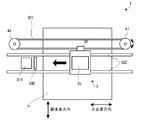
図25(b)は、キャリッジ軸622上をヘッドユニット708が移動しつつインク滴710をインク滴受け709に向けて吐出されちょうど検出領域707をインク滴710が通過する様子を示す図である。
インク滴710が上方から速度V1で吐出され、ヘッドユニット708が速度V2で移動していると、インク滴710はその合成速度(V1+V2)となり、検出領域707へ確実に通過させるにはかなりの精度が要求される。検出感度を高めようとすると、S1/S2を大きくする即ち検出領域707の面積S2を小さくすればよいが、そうするとインク滴710が検出領域707を通過する検出のタイミングを精度良くしなければならない。
【0008】
逆に、インク滴710が検出領域707を通過する検出のタイミングを緩やかにすれば、検出感度が低下してしまう。この課題を解決しようといくつかの提案がされている。
具体的には、例えば、インクジェットヘッドのインク吐出口の並び方向に対して、インク吐出を検出するフォトセンサの発光素子と受光素子とで決定される検出光軸を相対的に所定角度なすように配置し、フォトセンサによる検出範囲を広くする技術がある(特許文献1)。
【0009】
しかし、特許文献1に記載されている技術は、感度を低下させずに受光領域を斜めにインク滴が透過する分だけ検出タイミングが緩やかになるが、依然としてその改善効果は比較的小さい。また、インク滴が検出領域の対角線上を通過するように、インク吐出口と検出領域との位置関係を高精度に設定しなければ、逆に、検出範囲が狭くなりかねない。
また、別の検出方法として、インクに対する撥水性の高い反射板と、反射光量を検知するセンサとを有し、インク滴を吐出させ、反射板からの反射光量をセンサで検出して吐出インク滴の状態を検出する技術がある(特許文献2)。
【0010】
しかし、特許文献2に記載されている技術は、反射板に着弾したインク滴に浮遊する紙粉やゴミなどが付着すると、反射板の反射率が低下することもあるので、インク滴を反射板に着弾させるという手法では、長期間の使用を考慮すると、信頼性という点では課題がある。
さらに、インクタンク内のインク保持量をモニタするセンサとして圧電振動子を利用することが提案されている(特許文献3)。
【0011】
しかし、特許文献3に記載されている技術は、圧電振動子がインクタンク内にあり、実際にインクと接触している。圧電振動子とインクとの接触する部分の面積が変化すると圧電振動子の固有振動数もそれに連れて変化するという原理を使っており、圧電振動子を使う点が類似しているが、インク量の変化がミリリットルのレベルでないと検出できなかった。そのため、数ピコリットル〜100ピコリットルレベルのインク滴を吐出するインクジェットプリンタではインク滴の吐出異常を検出することができなかった。
【0012】
【特許文献1】
特開平9−94948号公報
【特許文献2】
特開平8−332736号公報
【特許文献3】
特開平7−137276号公報
【0013】
【発明が解決しようとする課題】
本発明の目的は、液滴吐出ヘッドの吐出ノズルと液滴検知部との位置関係を高精度に設定する必要がなく、長期間の使用に際しても高い信頼性を確保して吐出異常の有無を検出することができ、吐出される液滴の量が少量であっても吐出異常の有無を検出することができる液滴不吐出検出装置および液滴吐出装置を提供することにある。
【0014】
【課題を解決するための手段】
このような目的は、下記の本発明により達成される。
本発明の液滴不吐出検出装置は、液滴を吐出する液滴吐出ヘッドの吐出異常を検出する液滴不吐出検出装置であって、
電極が設けられた圧電部材を有し、所定の固有振動数で発振するセンサと、
前記センサを所定の固有振動数で発振させる駆動手段と、
前記センサが所定の固有振動数で発振している状態で、前記液滴吐出ヘッドが前記センサに向けて液滴を吐出する吐出動作を行った際に、前記センサの固有振動数または当該固有振動数に対応する物理量を検出し、その検出値に基づいて前記液滴吐出ヘッドの吐出異常の有無を検出する検出手段とを備えることを特徴とする。
【0015】
これにより、センサの略全体を、インク滴を含む液滴の検出領域とすることができ、センサの面積(検出領域)を所定の大きさに設定することにより、液滴吐出ヘッドの吐出ノズルとセンサとの位置関係を高精度に設定する必要がなく、このため、組み立て・製造が容易であり、また、長期間の使用に際しても高い信頼性を確保して吐出異常の有無を検出することができ、また、吐出される液滴の量が少量であってもそれを検出、すなわち、吐出異常の有無を検出することができる液滴不吐出検出装置を提供することができる。
【0016】
本発明の液滴不吐出検出装置では、前記圧電部材は、板状をなし、該圧電部材の両面に電極が設けられており、
前記検出手段は、前記検出値の変化に基づいて前記吐出異常の有無を検出するのが好ましい。
本発明の液滴不吐出検出装置では、前記駆動手段は、前記センサを所定の固有振動数で発振させ、該センサを含む発振回路を有し、
前記検出手段は、前記発振回路からの出力信号の所定時間内におけるパルス数を計数する計測手段を有するのが好ましい。
本発明の液滴不吐出検出装置では、前記センサの振動モードは、厚みすべり振動であるのが好ましい。
【0017】
本発明の液滴不吐出検出装置は、液滴を吐出する液滴吐出ヘッドの吐出異常を検出する液滴不吐出検出装置であって、
電極が設けられた圧電部材を有し、表面弾性波を伝播するセンサと、
前記センサを駆動し、該センサに表面弾性波を伝播させる駆動手段と、
前記センサが表面弾性波を伝播している状態で、前記液滴吐出ヘッドが前記センサに向けて液滴を吐出する吐出動作を行った際に、前記伝播した表面弾性波の振幅または当該振幅に対応する物理量を検出し、その検出値に基づいて前記液滴吐出ヘッドの吐出異常の有無を検出する検出手段とを備えることを特徴とする。
【0018】
これにより、液滴吐出ヘッドの吐出ノズルとセンサとの位置関係を高精度に設定する必要がなく、このため、組み立て・製造が容易であり、また、長期間の使用に際しても高い信頼性を確保して吐出異常の有無を検出することができ、また、吐出される液滴の量がさらに少ない量であってもそれを検出、すなわち、吐出異常の有無を検出することができる液滴不吐出検出装置を提供することができる。
【0019】
本発明の液滴不吐出検出装置では、前記圧電部材は、板状をなし、該圧電部材の一方の面の一端側に、1対の櫛歯状の第1の電極が設けられ、他端側に、1対の櫛歯状の第2の電極が設けられ、前記センサの前記第1の電極側から前記第2の電極側に表面弾性波が伝播するよう構成されており、
前記液滴吐出ヘッドが前記センサの前記第1の電極と前記第2の電極との間に向けて液滴を吐出する吐出動作を行った際に、前記検出手段は、前記第2の電極に伝播した表面弾性波の振幅または当該振幅に対応する物理量を検出し、その検出値の変化に基づいて前記吐出異常の有無を検出するのが好ましい。
【0020】
本発明の液滴不吐出検出装置では、前記駆動手段は、前記第1の電極側に接続された高周波発振回路を有し、
前記検出手段は、前記第2の電極側に接続されたベクトル電圧計を有するのが好ましい。
本発明の液滴不吐出検出装置では、前記センサは、前記電極を覆う保護膜を有するのが好ましい。
これにより、センサの電極を外気等から遮断することができるので、電極の腐食等を防止することができる。
【0021】
本発明の液滴不吐出検出装置では、前記センサ上に残留した液滴を除去する清掃手段をさらに備えるのが好ましい。
これにより、センサ上に残留した液滴を除去することができるので、吐出異常の有無をより確実に検出することができる。
本発明の液滴不吐出検出装置では、前記センサを覆う位置と覆わない位置とに相対的に移動可能に設置されたカバーをさらに備えるのが好ましい。
これにより、センサにゴミ等が付着するのを防止することができ、よって、ゴミ等の付着による誤検出をより確実に防止することができる。
【0022】
本発明の液滴吐出装置は、駆動回路によりアクチュエータを駆動して液体が充填されたキャビティ内の圧力を変化させることにより前記キャビティに連通するノズルから前記液体を液滴として吐出する液滴吐出ヘッドと、
本発明の液滴不吐出検出装置とを備えることを特徴とする。
これにより、液滴吐出ヘッドの吐出ノズルとセンサとの位置関係を高精度に設定する必要がなく、このため、組み立て・製造が容易であり、また、長期間の使用に際しても高い信頼性を確保して吐出異常の有無を検出することができ、また、吐出される液滴の量が少量であってもそれを検出、すなわち、吐出異常の有無を検出することができる液滴不吐出検出装置を備えた液滴吐出装置を提供することができる。
【0023】
本発明の液滴吐出装置では、前記液滴吐出ヘッドに対し、吐出異常の原因を解消させる回復処理を行う回復手段をさらに備え、
前記液滴不吐出検出装置によって吐出異常が検出された場合、前記回復手段による回復処理を行うのが好ましい。
これにより、吐出異常が生じた液滴吐出ヘッドを正常な状態に回復させることができるので、その後の印刷動作において吐出異常(ドット抜け)が発生するのを防止することができる。
【0024】
本発明の液滴吐出装置では、前記回復手段による回復処理を行った後、前記液滴不吐出検出装置による検出を再度行うのが好ましい。
これにより、回復処理によって、液滴吐出ヘッドの異常が解消されたかどうか(正常状態に回復したかどうか)を確認することができ、その後の印刷動作において吐出異常(ドット抜け)が発生するのをより確実に防止することができる。
【0025】
本発明の液滴吐出装置では、前記回復手段は、前記液滴吐出ヘッドのノズルが配列されるノズル面をワイパにより拭き取るワイピング処理を行うワイピング手段を含むのが好ましい。
これにより、液滴吐出ヘッドの吐出ノズルの出口に紙粉などの異物が付着した場合の吐出異常を回復させるのに好適な回復処理を行うことができる。
【0026】
本発明の液滴吐出装置では、前記回復手段は、前記液滴吐出ヘッドのノズル面を覆うキャップに接続するポンプによりポンプ吸引処理を行うポンピング手段を含むのが好ましい。
これにより、液滴吐出ヘッドの吐出ノズルが目詰まりした場合や、キャビティ内に気泡が混入した場合の吐出異常を回復させるのに好適な回復処理を行うことができる。
【0027】
本発明の液滴吐出装置では、前記センサを移動させる移動手段をさらに備えるのが好ましい。
これにより、いずれの位置においても液滴吐出ヘッドの吐出異常の検出を行うことができる。
本発明の液滴吐出装置では、前記液滴吐出装置は、インクジェットプリンタであるのが好ましい。
【0028】
【発明の実施の形態】
以下、図1〜図25を参照して本発明の液滴吐出装置の好適な実施形態を詳細に説明する。なお、この実施形態は例示として挙げるものであり、これにより本発明の内容を限定的に解釈すべきではない。なお、以下、本実施形態では、本発明の液滴吐出装置の一例として、インク(液状材料)を吐出して記録用紙(液滴受容物)に画像をプリントするインクジェットプリンタを用いて説明する。
【0029】
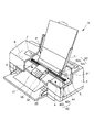
図1は、本発明の実施形態における液滴吐出装置の一種であるインクジェットプリンタ1の構成を示す概略図である。なお、以下の説明では、図1中、上側を「上部」、下側を「下部」という。まず、このインクジェットプリンタ1の構成について説明する。
図1に示すインクジェットプリンタ1は、装置本体2を備えており、上部後方に記録用紙Pを設置するトレイ21と、下部前方に記録用紙Pを排出する排紙口22と、上部面に操作パネル7とが設けられている。
【0030】
操作パネル7は、例えば、液晶ディスプレイ、有機ELディスプレイ、LEDランプ等で構成され、エラーメッセージ等を表示する表示部(図示せず)と、各種スイッチ等で構成される操作部(図示せず)とを備えている。この操作パネル7の表示部は、報知手段として機能する。
また、装置本体2の内部には、主に、往復動する印字手段(移動体)3を備える印刷装置(印刷手段)4と、記録用紙Pを印刷装置4に対し供給・排出する給紙装置(液滴受容物搬送手段)5と、印刷装置4および給紙装置5を制御する制御部(制御手段)6とを有している。
【0031】
制御部6の制御により、給紙装置5は、記録用紙Pを1枚ずつ間欠送りする。この記録用紙Pは、印字手段3の下部近傍を通過する。このとき、印字手段3が記録用紙Pの送り方向とほぼ直交する方向に往復移動して、記録用紙Pへの印刷が行われる。すなわち、印字手段3の往復動と記録用紙Pの間欠送りとが、印刷における主走査および副走査となって、インクジェット方式の印刷が行われる。印刷装置4は、印字手段3と、印字手段3を主走査方向に移動(往復動)させる駆動源となるキャリッジモータ41と、キャリッジモータ41の回転を受けて、印字手段3を往復動させる往復動機構42とを備えている。
【0032】
印字手段3は、複数のヘッドユニット35と、各ヘッドユニット35にインクを供給するインクカートリッジ(I/C)31と、各ヘッドユニット35およびインクカートリッジ31を搭載したキャリッジ32とを有している。なお、インクの消費量が多いインクジェットプリンタの場合には、インクカートリッジ31がキャリッジ32に搭載されず別な場所に設置され、チューブでヘッドユニット35と連通されインクが供給されるように構成してもよい(図示せず)。
【0033】
なお、インクカートリッジ31として、イエロー、シアン、マゼンタ、ブラック(黒)の4色のインクを充填したものを用いることにより、フルカラー印刷が可能となる。この場合、印字手段3には、各色にそれぞれ対応したヘッドユニット35(この構成については、後に詳述する。)が設けられることになる。ここで、図1では、4色のインクに対応した4つのインクカートリッジ31を示しているが、印字手段3は、その他の色、例えば、ライトシアン、ライトマゼンダ、ダークイエロー、特色インクなどのインクカートリッジ31をさらに備えるように構成されてもよい。
【0034】
往復動機構42は、その両端をフレーム(図示せず)に支持されたキャリッジガイド軸422と、キャリッジガイド軸422と平行に延在するタイミングベルト421とを有している。
キャリッジ32は、往復動機構42のキャリッジガイド軸422に往復動自在に支持されるとともに、タイミングベルト421の一部に固定されている。
【0035】
キャリッジモータ41の作動により、プーリを介してタイミングベルト421を正逆走行させると、キャリッジガイド軸422に案内されて、印字手段3が往復動する。そして、この往復動の際に、印刷されるイメージデータ(印刷データ)に対応して、ヘッドユニット35の各インクジェットヘッド100から適宜インク滴が吐出され、記録用紙Pへの印刷が行われる。
【0036】
給紙装置5は、その駆動源となる給紙モータ(M)51と、給紙モータ51の作動により回転する給紙ローラ52とを有している。
給紙ローラ52は、記録用紙Pの搬送経路(記録用紙P)を挟んで上下に対向する従動ローラ52aと駆動ローラ52bとで構成され、駆動ローラ52bは給紙モータ51に連結されている。これにより、給紙ローラ52は、トレイ21に設置した多数枚の記録用紙Pを、印刷装置4に向かって1枚ずつ送り込んだり印刷装置4から1枚ずつ排出したりするようになっている。なお、トレイ21に代えて、記録用紙Pを収容する給紙カセットを着脱自在に装着し得るような構成であってもよい。
【0037】
さらに給紙モータ51は、印字手段3の往復動作と連動して、画像の解像度に応じて、記録用紙Pの紙送りも行う。給紙動作と紙送り動作については、それぞれ別のモータで行うことも可能であり、また、電磁クラッチなどのトルク伝達の切り替えを行う部品によって同じモータで行うことも可能である。
制御部6は、例えば、パーソナルコンピュータ(PC)やディジタルカメラ(DC)等のホストコンピュータ8から入力された印刷データに基づいて、印刷装置4や給紙装置5等を制御することにより記録用紙Pに印刷処理を行うものである。また、制御部6は、操作パネル7の表示部にエラーメッセージ等を表示させ、あるいはLEDランプ等を点灯/点滅させるとともに、操作部から入力された各種スイッチの押下信号に基づいて、対応する処理を各部に実行させるものである。さらに、制御部6は、必要に応じてエラーメッセージや吐出異常などの情報をホストコンピュータ8(図2)に転送することもある。
【0038】
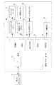
図2は、本発明のインクジェットプリンタの主要部を概略的に示すブロック図である。この図2において、本発明のインクジェットプリンタ1は、ホストコンピュータ8から入力された印刷データなどを受け取るインターフェース部(IF:Interface)9と、制御部6と、キャリッジモータ41と、キャリッジモータ41を駆動制御するキャリッジモータドライバ43と、給紙モータ51と、給紙モータ51を駆動制御する給紙モータドライバ53と、ヘッドユニット35と、ヘッドユニット35を駆動制御するヘッドドライバ33と、回復手段24と、操作パネル7とを備える。なお、回復手段24については、詳細を後述する。
【0039】
この図2において、制御部6は、ヘッドユニット35の各インクジェットヘッド100に対し印刷処理やセンサ500(図7参照)に液滴を吐出するように命令するなどの各種処理を実行するCPU(Central Processing Unit)61と、ホストコンピュータ8からIF9を介して入力される印刷データを図示しないデータ格納領域に格納する不揮発性半導体メモリの一種であるEEPROM(Electrically Erasable Programmable Read−Only Memory)62と、CPU61が種々の命令を行うデータを含む各種データを一時的に格納し、あるいは印刷処理などのアプリケーションプログラムを一時的に展開するRAM(Random Access Memory)63と、各部を制御する制御プログラム等を格納する不揮発性半導体メモリの一種であるPROM64とを備えている。なお、制御部6の各構成要素は、図示しないバスを介して電気的に接続されている。
【0040】
上述のように、印字手段3は、各色のインクに対応した複数のヘッドユニット35を備える。また、各ヘッドユニット35は、複数のノズル110(図3)と、これらの各ノズル110にそれぞれ対応する静電アクチュエータ120(図3)とを備える。すなわち、ヘッドユニット35は、1組のノズル110および静電アクチュエータ120を有してなるインクジェットヘッド100(液滴吐出ヘッド)を複数個備えた構成になっている。そして、ヘッドドライバ33は、各インクジェットヘッド100の静電アクチュエータ120を駆動して、インクの吐出タイミングを制御する駆動回路(図示せず)を有している。なお、静電アクチュエータ120の構成については後述する。
【0041】
また、制御部6には、図示しないが、例えば、インクカートリッジ31のインク残量、印字手段3の位置、温度、湿度等の印刷環境等を検出可能な各種センサが、それぞれ電気的に接続されている。
制御部6は、IF9を介して、ホストコンピュータ8から印刷データを入手すると、その印刷データをEEPROM62に格納する。そして、CPU61は、この印刷データに所定の処理を実行して、この処理データおよび各種センサからの入力データに基づいて、各ドライバ33、43、53に駆動信号を出力する。各ドライバ33、43、53を介してこれらの駆動信号が入力されると、ヘッドユニット35の複数の静電アクチュエータ120、印刷装置4のキャリッジモータ41および給紙装置5がそれぞれ作動する。これにより、記録用紙Pに印刷処理が実行される。
【0042】
つぎに、印字手段3内の各ヘッドユニット35の構造を説明する。図3は、図1に示すヘッドユニット35(インクジェットヘッド100)の概略的な断面図であり、図4は、1色のインクに対応するヘッドユニット35の概略的な構成を示す分解斜視図であり、図5は、図3および図4に示すヘッドユニット35を適用した印字手段3のノズル面の一例を示す平面図である。なお、図3および図4は、通常使用される状態とは上下逆に示されている。
【0043】
図3に示すように、ヘッドユニット35は、インク取入れ口131、ダンパ室130およびインク供給チューブ311を介して、インクカートリッジ31に接続されている。ここで、ダンパ室130は、ゴムからなるダンパ132を備えている。このダンパ室130により、キャリッジ32が往復走行する際のインクの揺れおよびインク圧の変化を吸収することができ、これにより、ヘッドユニット35に所定量のインクを安定的に供給することができる。
【0044】
また、ヘッドユニット35は、シリコン基板140を挟んで、上側に同じくシリコン製のノズルプレート150と、下側にシリコンと熱膨張率が近いホウ珪酸ガラス基板(ガラス基板)160とがそれぞれ積層された3層構造をなしている。中央のシリコン基板140には、独立した複数のキャビティ(圧力室)141(図4では、7つのキャビティを示す)と、一つのリザーバ(共通インク室)143と、このリザーバ143を各キャビティ141に連通させるインク供給口(オリフィス)142としてそれぞれ機能する溝が形成されている。各溝は、例えば、シリコン基板140の表面からエッチング処理を施すことにより形成することができる。このノズルプレート150と、シリコン基板140と、ガラス基板160とがこの順序で接合され、各キャビティ141、リザーバ143、各インク供給口142が区画形成されている。
【0045】
これらのキャビティ141は、それぞれ短冊状(直方体状)に形成されており、後述する振動板121の振動(変位)によりその容積が可変であり、この容積変化によりノズル110からインク(液状材料)を吐出するよう構成されている。ノズルプレート150には、各キャビティ141の先端側の部分に対応する位置に、ノズル110が形成されており、これらが各キャビティ141に連通している。また、リザーバ143が位置しているガラス基板160の部分には、リザーバ143に連通するインク取入れ口131が形成されている。インクは、インクカートリッジ31からインク供給チューブ311、ダンパ室130を経てインク取入れ口131を通り、リザーバ143に供給される。リザーバ143に供給されたインクは、各インク供給口142を通って、独立した各キャビティ141に供給される。なお、各キャビティ141は、ノズルプレート150と、側壁(隔壁)144と、底壁121とによって、区画形成されている。
【0046】
独立した各キャビティ141は、その底壁121が薄肉に形成されており、底壁121は、その面外方向(厚さ方向)、すなわち、図3において上下方向に弾性変形(弾性変位)可能な振動板(ダイヤフラム)として機能するように構成されている。したがって、この底壁121の部分を、以後の説明の都合上、振動板121と称して説明することもある(すなわち、以下、「底壁」と「振動板」のいずれにも符号121を用いる)。
【0047】
ガラス基板160のシリコン基板140側の表面には、シリコン基板140の各キャビティ141に対応した位置に、それぞれ、浅い凹部161が形成されている。したがって、各キャビティ141の底壁121は、凹部161が形成されたガラス基板160の対向壁162の表面に、所定の間隙を介して対峙している。すなわち、キャビティ141の底壁121と後述するセグメント電極122の間には、所定の厚さ(例えば、0.2ミクロン程度)の空隙が存在する。なお、前記凹部161は、例えば、エッチングなどで形成することができる。
【0048】
ここで、各キャビティ141の底壁(振動板)121は、ヘッドドライバ33から供給される駆動信号によってそれぞれ電荷を蓄えるための各キャビティ141側の共通電極124の一部を構成している。すなわち、各キャビティ141の振動板121は、それぞれ、後述する対応する静電アクチュエータ120の対向電極(コンデンサの対向電極)の一方を兼ねている。そして、ガラス基板160の凹部161の表面には、各キャビティ141の底壁121に対峙するように、それぞれ、共通電極124に対向する電極であるセグメント電極122が形成されている。また、図3に示すように、各キャビティ141の底壁121の表面は、シリコンの酸化膜(SiO2)からなる絶縁層123により覆われている。このように、各キャビティ141の底壁121、すなわち、振動板121と、それに対応する各セグメント電極122とは、キャビティ141の底壁121の図3中下側の表面に形成された絶縁層123と凹部161内の空隙とを介し、対向電極(コンデンサの対向電極)を形成
(構成)している。したがって、振動板121と、セグメント電極122と、これらの間の絶縁層123および空隙とにより、静電アクチュエータ120の主要部が構成される。
【0049】
図3に示すように、これらの対向電極の間に駆動電圧を印加するための駆動回路(図示せず)を含むヘッドドライバ33は、制御部6から入力される印字信号(印字データ)に応じて、これらの対向電極間の充放電を行う。ヘッドドライバ(電圧印加手段)33の一方の出力端子は、個々のセグメント電極122に接続され、他方の出力端子は、シリコン基板140に形成された共通電極124の入力端子124aに接続されている。なお、シリコン基板140には不純物が注入されており、それ自体が導電性をもつために、この共通電極124の入力端子124aから底壁121の共通電極124に電圧を供給することができる。また、例えば、シリコン基板140の一方の面に金や銅などの導電性材料の薄膜を形成してもよい。これにより、低い電気抵抗で(効率良く)共通電極124に電圧(電荷)を供給することができる。この薄膜は、例えば、蒸着あるいはスパッタリング等によって形成すればよい。ここで、本実施形態では、例えば、シリコン基板140とガラス基板160とを陽極接合によって結合(接合)させるので、その陽極結合において電極として用いる導電膜をシリコン基板140の流路形成面側(図3に示すシリコン基板140の上部側)に形成している。そして、この導電膜をそのまま共通電極124の入力端子124aとして用いる。なお、本実施形態では、例えば、共通電極124の入力端子124aを省略してもよく、また、シリコン基板140とガラス基板160との接合方法は、陽極接合に限定されない。
【0050】
図4に示すように、ヘッドユニット35は、複数のノズル110が形成されたノズルプレート150と、複数のキャビティ141、複数のインク供給口142、一つのリザーバ143が形成されたシリコン基板140と、絶縁層123とを備え、これらがガラス基板160を含む基体170に収納されている。基体170は、例えば、各種樹脂材料、各種金属材料等で構成されており、この基体170にシリコン基板140が固定、支持されている。
【0051】
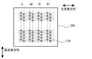
なお、ノズルプレート150に形成されたノズル110は、図4では簡潔に示すためにリザーバ143に対して略並行に直線的に配列されているが、ノズルの配列パターンはこの構成に限らず、通常は、例えば、図5に示すノズル配置パターンのように、段をずらして配置される。また、このノズル110間のピッチは、印刷解像度(dpi:dot per inch)に応じて適宜設定され得るものである。なお、図5では、4色のインク(インクカートリッジ31)を適用した場合におけるノズル110の配置パターンを示している。
【0052】
図6は、図3のIII−III断面の駆動信号入力時の各状態を示す。ヘッドドライバ33から対向電極間に駆動電圧が印加されると、対向電極間にクーロン力が発生し、底壁(振動板)121は、初期状態(図6(a))に対して、セグメント電極122側へ撓み、キャビティ141の容積が拡大する(図6(b))。この状態において、ヘッドドライバ33の制御により、対向電極間の電荷を急激に放電させると、振動板121は、その弾性復元力によって図中上方に復元し、初期状態における振動板121の位置を越えて上部に移動し、キャビティ141の容積が急激に収縮する(図2(c))。このときキャビティ141内に発生する圧縮圧力により、キャビティ141を満たすインク(液状材料)の一部が、このキャビティ141に連通しているノズル110からインク滴として吐出される。
【0053】
さて、ヘッドユニット35の各インクジェットヘッド100では、前述したような吐出動作を行ったにもかかわらずノズル110からインク滴が正常に吐出されない現象、すなわち液滴の吐出異常が発生する場合がある。この吐出異常が発生する原因としては、例えば、(1)キャビティ141内への気泡の混入、(2)ノズル110付近でのインクの乾燥・増粘(固着)、(3)ノズル110出口付近への紙粉付着、等が挙げられる。
【0054】
この吐出異常が発生すると、その結果としては、典型的にはノズル110から液滴が吐出されないこと、すなわち液滴の不吐出現象が現れ、その場合、記録用紙Pに印刷(描画)した画像における画素のドット抜けを生じる。また、吐出異常の場合には、ノズル110から液滴が吐出されたとしても、液滴の量が過少であったり、その液滴の飛行方向(弾道)がずれたりして適正に着弾しないので、やはり画素のドット抜けとなって現れる。
【0055】
そして、このようなインクジェットプリンタ1は、ヘッドユニット35(各インクジェットヘッド100)の吐出異常の有無、すなわちヘッドユニット35(各インクジェットヘッド100)からインク滴510が正常に吐出されるかどうかを検出する、図9に示す後述する液滴不吐出検出装置50を備えている。
【0056】
次に、液滴不吐出検出装置50について説明する。
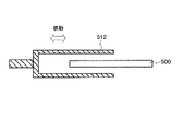
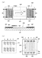
図7(a)は、図1に示すインクジェットプリンタ1が備える液滴不吐出検出装置50のセンサ500の構成を示す平面図、背面図および断面側面図、図7(b)は、センサ500の他の例を示す平面図および背面図、図7(c)は、図7(a)に示すセンサ500の周辺を示す側面図、図8は、図7(a)に示すセンサ500を覆うカバー512を示す断面図、図9(a)は、図1に示すインクジェットプリンタ1が備える液滴不吐出検出装置50の構成を示すブロック図である。
【0057】
なお、図7(a)の平面図および背面図、図7(b)の平面図および背面図では、保護膜を図示せず、また、電極および配線に斜線を付した。
液滴不吐出検出装置50は、図7(a)に示すセンサ500を有している。まず、このセンサ500の構成について説明する。
図7(a)に示すように、センサ500は、圧電材料で形成された板状の圧電部材(圧電素子)501と、この圧電部材501の一方の面(表面)に設けられた電極502と、他方の面(裏面)に設けられた電極503とを有している。
【0058】
これらの電極502および503上には、それぞれ、保護膜504および505が設けられ、各電極502および503は、それぞれ、保護膜504および505で覆われている。この保護膜504および505により、電極502および503の腐食等を防止することができ、高い信頼性が得られる。
なお、保護膜504および505を省略してもよいことは、言うまでもない。
【0059】
このセンサ500(圧電部材501)の平面視での形状は、本実施形態では、図7(a)に示すように、略長方形をなしている。この液滴不吐出検出装置50では、センサ500(長方形)の一部または全部が検出領域となり、この検出領域にインク滴510が付着(着弾)した場合、それを検出することができる。
検出領域の広さは、特に限定されないが、例えば、ヘッドユニット35におけるノズル110が配列されている領域の面積より少し大きい程度とすることができる。これにより、ヘッドユニット35をセンサ500に対し静止したまま、各インクジェットヘッド100について吐出異常の有無の検出を行うことができる。
【0060】
このセンサ500は、例えば、ヘッドユニット35のノズルプレート150(ノズル面)に対して略平行になるように、所定の位置に固定的に設置、または、移動可能に設置される。
なお、本発明では、センサ500(圧電部材501)の形状は、特に限定されず、例えば、その平面視での形状は、図7(b)に示すように略円形であってもよく、また、この他の形状であってもよい。
【0061】
また、使用する圧電材料としては、特に限定されず、例えば、水晶(SiO2)、タンタル酸リチウム(LiTaO3)、ランガサイト(La3Ga5SiO14)、ニオブ酸カリウム(KNbO3)、ニオブ酸リチウム(LiNbO3)、酸化亜鉛(ZnO)、ポリ弗化ビニリデン(PVDF)、ペロブスカイト型結晶構造をしている強誘電体のチタン酸バリウム(BaTiO3)、チタン酸鉛(PbTiO3)、チタン酸ジルコン酸鉛(PZT)に少量のLaを添加して得られるチタン酸ジルコン酸ランタン鉛(PLZT)等の各種のものを用いることができる。
【0062】
また、保護膜504および505の構成材料としては、それぞれ、特に限定されず、例えば、酸化シリコン(SiO2)のような酸化物や窒化物、またはポリイミド、感光性フォトレジスト等を用いることができる。
ここで、このセンサ500のような圧電材料で形成された圧電部材501を利用した振動子では、圧電部材501の振動モードによって、固有振動数(発振周波数)の範囲がおおよそ決まる。すなわち、その固有振動数は、厚みすべり振動では、例えば、1〜10MHz程度、とじ込め振動では、例えば、2〜100MHz程度、表面弾性波では、例えば、10〜1000MHz程度となる。
このセンサ500の振動モードは、厚みすべり振動であり、電極502、503間に所定の周波数の交流電圧を印加すると、圧電部材501、すなわち、センサ500は、その厚み方向に固有振動数で振動(発振)する。
【0063】
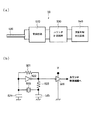
図9(a)に示すように、液滴不吐出検出装置50は、センサ500を所定の固有振動数で発振させ、そのセンサ500を含む発振回路(駆動手段)520と、この発振回路520の出力側に設けられたカウンタ計測回路(計測手段)530と、このカウンタ計測回路530の出力側に設けられた演算処理判定回路(判定手段)540とを有している。カウンタ計測回路530および演算処理判定回路540により、インクジェットヘッド(液滴吐出ヘッド)100の吐出異常の有無を検出(判定)する検出手段の主要部が構成される。なお、これら発振回路520、カウンタ計測回路530および演算処理判定回路540は、前述した制御部6により制御される。
【0064】
次に、液滴不吐出検出装置50によるインクジェットヘッド(液滴吐出ヘッド)100の吐出異常の検出の原理(方法)について説明する。
まず、センサ500を用いて図9(b)のコルピッツ型発振回路にすると、センサ500はその厚み方向に固有振動数で振動する。この時、基本的には1次の厚みすべり振動が生じるが、ある条件を満たすと3次の厚みすべり振動へ遷移する。
【0065】
次に、ヘッドユニット35(各インクジェットヘッド100)は、制御部6からの命令に基づき、センサ500に向けてインク滴510を吐出するべく、吐出動作を行う。
この状態で、センサ500の表面にインク滴510が付着すると、センサ500は、そのインク滴510の質量分だけ重くなり、これにより、センサ500の固有振動数は、小さくなる(変化する)。
【0066】
この液滴不吐出検出装置50では、前記センサ500の固有振動数の減少(変化)を捉えて、インクジェットヘッド100からインク滴510が吐出されたか否か(センサ500の表面にインク滴510が付着したか否か)を判別し、インクジェットヘッド100の吐出異常の有無を検出する。
すなわち、液滴不吐出検出装置50は、インクジェットヘッド100がセンサ500に向けてインク滴510を吐出する吐出動作を行った際に、センサ500の固有振動数または当該固有振動数に対応する物理量を検出し、その検出値に基づいて、インクジェットヘッド100の吐出異常の有無を検出する。この場合、検出値が吐出動作の前後で減少(変化)した場合には、センサ500の表面にインク滴510が付着し、インクジェットヘッド100の吐出異常は無し(正常)と判定し、検出値が吐出動作の前後で変化しない場合には、センサ500の表面にインク滴510が付着せず、インクジェットヘッド100の吐出異常と判定する。
【0067】
前記固有振動数に対応する物理量としては、例えば、所定時間内におけるセンサ500の振動の数(回数)、振動の周期、振動の周期のN倍(但し、Nは、2以上の整数)、振動の半周期、振動の半周期のM倍(Mは、3以上の奇数)等が挙げられる。
ここで、センサ500の厚み方向に振動する振動モードでは、センサ500の発振周波数(固有振動数)f0は、圧電部材501の材質、形状から決まる定数N、センサの厚さtによって、
f0=N/t
と表される。
【0068】
インク滴510がセンサ500に付着したときに変化する周波数(振動数)は、センサ500の厚さがΔtだけ厚くなったとして計算できる。センサ500の比重をρ1、付着したインク滴510の比重をρ2、付着したインク滴510の体積をv2、付着したインク滴510がセンサ500全面に付着したと想定したインク滴510の面積をS2とすれば、Δtは、
Δt=(ρ2・v2)/(ρ1・S2)
と表される。
この厚み変化Δtにより、インク滴510が付着した後のセンサ500の発振周波数(固有振動数)fは、
f=N/(t+Δt)
となる。
【0069】
図9(b)は、図9(a)に示す発振回路520の構成例を示す回路図である。
図9(b)に示す発振回路520は、センサ500を含むコルピッツ型発振回路であり、インバータ522に対して、センサ500と、コンデンサ524、525とからなるLC並列共振回路と、抵抗(負荷抵抗)521、523と、インバータ526とを接続することによって構成されている。
【0070】
前述したように、センサ500にインク滴510が付着し、センサ500の固有振動数が減少(変化)すると、LC並列共振回路から反転増幅器に入力される信号の周波数が減少し、インバータ526の出力端子から出力される信号、すなわち、発振回路520の出力信号の発振周波数が減少する。
従って、この発振回路520の出力信号に基づいて、インクジェットヘッド100の吐出異常の有無を検出することができる。
なお、ここでは、発振回路520として、コルピッツ型発振回路を一例として示したが、他の形態のものとしてもよい。
【0071】
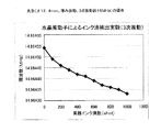
図10は、センサ500に付着したインク滴510の数(累積インク滴数)と、センサ500の1次振動の周波数との関係を示すグラフである。なお、横軸にインク滴510の数を示し、縦軸に周波数を示す。
具体的には、図7(b)に示す円形の水晶振動子であって、外径12.4mm、振動モードが厚みすべり振動、1次振動が約5MHzの水晶振動子に対して、ヘッドユニット35のインクジェットヘッド100からインク滴510を100ショットずつ合計1000ショット滴下し、水晶振動子の発振周波数を順次測定した。
測定結果は、図10のグラフに示す通りである。
【0072】
図11は、センサ500に付着したインク滴510の数(累積インク滴数)と、センサ500の3次振動の周波数との関係を示すグラフである。なお、横軸にインク滴510の数を示し、縦軸に周波数を示す。
具体的には、図7(b)に示す円形の水晶振動子であって、外径12.4mm、振動モードが厚みすべり振動、3次振動が約15MHzの水晶振動子に対して、ヘッドユニット35のインクジェットヘッド100からインク滴510を100ショットずつ合計1000ショット滴下し、水晶振動子の発振周波数を順次測定した。
測定結果は、図11のグラフに示す通りである。
【0073】
上記各測定結果から判るように、センサ500に付着したインク滴510の数(体積)が増加すると、水晶振動子の発振周波数は、それに応じて減少し、従って、インク滴510のサイズが変わっても、インク滴がセンサ500に付着した場合と、インク滴がセンサ500に付着しない場合とで、それに応じた周波数変化をすることが判る。
【0074】
ここで、本実施形態の液滴不吐出検出装置50において設定されるセンサ500の固有振動数は、振動モードが厚みすべり振動であれば、特に限定されないが、4〜64MHzの範囲で出来るだけ高い振動数であるのが好ましい。
これにより、高い感度が得られ、インク滴510をより確実に検出することができ、インクジェットヘッド100の吐出異常の有無をより確実に検出することができ、また、量産にも有利である。
液滴不吐出検出装置50は、さらに、センサ500上に残留したインク滴を除去する(センサ500上を清掃する)清掃手段550を有している。
図12は、清掃手段550の構成を示す側面図である。
【0075】
同図に示すように、清掃手段550は、後述する回復手段24のワイパ300のような部材で構成される。すなわち、清掃手段550は、例えば、ヘッドユニット35のノズルプレート150(ノズル面)と、センサ500上面との間の間隔よりもやや長い丈の弾性変形可能な板状の部材(例えば、ゴム部材)である。
この清掃手段550は、ヘッドユニット35のノズルプレート150の端部に取り付けられている(固定されている)。このため、インクジェットヘッド100の吐出異常の検出の際は、その清掃手段550が邪魔になることはない。
【0076】
ヘッドユニット35がキャリッジ軸422に沿って主走査方向に移動すると、清掃手段550は、そのヘッドユニット35と一体的に移動する。そして、清掃手段550が、センサ500上を移動する際、センサ500の上面を撫で、これにより、センサ500上に残留したインク滴510’が除去される。すなわち、センサ500の表面が清掃される。
【0077】
なお、清掃手段550によりセンサ500の清掃を行うタイミングや回数等は、諸条件に応じて適宜設定される。
この液滴不吐出検出装置50では、前記清掃手段550により、センサ500上に残留した液滴を除去することができるので、吐出異常の有無をより確実に検出することができる。
【0078】
なお、清掃手段550は、これに限定されず、例えば、センサ500側に設けられ、センサ500上面を撫でるように移動可能なワイパを有するワイパ機構であってもよい。
また、本実施形態のインクジェットプリンタ1は、センサ500を移動させる図示しない移動手段を有している。これにより、液滴不吐出検出装置50では、センサ500を図7(c)の紙面に垂直な方向に移動可能になっている。この移動手段の作動により、インクジェットプリンタ1では、ヘッドユニット35(インクジェットヘッド100)の吐出異常の検出を行うときには、例えば、ヘッドユニット35(インクジェットヘッド100)と、後述するキャップ310との間にセンサ500を挿入(移動)する(図7(c)に示す状態)。そして、吐出異常の検出を行わないとき(印刷時や、キャップ310を用いたポンプ吸引時など)には、ヘッドユニット35(インクジェットヘッド100)とキャップ310との間からセンサ500を退避させる。なお、センサ500は、所定の位置に、固定的に設置されていてもよい。
【0079】
また、図8に示すように、本実施形態の液滴不吐出検出装置50は、センサ500を覆う位置と覆わない位置とに相対的に移動可能に設置されたカバー512をさらに備えている。吐出異常の有無の検出を行わないときには、センサ500は、このカバー512に覆われている。これにより、センサ500の各部にゴミ、紙粉、インクミスト等が付着するのを防止することができ、例えば、感度が低下したりするような事態を回避できるので、インクジェットプリンタ1の長期間の使用後でも、液滴不吐出検出装置50の信頼性を維持することができる。
このカバー512は、図示しないカバー移動手段によって移動することにより、センサ500を覆う位置と覆わない位置とに移動する。あるいは、カバー512を固定とし、センサ500が移動するのに伴って、センサ500がカバー512内から出たり入ったりするようになっていてもよい。
【0080】
次に、液滴不吐出検出装置50の動作について説明する。
ヘッドユニット35(各インクジェットヘッド100)の吐出異常の有無を検出する際には、制御部6は、ヘッドユニット35が例えばホームポジションのように液滴不吐出検出装置50の作動可能位置にあるか否かを判定し、作動可能位置に位置していない場合には、キャリッジガイド軸422によってガイドしながら、ヘッドユニット35を作動可能位置(例えば、ホームポジション)に移動させる。
【0081】
次いで、制御部6は、図示しない移動手段によって、センサ500を、ヘッドユニット35の下側、図7(c)に示す例では、ヘッドユニット35とキャップ310との間に移動する。
次いで、制御部6は、発振回路520を駆動する。これにより、センサ500は、その厚み方向に固有振動数で振動(発振)し、発振回路520からの出力信号は、カウンタ計測回路530へ入力される。
【0082】
次いで、カウンタ計測回路530は、発振回路520からの出力信号の計測ゲート時間内におけるパルス数(波数)を計数(計測)する。この計測ゲート時間内における計数値(計測結果)は、センサ500の発振周波数(固有振動数)に対応する物理量である。
ここで、前記「パルス」には、波形整形された矩形波のみならず、例えば、発振回路520から出力された信号(出力信号)そのもの等も含まれる。
【0083】
また、後述する処理では、前記計数値をそのまま用いてもよく、また、計数値からセンサ500の発振周波数を算出し(求め)、その算出値を用いてもよい。
また、前記計測ゲート時間は、特に限定されず、例えば、その計測ゲート時間の調整により、前記カウンタ計測回路530での計数値がセンサ500の発振周波数となるようにすることもできる。
【0084】
カウンタ計測回路530での計測結果は、演算処理判定回路540へ入力され、演算処理判定回路540は、その計測結果を、吐出動作前のセンサ500の固有振動数または固有振動数に対応する物理量(以下、単に「固有振動数」と言う)として、図示しないメモリ(記憶手段)に記憶する。
この状態で、制御部6からヘッドユニット35のインクジェットヘッド100にインク滴510の吐出命令がされると、命令されたインクジェットヘッド100は吐出動作を行い、ノズル詰まり等の吐出異常がなければ、ノズル110から所定量のインク滴510が吐出され、そのインク滴510は、センサ500の表面に付着する。
【0085】
次いで、カウンタ計測回路530は、発振回路520からの出力信号の計測ゲート時間内におけるパルス数(波数)を計数(計測)する。
カウンタ計測回路530での計測結果は、演算処理判定回路540へ入力され、演算処理判定回路540は、その計測結果を、吐出動作後のセンサ500の固有振動数として、図示しないメモリに記憶する。
【0086】
このようにインク滴510がセンサ500の表面に付着した場合は、前述したように、センサ500の固有振動数は、小さくなる。このため、演算処理判定回路540は、メモリに記憶されている吐出動作前のセンサ500の固有振動数と、吐出動作後のセンサ500の固有振動数とに基づいて、ノズル110から所定量のインク滴510が吐出されているということを検出(判定)することができる。この検出は、例えば、下記のように行うことができる。
【0087】
演算処理判定回路540は、メモリに記憶されている吐出動作前のセンサ500の固有振動数と、吐出動作後のセンサ500の固有振動数とを比較して、これらの偏差(差)を求め、この偏差が、予め設定されている所定の閾値を超えたことを条件として、ノズル110から所定量のインク滴510が吐出されているということを検出する。
【0088】
一方、制御部6からインクジェットヘッド100に対してインク滴510の吐出命令がされたときに、当該インクジェットヘッド100に異常があると、ノズル110から所定量のインク滴510が吐出されず、センサ500の表面には、インク滴510が付着しない。
この場合には、前述したように、センサ500の固有振動数は、吐出動作の前後で変化しない(維持される)。このため、演算処理判定回路540は、メモリに記憶されている吐出動作前のセンサ500の固有振動数と、吐出動作後のセンサ500の固有振動数とに基づいて、ノズル110から所定量のインク滴510が吐出されているということを検出(判定)することができる。
【0089】
例えば、演算処理判定回路540は、メモリに記憶されている吐出動作前のセンサ500の固有振動数と、吐出動作後のセンサ500の固有振動数とを比較して、これらの偏差を求め、この偏差が、前記閾値以下であることを条件として、ノズル110から所定量のインク滴510が吐出されていないということを検出する。
このようにして、液滴不吐出検出装置50は、ヘッドユニット35の各インクジェットヘッド100について、吐出異常の有無を検出することができる。
【0090】
以上説明したように、この液滴不吐出検出装置50によれば、センサ500の略全体を、インク滴510の検出領域とすることができ、その検出領域を広くすることができる。このため、ヘッドユニット35(各インクジェットヘッド100)のノズル110と、検出領域との位置関係を高精度に設定(制御)する必要がない、という利点がある。よって、インクジェットプリンタ1は、液滴不吐出検出装置50に関連して、高い組み立て精度や位置精度を要求されないので、容易に組み立て・製造を行うことができ、また、液滴不吐出検出装置50は、長期間の使用に際しても高い信頼性を維持することができる。
【0091】
また、検出領域を容易に広くすることができ、その検出領域の広さを、例えば、ヘッドユニット35におけるノズル110が配列されている領域の面積より少し大きい程度とすることにより、ヘッドユニット35をセンサ500に対し静止したまま、各インクジェットヘッド100について吐出異常の有無の検出を行うことができる。
また、センサ500の構成が簡易であるとともに、吐出されるインク滴510の量が少量であってもそれを検出、すなわち、インクジェットヘッド100の吐出異常の有無を検出することができる。
【0092】
図13(a)は、本発明の液滴不吐出検出装置の他の実施形態におけるセンサを示す平面図および断面側面図、図13(b)は、図5に示すノズルプレート150に対応するセンサ600の構成例を模式的に示す平面図、図14は、本発明の液滴不吐出検出装置の他の実施形態の主腰部を模式的に示す図(一部ブロック図)である。
【0093】
なお、図13(a)の平面図では、保護膜を図示せず(保護膜と圧電部材との境界線のみを図示)、また、櫛歯状電極に斜線を付した。
以下、これらの図に基づいて本発明の液滴不吐出検出装置の他の実施形態について説明するが、前記図7および図9の液滴不吐出検出装置50との相違点を中心に説明し、同様の事項はその説明を省略する。
【0094】
液滴不吐出検出装置60は、図13(a)に示すセンサ600を有している。まず、このセンサ600の構成について説明する。
図13(a)に示すように、センサ600は、圧電材料で形成された板状の圧電部材(圧電素子)601と、この圧電部材601の一方の面に設けられた1対の櫛歯状の第1の電極(櫛歯状電極)602および1対の櫛歯状の第2の電極(櫛歯状電極)603とを有している。以下、櫛歯状の第1の電極および第2の電極を、それぞれ、単に「櫛歯状電極」と言う。なお、1対の櫛歯状電極は、IDT(Interdigital Transducer)とも呼ばれている。
【0095】
1対の櫛歯状電極602は、入力用であり、圧電部材601の一方の面の一端側に配置され、1対の櫛歯状電極603は、出力用であり、圧電部材601の一方の面の他端側に配置されている。
このセンサ600の振動モードは、表面弾性波であり、1対の櫛歯状電極602間に所定の周波数の交流電圧を印加(入力)すると、圧電部材601に表面弾性波が励振される。この表面弾性波は、圧電部材601の表面を櫛歯状電極602側から櫛歯状電極603側に伝播し、1対の櫛歯状電極603間に、その伝播した表面弾性波に対応する交流電圧が発生する(出力される)。
【0096】
また、これらの櫛歯状電極602および603上には、それぞれ、保護膜606および607が設けられ、各櫛歯状電極602および603は、それぞれ、保護膜606および607で覆われている。なお、保護膜606および607を省略してもよいことは、言うまでもない。
また、センサ600(圧電部材601)の平面視での形状は、本実施形態では、略長方形をなしているが、これに限定されず、他の形状であってもよい。
【0097】
この液滴不吐出検出装置60では、センサ600の櫛歯状電極602(保護膜606)と櫛歯状電極603(保護膜607)との間の領域(表面弾性波608の伝播する領域)の一部または全部が検出領域609となり、この検出領域609にインク滴510が付着(着弾)した場合、それを検出することができる。
また、設定されるセンサ600の固有振動数は、振動モードが表面弾性波であれば、特に限定されないが、106.25MHz〜1.25GHzの範囲で出来るだけ高い振動数であるのが好ましい。
これにより、より高い感度が得られ、インク滴510をより確実に検出することができ、インクジェットヘッド100の吐出異常の有無をより確実に検出することができる。
【0098】
図14に示すように、液滴不吐出検出装置60は、センサ600を所定の固有振動数で発振させ(駆動し)、センサ600に表面弾性波を伝播させる高周波発振回路である高周波発振器(駆動手段)610と、ベクトル電圧計620とを有している。
センサ600の1対の櫛歯状電極602は、入力信号線604を介して、高周波発振器610の出力側に接続されている。また、センサ600の1対の櫛歯状電極603は、出力信号線605を介して、ベクトル電圧計620の入力側に接続されている。
なお、本実施形態では、前記制御部6およびベクトル電圧計620が、インクジェットヘッド(液滴吐出ヘッド)100の吐出異常の有無を検出(判定)する検出手段として機能する。
【0099】
次に、液滴不吐出検出装置60によるインクジェットヘッド(液滴吐出ヘッド)100の吐出異常の検出の原理(方法)について説明する。
まず、センサ600の1対の櫛歯状電極602間に所定の周波数の交流電圧を印加する。これにより、図13に示すように、圧電部材601に表面弾性波608が励振される。この表面弾性波608は、圧電部材601の表面を櫛歯状電極602側から櫛歯状電極603側に伝播し、1対の櫛歯状電極603間に、その伝播した表面弾性波608に対応する交流電圧が発生する(出力される)。
【0100】
次に、ヘッドユニット35(各インクジェットヘッド100)は、制御部6からの命令に基づき、センサ600の1対の櫛歯状電極602と1対の櫛歯状電極603との間、すなわち、検出領域609に向けてインク滴510を吐出するべく、吐出動作を行う。
この状態で、センサ600の表面(検出領域609)にインク滴510が付着すると、櫛歯状電極603に伝播した表面弾性波608の振幅が、インク滴510が付着しない場合に比べて小さくなる(変化する)。
【0101】
例えば、センサ600の検出領域609にインク滴510が付着していない場合は、表面弾性波608は、圧電部材601の表面を櫛歯状電極602側から櫛歯状電極603側にほとんど減衰せずに伝播するが、検出領域609にインク滴510が付着している場合は、表面弾性波608は、圧電部材601の表面を櫛歯状電極602側から櫛歯状電極603側に略そのインク滴510の質量分だけ減衰して伝播する。すなわち、櫛歯状電極603に伝播した表面弾性波608の振幅は、付着したインク滴510の質量分だけ小さくなる。
【0102】
この液滴不吐出検出装置60では、前記センサ600の櫛歯状電極603に伝播した表面弾性波608の振幅の減少(変化)を捉えて、インクジェットヘッド100からインク滴510が吐出されたか否か(検出領域609にインク滴510が付着したか否か)を判別し、インクジェットヘッド100の吐出異常の有無を検出する。
【0103】
すなわち、液滴不吐出検出装置60は、インクジェットヘッド100が検出領域609に向けてインク滴510を吐出する吐出動作を行った際に、櫛歯状電極603に伝播した表面弾性波608の振幅(振幅量)または当該振幅に対応する物理量を検出し、その検出値に基づいて、インクジェットヘッド100の吐出異常の有無を検出する。この場合、検出値が吐出動作の前後で減少(変化)した場合には、検出領域609にインク滴510が付着し、インクジェットヘッド100の吐出異常は無し(正常)と判定し、検出値が吐出動作の前後で変化しない場合には、検出領域609にインク滴510が付着せず、インクジェットヘッド100の吐出異常と判定する。
前記振幅に対応する物理量としては、例えば、振幅に比例した値等が挙げられる。
【0104】
図13(b)は、図5に示すノズルプレート150に対応するセンサ600の構成例を模式的に示す平面図であり、この図13(b)中左側には、図5に示すノズルプレート150が示されている。
同図に示すように、このセンサ600では、圧電部材601上に、4色のインクの各色のノズル110(ノズル群)毎に、前記1対の櫛歯状電極602および1対の櫛歯状電極603が設けられている。
各検出領域609は、ノズル110から吐出されたインク滴510が、センサ600に到達するまでに許容される飛行曲がりを考慮して、ヘッドユニット35におけるノズル110が配列されている領域の面積より少し大きい面積とされている。
【0105】
次に、液滴不吐出検出装置60の動作について説明する。
ヘッドユニット35(各インクジェットヘッド100)の吐出異常の有無を検出する際には、制御部6は、ヘッドユニット35が例えばホームポジションのように液滴不吐出検出装置50の作動可能位置にあるか否かを判定し、作動可能位置に位置していない場合には、キャリッジガイド軸422によってガイドしながら、ヘッドユニット35を作動可能位置(例えば、ホームポジション)に移動させる。
【0106】
次いで、制御部6は、図示しない移動手段によって、センサ600を、ヘッドユニット35の下側、図7(c)に示す例では、ヘッドユニット35とキャップ310との間に移動する。
次いで、制御部6は、高周波発振器610を駆動する。これにより、センサ600の1対の櫛歯状電極602間に所定の周波数の交流電圧が印加され(高周波信号が入力され)、図13に示すように、圧電部材601に表面弾性波608が励振される。この表面弾性波608は、圧電部材601の表面を櫛歯状電極602側から櫛歯状電極603側に伝播し、1対の櫛歯状電極603間に、その伝播した表面弾性波608に対応する交流電圧が発生する(出力される)。
この1対の櫛歯状電極603から出力された交流電圧(高周波信号)は、ベクトル電圧計620に入力される。ベクトル電圧計620では、その高周波信号(電圧)が検出され、その検出結果は、制御部6へ送出される。
【0107】
図14の下側には、センサ600の入力側(1対の櫛歯状電極602側)における表面弾性波の波形(ベクトル電圧計620での検出値に換算したときの振幅を「振幅A」とする)と、センサ600の出力側(1対の櫛歯状電極603側)における表面弾性波の波形、すなわち、ベクトル電圧計620で検出された振幅A’の高周波信号の波形とが示されている。
【0108】
センサ600の検出領域609にインク滴510が付着していないときにベクトル電圧計620で検出される高周波信号の振幅A’の値は、振幅Aと略等しい。これに対し、センサ600の検出領域609にインク滴510が付着しているときにベクトル電圧計620で検出される高周波信号の振幅A’の値は、振幅Aよりそのインク滴510の質量分だけ小さい。そして、センサ600の検出領域609に付着したインク滴510が増加すると、ベクトル電圧計620で検出される高周波信号の振幅A’の値は、そのインク滴510の増加分に応じて減少する。
【0109】
制御部6は、ベクトル電圧計620による検出結果、すなわち、ベクトル電圧計620により検出された高周波信号(電圧)の振幅A’を、吐出動作前における1対の櫛歯状電極603に伝播した表面弾性波の振幅または振幅に対応する物理量(以下、単に「振幅」と言う)として、EEPROM(記憶手段)62に記憶する。
【0110】
この状態で、制御部6からヘッドユニット35のインクジェットヘッド100にインク滴510の吐出命令がされると、命令されたインクジェットヘッド100は吐出動作を行い、ノズル詰まり等の吐出異常がなければ、ノズル110から所定量のインク滴510が吐出され、そのインク滴510は、センサ600の検出領域609に付着する。
【0111】
次いで、ベクトル電圧計620により、1対の櫛歯状電極603から出力された高周波信号(電圧)を検出し、その検出結果を、制御部6へ送出する。
制御部6は、ベクトル電圧計620による検出結果、すなわち、ベクトル電圧計620により検出された高周波信号(電圧)の振幅A’を、吐出動作後における1対の櫛歯状電極603に伝播した表面弾性波の振幅として、EEPROM62に記憶する。
【0112】
このようにインク滴510がセンサ600の検出領域609に付着した場合は、前述したように、1対の櫛歯状電極603に伝播した表面弾性波の振幅は、小さくなる。このため、制御部6は、EEPROM62に記憶されている吐出動作前の振幅A’と、吐出動作後の振幅A’とに基づいて、ノズル110から所定量のインク滴510が吐出されているということを検出(判定)することができる。この検出は、例えば、下記のように行うことができる。
制御部6は、EEPROM62に記憶されている吐出動作前の振幅A’と、吐出動作後の振幅A’とを比較して、これらの偏差(差)を求め、この偏差が、予め設定されている所定の閾値を超えたことを条件として、ノズル110から所定量のインク滴510が吐出されているということを検出する。
【0113】
一方、制御部6からインクジェットヘッド100に対してインク滴510の吐出命令がされたときに、当該インクジェットヘッド100に異常があると、ノズル110から所定量のインク滴510が吐出されず、センサ600の検出領域609には、インク滴510が付着しない。
この場合には、前述したように、1対の櫛歯状電極603に伝播した表面弾性波の振幅は、吐出動作の前後で変化しない(維持される)。このため、制御部6は、EEPROM62に記憶されている吐出動作前の振幅A’と、吐出動作後の振幅A’とに基づいて、ノズル110から所定量のインク滴510が吐出されているということを検出(判定)することができる。
【0114】
例えば、制御部6は、EEPROM62に記憶されている吐出動作前の振幅A’と、吐出動作後の振幅A’とを比較して、これらの偏差を求め、この偏差が、前記閾値以下であることを条件として、ノズル110から所定量のインク滴510が吐出されていないということを検出する。
このようにして、液滴不吐出検出装置60は、ヘッドユニット35の各インクジェットヘッド100について、吐出異常の有無を検出することができる。
【0115】
以上説明したように、この液滴不吐出検出装置60によれば、前記図7および図9の液滴不吐出検出装置50と同様の利点がある。
そして、本実施形態では、センサ600の固有振動数が高い(振動モードが表面弾性波である)ので、感度が高い。これにより、検出精度をより高くすることができ、また、吐出されるインク滴510の量がさらに少ない量であってもそれを検出、すなわち、インクジェットヘッド100の吐出異常の有無を検出することができる。
なお、前述した実施形態では、振動モードが、厚みすべり振動の場合と、表面弾性波の場合とをそれぞれ説明したが、本発明では、振動モードを他の振動モード、例えば、とじ込め振動等に設定してもよい。
【0116】
次に、本発明の液滴吐出装置におけるインクジェットヘッド100(ヘッドユニット35)に対し、吐出異常(ヘッド異常)の原因を解消させる回復処理を実行する構成(回復手段24)について説明する。図15は、図1に示すインクジェットプリンタ1の上部から見た概略的な構造(一部省略)を示す図である。この図15に示すインクジェットプリンタ1は、図1の斜視図で示した構成以外に、インク滴不吐出(ヘッド異常)の回復処理を実行するためのワイパ300とキャップ310とを備える。
【0117】
回復手段24が実行する回復処理としては、各インクジェットヘッド100のノズル110から液滴を予備的に吐出するフラッシング処理と、後述するワイパ300(図16参照)によるワイピング処理と、後述するチューブポンプ320によるポンピング処理(ポンプ吸引処理)が含まれる。すなわち、回復手段24は、チューブポンプ320およびそれを駆動するパルスモータと、ワイパ300およびワイパ300の上下動駆動機構と、キャップ310の上下動駆動機構(図示せず)とを備え、フラッシング処理においてはヘッドドライバ33およびヘッドユニット35などが、また、ワイピング処理においてはキャリッジモータ41などが回復手段24の一部として機能する。フラッシング処理については上述しているので、以降、ワイピング処理およびポンピング処理について説明する。
【0118】
ここで、ワイピング処理とは、ヘッドユニット35のノズルプレート150(ノズル面)に付着した紙粉などの異物をワイパ300により拭き取る処理のことをいう。また、ポンピング処理(ポンプ吸引処理)とは、後述するチューブポンプ320を駆動して、ヘッドユニット35の各ノズル110から、キャビティ141内のインクを吸引して排出する処理をいう。このように、ワイピング処理は、上述のようなインクジェットヘッド100の液滴の吐出異常の原因の一つである紙粉付着の状態における回復処理として適切な処理である。また、ポンプ吸引処理は、前述のフラッシング処理では取り除けないキャビティ141内の気泡を除去し、あるいは、ノズル110付近のインクが乾燥によりまたはキャビティ141内のインクが経年劣化により増粘した場合に、増粘したインクを除去する回復処理として適切な処理である。なお、それほど増粘が進んでおらず粘度がそれほど大きくない場合には、上述のフラッシング処理による回復処理も行われ得る。この場合、排出するインク量が少ないので、スループットやランニングコストを低下させずに適切な回復処理を行うことができる。
【0119】
複数のヘッドユニット35は、キャリッジ32に搭載され、2本のキャリッジガイド軸422にガイドされてキャリッジモータ41により、図中その上端に備えられた連結部34を介してタイミングベルト421に連結して移動する。キャリッジ32に搭載されたヘッドユニット35は、キャリッジモータ41の駆動により移動するタイミングベルト421を介して(タイミングベルト421に連動して)主走査方向に移動可能である。なお、キャリッジモータ41は、タイミングベルト421を連続的に回転させるためのプーリの役割を果たし、他端側にも同様にプーリ44が備えられている。
【0120】
また、キャップ310は、ヘッドユニット35のノズルプレート150(図5参照)のキャッピングを行うためのものである。キャップ310には、その底部側面に孔が形成され、後述するように、チューブポンプ320の構成要素である可撓性のチューブ321が接続されている。なお、チューブポンプ320については、図18において後述する。
【0121】
記録(印字)動作時には、所定のインクジェットヘッド100(液滴吐出ヘッド)の静電アクチュエータ120を駆動しながら、記録用紙Pは、副走査方向、すなわち、図15中下方に移動し、印字手段3は、主走査方向、すなわち、図15中左右に移動することにより、インクジェットプリンタ(液滴吐出装置)1は、ホストコンピュータ8から入力された印刷データ(印字データ)に基づいて所定の画像などを記録用紙Pに印刷(記録)する。
【0122】
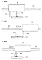
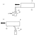
図16は、図15に示すワイパ300と印字手段3(ヘッドユニット35)との位置関係を示す図である。この図16において、印字手段3(ヘッドユニット35)とワイパ300は、図15に示すインクジェットプリンタ1の図中下側から上側を見た場合の側面図の一部として示される。ワイパ300は、図16(a)に示すように、印字手段3のノズル面、すなわち、ヘッドユニット35のノズルプレート150と当接可能なように、上下移動可能に配置される。
【0123】
ここで、ワイパ300を利用する回復処理であるワイピング処理について説明する。ワイピング処理を行う際、図16(a)に示すように、ノズル面(ノズルプレート150)よりもワイパ300の先端が上側に位置するように図示しない駆動装置によってワイパ300は上方に移動される。この場合において、キャリッジモータ41を駆動して図中左方向(矢印の方向)に印字手段3を移動させると、ワイピング部材301がノズルプレート150(ノズル面)に当接することになる。
【0124】
なお、ワイピング部材301は可撓性のゴム部材等から構成されるので、図16(b)に示すように、ワイピング部材301のノズルプレート150と当接する先端部分は撓み、その先端部によってノズルプレート150(ノズル面)の表面をクリーニング(拭き掃除)する。これにより、ノズルプレート150(ノズル面)に付着した紙粉などの異物(例えば、紙粉、空気中に浮遊するごみ、ゴムの切れ端など)を除去することができる。また、このような異物の付着状態に応じて(異物が多く付着している場合には)、印字手段3(ヘッドユニット35)にワイパ300の上方を往復移動させることによって、ワイピング処理を複数回実施することもできる。
【0125】
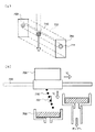
図17は、ポンプ吸引処理時における、ヘッドユニット35と、キャップ310およびポンプ320との関係を示す図である。チューブ321は、ポンピング処理(ポンプ吸引処理)におけるインク排出路を形成するものであり、その一端は、上述のように、キャップ310の底部に接続され、他端は、チューブポンプ320を介して排インクカートリッジ340に接続されている。
【0126】
キャップ310の内部底面には、インク吸収体330が配置されている。このインク吸収体330は、ポンプ吸引処理やフラッシング処理においてインクジェットヘッド100のノズル110から吐出されるインクを吸収して、一時貯蔵する。なお、インク吸収体330によって、キャップ310内へのフラッシング動作時に、吐出された液滴が跳ね返ってノズルプレート150を汚すことを防止することができる。
【0127】
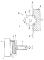
図18は、図17に示すチューブポンプ320の構成を示す概略図である。この図18(B)に示すように、チューブポンプ320は、回転式ポンプであり、回転体322と、その回転体322の円周部に配置された4つのローラ323と、ガイド部材350とを備えている。なお、ローラ323は、回転体322により支持されており、ガイド部材350のガイド351に沿って円弧状に載置された可撓性のチューブ321を加圧するものである。
【0128】
このチューブポンプ320は、軸322aを中心にして回転体322を図18(B)に示す矢印X方向に回転させることにより、チューブ321に当接している一つまたは2つのローラ323が、Y方向に回転しながら、ガイド部材350の円弧状のガイド351に載置されたチューブ321を順次加圧する。これにより、チューブ321が変形し、このチューブ321内に発生した負圧により、各インクジェットヘッド100のキャビティ141内のインク(液状材料)がキャップ310を介して吸引され、気泡が混入し、あるいは乾燥により増粘した不要なインクがノズル110を介して、インク吸収体330に排出され、このインク吸収体330に吸収された排インクがチューブポンプ320を介して排インクカートリッジ340(図17参照)に排出される。
【0129】
なお、このチューブポンプ320は、図示しないパルスモータなどのモータにより駆動される。パルスモータは、制御部6により制御される。チューブポンプ320の回転制御に対する駆動情報、例えば、回転速度、回転数が記述されたルックアップテーブル、シーケンス制御が記述された制御プログラムなどは、制御部6のPROM64などに格納されており、これらの駆動情報に基づいて、制御部6のCPU61によってチューブポンプ320の制御が行われている。
【0130】
さて、このような回復手段24を備えるインクジェットプリンタ1では、液滴不吐出検出装置50や60によりヘッドユニット35の各インクジェットヘッド100に対して吐出異常の有無の検出を行った結果、吐出異常が検出された場合には、回復手段24によって、上述したフラッシング処理、ポンピング処理、ワイピング処理のうちの少なくとも1つの回復処理を行うように作動する。これにより、吐出異常が生じたインクジェットヘッド100を正常な状態に回復させることができ、その後の印刷動作において吐出異常(ドット抜け)が発生するのを防止することができる。
【0131】
また、このようにして回復手段24による回復処理を行った場合には、その後、液滴不吐出検出装置50や60による検出を再度行うことが好ましい。これにより、回復処理によって、インクジェットヘッド100の異常が解消されたかどうか(正常状態に回復したかどうか)を確認することができ、その後の印刷動作において吐出異常(ドット抜け)が発生するのをより確実に防止することができる。なお、この再度の検出によっても吐出異常が検出された場合には、回復手段24によるフラッシング処理、ポンピング処理、ワイピング処理のうちの少なくとも1つの回復処理を行うのが好ましい。
【0132】
次に、本発明における液滴吐出ヘッド(インクジェットヘッド)の他の構成例について説明する。本発明における液滴吐出ヘッドは、前述したインクジェットヘッド100のような構成のものに限らず、いかなるものでもよく、例えば、以下に説明するインクジェットヘッド100A〜100Eのような構成のものであってもよい。
【0133】
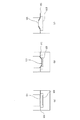
図19〜図22は、それぞれ、インクジェットヘッド(ヘッドユニット)の他の構成例を示す断面図である。図23および図24は、インクジェットヘッド(ヘッドユニット)のさらに他の構成例を示す斜視図および断面図である。以下、これらの図に基づいて説明するが、前述した実施形態と相違する点を中心に説明し、同様の事項についてはその説明を省略する。
【0134】
図19に示すインクジェットヘッド100Aは、圧電素子200の駆動により振動板212が振動し、キャビティ208内のインク(液体)がノズル203から吐出するものである。ノズル(孔)203が形成されたステンレス鋼製のノズルプレート202には、ステンレス鋼製の金属プレート204が接着フィルム205を介して接合されており、さらにその上に同様のステンレス鋼製の金属プレート204が接着フィルム205を介して接合されている。そして、その上には、連通口形成プレート206およびキャビティプレート207が順次接合されている。
ノズルプレート202、金属プレート204、接着フィルム205、連通口形成プレート206およびキャビティプレート207は、それぞれ所定の形状(凹部が形成されるような形状)に成形され、これらを重ねることにより、キャビティ208およびリザーバ209が形成される。キャビティ208とリザーバ209とは、インク供給口210を介して連通している。また、リザーバ209は、インク取入れ口211に連通している。
【0135】
キャビティプレート207の上面開口部には、振動板212が設置され、この振動板212には、下部電極213を介して圧電素子(ピエゾ素子)200が接合されている。また、圧電素子200の下部電極213と反対側には、上部電極214が接合されている。ヘッドドライバ215は、駆動電圧波形を生成する駆動回路を備え、上部電極214と下部電極213との間に駆動電圧波形を印加(供給)することにより、圧電素子200が振動し、それに接合された振動板212が振動する。この振動板212の振動によりキャビティ208の容積(キャビティ内の圧力)が変化し、キャビティ208内に充填されたインク(液体)がノズル203より液滴として吐出する。
液滴の吐出によりキャビティ208内で減少した液量は、リザーバ209からインクが供給されて補給される。また、リザーバ209へは、インク取入れ口211からインクが供給される。
【0136】
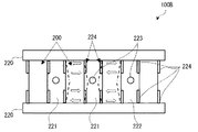
図20に示すインクジェットヘッド100Bも前記と同様に、圧電素子200の駆動によりキャビティ221内のインク(液体)がノズルから吐出するものである。このインクジェットヘッド100Bは、一対の対向する基板220を有し、両基板220間に、複数の圧電素子200が所定間隔をおいて間欠的に設置されている。
【0137】
隣接する圧電素子200同士の間には、キャビティ221が形成されている。キャビティ221の図20中前方にはプレート(図示せず)、後方にはノズルプレート222が設置され、ノズルプレート222の各キャビティ221に対応する位置には、ノズル(孔)223が形成されている。
各圧電素子200の一方の面および他方の面には、それぞれ、一対の電極224が設置されている。すなわち、一つの圧電素子200に対し、4つの電極224が接合されている。これらの電極224のうち所定の電極間に所定の駆動電圧波形を印加することにより、圧電素子200がシェアモード変形して振動し(図20において矢印で示す)、この振動によりキャビティ221の容積(キャビティ内の圧力)が変化し、キャビティ221内に充填されたインク(液体)がノズル223より液滴として吐出する。すなわち、インクジェットヘッド100Bでは、圧電素子200自体が振動板として機能する。
【0138】
図21に示すインクジェットヘッド100Cも前記と同様に、圧電素子200の駆動によりキャビティ233内のインク(液体)がノズル231から吐出するものである。このインクジェットヘッド100Cは、ノズル231が形成されたノズルプレート230と、スペーサ232と、圧電素子200とを備えている。圧電素子200は、ノズルプレート230に対しスペーサ232を介して所定距離離間して設置されており、ノズルプレート230と圧電素子200とスペーサ232とで囲まれる空間にキャビティ233が形成されている。
【0139】
圧電素子200の図21中上面には、複数の電極が接合されている。すなわち、圧電素子200のほぼ中央部には、第1電極234が接合され、その両側部には、それぞれ第2の電極235が接合されている。第1電極234と第2電極235との間に所定の駆動電圧波形を印加することにより、圧電素子200がシェアモード変形して振動し(図21において矢印で示す)、この振動によりキャビティ233の容積(キャビティ内の圧力)が変化し、キャビティ233内に充填されたインク(液体)がノズル231より液滴として吐出する。すなわち、インクジェットヘッド100Cでは、圧電素子200自体が振動板として機能する。
【0140】
図22に示すインクジェットヘッド100Dも前記と同様に、圧電素子200の駆動によりキャビティ245内のインク(液体)がノズル241から吐出するものである。このインクジェットヘッド100Dは、ノズル241が形成されたノズルプレート240と、キャビティプレート242と、振動板243と、複数の圧電素子200を積層してなる積層圧電素子201とを備えている。
【0141】
キャビティプレート242は、所定の形状(凹部が形成されるような形状)に成形され、これにより、キャビティ245およびリザーバ246が形成される。キャビティ245とリザーバ246とは、インク供給口247を介して連通している。また、リザーバ246は、インク供給チューブ311を介してインクカートリッジ31と連通している。
【0142】
積層圧電素子201の図22中下端は、中間層244を介して振動板243と接合されている。積層圧電素子201には、複数の外部電極248および内部電極249が接合されている。すなわち、積層圧電素子201の外表面には、外部電極248が接合され、積層圧電素子201を構成する各圧電素子200同士の間(または各圧電素子の内部)には、内部電極249が設置されている。この場合、外部電極248と内部電極249の一部が、交互に、圧電素子200の厚さ方向に重なるように配置される。
【0143】
そして、外部電極248と内部電極249との間にヘッドドライバ33より駆動電圧波形を印加することにより、積層圧電素子201が図22中の矢印で示すように変形して(図22上下方向に伸縮して)振動し、この振動により振動板243が振動する。この振動板243の振動によりキャビティ245の容積(キャビティ内の圧力)が変化し、キャビティ245内に充填されたインク(液体)がノズル241より液滴として吐出する。
液滴の吐出によりキャビティ245内で減少した液量は、リザーバ246からインクが供給されて補給される。また、リザーバ246へは、インクカートリッジ31からインク供給チューブ311を介してインクが供給される。
【0144】
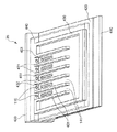
図23および図24に示すヘッドユニット35(インクジェットヘッド100E)は、いわゆる膜沸騰インクジェット方式(サーマルジェット方式)によるもので、支持板410と、基板420と、外壁430および隔壁431と、天板440とが、図23および図24中下側からこの順に接合された構成のものである。
【0145】
基板420と天板440とは、外壁430および等間隔で平行に配置された複数(図示の例では6枚)の隔壁431を介して所定の間隔をおいて設置されている。そして、基板420と天板440との間には、隔壁431によって区画された複数(図示の例では5個)のキャビティ(圧力室:インク室)141が形成されている。各キャビティ141は、短冊状(直方体状)をなしている。
【0146】
また、図23および図24に示すように、各キャビティ141の図24中左側端部(図23中上端)は、ノズルプレート(前板)433により覆われている。このノズルプレート433には、各キャビティ141に連通するノズル(孔)110が形成されており、このノズル110からインク(液状材料)が吐出する。
図23では、ノズルプレート433に対しノズル110が直線的に、すなわち列状に配置されているが、ノズルの配置パターンはこれに限定されないことは言うまでもない。
【0147】
なお、ノズルプレート433を設けず、各キャビティ141の図23中上端(図24中左端)が開放しており、この開放した開口がノズルとなるような構成のものでもよい。
また、天板440には、インク取り入れ口441が形成され、該インク取り入れ口441には、インク供給チューブ311を介して、インクカートリッジ31に接続されている。
【0148】
基板420の各キャビティ141に対応する箇所には、それぞれ、発熱体450が設置(埋設)されている。各発熱体450は、ヘッドドライバ(通電手段)33により、それぞれ別個に通電され、発熱する。ヘッドドライバ33は、制御部6から入力される印刷信号(印刷データ)に応じ、発熱体450の駆動信号として例えばパルス状の信号を出力する。
【0149】
また、発熱体450のキャビティ141側の面は、保護膜(耐キャビテーション膜)451で覆われている。この保護膜451は、発熱体450がキャビティ141内のインクと直接接触するのを防止するために設けられたものである。この保護膜451を設けることにより、発熱体450がインクと接触することによる変質、劣化等を防止することができる。
【0150】
次に、インクジェットヘッド100Eの作用(作動原理)について説明する。
ヘッドドライバ33から駆動信号(パルス信号)が出力されて発熱体450に通電されると、発熱体450は、瞬時に300℃以上の温度に発熱する。これにより、保護膜451上に膜沸騰による気泡(前述した吐出異常の原因となるキャビティ内に混入、発生する気泡とは異なる)480が発生し、該気泡480は瞬時に膨張する。これにより、キャビティ141内に満たされたインク(液状材料)の液圧が増大し、インクの一部がノズル110から液滴として吐出される。
インク滴の吐出によりキャビティ141内で減少した液量は、インク取り入れ口441から新たなインクがキャビティ141内に供給されて補給される。このインクは、インクカートリッジ31からインク供給チューブ311内を通って供給される。
【0151】
以上、本発明の液滴不吐出検出装置および液滴吐出装置を図示の各実施形態に基づいて説明したが、本発明は、これに限定されるものではなく、液滴不吐出検出装置あるいは液滴吐出装置を構成する各部は、同様の機能を発揮し得る任意の構成のものと置換することができ、また、他の任意の構成物が付加されていてもよい。
【0152】
なお、本発明では、液滴吐出ヘッド(上述の実施形態では、インクジェットヘッド100)から吐出する吐出対象液(液滴)としては、特に限定されず、例えば以下のような各種の材料を含む液体(サスペンション、エマルション等の分散液を含む)とすることができる。すなわち、カラーフィルタのフィルタ材料(インク)、有機EL(Electro Luminescence)装置におけるEL発光層を形成するための発光材料、電子放出装置における電極上に蛍光体を形成するための蛍光材料、PDP(Plasma Display Panel)装置における蛍光体を形成するための蛍光材料、電気泳動表示装置における泳動体を形成する泳動体材料、基板Wの表面にバンクを形成するためのバンク材料、各種コーティング材料、電極を形成するための液状電極材料、2枚の基板間に微小なセルギャップを構成するためのスペーサを構成する粒子材料、金属配線を形成するための液状金属材料、マイクロレンズを形成するためのレンズ材料、レジスト材料、光拡散体を形成するための光拡散材料、DNAチップやプロテインチップなどのバイオセンサに利用する各種試験液体材料などである。
また、本発明では、液滴を吐出する対象となる液滴受容物は、記録用紙のような紙に限らず、フィルム、織布、不織布等の他のメディアや、ガラス基板、シリコン基板等の各種基板のようなワークであってもよい。
【図面の簡単な説明】
【図1】本発明の液滴吐出装置の一種であるインクジェットプリンタの構成を示す概略図である。
【図2】本発明のインクジェットプリンタ(液滴吐出装置)の主要部を概略的に示すブロック図である。
【図3】図1に示すインクジェットプリンタにおけるヘッドユニット(インクジェットヘッド)の概略的な断面図である。
【図4】図3のヘッドユニットの構成を示す分解斜視図である。
【図5】4色インクを用いるヘッドユニットのノズルプレートのノズル配置パターンの一例である。
【図6】図3のIII−III断面の駆動信号入力時の各状態を示す状態図である。
【図7】図1に示すインクジェットプリンタが備える液滴不吐出検出装置のセンサの構成を示す図およびセンサの周辺を示す側面図である。
【図8】図7に示すセンサを覆うカバーを示す断面図である。
【図9】図1に示すインクジェットプリンタ1が備える液滴不吐出検出装置の構成を示すブロック図である。
【図10】センサに付着したインク滴の数(累積インク滴数)と、1次振動の周波数との関係を示すグラフである。
【図11】センサに付着したインク滴の数(累積インク滴数)と、3次振動の周波数との関係を示すグラフである。
【図12】清掃手段の構成を示す側面図である。
【図13】本発明の液滴不吐出検出装置の他の実施形態におけるセンサを示す図である。
【図14】本発明の液滴不吐出検出装置の他の実施形態の主腰部を模式的に示す図(一部ブロック図)である。
【図15】図1に示すインクジェットプリンタの上部から見た概略的な構造(一部省略)を示す図である。
【図16】図15に示すワイパとヘッドユニットとの位置関係を示す図である。
【図17】ポンプ吸引処理時における、ヘッドユニットと、キャップおよびポンプとの関係を示す図である。
【図18】図17に示すチューブポンプの構成を示す概略図である。
【図19】本発明におけるインクジェットヘッドの他の構成例の概略を示す断面図である。
【図20】本発明におけるインクジェットヘッドの他の構成例の概略を示す断面図である。
【図21】本発明におけるインクジェットヘッドの他の構成例の概略を示す断面図である。
【図22】本発明におけるインクジェットヘッドの他の構成例の概略を示す断面図である。
【図23】本発明におけるインクジェットヘッドのさらに他の構成例を示す斜視図である。
【図24】図23に示すインクジェットヘッドの断面図である。
【図25】従来の光学式のインク滴検出方法の原理を示す模式図である。
【符号の説明】
1……インクジェットプリンタ 2……装置本体 21……トレイ 22……排紙口 3……印字手段 31……インクカートリッジ 311……インク供給チューブ 32……キャリッジ 33……ヘッドドライバ 34……連結部 35……ヘッドユニット 4……印刷装置 41……キャリッジモータ 42……往復動機構 421……タイミングベルト 422……キャリッジガイド軸 43……キャリッジモータドライバ 44……プーリ 5……給紙装置 51……給紙モータ 52……給紙ローラ 52a……従動ローラ 52b……駆動ローラ 53……給紙モータドライバ 6……制御部 61……CPU 62……EEPROM 63……RAM 64……PROM 7……操作パネル 8……ホストコンピュータ 9……IF 24……回復手段 100、100A〜100E……インクジェットヘッド 110‥‥ノズル 120……静電アクチュエータ 121……振動板(底壁) 122……セグメント電極 123……絶縁層124……共通電極 124a……入力端子 130……ダンパ室 131……インク取入れ口 132……ダンパ 140……シリコン基板 141……キャビティ 142……インク供給口 143……リザーバ 150……ノズルプレート 160……ガラス基板 161……凹部 162……対向壁 200……圧電素子 201……積層圧電素子 202、222、230、240……ノズルプレート 203、223、231、241……ノズル 204……金属プレート 205……接着フィルム 206……連通口形成プレート 207、242……キャビティプレート 208、221、233、245……キャビティ209、246……リザーバ 210、247……インク供給口 211……インク取入れ口 212、243……振動板 213……下部電極 214……上部電極 215……ヘッドドライバ 220……基板 224……電極 232……スペーサ 234……第1電極 235……第2電極 244……中間層248……外部電極 249……内部電極 300……ワイパ 301……ワイピング部材 310……キャップ 320……チューブポンプ(回転式ポンプ) 321……(可撓性)チューブ 322……回転体 322a……軸 323……ローラ 330……インク吸収体 340……排インクカートリッジ 350……ガイド部材 351……ガイド P……記録用紙 50、60……液滴不吐出検出装置 500、600……センサ 501、601……圧電部材 502、503……電極 504、505、606、607……保護膜 510……インク滴 510’……残留したインク滴 512……カバー 520……発振回路 521、523……抵抗 522、526……インバータ 524、525……コンデンサ 530……カウンタ計測回路 540……演算処理判定回路 550……清掃手段 602、603……櫛歯状電極 604……入力信号線 605……出力信号線 608……表面弾性波 609……検出領域 610……高周波発信器 620……ベクトル電圧計[0001]
TECHNICAL FIELD OF THE INVENTION
The present invention relates to a droplet non-discharge detection device and a droplet discharge device.
[0002]
[Prior art]
Conventionally, when the nozzle hole of the ink jet head such as an ink jet printer is clogged, paper dust or foreign matter adheres, or when bubbles enter the cavity of the ink jet head, the ink droplets are not ejected when it should be ejected was there.
[0003]
In order to detect whether or not an ink droplet has been ejected, there is a method of using various sensors mainly for detecting the ink droplet. Among them, the method of detecting that an ink droplet has been ejected from a nozzle using an optical sensor can be reliably detected by appropriately selecting an ink droplet diameter and a light beam diameter and performing accurate positioning. Many suggestions have been made.
[0004]
This method is excellent in that it can be applied even if the ink droplet ejection principle (piezo method, thermal jet method, solid ink method, etc.) of the ink jet printer is different. Further, even when the ink droplet does not fly straight, but bends and flies, and the landing position on the recording paper shifts, the ink droplet does not pass through the detection area, and thus can be detected.
[0005]
FIG. 25A is a schematic diagram showing the principle of a conventional optical ink droplet detection method.
Light from the light-emitting element exits the light-emitting
[0006]
Then, since the amount of light entering the light receiving element decreases, the voltage when converted into an electric signal decreases, and the
[0007]
FIG. 25B is a diagram illustrating a state in which the
When the
[0008]
Conversely, if the timing of the detection of the
Specifically, for example, the detection optical axis determined by the light emitting element and the light receiving element of the photo sensor for detecting the ink ejection is set at a predetermined angle relative to the arrangement direction of the ink ejection ports of the inkjet head. There is a technology of disposing the photosensors to widen a detection range by a photosensor (Patent Document 1).
[0009]
However, in the technique described in Patent Document 1, the detection timing becomes gentler by the amount that the ink droplets penetrate the light receiving region obliquely without lowering the sensitivity, but the improvement effect is still relatively small. Unless the positional relationship between the ink ejection port and the detection area is set with high precision so that the ink droplet passes on the diagonal line of the detection area, the detection range may be narrowed.
Further, as another detection method, a reflection plate having high water repellency to ink and a sensor for detecting the amount of reflected light are provided. (Patent Document 2).
[0010]
However, the technique described in
Further, it has been proposed to use a piezoelectric vibrator as a sensor for monitoring the amount of ink held in an ink tank (Patent Document 3).
[0011]
However, in the technique described in
[0012]
[Patent Document 1]
JP-A-9-94948
[Patent Document 2]
JP-A-8-332736
[Patent Document 3]
JP-A-7-137276
[0013]
[Problems to be solved by the invention]
An object of the present invention is to eliminate the need for setting the positional relationship between a discharge nozzle of a droplet discharge head and a droplet detection unit with high accuracy, and to ensure high reliability even during long-term use to determine whether there is a discharge abnormality. An object of the present invention is to provide a droplet non-discharge detection device and a droplet discharge device capable of detecting the presence or absence of a discharge abnormality even if the amount of discharged droplets is small.
[0014]
[Means for Solving the Problems]
Such an object is achieved by the present invention described below.
The droplet non-discharge detection device of the present invention is a droplet non-discharge detection device that detects a discharge abnormality of a droplet discharge head that discharges a droplet,
A sensor having a piezoelectric member provided with electrodes and oscillating at a predetermined natural frequency,
Driving means for oscillating the sensor at a predetermined natural frequency,
In a state where the sensor is oscillating at a predetermined natural frequency, when the droplet discharge head performs a discharge operation of discharging droplets toward the sensor, the natural frequency of the sensor or the natural frequency Detecting means for detecting a physical quantity corresponding to the number and detecting the presence or absence of a discharge abnormality of the droplet discharge head based on the detected value.
[0015]
Thus, substantially the entire sensor can be used as a detection region of a droplet including an ink droplet, and by setting the area (detection region) of the sensor to a predetermined size, the area of the sensor can be changed to the discharge nozzle of the droplet discharge head. There is no need to set the positional relationship with the sensor with high precision, which makes assembly and manufacturing easy, and ensures that there is high reliability even during long-term use to detect the presence or absence of abnormal discharge. In addition, it is possible to provide a droplet non-discharge detection device capable of detecting even a small amount of discharged droplets, that is, detecting the presence or absence of a discharge abnormality.
[0016]
In the droplet non-discharge detection device of the present invention, the piezoelectric member has a plate shape, and electrodes are provided on both surfaces of the piezoelectric member.
It is preferable that the detection means detects the presence or absence of the discharge abnormality based on a change in the detection value.
In the droplet non-ejection detection device of the present invention, the driving unit oscillates the sensor at a predetermined natural frequency, and has an oscillation circuit including the sensor.
It is preferable that the detecting means includes a measuring means for counting the number of pulses of the output signal from the oscillation circuit within a predetermined time.
In the droplet ejection failure detection apparatus according to the present invention, it is preferable that the vibration mode of the sensor is a thickness shear vibration.
[0017]
The droplet non-discharge detection device of the present invention is a droplet non-discharge detection device that detects a discharge abnormality of a droplet discharge head that discharges a droplet,
A sensor that has a piezoelectric member provided with electrodes and propagates a surface acoustic wave;
Driving means for driving the sensor and causing the sensor to propagate surface acoustic waves;
When the droplet ejection head performs an ejection operation for ejecting droplets toward the sensor while the sensor is propagating the surface acoustic wave, the amplitude of the propagated surface acoustic wave or the amplitude of the transmitted Detecting means for detecting a corresponding physical quantity and detecting the presence or absence of a discharge abnormality of the droplet discharge head based on the detected value.
[0018]
As a result, there is no need to set the positional relationship between the ejection nozzles of the droplet ejection head and the sensor with high precision, which facilitates assembly and manufacture, and ensures high reliability even during long-term use. In addition, it is possible to detect the presence / absence of a discharge abnormality, and to detect even a smaller amount of the discharged droplet, that is, to detect the presence / absence of a discharge abnormality. A detection device can be provided.
[0019]
In the droplet ejection failure detection device of the present invention, the piezoelectric member has a plate shape, and a pair of comb-shaped first electrodes is provided on one end of one surface of the piezoelectric member. A pair of comb-shaped second electrodes is provided on the side, and a surface acoustic wave is configured to propagate from the first electrode side of the sensor to the second electrode side;
When the droplet discharging head performs a discharging operation of discharging droplets between the first electrode and the second electrode of the sensor, the detecting unit may detect the second electrode. It is preferable that the amplitude of the propagated surface acoustic wave or a physical quantity corresponding to the amplitude is detected, and the presence or absence of the discharge abnormality is detected based on a change in the detected value.
[0020]
In the droplet ejection failure detection device of the present invention, the driving unit has a high-frequency oscillation circuit connected to the first electrode side,
Preferably, the detection means has a vector voltmeter connected to the second electrode.
In the droplet ejection failure detection device according to the aspect of the invention, it is preferable that the sensor has a protective film that covers the electrode.
Thereby, the electrodes of the sensor can be shielded from the outside air and the like, so that corrosion of the electrodes can be prevented.
[0021]
It is preferable that the droplet non-discharge detection device of the present invention further includes a cleaning unit that removes droplets remaining on the sensor.
This makes it possible to remove the liquid droplets remaining on the sensor, so that the presence or absence of a discharge abnormality can be more reliably detected.
It is preferable that the droplet non-discharge detection device of the present invention further includes a cover that is relatively movably provided between a position covering the sensor and a position not covering the sensor.
Accordingly, it is possible to prevent dust and the like from adhering to the sensor, and thus it is possible to more reliably prevent erroneous detection due to the adhesion of dust and the like.
[0022]
The droplet discharge device according to the present invention is a droplet discharge head that discharges the liquid as droplets from a nozzle communicating with the cavity by driving an actuator by a drive circuit to change the pressure in the cavity filled with the liquid. When,
The liquid ejection failure detecting device according to the present invention is provided.
As a result, there is no need to set the positional relationship between the ejection nozzles of the droplet ejection head and the sensor with high precision, which facilitates assembly and manufacture, and ensures high reliability even during long-term use. Droplet non-discharge detection device capable of detecting the presence or absence of a discharge abnormality, and detecting the amount of discharged droplets even if the amount is small, that is, detecting the presence or absence of a discharge abnormality Can be provided.
[0023]
In the droplet discharge device of the present invention, the droplet discharge head further includes a recovery unit that performs recovery processing for eliminating a cause of the discharge abnormality,
When an abnormal discharge is detected by the droplet non-discharge detection device, it is preferable to perform a recovery process by the recovery unit.
This makes it possible to recover the droplet discharge head in which the discharge abnormality has occurred to a normal state, thereby preventing occurrence of a discharge abnormality (missing dot) in a subsequent printing operation.
[0024]
In the droplet discharge device of the present invention, it is preferable that after the recovery processing by the recovery unit is performed, the detection by the droplet non-discharge detection device is performed again.
As a result, it is possible to confirm whether or not the abnormality of the droplet discharge head has been eliminated (whether or not the liquid droplet has been recovered to a normal state) by the recovery process, and it is possible to prevent the occurrence of the discharge abnormality (missing dots) in the subsequent printing operation. This can be more reliably prevented.
[0025]
In the droplet discharge device according to the aspect of the invention, it is preferable that the recovery unit includes a wiping unit that performs a wiping process of wiping a nozzle surface on which nozzles of the droplet discharge head are arranged with a wiper.
Accordingly, it is possible to perform a recovery process suitable for recovering from a discharge abnormality when a foreign substance such as paper dust adheres to the outlet of the discharge nozzle of the droplet discharge head.
[0026]
In the droplet discharge device according to the aspect of the invention, it is preferable that the recovery unit includes a pumping unit that performs a pump suction process using a pump connected to a cap that covers a nozzle surface of the droplet discharge head.
Accordingly, it is possible to perform a recovery process suitable for recovering from a discharge abnormality when the discharge nozzle of the droplet discharge head is clogged or when air bubbles are mixed in the cavity.
[0027]
It is preferable that the droplet discharge device of the present invention further includes a moving unit that moves the sensor.
This makes it possible to detect a discharge abnormality of the droplet discharge head at any position.
In the droplet discharge device of the present invention, it is preferable that the droplet discharge device is an ink jet printer.
[0028]
BEST MODE FOR CARRYING OUT THE INVENTION
Hereinafter, a preferred embodiment of the droplet discharge device of the present invention will be described in detail with reference to FIGS. This embodiment is given as an example, and the content of the present invention should not be interpreted in a limited manner. Hereinafter, in the present embodiment, an ink jet printer that discharges ink (liquid material) and prints an image on a recording sheet (droplet receptor) will be described as an example of the droplet discharge device of the present invention.
[0029]
FIG. 1 is a schematic diagram showing a configuration of an ink jet printer 1 which is a kind of a droplet discharge device according to an embodiment of the present invention. In the following description, the upper side in FIG. 1 is referred to as “upper”, and the lower side is referred to as “lower”. First, the configuration of the inkjet printer 1 will be described.
The ink jet printer 1 shown in FIG. 1 includes an apparatus
[0030]
The
Further, inside the apparatus
[0031]
Under the control of the
[0032]
The
[0033]
Note that full-color printing can be performed by using an
[0034]
The
The
[0035]
When the
[0036]
The
The
[0037]
Further, the
The
[0038]
FIG. 2 is a block diagram schematically showing a main part of the ink jet printer of the present invention. 2, the inkjet printer 1 of the present invention drives an interface unit (IF: Interface) 9 for receiving print data and the like input from a
[0039]
2, the
[0040]
As described above, the
[0041]
Although not shown, various sensors capable of detecting a printing environment such as a remaining amount of ink in the
When obtaining the print data from the
[0042]
Next, the structure of each
[0043]
As shown in FIG. 3, the
[0044]
In the
[0045]
Each of these
[0046]
Each of the
[0047]
On the surface of the glass substrate 160 on the
[0048]
Here, the bottom wall (diaphragm) 121 of each
(Composition). Therefore, a main part of the
[0049]
As shown in FIG. 3, a
[0050]
As shown in FIG. 4, the
[0051]
In FIG. 4, the
[0052]
FIG. 6 shows each state at the time of inputting the drive signal in the section taken along the line III-III of FIG. When a driving voltage is applied between the opposing electrodes from the
[0053]
Now, in each of the inkjet heads 100 of the
[0054]
When this ejection abnormality occurs, as a result, typically, a droplet is not ejected from the
[0055]
Then, such an ink jet printer 1 detects whether or not there is a discharge abnormality of the head unit 35 (each ink jet head 100), that is, whether or not the
[0056]
Next, the droplet
FIG. 7A is a plan view, a rear view, and a cross-sectional side view showing a configuration of a
[0057]
Note that in the plan view and the rear view of FIG. 7A and the plan view and the rear view of FIG. 7B, the protective film is not shown, and the electrodes and wires are hatched.
The droplet non-ejection detecting
As shown in FIG. 7A, a
[0058]
Needless to say, the
[0059]
In this embodiment, the shape of the sensor 500 (piezoelectric member 501) in plan view is substantially rectangular as shown in FIG. 7A. In the droplet
The size of the detection region is not particularly limited, but may be, for example, slightly larger than the area of the region in the
[0060]
The
In the present invention, the shape of the sensor 500 (piezoelectric member 501) is not particularly limited. For example, the shape in a plan view may be substantially circular as shown in FIG. , And other shapes.
[0061]
Further, the piezoelectric material to be used is not particularly limited. 2 ), Lithium tantalate (LiTaO) 3 ), Langasite (La 3 Ga 5 SiO 14 ), Potassium niobate (KNbO) 3 ), Lithium niobate (LiNbO) 3 ), Zinc oxide (ZnO), polyvinylidene fluoride (PVDF), ferroelectric barium titanate (BaTiO) having a perovskite crystal structure 3 ), Lead titanate (PbTiO) 3 ), Various kinds of materials such as lead lanthanum zirconate titanate (PLZT) obtained by adding a small amount of La to lead zirconate titanate (PZT) can be used.
[0062]
The constituent materials of the
Here, in a vibrator using the
The vibration mode of the
[0063]
As shown in FIG. 9A, the droplet non-ejection detecting
[0064]
Next, the principle (method) of detecting a discharge abnormality of the inkjet head (droplet discharge head) 100 by the droplet
First, when the Colpitts oscillation circuit shown in FIG. 9B is formed using the
[0065]
Next, the head unit 35 (each inkjet head 100) performs an ejection operation to eject the
In this state, when the
[0066]
The droplet non-ejection detecting
That is, when the
[0067]
The physical quantity corresponding to the natural frequency includes, for example, the number of vibrations (number of times) of the
Here, in the vibration mode in which the
f0 = N / t
It is expressed as
[0068]
The frequency (frequency) that changes when the
Δt = (ρ2 · v2) / (ρ1 · S2)
It is expressed as
Due to this thickness change Δt, the oscillation frequency (natural frequency) f of the
f = N / (t + Δt)
It becomes.
[0069]
FIG. 9B is a circuit diagram illustrating a configuration example of the
The
[0070]
As described above, when the
Therefore, based on the output signal of the
Although a Colpitts-type oscillation circuit is shown here as an example of the
[0071]
FIG. 10 is a graph showing the relationship between the number of ink droplets 510 (the cumulative number of ink droplets) attached to the
More specifically, the head unit for the circular quartz oscillator shown in FIG. 7B, having an outer diameter of 12.4 mm, a vibration mode of thickness shear oscillation, and a primary oscillation of about 5 MHz. A total of 1000 shots of 100 ink drops 510 were dropped from 35 ink jet heads 100, and the oscillation frequency of the quartz oscillator was measured sequentially.
The measurement results are as shown in the graph of FIG.
[0072]
FIG. 11 is a graph showing the relationship between the number of ink droplets 510 (accumulated number of ink droplets) attached to the
More specifically, a head unit is provided for the crystal unit having a circular shape shown in FIG. 7B and having an outer diameter of 12.4 mm, a vibration mode of thickness shear vibration, and a tertiary vibration of approximately 15 MHz. A total of 1000 shots of 100 ink drops 510 were dropped from 35 ink jet heads 100, and the oscillation frequency of the quartz oscillator was measured sequentially.
The measurement results are as shown in the graph of FIG.
[0073]
As can be seen from the above measurement results, as the number (volume) of the
[0074]
Here, the natural frequency of the
Accordingly, high sensitivity is obtained, the
The droplet
FIG. 12 is a side view showing the configuration of the cleaning means 550.
[0075]
As shown in the figure, the
The
[0076]
When the
[0077]
The timing and the number of times of cleaning the
In the droplet
[0078]
The
Further, the inkjet printer 1 of the present embodiment has a moving unit (not shown) for moving the
[0079]
As shown in FIG. 8, the droplet
The
[0080]
Next, the operation of the droplet
When detecting the presence / absence of a discharge abnormality of the head unit 35 (each ink jet head 100), the
[0081]
Next, the
Next, the
[0082]
Next, the
Here, the “pulse” includes not only a rectangular wave whose waveform is shaped, but also a signal (output signal) itself output from the
[0083]
In the processing described later, the count value may be used as it is, or the oscillation frequency of the
The measurement gate time is not particularly limited. For example, by adjusting the measurement gate time, the count value of the
[0084]
The measurement result of the
In this state, when the
[0085]
Next, the
The measurement result of the
[0086]
When the
[0087]
The arithmetic
[0088]
On the other hand, when the
In this case, as described above, the natural frequency of the
[0089]
For example, the arithmetic
In this manner, the droplet
[0090]
As described above, according to the droplet
[0091]
In addition, the detection area can be easily enlarged, and the area of the detection area is set to be slightly larger than the area of the area where the
Further, the configuration of the
[0092]
FIG. 13A is a plan view and a cross-sectional side view showing a sensor in another embodiment of the droplet non-discharge detection device of the present invention, and FIG. 13B is a sensor corresponding to the
[0093]
Note that, in the plan view of FIG. 13A, the protective film is not shown (only the boundary between the protective film and the piezoelectric member is shown), and the comb-shaped electrodes are hatched.
Hereinafter, other embodiments of the droplet non-discharge detection device according to the present invention will be described with reference to these drawings. The description will focus on differences from the droplet
[0094]
The droplet
As shown in FIG. 13A, a
[0095]
The pair of comb-shaped
The vibration mode of the
[0096]
Further, in the present embodiment, the shape of the sensor 600 (piezoelectric member 601) in plan view is substantially rectangular, but is not limited thereto, and may be another shape.
[0097]
In the droplet
The set natural frequency of the
Accordingly, higher sensitivity can be obtained, the
[0098]
As shown in FIG. 14, the droplet non-ejection detecting
The pair of comb-shaped
In the present embodiment, the
[0099]
Next, the principle (method) of detecting abnormal ejection of the inkjet head (droplet ejection head) 100 by the droplet
First, an AC voltage having a predetermined frequency is applied between the pair of comb-shaped
[0100]
Next, the head unit 35 (each ink-jet head 100) detects between the pair of comb-shaped
In this state, when the
[0101]
For example, when the
[0102]
The droplet
[0103]
That is, when the
The physical quantity corresponding to the amplitude includes, for example, a value proportional to the amplitude.
[0104]
FIG. 13B is a plan view schematically showing a configuration example of the
As shown in the figure, in this
Each of the
[0105]
Next, the operation of the droplet
When detecting the presence / absence of a discharge abnormality of the head unit 35 (each ink jet head 100), the
[0106]
Next, the
Next, the
The AC voltage (high-frequency signal) output from the pair of comb-shaped
[0107]
In the lower part of FIG. 14, the waveform of the surface acoustic wave on the input side (the pair of comb-shaped electrodes 602) of the sensor 600 (the amplitude when converted to the value detected by the
[0108]
The value of the amplitude A ′ of the high-frequency signal detected by the
[0109]
The
[0110]
In this state, when the
[0111]
Next, the
The
[0112]
When the
The
[0113]
On the other hand, when the
In this case, as described above, the amplitude of the surface acoustic wave propagated to the pair of comb-shaped
[0114]
For example, the
In this manner, the droplet
[0115]
As described above, the droplet
In the present embodiment, the sensitivity is high because the natural frequency of the
Note that, in the above-described embodiment, the case where the vibration mode is the thickness shear vibration and the case where the surface acoustic wave is used have been described. However, in the present invention, the vibration mode is set to another vibration mode, for example, the trapping vibration or the like. May be set.
[0116]
Next, a configuration (recovery means 24) for executing a recovery process for eliminating the cause of the discharge abnormality (head abnormality) for the inkjet head 100 (head unit 35) in the droplet discharge apparatus of the present invention will be described. FIG. 15 is a diagram showing a schematic structure (partially omitted) as viewed from above the ink jet printer 1 shown in FIG. The ink jet printer 1 shown in FIG. 15 includes a
[0117]
The recovery process performed by the
[0118]
Here, the wiping process refers to a process of wiping foreign matter such as paper dust adhered to the nozzle plate 150 (nozzle surface) of the
[0119]
The plurality of
[0120]
The
[0121]
During the recording (printing) operation, the recording paper P moves in the sub-scanning direction, that is, downwards in FIG. 15 while driving the
[0122]
FIG. 16 is a diagram showing a positional relationship between the
[0123]
Here, the wiping process which is the recovery process using the
[0124]
Since the wiping
[0125]
FIG. 17 is a diagram illustrating the relationship between the
[0126]
An
[0127]
FIG. 18 is a schematic diagram showing the configuration of the
[0128]
The
[0129]
The
[0130]
By the way, in the ink jet printer 1 provided with such a recovery means 24, as a result of detecting whether or not there is a discharge abnormality in each of the ink jet heads 100 of the
[0131]
When the recovery process is performed by the
[0132]
Next, another configuration example of the droplet discharge head (inkjet head) according to the present invention will be described. The droplet discharge head according to the present invention is not limited to the configuration like the above-described
[0133]
19 to 22 are cross-sectional views each showing another example of the configuration of the inkjet head (head unit). FIG. 23 and FIG. 24 are a perspective view and a sectional view showing still another configuration example of the ink jet head (head unit). Hereinafter, description will be made based on these drawings, but the description will be focused on the points different from the above-described embodiment, and the description of the same matters will be omitted.
[0134]
In the
The
[0135]
A
The amount of liquid reduced in the
[0136]
In the
[0137]
A
A pair of
[0138]
In the
[0139]
A plurality of electrodes are joined to the upper surface of the
[0140]
The ink jet head 100D shown in FIG. 22 also discharges ink (liquid) in the
[0141]
The
[0142]
The lower end in FIG. 22 of the laminated
[0143]
Then, by applying a driving voltage waveform from the
The amount of liquid reduced in the
[0144]
The head unit 35 (
[0145]
The
[0146]
As shown in FIGS. 23 and 24, the left end (the upper end in FIG. 23) of each
In FIG. 23, the
[0147]
Note that the
In addition, an
[0148]
[0149]
The surface of the
[0150]
Next, the operation (operation principle) of the
When a drive signal (pulse signal) is output from the
The amount of liquid reduced in the
[0151]
As described above, the droplet non-discharge detection device and the droplet discharge device of the present invention have been described based on the illustrated embodiments. However, the present invention is not limited to this, and the droplet non-discharge detection device or the liquid Each unit constituting the droplet discharge device can be replaced with an arbitrary configuration capable of exhibiting the same function, and another arbitrary configuration may be added.
[0152]
In the present invention, the liquid to be ejected (droplets) ejected from the droplet ejection head (the
Further, in the present invention, the droplet receiver from which droplets are to be discharged is not limited to paper such as recording paper, but other media such as films, woven fabrics, and nonwoven fabrics, glass substrates, silicon substrates, and the like. Work such as various substrates may be used.
[Brief description of the drawings]
FIG. 1 is a schematic diagram showing a configuration of an ink jet printer which is a kind of a droplet discharge device of the present invention.
FIG. 2 is a block diagram schematically showing a main part of an ink jet printer (droplet discharge device) of the present invention.
FIG. 3 is a schematic sectional view of a head unit (ink jet head) in the ink jet printer shown in FIG.
FIG. 4 is an exploded perspective view showing the configuration of the head unit of FIG.
FIG. 5 is an example of a nozzle arrangement pattern of a nozzle plate of a head unit using four color inks.
6 is a state diagram showing each state at the time of inputting a drive signal in a section taken along line III-III of FIG. 3;
7 is a diagram showing a configuration of a sensor of a droplet non-discharge detection device provided in the ink jet printer shown in FIG. 1 and a side view showing a periphery of the sensor.
8 is a cross-sectional view showing a cover that covers the sensor shown in FIG.
9 is a block diagram illustrating a configuration of a droplet non-discharge detection device provided in the inkjet printer 1 illustrated in FIG.
FIG. 10 is a graph showing a relationship between the number of ink droplets (cumulative number of ink droplets) attached to a sensor and the frequency of primary vibration.
FIG. 11 is a graph showing a relationship between the number of ink droplets (cumulative number of ink droplets) attached to a sensor and the frequency of the tertiary vibration.
FIG. 12 is a side view illustrating a configuration of a cleaning unit.
FIG. 13 is a view showing a sensor in another embodiment of the droplet non-discharge detection device of the present invention.
FIG. 14 is a diagram (partially a block diagram) schematically showing a main waist portion of another embodiment of the droplet non-discharge detection device of the present invention.
15 is a diagram showing a schematic structure (partially omitted) as viewed from above the ink jet printer shown in FIG. 1;
16 is a diagram showing a positional relationship between the wiper and the head unit shown in FIG.
FIG. 17 is a diagram illustrating a relationship between a head unit, a cap, and a pump during a pump suction process.
FIG. 18 is a schematic view showing a configuration of the tube pump shown in FIG.
FIG. 19 is a cross-sectional view schematically illustrating another configuration example of the inkjet head according to the invention.
FIG. 20 is a cross-sectional view schematically illustrating another configuration example of the inkjet head according to the invention.
FIG. 21 is a cross-sectional view schematically illustrating another configuration example of the inkjet head according to the invention.
FIG. 22 is a cross-sectional view schematically illustrating another configuration example of the inkjet head according to the invention.
FIG. 23 is a perspective view showing still another configuration example of the inkjet head according to the present invention.
FIG. 24 is a sectional view of the ink jet head shown in FIG.
FIG. 25 is a schematic view showing the principle of a conventional optical ink droplet detection method.
[Explanation of symbols]
DESCRIPTION OF SYMBOLS 1 ...
Claims (16)
電極が設けられた圧電部材を有し、所定の固有振動数で発振するセンサと、
前記センサを所定の固有振動数で発振させる駆動手段と、
前記センサが所定の固有振動数で発振している状態で、前記液滴吐出ヘッドが前記センサに向けて液滴を吐出する吐出動作を行った際に、前記センサの固有振動数または当該固有振動数に対応する物理量を検出し、その検出値に基づいて前記液滴吐出ヘッドの吐出異常の有無を検出する検出手段とを備えることを特徴とする液滴不吐出検出装置。A droplet non-discharge detection device that detects a discharge abnormality of a droplet discharge head that discharges a droplet,
A sensor having a piezoelectric member provided with electrodes and oscillating at a predetermined natural frequency,
Driving means for oscillating the sensor at a predetermined natural frequency,
In a state where the sensor is oscillating at a predetermined natural frequency, when the droplet discharge head performs a discharge operation of discharging droplets toward the sensor, the natural frequency of the sensor or the natural frequency A detection unit for detecting a physical quantity corresponding to the number and detecting the presence or absence of a discharge abnormality of the droplet discharge head based on the detected value.
前記検出手段は、前記検出値の変化に基づいて前記吐出異常の有無を検出する請求項1に記載の液滴不吐出検出装置。The piezoelectric member has a plate shape, electrodes are provided on both surfaces of the piezoelectric member,
The droplet non-discharge detection device according to claim 1, wherein the detection unit detects the presence or absence of the discharge abnormality based on a change in the detection value.
前記検出手段は、前記発振回路からの出力信号の所定時間内におけるパルス数を計数する計測手段を有する請求項1または2に記載の液滴不吐出検出装置。The drive unit oscillates the sensor at a predetermined natural frequency, and has an oscillation circuit including the sensor.
3. The droplet ejection failure detection apparatus according to claim 1, wherein the detection unit includes a measurement unit that counts the number of pulses of the output signal from the oscillation circuit within a predetermined time.
電極が設けられた圧電部材を有し、表面弾性波を伝播するセンサと、
前記センサを駆動し、該センサに表面弾性波を伝播させる駆動手段と、
前記センサが表面弾性波を伝播している状態で、前記液滴吐出ヘッドが前記センサに向けて液滴を吐出する吐出動作を行った際に、前記伝播した表面弾性波の振幅または当該振幅に対応する物理量を検出し、その検出値に基づいて前記液滴吐出ヘッドの吐出異常の有無を検出する検出手段とを備えることを特徴とする液滴不吐出検出装置。A droplet non-discharge detection device that detects a discharge abnormality of a droplet discharge head that discharges a droplet,
A sensor that has a piezoelectric member provided with electrodes and propagates a surface acoustic wave;
Driving means for driving the sensor and causing the sensor to propagate surface acoustic waves;
In a state where the sensor is propagating a surface acoustic wave, when the droplet discharge head performs a discharge operation of discharging a droplet toward the sensor, the amplitude of the propagated surface acoustic wave or the amplitude of the propagated surface acoustic wave is reduced. A non-discharge detection device, comprising: a detection unit that detects a corresponding physical quantity and detects whether or not there is a discharge abnormality of the droplet discharge head based on the detected value.
前記液滴吐出ヘッドが前記センサの前記第1の電極と前記第2の電極との間に向けて液滴を吐出する吐出動作を行った際に、前記検出手段は、前記第2の電極に伝播した表面弾性波の振幅または当該振幅に対応する物理量を検出し、その検出値の変化に基づいて前記吐出異常の有無を検出する請求項5に記載の液滴不吐出検出装置。The piezoelectric member has a plate shape, a pair of comb-shaped first electrodes is provided on one end of one surface of the piezoelectric member, and a pair of comb-shaped first electrodes is provided on the other end. Two electrodes are provided, and the surface acoustic wave is configured to propagate from the first electrode side of the sensor to the second electrode side,
When the droplet discharge head performs a discharge operation of discharging droplets between the first electrode and the second electrode of the sensor, the detecting unit may detect the second electrode. The droplet non-ejection detection device according to claim 5, wherein the amplitude of the propagated surface acoustic wave or a physical quantity corresponding to the amplitude is detected, and the presence or absence of the ejection abnormality is detected based on a change in the detected value.
前記検出手段は、前記第2の電極側に接続されたベクトル電圧計を有する請求項6に記載の液滴不吐出検出装置。The driving unit has a high-frequency oscillation circuit connected to the first electrode side,
7. The apparatus according to claim 6, wherein the detection unit includes a vector voltmeter connected to the second electrode.
請求項1ないし10のいずれかに記載の液滴不吐出検出装置とを備えることを特徴とする液滴吐出装置。A droplet discharge head that discharges the liquid as droplets from a nozzle communicating with the cavity by driving the actuator by a drive circuit to change the pressure in the cavity filled with the liquid,
A droplet discharge device comprising the droplet non-discharge detection device according to any one of claims 1 to 10.
前記液滴不吐出検出装置によって吐出異常が検出された場合、前記回復手段による回復処理を行う請求項11に記載の液滴吐出装置。The droplet discharge head further includes a recovery unit that performs recovery processing for eliminating a cause of the discharge abnormality,
12. The droplet discharge device according to claim 11, wherein when the discharge abnormality is detected by the droplet non-discharge detection device, a recovery process is performed by the recovery unit.
Priority Applications (1)
| Application Number | Priority Date | Filing Date | Title |
|---|---|---|---|
| JP2003104495A JP2004306475A (en) | 2003-04-08 | 2003-04-08 | Liquid droplet non-ejection detecting device and liquid droplet jet device |
Applications Claiming Priority (1)
| Application Number | Priority Date | Filing Date | Title |
|---|---|---|---|
| JP2003104495A JP2004306475A (en) | 2003-04-08 | 2003-04-08 | Liquid droplet non-ejection detecting device and liquid droplet jet device |
Publications (1)
| Publication Number | Publication Date |
|---|---|
| JP2004306475A true JP2004306475A (en) | 2004-11-04 |
Family
ID=33467306
Family Applications (1)
| Application Number | Title | Priority Date | Filing Date |
|---|---|---|---|
| JP2003104495A Pending JP2004306475A (en) | 2003-04-08 | 2003-04-08 | Liquid droplet non-ejection detecting device and liquid droplet jet device |
Country Status (1)
| Country | Link |
|---|---|
| JP (1) | JP2004306475A (en) |
Cited By (9)
| Publication number | Priority date | Publication date | Assignee | Title |
|---|---|---|---|---|
| JP2009045809A (en) * | 2007-08-20 | 2009-03-05 | Seiko Epson Corp | Injection inspecting device, printing equipment and injection inspecting method |
| US7971956B2 (en) | 2006-07-28 | 2011-07-05 | Seiko Epson Corporation | Liquid container |
| JP2014097642A (en) * | 2012-11-15 | 2014-05-29 | Ricoh Co Ltd | Image forming apparatus |
| US8919921B2 (en) | 2012-11-15 | 2014-12-30 | Ricoh Company, Ltd. | Image forming apparatus |
| US8967759B2 (en) | 2013-03-07 | 2015-03-03 | Ricoh Company, Ltd. | Image forming apparatus |
| US9028039B2 (en) | 2013-10-07 | 2015-05-12 | Ricoh Company, Ltd. | Image forming apparatus |
| US9221264B2 (en) | 2013-09-04 | 2015-12-29 | Ricoh Company, Ltd. | Image forming apparatus and droplet discharge detector |
| CN106068184A (en) * | 2014-02-24 | 2016-11-02 | 株式会社理光 | Image forming apparatus and discharge detector unit |
| JP2020028987A (en) * | 2018-08-20 | 2020-02-27 | キヤノン株式会社 | Element substrate liquid ejection device |
-
2003
- 2003-04-08 JP JP2003104495A patent/JP2004306475A/en active Pending
Cited By (12)
| Publication number | Priority date | Publication date | Assignee | Title |
|---|---|---|---|---|
| US7971956B2 (en) | 2006-07-28 | 2011-07-05 | Seiko Epson Corporation | Liquid container |
| JP2009045809A (en) * | 2007-08-20 | 2009-03-05 | Seiko Epson Corp | Injection inspecting device, printing equipment and injection inspecting method |
| US8544979B2 (en) | 2007-08-20 | 2013-10-01 | Seiko Epson Corporation | Ejection inspecting device, printer and ejection inspecting method |
| JP2014097642A (en) * | 2012-11-15 | 2014-05-29 | Ricoh Co Ltd | Image forming apparatus |
| US8919921B2 (en) | 2012-11-15 | 2014-12-30 | Ricoh Company, Ltd. | Image forming apparatus |
| US8967759B2 (en) | 2013-03-07 | 2015-03-03 | Ricoh Company, Ltd. | Image forming apparatus |
| US9221264B2 (en) | 2013-09-04 | 2015-12-29 | Ricoh Company, Ltd. | Image forming apparatus and droplet discharge detector |
| US9028039B2 (en) | 2013-10-07 | 2015-05-12 | Ricoh Company, Ltd. | Image forming apparatus |
| CN106068184A (en) * | 2014-02-24 | 2016-11-02 | 株式会社理光 | Image forming apparatus and discharge detector unit |
| US9694584B2 (en) | 2014-02-24 | 2017-07-04 | Ricoh Company, Ltd. | Liquid ejector and liquid ejecting detector |
| JP2020028987A (en) * | 2018-08-20 | 2020-02-27 | キヤノン株式会社 | Element substrate liquid ejection device |
| JP7066571B2 (en) | 2018-08-20 | 2022-05-13 | キヤノン株式会社 | Element substrate |
Similar Documents
| Publication | Publication Date | Title |
|---|---|---|
| JP3867787B2 (en) | Droplet discharge device and inkjet printer | |
| US7566109B2 (en) | Droplet ejection apparatus and a method of detecting and judging head failure in the same | |
| JP6051978B2 (en) | Printing apparatus and nozzle inspection method | |
| JP4269731B2 (en) | Droplet ejection device and inkjet printer | |
| US7232199B2 (en) | Droplet ejection apparatus and method of detecting and judging ejection failure in droplet ejection heads | |
| US9393791B2 (en) | Liquid ejecting apparatus | |
| US9254700B2 (en) | Liquid discharge device, and discharge abnormality testing method | |
| US10252519B2 (en) | Liquid ejecting apparatus and liquid usage amount calculation method for liquid ejecting apparatus | |
| JP3867789B2 (en) | Droplet ejection apparatus, inkjet printer, and ejection abnormality determination method for droplet ejection head | |
| JP3867788B2 (en) | Droplet discharge device and inkjet printer | |
| JP3794431B2 (en) | Droplet ejection device and ejection abnormality detection / judgment method of droplet ejection head | |
| JP5273285B2 (en) | Liquid ejection device | |
| JP2004306475A (en) | Liquid droplet non-ejection detecting device and liquid droplet jet device | |
| JP6040077B2 (en) | Printing apparatus and printing method | |
| JP2009101699A (en) | Liquid droplet ejector and inkjet printer | |
| JP3933186B2 (en) | Droplet ejection apparatus, inkjet printer, and ejection abnormality detection / judgment method for droplet ejection head | |
| JP6065056B2 (en) | Droplet discharge device | |
| JP4314849B2 (en) | Droplet ejection device, ink jet printer, and bubble amount detection method | |
| JP5257476B2 (en) | Detection method and droplet discharge device | |
| JP2004284190A (en) | Liquid droplet discharging device | |
| JP2004299140A (en) | Droplet discharge device and method for detecting abnormality of head of droplet discharge device and recovering from it | |
| JP2004284189A (en) | Liquid droplet discharging device, and method for detecting head abnormality and recovering from the same for liquid droplet discharging device | |
| JP6040076B2 (en) | Droplet discharge method and droplet discharge apparatus | |
| JP4314850B2 (en) | Droplet ejection apparatus, ink jet printer, and ejection abnormality detection method | |
| JP5853980B2 (en) | Droplet discharge method and droplet discharge apparatus |