JP2004283982A - Manufacturing method of supply material incorporating device and electronic device - Google Patents
Manufacturing method of supply material incorporating device and electronic device Download PDFInfo
- Publication number
- JP2004283982A JP2004283982A JP2003080708A JP2003080708A JP2004283982A JP 2004283982 A JP2004283982 A JP 2004283982A JP 2003080708 A JP2003080708 A JP 2003080708A JP 2003080708 A JP2003080708 A JP 2003080708A JP 2004283982 A JP2004283982 A JP 2004283982A
- Authority
- JP
- Japan
- Prior art keywords
- component
- unit
- assembling
- supply
- incorporating
- Prior art date
- Legal status (The legal status is an assumption and is not a legal conclusion. Google has not performed a legal analysis and makes no representation as to the accuracy of the status listed.)
- Withdrawn
Links
Images


Abstract
Description
【0001】
【発明の属する技術分野】
本発明は給材組込装置及び電子機器の製造方法に係り、特に、部品を組込対象物に高速に組み込む場合に好適な製品の組立技術に関する。
【0002】
【従来の技術】
一般に、各種製品の自動組立ラインにおいては、組立コストの低減を図るために、組立時間の短縮や組立作業の高速化が進んでいる。組立の高速化に対応する方法としては、従来から、供給能力の低い部品供給機を複数設けて、これらの複数の部品供給機に対応する複数の部品組込機構を設置し、並行して部品の組込作業を行わせることにより、組立作業の高速化を図っていた。
【0003】
たとえば、図6には、従来の給材組込装置100の主要部を示す。この給材組込装置100においては、部品の組込対象物の搬送手段として、パレットを搬送する搬送路111と、この搬送路111に沿って搬送されるパレット112とが設けられ、このパレット112に組込対象物であるムーブメント10が搭載されて搬送されてくる。一方、部品11の供給手段として、第1部品供給機の供給路121A及び第2部品供給機の供給路121Bとが並列に設置され、また、部品11のムーブメント10に対する組込作業を行う部品組込手段として、第1部品組込機122A及び第2部品組込機122Bが設けられている。
【0004】
この装置では、第1部品供給機の供給路121Aによって供給される部品11は、第1部品組込機122Aの把持ヘッド123Aによってパレット112上のムーブメント10に組み込まれ、第2部品供給機の供給路121Bによって供給される部品11は、第2部品組込機122Bの把持ヘッド123Bによって別のパレット112上のムーブメント10に組み込まれる。このように構成することにより、一組の部品供給機及び部品組込機のみを設けた場合に較べて部品11の供給量及び組込量が2倍になり、高速にムーブメント10の組立を行うことができる。
【0005】
また、上記の装置とは構成が異なるが、従来の組立装置の一例が記載された文献としては、以下の特許文献1及び2が知られている。
【0006】
【特許文献1】
特開平5−220634号公報
【特許文献2】
特開平6−31550号公報
【0007】
【発明が解決しようとする課題】
しかしながら、上記従来の給材組込装置100は、2つの部品供給機のうち一方において何らかの不具合によって部品供給が途絶えると装置が停止するように構成されていたため、そのまま製造ライン全体が停止してしまうという問題点がある。特に、上記のように組込作業の高速化を図るために部品供給機と部品組込機を複数組設置した場合には、機械が増加した分だけ上記の部品供給のトラブルに見舞われる確率が高くなるため、製造ラインの停止頻度が増加することから、上記のようにして作業の高速化を図っても、製造ライン全体として見た場合には稼働率が低下することにより、期待されるほどには生産性が向上しないという問題点がある。
【0008】
また、部品供給機及び部品組込機の数が増加することにより保守点検などの保全作業が増加するため、人的コストが増大するという問題点もある。さらに、装置の設置スペースが増大するという問題点もある。
【0009】
そこで本発明は上記問題点を解決するものであり、その課題は、組込作業の高速化を図ることができるとともに、製造ラインの停止頻度を低減し、全体として生産性を有効に向上させることのできる給材組込装置及び電子機器の製造方法を提供することにある。
【0010】
【課題を解決するための手段】
上記課題を解決するために本発明の給材組込装置は、組込対象物を搬送する搬送手段と、該搬送手段によって所定の部品組込位置に搬送されてきた前記組込対象物に対して部品を供給する部品組込手段と、前記部品組込手段に対して前記部品を供給し組み込む部品供給手段とを有する給材組込装置において、前記部品供給手段には第1部品供給手段と第2部品供給手段とが設けられ、前記部品組込手段には、前記第1部品供給手段によって供給された前記部品を前記部品組込位置に移載して前記組込対象物に組み込む第1部品組込部と、前記第2部品供給手段によって供給された前記部品を前記部品組込位置に移載して前記組込対象物に組み込む第2部品組込部とが設けられ、前記第1部品組込部と前記第2部品組込部とを交互に動作させて、前記搬送手段によって順次搬送されてくる前記組込対象物に共通の前記部品組込位置にて交互に前記部品を組み込み可能に構成されていることを特徴とする。
【0011】
この発明によれば、同じ部品組込位置に対して部品を供給する第1部品組込部及び第2部品組込部を設け、これらの第1部品組込部及び第2部品組込部を交互に動作させることにより、高速に部品を組込対象物に対して組み込むことができる。この場合、2つの部品組込部が共通の部品組込位置に対して部品を移載し、組み込むように構成されているので、一方の部品供給部による部品供給が途絶えた場合でも、他方の部品供給部に対応する部品組込部のみを動作させることによって、搬送手段を停止することなく、部品を組み込み続けることが装置構成上可能になるため、稼働率を向上することができる。
【0012】
たとえば、従来の装置構成では、2つの部品組込機が別々の部品組込位置にて動作するように構成されているため、一方の部品組込機による組込動作ができなくなった場合、搬送路を停止しないと、部品の組込作業が終了していない組込対象物がラインの下流側に流れてしまう危険性が生ずる。これに対して、本発明では、もともと共通の部品組込位置に2つの部品組込部が交互に部品を組み込むように構成されているので、一方の部品供給部による部品供給が途絶えても、組込対象物を搬送する搬送手段側においては、部品の組込動作が行われるまで搬送手段による搬送を停止しておけばよいだけであり、特に複雑な制御を行う必要もない。
【0013】
この場合、一方の部品供給部及び部品組込部が動作しない分だけ装置全体の組込速度が低下することも考えられるが、搬送手段による組込対象物の搬送制御と部品の組込動作とを同期させるだけで、一方の部品供給の途絶に対応することができるため、製造ライン全体を停止させる必要がなくなる。
【0014】
また、共通の部品組込位置に対して2つの部品組込部が交互に組込動作を行うため、2つの部品組込部を含む部品組込手段の占有面積を小さく構成することができる。
【0015】
なお、本発明は、共通の上記部品組込位置に2つの部品組込部が部品を組み込む場合だけでなく、3以上の部品組込部が部品を組み込むように構成されている場合をも包含する。
【0016】
本発明において、前記第1部品供給部による前記第1部品組込部への部品供給又は前記第2部品供給部による前記第2部品組込部への部品供給が途絶えた場合に、部品供給が継続されている前記第2部品組込部又は前記第1部品組込部によって前記部品の組込が継続されるように構成されていることが好ましい。これによって、製造ラインを停止することなく、部品の組込を継続することができる。この場合、一方の部品供給部による部品供給が途絶えた場合に報知手段が起動するように構成することが好ましい。報知手段によって部品供給の異常を知った作業員が一方の部品供給部の不具合を解消すれば、そのまま正常な動作に移行することができる。
【0017】
本発明において、前記第1部品組込部と前記第2部品組込部とは共通の回動軸線の周りに一体的に回動可能に構成されていることが好ましい。これによれば、部品組込手段を簡易かつコンパクトに構成することができる。
【0018】
本発明において、前記第1部品組込部及び前記第2部品組込部には、前記回動軸線の周りの回動角度に応じて前記部品の把持姿勢を回転変更する姿勢回転手段を有することが好ましい。これによれば、第1部品供給部及び第2部品供給部と、部品組込位置との位置関係に応じて姿勢回転手段により部品の組込姿勢を制御することができるので、たとえば、第1部品組込部による部品の組込姿勢と、第2部品組込部による部品の組込姿勢とを部品組込位置において相互に等しくすることができる。このことは、第1部品供給部による部品の供給姿勢と、第2部品供給部による部品の供給姿勢との関係に応じて、部品組込位置における部品の組込姿勢を制御できることにも繋がるので、装置構成の設計上の自由度を高めることができる。
【0019】
次に、本発明の電子機器の製造方法は、組込対象物を搬送する搬送手段と、該搬送手段によって所定の部品組込位置に搬送されてきた前記組込対象物に対して部品を供給し組み込む部品組込手段と、前記部品組込手段に対して前記部品を供給する部品供給手段とを用いて行う電子機器の製造方法において、前記部品供給手段には、第1部品供給部及び第2部品供給部を設け、前記部品組込手段には、前記第1部品供給部によって供給された前記部品を前記部品組込位置に移載して前記組込対象物に組み込む第1部品組込部と、前記第2部品供給部によって供給された前記部品を前記部品組込位置に移載して前記組込対象物に組み込む第2部品組込部とを設け、前記第1部品組込部と前記第2部品組込部とを交互に動作させて前記搬送手段によって順次搬送されてくる前記組込対象物に共通の前記部品組込位置にて交互に前記部品を組み込むことを特徴とする。
【0020】
この発明によれば、電子機器を高速に組み立てることができるとともに、製造ラインの停止頻度を低減できる。また、製造装置の設置スペースの低減を図ることができる。この場合の組込対象物としてはムーブメントやケースなどが挙げられる。また、この場合の電子機器の部品としては、地板、輪列受け、ステータ、かんぬき、電池プラス端子、歯車、表示車、文字盤、中枠、裏蓋などが挙げられる。
【0021】
本発明において、前記第1部品供給部による前記第1部品組込部への部品供給又は前記第2部品供給部による前記第2部品組込部への部品供給が途絶えた場合に、部品供給が継続されている前記第2部品組込部又は前記第1部品組込部によって前記部品の組込が継続されることが好ましい。
【0022】
【発明の実施の形態】
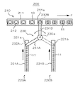
次に、添付図面を参照して本発明に係る給材組込装置及び電子機器の製造方法の実施形態について詳細に説明する。図1は本実施形態の給材組込装置200の全体構成を模式的に示す概略構成図、図2は給材組込装置200の主要部を模式的に示す概略部分平面図である。この給材組込装置200は、組込対象物10を搬送する搬送手段210と、第1部品供給部220A及び第2部品供給部220Bを備えた部品供給手段と、第1部品組込部230A及び第2部品組込部230Bを備えた部品組込手段230とを有する。
【0023】
搬送手段210は、たとえば、搬送路211に沿ってパレット212を移動させることができるように構成され、パレット212は組込対象物10を搭載している。組込対象物10としては、たとえば、給材組込装置200が時計の製造ラインで用いられる場合には時計のムーブメントや時計ケースなどが挙げられる。また、搬送路211に沿ってパレット212(組込対象物10)を移動させる移動機構としては、ベルトコンベア、ローラコンベア、振動コンベア、空気コンベアなどの種々のコンベアを用いることができる。
【0024】
部品供給手段の第1部品供給部220A及び第2部品供給部220Bは、図示例では、それぞれ部品供給機によって構成される。この部品供給機としては、たとえば、公知のパーツフィーダを用いることができる。図示例では、振動式のボウル型パーツフィーダを用いている。第1部品供給部220A及び第2部品供給部220Bは、部品11を所定の部品供給路221A,221Bに供給する。より具体的には、部品11を一定の姿勢で整列させた状態で部品供給路221A,221Bに搬送するようになっている。また、部品11は、部品供給路221A,221Bの下流端に設定された部品供給位置221a,221bまで搬送された状態で停止するようになっている。
【0025】
部品組込手段230には、第1部品組込部230Aと、第2部品組込部230Bとが設けられている。第1部品組込部230Aには、アーム231Aと、このアーム231Aに対して取り付けられた部品把持部232Aが設けられている。また、第2部品組込部230Bには、アーム231Bと、このアーム231Bに対して取り付けられた部品把持部232Bが設けられている。具体的には、アーム231A及び231Bは垂直な回動軸線230aを中心に回動するように構成され、部品把持部232A,232Bはそれぞれに取り付けられたアーム231A,231Bに対して昇降可能に構成されている。
【0026】
この給材組込装置200では、アーム231A及び231Bが回動軸線230aの周りに正逆方向に交互に回動しながら、部品11を組込対象物10に次々と組み込んでいく。より具体的には、図2に示すように、部品把持部232Aが部品供給位置221a上の部品11を把持しているときに、部品把持部232Bは搬送路211上の部品組込位置211aにおいて組込対象物10に部品11を組み込む。その後、アーム231A,231Bが時計回りに回動して、部品把持部232Bが部品供給位置221b上の部品11を把持しているときに、部品把持部232Aは上記部品組込位置211aにおいて上記の次に搬送路211上を搬送されてきた組込対象物10に部品11を組み込む。さらにその後、アーム231A,231Bは反時計回りに回動し、図2に示すもとの姿勢に戻る。
【0027】
給材組込装置200は、上記の動作を繰り返しながら、搬送路211に沿って搬送されてくる複数の組込対象10に対して順次に第1部品組込部230Aと第2部品組込部230Bとが交互に部品11を組み込んでいくようになっている。
【0028】
図3は、上記給材組込装置200の制御駆動系の構成を模式的に示す概略構成図である。この給材組込装置200は、制御部200Cにより上記部品組込手段230が制御駆動されるように構成されている。制御部200Cは、たとえば、マイクロプロセッサユニットやプログラマブルコントローラなどによって構成される。
【0029】
なお、上記搬送手段210が制御部200Cによって制御駆動されるように構成されてもよい。たとえば、搬送手段210は、部品組込位置211aに配置された組込対象物10に部品11が組み込まれたことを検出器210sによって検出したときに、当該組込対象物10を搬送路211の下流側に送り出すとともに、上流側にある次の組込対象物10を部品組込位置211aに配置するように構成されていればよい。しかし、この搬送手段210を制御部200Cによって制御駆動することにより、より確実に組込対象物10への部品の組込を行うことができる。たとえば、部品組込手段230の部品把持部232A,232Bによって実際に部品11が組み込まれたことを検出してから、搬送手段210が組込対象物10を送るといった具合である。
【0030】
また、上記部品供給手段も制御部200Cによって制御駆動されるように構成されてもよい。たとえば、部品供給手段の第1部品供給部220A及び第2部品供給部220Bはそれぞれ独立して部品11を部品供給位置221a及び221Bに供給するように構成することができる。しかし、制御部200Cによって部品供給手段を制御駆動することによって、たとえば、搬送手段210及び部品組込手段230による組込対象物10に対する部品11の組込状態に合わせて部品供給手段の部品供給速度を調整することが可能になる。
【0031】
制御部200Cは、第1部品供給部220Aの部品供給位置221aに部品11が供給されているか否かを検出する検出器220As、及び、第2部品供給部220Bの部品供給位置221bに部品11が供給されているか否かを検出する検出器220Bsからそれぞれ検出信号を受けるように構成されている。また、制御部200Cは、搬送手段210の部品組込位置211aに組込対象物10が配置されているか否かを検出する検出器210sからの検出信号を受けるように構成されている。さらに、制御部200Cは、部品組込手段230の第1部品組込部230Aの部品把持部232Aに部品11が把持されているか否かを検出する検出器230As、及び、第2部品組込部230Bの部品把持部232Bに部品11が把持されているか否かを検出する検出器230Bsからそれぞれ検出信号を受けるように構成されている。
【0032】
制御部200Cは、上記各検出器から受けた検出信号に応じて、部品組込手段230の各部に制御信号を出力するように構成されている。具体的には、制御部200Cは、第1駆動回路230ADに制御信号を出力し、この制御信号に応じて、第1駆動回路230ADは部品把持部232Aを昇降動作させる昇降駆動源230AM及び部品把持部232Aの部品11の把持動作を行う把持駆動源230APに駆動信号を送出する。また、制御部200Cは、第2駆動回路230BDに制御信号を出力し、この制御信号に応じて第2駆動回路230BDは部品把持部232Bを昇降動作させる昇降駆動源230BM及び部品把持部232Bの把持動作を行う把持駆動源230BPに駆動信号を送出する。さらに、制御部200Cは、第3駆動回路230CDに制御信号を出力し、この制御信号に応じて第3駆動回路230Cは回動駆動源230CMに駆動信号を送出する。ここで、回動駆動源230CMは、上記アーム231A,231Bを回動させるための回動駆動機構230Cを駆動するための手段(電動モータや流体圧装置など)である。
【0033】
次に、上記のように構成された給材組込装置200の詳細な動作手順について図4に示す概略フローチャートに従って説明する。
【0034】
最初に、上記の部品把持部232Aが部品供給位置221a上に配置され、部品把持部232Bが部品組込位置211a上に配置されているとする。このとき、上記の制御部200Cは、パレット212(組込対象物10)が上記部品組込位置211aに配置されていることを検出するまで待機する。組込対象物10が部品組込位置211aに配置されると、次に、部品供給位置221aに部品11が供給されているか否か、及び、部品把持部232Bに部品11が把持されているか否かが検出される。部品供給位置221aに部品11が配置されている場合には、部品把持部232Aは下降し、部品11を把持し、上昇する。部品供給位置221aに部品11が配置されていない場合(すなわち第1部品供給部220Aに何らかの異常がある場合)には、部品把持部232Aは動作しない。また、部品把持部232Bに部品11が把持されている場合には、部品把持部232Bは下降し、部品11を組込対象物10に組み込み、上昇する。また、上記の動作前に部品把持部232Bが部品11を把持していない場合には、部品把持部232Bは動作しない。
【0035】
上記の動作が完了すると、上記回転駆動機構230Cが動作してアーム231A,231Bは回動し、これによって、部品把持部232Aが部品組込位置211a上に配置され、部品把持部232Bが部品供給位置221b上に配置された状態になる。また、図示しないが、部品組込位置211a上に配置された組込対象物10に上記部品把持部232Bによって部品11が組み込まれた場合には、上記の動作後に、当該組込対象物10は搬送路211の下流側に移動し、次の組込対象物10が部品組込位置211aに搬送されてくる。また、部品把持部232Bによる部品11の組み込みが行われなかった場合には、そのまま当該組込対象物10は移動しない。
【0036】
次に、再び組込対象物10が部品組込位置211aに配置されているか否かが検出され、組込対象物10が部品組込位置211aに配置されていない場合には、組込対象物10が部品組込位置211aに配置されるまで待機する。組込対象物10が部品組込位置211aに配置されると、次に、部品供給位置221bに部品11が供給されているか否か、及び、部品把持部232Aに部品11が把持されているか否かが検出される。部品供給位置221bに部品11が配置されている場合には、部品把持部232Bは下降し、部品11を把持し、上昇する。部品供給位置221bに部品11が配置されていない場合(すなわち第2部品供給部220Bに何らかの異常がある場合)には、部品把持部232Bは動作しない。また、部品把持部232Aに部品11が把持されている場合には、部品把持部232Aは下降し、部品11を組込対象物10に組み込み、上昇する。また、上記の動作前に部品把持部232Aが部品11を把持していない場合には、部品把持部232Aは動作しない。
【0037】
上記の動作が完了すると、上記回転駆動機構230Cが動作してアーム231A,231Bは上記とは逆方向に回動し、これによって、部品把持部232Bが部品組込位置211a上に配置され、部品把持部232Aが部品供給位置221a上に配置された状態になる。また、図示しないが、部品組込位置211a上に配置された組込対象物10に上記部品把持部232Aによって部品11が組み込まれた場合には、上記の動作後に、当該組込対象物10は搬送路211の下流側に移動し、次の組込対象物10が部品組込位置211aに搬送されてくる。また、部品把持部232Aによる部品11の組み込みが行われなかった場合には、そのまま当該組込対象物10は移動しない。
【0038】
上述のような動作手順は、装置が稼動している限り繰り返し行われる。通常は、第1部品供給部220A及び第2部品供給部220Bが正常に動作するので、一方の部品把持部が部品供給位置にて部品11を把持し、他方の部品把持部が部品組込位置211aにて部品11を組込対象物10に組み込むといった動作が交互に行われる。このとき、一方の部品供給部に異常が生じて部品供給が途絶えると、他方の部品供給部により供給された部品11のみが組込対象物10に組み込まれるが、部品の組込作業自体は継続して行われる。
【0039】
上記のように、第1部品供給部220A又は第2部品供給部220Bのうちの一方において部品供給位置221a,221bに部品11が供給されなくなると、検出器220As,220Bsによって報知手段がこれを報知するようになっている。ここで、報知手段としては、警報音などを出力する発音手段(ブザー、スピーカなど)、警報表示などを表示する表示手段(警報ランプの点灯や点滅など)が挙げられる。これらは、給材組込装置200自体に設置されていてもよく、また、コントロール室に設置されていてもよく、或いは、作業者等に携帯されていてもよい。このような報知手段によって作業者等は異常の発生した供給装置を整備する。部品供給の異常が回復すると、上記動作手順によれば、そのまま何らの操作を行うことなく正常状態に復帰することができる。
【0040】
図5は、本実施形態の部品組込手段230の詳細な構造を示す平面図(a)及び正面図(b)である。なお、図5(a)の平面図においては、部品組込手段230が図1及び図2と同じ回動姿勢にある状態を示すが、図5(b)の正面図においては、部品組込手段230が回動途中にある状態を示してある。
【0041】
部品組込手段230に設けられる第1部品組込部230A及び第2部品組込部230Bには、それぞれ、部品把持部232A,232Bを先端に取り付けた昇降軸233A,233Bが設けられ、これらの昇降軸233A,233Bがアーム231A及び231Bを一体的に備えた回動部材231によって回転自在に保持された状態となっている。昇降軸233A,233Bの上部にはプーリ部234A,234Bが設けられ、これらのプーリ部234A,234Bには、合成ゴムなどで構成された伝達ベルト234d,234eが架設されている。また、昇降軸233Aと233Bとの間には回動軸体235が配置され、この回動軸体235は上記回動部材231の中央部に取り付け固定されている。この回動軸体235の中心軸線は、図1及び図2に示す回動軸線230aである。
【0042】
回動軸体235は、固定された支持部材236に対して回転自在に軸支されている。支持部材236は、上部に設けられた板状部と、この板状部から回動軸体235に沿って下方に伸びる筒状部とを備えている。この筒状部の外周にはプーリ部236Cが設けられ、このプーリ部236Cには、上記伝達ベルト234d,234eが架設されている。すなわち、上記の伝達ベルト234d,234eは、上記プーリ部234A,234Bとプーリ部236Cとに架設されている。支持部材236の筒状部には、昇降軸233A,233Bの降下時の下限を規制するストッパ236A,236Bが設けられている。
【0043】
なお、昇降軸233A,233Bには、規制ピン233a,233bが取り付けられている。また、回動部材231(アーム231A,231B)には取付部材231cが取り付けられ、この取付部材231cにはストッパ231d(調整ねじ)が調整可能に取り付けられている。上記の規制ピン233a,233bは、上記昇降軸233A,233Bがそれぞれ上記の伝達ベルト234d,234eにより回転駆動されたとき、所定の回転角度でストッパ231dに規制されることにより、昇降軸233A,233Bの回転姿勢が規定されるようになっている。
【0044】
支持部材236の板状部には、上記の部品供給位置221aに対応する角度位置に昇降駆動手段237Aが取り付けられ、上記の部品供給位置221bに対応する角度位置に昇降駆動手段237Bが取り付けられ、さらに、上記の部品組込位置211aに対応する角度位置に昇降駆動手段237Cが取り付けられている。これらの昇降駆動手段237A,237B,237Cは、それぞれの位置に回動してきた昇降軸233A,233Bを上方から押し下げるように作用する。なお、昇降軸233A,233Bは、昇降駆動手段237A,237B,237Cによる押圧力に対抗する復帰力を常に受けた状態となっており、この復帰力により昇降駆動手段の押圧力が解除されると図示の状態(高さ)に復帰するように構成されている。この復帰力はばねなどの弾性部材によって生ずる。
【0045】
回動軸体235にはプーリ部238が設けられ、このプーリ部238は、回動駆動源230CM(図3参照)を内蔵する回動駆動部239のプーリ部239aに対して伝達ベルト238dを介して連結されている。これによって、回動駆動部239に内蔵された回動駆動源が動作すると、伝達ベルト238dを介して回動軸体235が回転駆動される。
【0046】
上記のように回動軸体235が回転駆動されると、回動部材231(アーム231A,231B)を介して昇降軸233A,233Bが回動し、部品把持部232A,232Bが上述のように移動する。また、このとき、伝達ベルト234d,234eを介して昇降軸233A,233Bが回転することによって、支持部材236の筒状部に設けられたプーリ236Cに架設された伝達ベルト234d,234eによって昇降軸233A,233Bが回転され、この昇降軸233A,233Bの回転は、やがて規制ピン233a,233bがストッパ231dによって停止される。このような伝達ベルト234d,234eによる昇降軸233A,233Bの回転により、部品把持部232A,232Bは、上記回動動作による姿勢変化がほとんどなくなるように構成されている。実際には、プーリ236Cの径がプーリ234A,234Bよりも大きいことにより、昇降軸233A,233Bの回転角は、回動部材231の回動角よりも大きくなるように構成されているが、規制ピン233a,233bとストッパ231dによって昇降軸233A,233Bの回転が規制されるため、部品把持部232A,232Bの回動動作による姿勢変化がほとんどなくなるように構成されている。なお、伝達ベルト234d,234eによる部品把持部232A,232Bの姿勢制御は、上記とは異なり、種々の態様で行われ得る。たとえば、部品供給位置221a,221Bに供給された部品11の姿勢と、部品組込位置211aに組み込まれるべき部品11の姿勢との間の関係は装置構成によって様々であるので、部品把持部233A,233Bの回動動作による姿勢変化をなくす場合に限らず、却ってある程度の姿勢変化が要求される場合もあるからである。たとえば、図示例とは異なり、プーリ236Cとプーリ234A,234Bとの間に伝達ベルト234d,234eを8の字状になるように架設してもよい。
【0047】
本実施形態の上記給材組込装置200は、特に、時計部品をムーブメントや時計ケースに組み込む場合に用いることができる。この場合、時計部品としては、地板、輪列受け、ステータ(ステッピングモータや小型発電機の部品)、かんぬき、電池プラス端子、歯車、日車や曜車などの表示車、文字盤、太陽電池、回転錘、ステッピングモータ、小型発電機などが挙げられる。そして、これらの時計部品を上記方法によってムーブメントに組み込むことによって、時計の製造効率を高めることができ、最終的には製造コストを低減することができる。
【0048】
尚、本発明の給材組込装置及び時計の製造方法は、上述の図示例にのみ限定されるものではなく、本発明の要旨を逸脱しない範囲内において種々変更を加え得ることは勿論である。たとえば、上記実施形態では、電子機器の一例として時計を例示したが、本発明は時計に限らず、各種の電子機器に適用することができる。特に、腕時計などの携帯型電子機器に適用する場合に効果的である。
【図面の簡単な説明】
【図1】実施形態の給材組込装置の全体構成を模式的に示す概略斜視図。
【図2】実施形態の給材組込装置の主要部を模式的に示す概略平面図。
【図3】実施形態の給材組込装置の制御駆動系を示す概略構成図。
【図4】実施形態の動作手順を示す概略フローチャート。
【図5】実施形態の部品組込手段の構造を示す概略平面図(a)及び正面図(b)。
【図6】従来の給材組込装置の概略構成を示す概略平面図。
【符号の説明】
10…組込対象物(ムーブメント)、11…部品、200…給材組込装置、200C…制御部、210…搬送手段、211…搬送路、211a…部品組込位置、212…パレット、220…部品供給手段、220A…第1部品供給部、220B…第2部品供給部、221A,221B…部品供給位置、230…部品組込手段、230A…第1部品組込部、230B…第2部品組込部、231…回動部材、231A,231B…アーム、231c…取付部材、231d…ストッパ、232A,232B…部品把持部、233A,233B…昇降軸、233a,233b…規制ピン、234A,234B,236C,238…プーリ部、234d,234e,238d…伝達ベルト、235…回軸動体、236…支持部材、236a,236b…ストッパ、237A,237B,237C…昇降駆動手段、239…回動駆動部[0001]
TECHNICAL FIELD OF THE INVENTION
The present invention relates to a material assembling apparatus and a method of manufacturing an electronic device, and more particularly to an assembling technique of a product which is suitable when components are incorporated into an object to be incorporated at high speed.
[0002]
[Prior art]
2. Description of the Related Art Generally, in an automatic assembly line for various products, shortening of assembling time and speeding up of assembling work are progressing in order to reduce assembling cost. As a method of responding to the speeding up of assembly, conventionally, a plurality of component supply machines having a low supply capacity are provided, and a plurality of component assembling mechanisms corresponding to the plurality of component supply machines are installed. By performing the assembling work, the speed of the assembling work was increased.
[0003]
For example, FIG. 6 shows a main part of a conventional
[0004]
In this apparatus, the
[0005]
Further, although the configuration is different from that of the above-described device, the following
[0006]
[Patent Document 1]
JP-A-5-220634
[Patent Document 2]
JP-A-6-31550
[0007]
[Problems to be solved by the invention]
However, the above-described conventional
[0008]
In addition, since the number of component feeders and component assemblers increases, maintenance work such as maintenance and inspection increases, resulting in a problem that human costs increase. Further, there is a problem that the installation space of the apparatus increases.
[0009]
Therefore, the present invention is to solve the above-mentioned problem, and its object is to increase the speed of the assembling work, reduce the frequency of stopping the production line, and effectively improve the productivity as a whole. And a method for manufacturing an electronic device.
[0010]
[Means for Solving the Problems]
In order to solve the above problems, the material assembling device of the present invention is provided with a conveying unit that conveys an object to be incorporated, and the assembling object that has been conveyed to a predetermined component incorporating position by the conveying unit. And a component supplying means for supplying and incorporating the component to the component incorporating means, wherein the component supplying means includes first component supplying means, A second component supply unit, wherein the component assembling unit transfers the component supplied by the first component supply unit to the component assembling position and incorporates the component into the assembling target. A component assembling unit; and a second component assembling unit that transfers the component supplied by the second component supply unit to the component assembling position and incorporates the component into the assembling target. The part assembling part and the second part assembling part are operated alternately. Characterized in that it is configured to be built the component alternately by a common said component built located successively conveying said group of write object coming being by the transport means.
[0011]
According to the present invention, the first component assembling section and the second component assembling section for supplying components to the same component assembling position are provided, and the first and second component assembling sections are provided. By performing the operations alternately, the parts can be incorporated into the object to be assembled at high speed. In this case, since the two component assembling units are configured to transfer and incorporate components to a common component assembling position, even if the component supply by one component supply unit is interrupted, the other component assembling unit is stopped. By operating only the component assembling unit corresponding to the component supply unit, it is possible to continue to incorporate components without stopping the transporting means in the apparatus configuration, so that the operation rate can be improved.
[0012]
For example, in the conventional device configuration, two component assembling machines are configured to operate at different component assembling positions. If the road is not stopped, there is a risk that an installation target, for which the assembly operation of the components has not been completed, may flow to the downstream side of the line. On the other hand, in the present invention, since the two component incorporating units are originally configured to alternately incorporate components at the common component incorporating position, even if the component supply by one component supplying unit is interrupted, On the side of the transfer means for transferring the object to be mounted, the transfer by the transfer means only needs to be stopped until the operation of mounting the components is performed, and there is no need to perform particularly complicated control.
[0013]
In this case, it is conceivable that the assembling speed of the entire apparatus is reduced by an amount that one of the component supply unit and the component assembling unit does not operate. Can be dealt with by interruption of the supply of one part only by synchronizing the components, it is not necessary to stop the entire production line.
[0014]
Further, since the two component assembling units alternately perform the assembling operation at the common component assembling position, the area occupied by the component assembling means including the two component assembling units can be reduced.
[0015]
In addition, the present invention includes not only a case where two component incorporating units incorporate components at the common component incorporating position, but also a case where three or more component incorporating units are configured to incorporate components. I do.
[0016]
In the present invention, when component supply to the first component incorporation unit by the first component supply unit or component supply to the second component incorporation unit by the second component supply unit is interrupted, component supply is stopped. It is preferable that the configuration is such that the incorporation of the component is continued by the continued second component incorporation unit or the first component incorporation unit. Thus, the components can be continuously incorporated without stopping the production line. In this case, it is preferable that the notification unit be activated when the component supply by one component supply unit is interrupted. If the worker who has noticed the abnormality of the component supply by the notification means eliminates the defect of one of the component supply units, the operation can be shifted to the normal operation as it is.
[0017]
In the present invention, it is preferable that the first component assembling portion and the second component assembling portion are configured to be integrally rotatable around a common rotation axis. According to this, the component assembling means can be configured simply and compactly.
[0018]
In the present invention, the first component assembling unit and the second component assembling unit may include a posture rotation unit configured to change a gripping posture of the component in accordance with a rotation angle around the rotation axis. Is preferred. According to this, since the orientation of the component can be controlled by the attitude rotating means in accordance with the positional relationship between the first component supply unit and the second component supply unit and the component installation position, for example, the first The component mounting posture of the component mounting unit and the component mounting posture of the second component mounting unit can be made equal to each other at the component mounting position. This leads to being able to control the component installation posture at the component installation position according to the relationship between the component supply posture by the first component supply unit and the component supply posture by the second component supply unit. The degree of freedom in designing the device configuration can be increased.
[0019]
Next, according to the method for manufacturing an electronic device of the present invention, there is provided a transporting unit for transporting an assembly target, and supplying a component to the assembly target transported to a predetermined component integration position by the transporting unit. In a method of manufacturing an electronic device using component incorporation means for incorporating and incorporating, and component supply means for supplying the component to the component incorporation means, the component supply means includes a first component supply unit and a third component supply unit. A two-component supply unit, wherein the component incorporation means includes a first component incorporation unit that transfers the component supplied by the first component supply unit to the component incorporation position and incorporates the component into the incorporation target And a second component incorporation unit for transferring the component supplied by the second component supply unit to the component incorporation position and incorporating the component into the object to be incorporated, and the first component incorporation unit And the second component assembling section are alternately operated by the transporting means. And wherein the incorporation of the alternating component in common of the component built-position to the group write object coming sequentially conveyed Te.
[0020]
ADVANTAGE OF THE INVENTION According to this invention, while being able to assemble electronic equipment at high speed, the stop frequency of a production line can be reduced. Further, the installation space of the manufacturing apparatus can be reduced. In this case, examples of the object to be incorporated include a movement and a case. In this case, the components of the electronic device include a main plate, a train wheel receiver, a stator, a bolt, a battery plus terminal, a gear, a display wheel, a dial, a middle frame, and a back cover.
[0021]
In the present invention, when component supply to the first component incorporation unit by the first component supply unit or component supply to the second component incorporation unit by the second component supply unit is interrupted, component supply is stopped. It is preferable that the incorporation of the component be continued by the continued second component incorporation unit or the first component incorporation unit.
[0022]
BEST MODE FOR CARRYING OUT THE INVENTION
Next, with reference to the accompanying drawings, an embodiment of a material incorporating device and a method of manufacturing an electronic device according to the present invention will be described in detail. FIG. 1 is a schematic configuration diagram schematically illustrating the overall configuration of the
[0023]
The
[0024]
In the illustrated example, the first
[0025]
The
[0026]
In the material
[0027]
The material
[0028]
FIG. 3 is a schematic configuration diagram schematically showing the configuration of a control drive system of the material
[0029]
Note that the
[0030]
Further, the component supply unit may be configured to be controlled and driven by the
[0031]
The
[0032]
The
[0033]
Next, a detailed operation procedure of the
[0034]
First, it is assumed that the
[0035]
When the above operation is completed, the rotation drive mechanism 230C operates to rotate the
[0036]
Next, it is detected again whether or not the
[0037]
When the above operation is completed, the rotation drive mechanism 230C operates to rotate the
[0038]
The above-described operation procedure is repeatedly performed as long as the apparatus is operating. Normally, the first
[0039]
As described above, when the
[0040]
FIG. 5 is a plan view (a) and a front view (b) showing the detailed structure of the component assembling means 230 of the present embodiment. Note that the plan view of FIG. 5A shows a state in which the component assembling means 230 is in the same rotation posture as in FIGS. 1 and 2, but the front view of FIG. The state where the
[0041]
The first
[0042]
The
[0043]
In addition, regulating
[0044]
Elevating drive means 237A is attached to the plate-like portion of the
[0045]
A
[0046]
When the
[0047]
The above-described
[0048]
It should be noted that the method of manufacturing the material incorporating device and the timepiece of the present invention is not limited to the illustrated example described above, and it is needless to say that various changes can be made without departing from the gist of the present invention. . For example, in the above-described embodiment, a timepiece is illustrated as an example of the electronic device. However, the present invention is not limited to a timepiece and can be applied to various electronic devices. In particular, it is effective when applied to a portable electronic device such as a wristwatch.
[Brief description of the drawings]
FIG. 1 is a schematic perspective view schematically showing the overall configuration of a material supplying apparatus according to an embodiment.
FIG. 2 is a schematic plan view schematically showing a main part of the material supplying apparatus according to the embodiment.
FIG. 3 is a schematic configuration diagram showing a control drive system of the material incorporating device according to the embodiment.
FIG. 4 is a schematic flowchart showing an operation procedure of the embodiment.
FIG. 5 is a schematic plan view (a) and a front view (b) showing the structure of the component assembling means of the embodiment.
FIG. 6 is a schematic plan view showing a schematic configuration of a conventional material supply device.
[Explanation of symbols]
DESCRIPTION OF
Claims (6)
前記部品供給手段には第1部品供給部及び第2部品供給部が設けられ、
前記部品組込手段には、前記第1部品供給部によって供給された前記部品を前記部品組込位置に移載して前記組込対象物に組み込む第1部品組込部と、前記第2部品供給部によって供給された前記部品を前記部品組込位置に移載して前記組込対象物に組み込む第2部品組込部とが設けられ、
前記第1部品組込部と前記第2部品組込部とを交互に動作させて、前記搬送手段によって順次搬送されてくる前記組込対象物に共通の前記部品組込位置にて交互に前記部品を組み込み可能に構成されていることを特徴とする給材組込装置。Conveying means for conveying the object to be assembled, component embedding means for supplying and embedding components to the object to be embodyed which has been conveyed to a predetermined part embedding position by the conveying means, and the part embedding means A material supply device having component supply means for supplying the component to
The component supply means includes a first component supply unit and a second component supply unit,
The component assembling means includes: a first component assembling unit that transfers the component supplied by the first component supply unit to the component assembling position and incorporates the component into the assembly target; A second component assembling unit that transfers the component supplied by a supply unit to the component assembling position and incorporates the component into the assembling target;
The first component assembling unit and the second component assembling unit are operated alternately to alternately operate at the component assembling position common to the assembling target sequentially transported by the transporting means. A material assembling apparatus characterized in that parts can be incorporated therein.
前記部品供給手段には、第1部品供給部及び第2部品供給部を設け、
前記部品組込手段には、前記第1部品供給部によって供給された前記部品を前記部品組込位置に移載して前記組込対象物に組み込む第1部品組込部と、前記第2部品供給部によって供給された前記部品を前記部品組込位置に移載して前記組込対象物に組み込む第2部品組込部とを設け、
前記第1部品組込部と前記第2部品組込部とを交互に動作させて、前記搬送手段によって順次搬送されてくる前記組込対象物に共通の前記部品組込位置にて交互に前記部品を組み込むことを特徴とする電子機器の製造方法。Conveying means for conveying the object to be assembled, component embedding means for supplying and embedding components to the object to be embodyed which has been conveyed to a predetermined part embedding position by the conveying means, and the part embedding means In a method for manufacturing an electronic device using component supply means for supplying the component to the
The component supply means includes a first component supply unit and a second component supply unit,
The component assembling means includes: a first component assembling unit that transfers the component supplied by the first component supply unit to the component assembling position and incorporates the component into the assembly target; A second component assembling unit that transfers the component supplied by the supply unit to the component assembling position and incorporates the component into the assembly target;
The first component assembling unit and the second component assembling unit are operated alternately to alternately operate at the component assembling position common to the assembling target sequentially transported by the transporting means. A method for manufacturing an electronic device, comprising incorporating components.
Priority Applications (1)
| Application Number | Priority Date | Filing Date | Title |
|---|---|---|---|
| JP2003080708A JP2004283982A (en) | 2003-03-24 | 2003-03-24 | Manufacturing method of supply material incorporating device and electronic device |
Applications Claiming Priority (1)
| Application Number | Priority Date | Filing Date | Title |
|---|---|---|---|
| JP2003080708A JP2004283982A (en) | 2003-03-24 | 2003-03-24 | Manufacturing method of supply material incorporating device and electronic device |
Publications (1)
| Publication Number | Publication Date |
|---|---|
| JP2004283982A true JP2004283982A (en) | 2004-10-14 |
Family
ID=33294491
Family Applications (1)
| Application Number | Title | Priority Date | Filing Date |
|---|---|---|---|
| JP2003080708A Withdrawn JP2004283982A (en) | 2003-03-24 | 2003-03-24 | Manufacturing method of supply material incorporating device and electronic device |
Country Status (1)
| Country | Link |
|---|---|
| JP (1) | JP2004283982A (en) |
Cited By (3)
| Publication number | Priority date | Publication date | Assignee | Title |
|---|---|---|---|---|
| JP2007222977A (en) * | 2006-02-22 | 2007-09-06 | Ricoh Co Ltd | Part assembling device |
| KR101162643B1 (en) | 2009-10-30 | 2012-07-04 | 주식회사 조인탑 | Apparatus amd method of assembling jaw for pipe joint |
| JP2018524971A (en) * | 2015-05-19 | 2018-09-06 | アール・エイ・アイ・ストラテジック・ホールディングス・インコーポレイテッド | Method for assembling cartridges for smoking articles, and related systems and devices |
-
2003
- 2003-03-24 JP JP2003080708A patent/JP2004283982A/en not_active Withdrawn
Cited By (4)
| Publication number | Priority date | Publication date | Assignee | Title |
|---|---|---|---|---|
| JP2007222977A (en) * | 2006-02-22 | 2007-09-06 | Ricoh Co Ltd | Part assembling device |
| JP4601563B2 (en) * | 2006-02-22 | 2010-12-22 | 株式会社リコー | Parts assembly device |
| KR101162643B1 (en) | 2009-10-30 | 2012-07-04 | 주식회사 조인탑 | Apparatus amd method of assembling jaw for pipe joint |
| JP2018524971A (en) * | 2015-05-19 | 2018-09-06 | アール・エイ・アイ・ストラテジック・ホールディングス・インコーポレイテッド | Method for assembling cartridges for smoking articles, and related systems and devices |
Similar Documents
| Publication | Publication Date | Title |
|---|---|---|
| US8154304B2 (en) | PCB delivery apparatus PCB testing system employing the same | |
| CN101547592B (en) | Installation head actuator for electronic parts and installation device for electronic parts | |
| US7987742B2 (en) | Transportation apparatus and tension adjustment method of belt in the same | |
| CN101938894B (en) | Apparatus for conveying electronic element | |
| CN101437718B (en) | Device for machining components of a vehicle body | |
| EP3064455A1 (en) | Conveyor device | |
| JP2004283982A (en) | Manufacturing method of supply material incorporating device and electronic device | |
| CN205726881U (en) | A kind of inserter conveyer device | |
| JP3599286B2 (en) | Discharge device for sorting conveyor | |
| KR20180125134A (en) | The driving device for changing the direction of conveyor | |
| JP5818241B2 (en) | Spherical drive module and transfer device using the same | |
| CN212064766U (en) | Swing mechanism and synchronous transmission driving device | |
| WO2014098115A1 (en) | Workpiece conveyance device, and workpiece conveyance method | |
| CN216425907U (en) | Steering conveyor | |
| WO2007063595A1 (en) | Manufacturing system | |
| CN110092166A (en) | A kind of filler strip sorter | |
| CN219383756U (en) | Feeding machine | |
| TWI405702B (en) | Conveying system | |
| CN110814960A (en) | Automatic production line for grinding outer arc of non-equal-thickness drum brake pad and control method thereof | |
| CN111959868A (en) | Transmission device | |
| JP5969434B2 (en) | Element array device and element array method | |
| KR20040110154A (en) | Mechanism for driving nozzles of chip mounter | |
| JP2011120545A (en) | Welsh onion cutting apparatus | |
| CN212314640U (en) | Balance wheel sorting equipment | |
| CN211732999U (en) | Transmission separation device and transfer equipment with same |
Legal Events
| Date | Code | Title | Description |
|---|---|---|---|
| A621 | Written request for application examination |
Free format text: JAPANESE INTERMEDIATE CODE: A621 Effective date: 20060320 |
|
| RD04 | Notification of resignation of power of attorney |
Free format text: JAPANESE INTERMEDIATE CODE: A7424 Effective date: 20070403 |
|
| A977 | Report on retrieval |
Free format text: JAPANESE INTERMEDIATE CODE: A971007 Effective date: 20080311 |
|
| A131 | Notification of reasons for refusal |
Free format text: JAPANESE INTERMEDIATE CODE: A131 Effective date: 20080318 |
|
| A761 | Written withdrawal of application |
Free format text: JAPANESE INTERMEDIATE CODE: A761 Effective date: 20080515 |