JP2004282984A - Electric cable laying method - Google Patents
Electric cable laying method Download PDFInfo
- Publication number
- JP2004282984A JP2004282984A JP2003300195A JP2003300195A JP2004282984A JP 2004282984 A JP2004282984 A JP 2004282984A JP 2003300195 A JP2003300195 A JP 2003300195A JP 2003300195 A JP2003300195 A JP 2003300195A JP 2004282984 A JP2004282984 A JP 2004282984A
- Authority
- JP
- Japan
- Prior art keywords
- wire
- rope
- transmission line
- pulleys
- wheel
- Prior art date
- Legal status (The legal status is an assumption and is not a legal conclusion. Google has not performed a legal analysis and makes no representation as to the accuracy of the status listed.)
- Granted
Links
- 238000000034 method Methods 0.000 title claims abstract description 20
- 238000010276 construction Methods 0.000 claims description 9
- 230000005540 biological transmission Effects 0.000 abstract description 71
- 229910000831 Steel Inorganic materials 0.000 abstract description 34
- 239000010959 steel Substances 0.000 abstract description 34
- 239000000725 suspension Substances 0.000 description 15
- 239000012212 insulator Substances 0.000 description 5
- 230000000694 effects Effects 0.000 description 3
- 229920000271 Kevlar® Polymers 0.000 description 2
- 239000004761 kevlar Substances 0.000 description 2
- 125000006850 spacer group Chemical group 0.000 description 2
- 238000004804 winding Methods 0.000 description 2
- 239000000463 material Substances 0.000 description 1
- 239000002184 metal Substances 0.000 description 1
- 238000005491 wire drawing Methods 0.000 description 1
Images


Landscapes
- Electric Cable Installation (AREA)
Abstract
Description
本発明は鉄塔等の支持物に電線を架線(移線を含む)する架線工法に関し、特に、架線に際して電線の弛みを少なくすることができる架線工法に関するものである。 The present invention relates to an overhead wire construction method for wiring (including transfer) an electric wire to a support such as a steel tower, and more particularly to an overhead wire construction method capable of reducing slack of an electric wire during overhead wiring.
従来、移線を行う一の既設鉄塔と新設鉄塔との間に主索(親ワイヤ)を張り渡し、その主索に沿って移動可能とされた金車に設けた支持滑車で架線を支持し、その状態で一の既設鉄塔から新設鉄塔まで金車を移動させることにより、移線を行う移線工法がある。これにより、作業者が熟練を要する者でなくとも、安全、かつ確実に移線をすることができる。(例えば特許文献1)
また、低弛度の架空電線の架線方法として、鉄塔間に機械的強度の大きい鋼撚線を架線し、この鋼撚線に吊金車を所定数載架し、前記吊金車に電線を挿通し延線した状態で前記鋼撚線に電線を絶縁スペーサを介して添架し、その後、吊金車を取り外す方法がある。(例えば特許文献2)
この架線方法によれば、電線の各部分を所定数の吊金車で鋼撚線に吊り下げた状態で、鋼撚線に電線を絶縁スペーサを介して添架するので、電線を鉄塔間に架線する場合の電線の弛みを少なくすることができる。
Conventionally, a main rope (parent wire) is stretched between one existing tower and a new tower to perform the transfer, and the overhead wire is supported by a support pulley provided on a pulley that is movable along the main rope. In this state, there is a wire transfer method in which a wire wheel is moved from one existing tower to a new tower to perform a transfer. Thereby, even if an operator is not a person who needs skill, it is possible to safely and reliably perform the transfer. (For example, Patent Document 1)
In addition, as a method of wiring an overhead electric wire with low sag, a steel stranded wire having high mechanical strength is laid between steel towers, a predetermined number of suspension wheels are mounted on the steel stranded wire, and the electric wire is connected to the suspension wheel. There is a method in which an electric wire is attached to the steel stranded wire via an insulating spacer in a state where the wire is inserted and extended, and then the hanging wheel is removed. (For example, Patent Document 2)
According to this overhead wire method, since each part of the electric wire is suspended on the steel stranded wire by a predetermined number of suspension wheels, and the electric wire is attached to the steel stranded wire via the insulating spacer, the electric wire is connected between the steel towers. In this case, the slack of the electric wire can be reduced.
しかし、上述の特許文献1記載の移線工法では、移線される電線の一箇所のみを支持滑車で支えつつ移線するので、移線する電線のうち支持滑車で支えていない部分がその自重により下方に弛み、この弛んだ部分が地上の建物、樹木等に接触するおそれがあるという問題があった。
また、特許文献2記載の架線方法では、電線を鉄塔間に架線するのみであり、鉄塔間に架線されている電線をこれとは高さの異なる別の鉄塔間に電線の弛みを押えつつ容易に移線することはできなかった。
そこで、本発明が解決しようとする課題は、電線の支持物に新たに電線を架線する際および電線の支持物の間に架線された電線を別の支持物に移線する際に電線の弛みを少なくすることができる架線工法を提供することである。
However, in the wire transfer method described in Patent Document 1 described above, the wire is transferred while supporting only one portion of the wire to be transferred by the support pulley, and the portion of the wire to be transferred that is not supported by the support pulley has its own weight. As a result, there is a problem that the loosened portion may come into contact with buildings, trees, and the like on the ground.
Further, in the overhead wire method described in Patent Literature 2, only the electrical wires are installed between the towers, and the wires installed between the towers can be easily held between the other steel towers having different heights while suppressing the slack of the wires. Could not be transferred.
Therefore, the problem to be solved by the present invention is to loosen the wire when a new wire is laid on the wire support and when the wire laid between the wire supports is transferred to another support. An object of the present invention is to provide an overhead wire construction method that can reduce the number of wires.
上記課題を解決するため、請求項1記載の発明は、架線先の電線(送電線およびケーブルを含む)の支持物(例えば鉄塔)間に主索を掛け渡し、つぎに、前記主索に所定間隔で吊下げた所定数の吊金車の各々に掛けたロープで各吊金車ごとに電線保持手段を吊下げ、このロープの少なくとも一方の端部を牽引可能にし、前記各電線保持手段に、架線用電線の各部分を保持させ、そして、前記ロープの牽引状態を調節して、前記電線保持手段の上下方向の位置を調節することを特徴とする電線の架線工法である。
これにより、電線の支持物間に掛け渡された主索に所定間隔で吊下げられた吊金車に掛けられたロープで架線用電線を保持する電線保持手段を各吊金車ごとに吊下げる。そして、前記各電線保持手段が架線用電線の各部分を保持し、この各電線保持手段を吊り下げるロープを牽引して前記電線保持手段の上下方向の位置を調節する。このため、電線を支持物に架線することが容易になる。特に移線元の電線の支持物と移線先の電線の支持物における電線を支持する位置が上下方向にて異なる際でも容易に電線を移線することができる。
In order to solve the above-mentioned problem, the invention according to claim 1 hangs a main rope between supports (for example, a steel tower) of an electric wire (including a power transmission line and a cable) at an overhead line, and then passes a predetermined wire to the main rope. The wire holding means is hung on each of the hanger wheels with a rope hung on each of a predetermined number of hanger wheels hung at intervals, and at least one end of the rope can be pulled, and A method of holding each part of an overhead wire, and adjusting a pulling state of the rope to adjust a vertical position of the wire holding means.
Thereby, the wire holding means for holding the wire for the overhead wire with the rope hung on the hanger wheel hung at predetermined intervals on the main ropes hung between the supports of the wires is hung for each hanger wheel. . Each of the electric wire holding means holds each part of the overhead wire, and a rope for suspending each of the electric wire holding means is pulled to adjust the vertical position of the electric wire holding means. For this reason, it becomes easy to wire the electric wire to the support. In particular, the wires can be easily transferred even when the support positions of the wires in the support of the transfer source wire and the support of the transfer destination wire are different in the vertical direction.
さらに、請求項2記載の発明は、請求項1記載の発明において、前記各吊金車が2つの滑車(ローラを含む)を有する吊金車であり、前記各吊金車の2つの滑車に掛けたロープの前記各2つの滑車間の部分で電線保持手段を吊下げ、このロープの少なくとも一方の端部を牽引可能にし、前記ロープの少なくとも一方の端部の牽引状態を調節して前記電線保持手段の上下方向の位置を調節することである。
これにより、電線の支持物間に掛け渡された主索に所定間隔で吊下げられた吊金車のそれぞれがその2つの滑車に掛けられたロープで架線用電線を保持する電線保持手段を吊下げている。そして、前記各電線保持手段が架線用電線の各部分を保持し、前記ロープの少なくとも一方の端部の牽引状態を調節して前記電線保持手段の上下方向の位置を調節するので、前記電線保持手段の上下方向の位置の調節が容易になる。
Further, in the invention according to claim 2, in the invention according to claim 1, each of the pulleys has two pulleys (including rollers), and the two pulleys of each of the pulleys have the same structure. The wire holding means is suspended at a portion between the two pulleys of the hung rope, at least one end of the rope is towable, and the towing state of at least one end of the rope is adjusted to adjust the wire. To adjust the vertical position of the holding means.
Thereby, each of the suspension wheels suspended at predetermined intervals on the main ropes suspended between the supports of the electric wires suspends the wire holding means for retaining the overhead wire by the ropes suspended on the two pulleys. I'm lowering. And since each said electric wire holding means holds each part of the overhead wire, and adjusts the towing state of at least one end of the said rope, and adjusts the vertical position of the said electric wire holding means, It is easy to adjust the position of the means in the vertical direction.
さらに、請求項3記載の発明は、請求項1または2記載の発明において、前記主索が架線先に架線済みの電線であることを特徴とする電線の架線工法である。
これにより、前記主索として架線先に架線済みの電線を使用するので、前記主索を別個に設ける必要がないため、2番目以降の電線の架線が容易になる。
A third aspect of the present invention is the method for constructing an electric wire according to the first or second aspect of the present invention, wherein the main cable is an electric wire that has already been wired at the wire end.
Accordingly, since an electric wire that has been wired at the wire end is used as the main cable, it is not necessary to separately provide the main cable, and the wiring of the second and subsequent electric wires is facilitated.
さらに、請求項4記載の発明は、請求項1、2または3記載の発明において、前記ロープの端部を地面に設置したウインチで牽引することを特徴とする電線の架線工法である。
これにより、前記ロープを容易に牽引することができるので、架線作業が容易になる。
Further, the invention according to claim 4 is the method according to any one of claims 1, 2 or 3, wherein the end of the rope is pulled by a winch installed on the ground.
This makes it possible to easily pull the rope, thereby facilitating the overhead wire work.
請求項1記載の発明によれば、架線する電線の各部分の弛みを少なくし、その地上高さを所定の値以上に保ち、架線作業の安全を保つことができる。 According to the first aspect of the present invention, it is possible to reduce the slack of each part of the electric wire to be overhead, keep the ground height above a predetermined value, and keep the safety of the overhead wiring work.
請求項2記載の発明によれば、請求項1記載の発明の効果とともに、架線する電線の上下方向の位置の調節が容易になる。 According to the second aspect of the invention, together with the effect of the first aspect, the vertical position of the overhead wire can be easily adjusted.
請求項3記載の発明によれば、請求項1または2記載の発明の効果とともに、2番目以降の電線の架線が容易になるので、複数の電線を架線する作業が容易になる。 According to the third aspect of the invention, in addition to the effects of the first and second aspects of the present invention, the second and subsequent wires can be easily wired, and thus the work of wiring a plurality of wires can be easily performed.
さらに、請求項4記載の発明によれば、請求項1、2または3記載の発明の効果とともに、架線する電線の各部分の地上高さを所定値以上に保つことが容易になる。 Further, according to the fourth aspect of the present invention, together with the effect of the first, second or third aspect, it becomes easy to maintain the ground height of each portion of the wire to be wired at a predetermined value or more.
以下、図面を参照して本発明を実施するための最良の形態を説明する。
(第1の実施の形態)
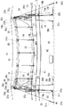
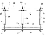
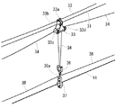
図1は本発明の第1の実施の形態に係る移線工法を示し、図2は図1の複数の金車で電線を吊下げた状態を示し、さらに、図3は図2の続きを示す。また、図4は図2の金車による電線の吊下げ部分を斜視図で示す。
Hereinafter, the best mode for carrying out the present invention will be described with reference to the drawings.
(First Embodiment)
FIG. 1 shows a wire transfer method according to a first embodiment of the present invention, FIG. 2 shows a state in which electric wires are suspended by a plurality of metal wheels in FIG. 1, and FIG. 3 is a continuation of FIG. Show. FIG. 4 is a perspective view showing a suspended portion of the electric wire by the wheel of FIG.
図1において、移線元の既設の一対の鉄塔10a、10b(特許請求の範囲における「電線の支持物」に相当する。)間に三相の送電線11、12、13(特許請求の範囲における「架線用電線」に相当する。)が碍子10c、10dを介して架設されている。これらの送電線11、12、13を移線先の新設の一対の鉄塔16a、16b(特許請求の範囲における「電線の支持物」に相当する。)に移線する工法を以下のように述べる。なお、この場合、一対の鉄塔16a、16bの高さは一対の鉄塔10a、10bの高さより高いので、移線工程にて、送電線11、12、13は上方に吊上げられる必要がある。
In FIG. 1, three-
まず、鉄塔16aの上部に、滑車25a、25b、25c、25dを取り付け、鉄塔16aの下部に滑車25e、25f、25gを取り付け、鉄塔16bにも滑車25a〜25gに相当する滑車25i、25j、25k、25m、25n、25p、25qを取り付ける。
つぎに、鉄塔16a、16b間の既設の図示しない電線(例えば架空地線17)を利用し、主索31を連結した自走機をこの電線に沿って走らせる方法等により、鉄塔16aの滑車25aおよび鉄塔16bの滑車25iに主索31を掛け渡し、主索31の図示左側端部をターンバックル31cを介してアンカー31aにより鉄塔16aの近傍の地面41に固定し、同様に主索31の図示右側端部をアンカー31bにより鉄塔16bの近傍の地面41に固定する。ここで、ターンバックル31cにより主索31の弛みを調節することができる。さらに、ターンバックル31cにロードセル式張力計を付設して、これにより主索31に加わる張力を測定してこの張力が適正値になるように管理することができる。
First,
Next, a pulley of the
つぎに、図1の二点鎖線で示すように、鉄塔16a側において、主索31に所定数の吊金車33を吊下げる。ここで、図4に示すように、吊金車33は主索31に掛ける滑車33bおよび滑車33bの下側に平行に配置された2つの滑車33c、33dを備えている。このため、吊金車33は滑車33bにより主索31に沿って移動することができる。そして、吊金車33の上端部を固定クリップ33aにより曳行ロープ32に所定間隔で固定する。
その後、巻上げロープ34(特許請求の範囲における「ロープ」に相当する。)を吊金車33の滑車33c、金車36、前記滑車33cを備える吊金車33の滑車33dに順次掛けることを繰り返し、各吊金車33ごとに金車36を吊下げる(図4参照)。
Next, as shown by a two-dot chain line in FIG. 1, a predetermined number of hanging
Thereafter, the hoisting rope 34 (corresponding to the “rope” in the claims) is repeatedly wound around the
つぎに、各金車36に金車37を吊下げる。なお、予め金車37が吊下げられた金車36を使用してもよい。ここで、金車36、37は特許請求の範囲における「電線保持手段」に相当する。各金車36の下端を固定クリップ36aにより連結ロープ38に固定する。さらに、各金車37により送電線11を保持する。すなわち、各金車37のフレームの一部分を開閉して送電線11を各金車37のローラに掛けることができる。この状態の吊金車33、金車36、37等を二点鎖線で図1に示す。
Next, the
そして、前記自走機に曳行ローブ32の端部、巻上げロープ34の端部および連結ロープ38の端部を連結し、前記自走機を鉄塔16a側から鉄塔16b側まで架空地線17に沿って走行させることにより、図1に示すように、これらの吊金車33を曳行ロープ32で曳いて、所定の適正な間隔で主索31に吊下げ、曳行ロープ32の両端部をそれぞれ鉄塔16a、16bに結びつけると、主索31上の吊金車33の位置が固定される。なお、鉄塔16a、16bの頂部には架空地線17が架設されているので、曳行ロープ32は、架空地線17の下側に配置される。
Then, the end of the towing
つぎに、巻上げロープ34の図示左端部を鉄塔16aに取り付けられた滑車25d、25eを介して地上に設置したウインチ35aで牽引可能にし、巻上げロープ34の図示右端部(前記自走機で引っ張った端部)を鉄塔16bに取り付けられた滑車25m、25nを介して地上に設置したウインチ35bで牽引可能にする。
連結ロープ38の鉄塔16a側端部および鉄塔16b側端部(前記自走機で引っ張った端部)をそれぞれ鉄塔16a、16bの上部に結び付けると、各金車36、37の横方向の間隔を所定の適正な間隔に保つことができ、各金車36、37を安定させることができる。この状態で、各金車37が移線用の送電線11の各部分を保持している。
Next, the illustrated left end of the hoisting
When the end of the connecting
また、鉄塔16aに、移線用の吊上げ装置21を取り付ける。吊上げ装置21は、図6に示すように、H形のフレーム21aに上側の一対の滑車21b、21cおよび下側の一対の滑車21d、21eを取り付けたものである。その際、図5に示すように、滑車25b、25cを使用して吊上げ装置21を鉄塔16aに吊下げ、吊上げ装置21を吊上げる巻上げワイヤ21x、21yを滑車25f、25gを介して地面41に設置したウインチ23で牽引可能にする。
In addition, a
図1に示すように、鉄塔16b側においても、鉄塔16a側と同様に、滑車25j、25kを使用して吊上げ装置22を鉄塔16bに吊下げ、吊上げ装置22を吊上げる巻上げワイヤ(前記図5の巻上げワイヤ21x、21yに相当する)を滑車25p、25qを介して地面41に設置したウインチ24で牽引可能にする。
As shown in FIG. 1, also on the
つぎに、吊上げ装置21、22により送電線11を保持する。その際、図6に示すように吊上げ装置21の滑車21d、21eのローラに送電線11を掛けることにより、送電線11を保持するようにする。同様にして、図1に示すように、吊上げ装置22により送電線11を保持する。その際、各滑車(21d等)のフレームの一部分を開閉して送電線11を各滑車(21d等)に掛けることができる。
Next, the
つぎに、送電線11を鉄塔10a、10bから外した後、ウインチ35a、35bにより巻上げロープ34を牽引することにより、図2および図3に示すように、金車37により送電線11の各部分をバランスを保って吊上げる。このように、金車37が移線用の送電線11の各部分を保持し、この金車37を吊り下げる巻上げロープ34を牽引して金車37の上下方向の位置を調節するので、送電線11をその弛みを少なくしつつバランスよく安全に移線することができる。
同時に、図1に示すウインチ23、24により吊上げ装置21、22を吊上げて、吊上げ装置21、22によっても送電線11を吊上げる。
このようにして、送電線11を図1の鉄塔16a、16bの架線位置までバランスを保ちつつ移動させる。つぎに、送電線11を鉄塔16a、16bに碍子16c、16dを介して架線する。その後、送電線11を各金車37および吊上げ装置21、22から取り外す。
Next, after removing the
At the same time, the
In this way, the
つぎに、図1に示す送電線12を鉄塔10a、10bから鉄塔16a、16bに移線する。送電線12は送電線11の下側に架設されているので、移線ずみの送電線11を主索31の代わりに使用する。このようにすると、送電線12の移線を円滑に行うことができる。
さらに、図1に示す送電線13を鉄塔10a、10bから鉄塔16a、16bに移線する。送電線13は送電線12の下側に架設されているので、移線ずみの送電線12を主索31の代わりに使用する。このようにすると、送電線13の移線を円滑に行うことができる。
このようにして、三相の送電線11、12、13を鉄塔10a、10bから鉄塔16a、16bに順次移線することができる。
Next, the
Further, the
In this manner, the three-
最後に、主索31、曳行ロープ32、吊金車33、金車36、37、吊上げ装置21、22等の移線工事用資材を撤去して移線工事を終了する。
Lastly, the materials for the transfer work such as the
以上の移線工程により、全ての吊金車33に1本の巻上げロープ34が掛けられ、この巻上げロープ34をウインチ35a、35bで牽引して各金車37に保持された送電線11、12、13を移線するようになっているので、移線中の送電線11、12、13の弛みを少なくし、かつ、移線中に急激な送電線11、12、13の垂下の状況は発生しないで、径間全体の送電線11、12、13を円滑に移線することができる。このため、地面41上の重要横断箇所42等から確実に離れた状態で送電線11、12、13を移線することができる。
By the above-described transfer process, one hoisting
なお、図5に示すように、滑車25bを介して吊上げ装置21の滑車21bを巻上げワイヤ21xで吊上げ、巻上げワイヤ21xの端部を滑車25fを介して地面41に設置したウインチ23で牽引可能にする。同様に、滑車25cを介して吊上げ装置21の滑車21cを巻上げワイヤ21yで吊上げ、巻上げワイヤ21yの端部を滑車25gを介してウインチ23で牽引可能にする。このため、巻上げワイヤ21x、21yはウインチ23により同時に牽引される。このように、2本の巻上げワイヤ21x、21yを併用することにより、例えそのうちの1本が切断する事故が発生しても安全性が保たれる。
As shown in FIG. 5, the
なお、上記実施の形態において、吊上げ装置21、22は必須のものではないので、これを省くこともできる。
また、主索31、巻上げロープ34、曳行ロープ32、連結ロープ38等にケブラー(登録商標)ロープを使用すると、主索31、巻上げロープ34、曳行ロープ32、連結ロープ38等の強度を向上させることができる。
In the above embodiment, since the
When Kevlar (registered trademark) rope is used for the
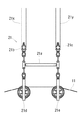
(第2の実施の形態)
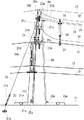
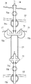
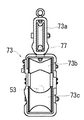
図7は本発明の第2の実施の形態に係る架線工法を示し、図8は図7の吊金車等を拡大して示し、図9は図8の上側の吊金車の右側面を示し、図10は図8の下側の吊金車の右側面を示す。
(Second embodiment)
7 shows an overhead wire construction method according to a second embodiment of the present invention, FIG. 8 shows an enlarged view of the suspension wheel of FIG. 7, and FIG. 9 shows the right side of the upper suspension wheel of FIG. FIG. 10 shows the right side of the lower suspension wheel in FIG.
図7の鉄塔50と鉄塔50の右側にある図示しない鉄塔との間に架設された三相の送電線51、52、53を張替える架線工法は、以下のようになる。
まず、鉄塔50に滑車54、55、56、57、58を取り付け、鉄塔50の図示左側の地面41上にコンクリートアンカー61および延線車62を配置し、鉄塔50の図示右側の地面41上にウインチ63を配置する。つぎに、最上段の送電線51を鉄塔50の図示しない碍子から外し、ワイヤを継ぎ足して滑車54を経てコンクリートアンカー61に連結する。そして、第2段の送電線52を鉄塔50の図示しない碍子から外し、ワイヤを継ぎ足して滑車55を経てコンクリートアンカー61に張力計65(送電線52の張力を図ることができる。)を介して連結する。さらに、第3段(最下段)の送電線51を鉄塔50の図示しない碍子から外し、ワイヤを継ぎ足して延線車62のドラムに巻き取る。上記図示しない鉄塔側においても同様に送電線51、52、53を処置する。但し、送電線53の線尻(前記図示しない鉄塔側の端部)は延線車が送り出す新しい送電線(送電線53の代わりとなるもの)に繋がれる。
The overhead wire construction method for replacing the three-phase
First, pulleys 54, 55, 56, 57, 58 are attached to the
つぎに、吊金車71を最上段にして吊下げロープ74により吊金車72の上端部を吊金車71の下端部に吊下げ、さらに、巻上げロープ77により吊金車73を吊金車72に吊下げる。ここで、吊金車72、巻上げロープ77および吊金車73は、それぞれ第1の実施の形態における「吊金車33」、「巻上げロープ34」および「金車36、37」に相当する。そして、吊金車71は上側の滑車71aおよび下側の滑車71bを備えているので、この滑車71a、71bの間に送電線51を挿通させる。
また、図8および図9に示すように、吊金車72は、上から順に滑車72a、72bおよび横方向に並んだ一対の滑車72c、72dを備え、図8および図10に示すように、吊金車73は上から順に滑車73a、滑車73bおよび滑車73cを備えている。このため、吊金車72の滑車72a、72bの間に送電線52を挿通し、滑車72c、72dにかけた巻上げロープ77で吊金車73の滑車73aを吊下げ、吊金車73の滑車73b、73c間に送電線53を挿通させる。なお、滑車72c、72dは巻上げロープ77に適合するように第1の実施例の滑車33c、33d(図4参照)よりも薄く形成され、軽量化が図られている。また、滑車73aも滑車72c、72dと同様に形成されている。
Next, the upper end of the
As shown in FIGS. 8 and 9, the hanging
上述のように吊金車71、72、73および巻上げロープ77を組み合わせたものを一組として、複数の組を構成し、各組の吊金車71を連結ロープ75により所定間隔で連結し、各組の吊金車72を連結ロープ76により所定間隔で連結する。そして、上記第1の実施の形態と同様にして、前記複数の組を送電線51に所定間隔で吊り下げる。巻上げロープ77は前記「巻上げロープ34」と同様にウインチ63で引っ張られる構成にされ、巻上げロープ77の図示左端部は滑車57、58を経て張力計66を介してウインチ63にて牽引可能になっている。また、連結ロープ75、76は第1の実施の形態の連結ロープ38と同様に鉄塔50と鉄塔50の右側にある図示しない鉄塔との間に連結されている。
As described above, a plurality of sets are formed by combining the hanging
つぎに、図7に示すように、張力計66で巻上げロープ77の張力を監視しつつ、ウインチ63により巻上げロープ77を牽引すると、吊金車73が吊金車72により吊上げられるので、吊金車73に支えられた送電線53が上方に吊上げられる。この状態で、送電線53を延線車62で巻き取ると、送電線53は新しい送電線に置き換えられる。このため、送電線53および前記新しい送電線は、弛みがあっても、その下側にある樹木81、建物82等に接触することを防ぐことができる。このため、送電線53を張替える工事を安全に行うことができる。その後、ウインチ63により巻き上げロープ77を前記牽引前に戻すと、吊金車73は元の位置に下がるので、送電線53に代わる新しい送電線は、その位置が所定の高さになり、この状態で、鉄塔50と鉄塔50の右側にある図示しない鉄塔との間に架線される。
Next, as shown in FIG. 7, when the hoisting
つぎに、送電線51、52の張替えを行う。この場合においても、送電線53と同様の巻き上げ方式吊金工法を使用することができる。
Next, the
また、吊下げロープ74は通常のロープであるが、これに限らず、伸縮ロープとしてもよい、このようにすると、図7において、送電線53の荷重を送電線52で支えることができる。
また、連結ロープ75、76および巻上げロープ77にケブラー(登録商標)ロープを使用すると、これらの強度を向上させることができる。
また、張力計65、66はなくてもよい。
また、上記第2の実施の形態は、電線の張替え延線工事であるが、これに限らず、本発明の電線の架線工法は、電線の新設延線および電線の撤去延線等の全ての延線に適用できる。ここで、電線の新設延線の場合には、前記「送電線51、52、53」の各々の代わりにワイヤ等とし、このワイヤ等の線尻(前記図示しない鉄塔側端部)に新しい送電線を繋ぎ、このワイヤ等を新しい送電線に置き換えることになる。また、電線の撤去延線の場合には、新しい送電線の代わりにワイヤ等を前記「送電線51、52、53」の線尻に繋ぎ、前記「送電線51、52、53」を前記ワイヤ等に置き換える。
Further, the hanging
When Kevlar (registered trademark) rope is used for the connecting
Further, the
In the second embodiment, the wire replacement and extension work is performed. However, the present invention is not limited to this. Applicable to extension wire. Here, in the case of a new extension of an electric wire, a wire or the like is used instead of each of the above-mentioned "
本発明は、鉄塔等に電線を架線する送電線工事において有用である。 INDUSTRIAL APPLICABILITY The present invention is useful in transmission line construction for wiring an electric wire to a steel tower or the like.
10a、10b 移線元の鉄塔(電線の支持物)
11、12、13 送電線(架線用電線)
16a、16b 移線先の鉄塔(電線の支持物)
31 主索
32 曳行ロープ
33 吊金車
33c、33d 滑車
34 巻上げロープ(ロープ)
35a、35b ウインチ
36、37 金車(電線保持手段)
50 鉄塔(電線の支持物)
51、52、53 送電線
63 ウインチ
71 吊金車
72 吊金車
72c、72d 滑車
73 吊金車(電線保持手段)
77 巻上げロープ(ロープ)
10a, 10b Transfer tower (support for electric wires)
11, 12, 13 Transmission line (wire for overhead line)
16a, 16b Transfer tower (wire support)
31
35a,
50 steel tower (support for electric wires)
51, 52, 53
77 Hoisting rope (rope)
Claims (4)
つぎに、前記主索に所定間隔で吊下げた所定数の吊金車の各々に掛けたロープで各吊金車ごとに電線保持手段を吊下げ、このロープの少なくとも一方の端部を牽引可能にし、前記各電線保持手段に、架線用電線の各部分を保持させ、
そして、前記ロープの牽引状態を調節して、前記電線保持手段の上下方向の位置を調節することを特徴とする電線の架線工法。 The main rope is hung between the supports of the electric wire at the overhead line,
Next, the wire holding means is hung on each of the hanging wheels by a rope hung on each of a predetermined number of hanging wheels suspended at predetermined intervals on the main rope, and at least one end of the rope can be pulled. In each of the wire holding means, to hold each part of the overhead wire,
And adjusting the pulling state of the rope to adjust the vertical position of the electric wire holding means.
前記各吊金車が2つの滑車を有する吊金車であり、
前記各吊金車の2つの滑車に掛けたロープの前記各2つの滑車間の部分で電線保持手段を吊下げ、このロープの少なくとも一方の端部を牽引可能にし、
前記ロープの少なくとも一方の端部の牽引状態を調節して前記電線保持手段の上下方向の位置を調節することを特徴とする電線の架線工法。 An overhead wire construction method according to claim 1,
Each of the pulleys is a pulley having two pulleys;
Suspending the wire holding means at a portion between the two pulleys of the rope hanging on the two pulleys of each of the pulleys, allowing at least one end of the rope to be towed,
A method of wire-laying an electric wire, wherein a vertical position of the electric wire holding means is adjusted by adjusting a pulling state of at least one end of the rope.
前記主索が架線先に架線済みの電線であることを特徴とする電線の架線工法。 An overhead wire construction method according to claim 1 or 2,
A method of wiring an electric wire, wherein the main rope is an electric wire that has been connected to an overhead wire.
前記ロープの端部を地面に設置したウインチで牽引することを特徴とする電線の架線工法。
An overhead wire construction method for an electric wire according to claim 1, 2, or 3,
A method of wiring an electric wire, wherein the end of the rope is pulled by a winch installed on the ground.
Priority Applications (1)
| Application Number | Priority Date | Filing Date | Title |
|---|---|---|---|
| JP2003300195A JP3929951B2 (en) | 2003-02-24 | 2003-08-25 | Electric wire overhead method |
Applications Claiming Priority (2)
| Application Number | Priority Date | Filing Date | Title |
|---|---|---|---|
| JP2003046471 | 2003-02-24 | ||
| JP2003300195A JP3929951B2 (en) | 2003-02-24 | 2003-08-25 | Electric wire overhead method |
Publications (2)
| Publication Number | Publication Date |
|---|---|
| JP2004282984A true JP2004282984A (en) | 2004-10-07 |
| JP3929951B2 JP3929951B2 (en) | 2007-06-13 |
Family
ID=33301693
Family Applications (1)
| Application Number | Title | Priority Date | Filing Date |
|---|---|---|---|
| JP2003300195A Expired - Lifetime JP3929951B2 (en) | 2003-02-24 | 2003-08-25 | Electric wire overhead method |
Country Status (1)
| Country | Link |
|---|---|
| JP (1) | JP3929951B2 (en) |
Cited By (10)
| Publication number | Priority date | Publication date | Assignee | Title |
|---|---|---|---|---|
| JP2009060770A (en) * | 2007-09-04 | 2009-03-19 | Tlc:Kk | Electric wire replacement method |
| JP2010142005A (en) * | 2008-12-10 | 2010-06-24 | Tlc:Kk | Method for moving electric cable in vertical direction |
| KR101066637B1 (en) | 2011-05-20 | 2011-09-21 | 티앤제이건설 주식회사 | Deflection prevention device of overhead transmission line |
| CN102208777A (en) * | 2011-03-24 | 2011-10-05 | 青海送变电工程公司 | Construction method for parallel suspension of lead trolleys by using V-shaped strings |
| KR101206886B1 (en) | 2011-08-22 | 2012-11-30 | 박귀현 | Suspension for communication cable |
| CN103500963A (en) * | 2013-09-24 | 2014-01-08 | 国网上海市电力公司 | Suspension device for wire-unwinding tackle with combination between one-pull-four mode and one-pull-two mode |
| CN103825214A (en) * | 2013-10-12 | 2014-05-28 | 国家电网公司 | Novel guide rope laying one-pull-seven construction method |
| CN106229890A (en) * | 2016-07-28 | 2016-12-14 | 郑州东辰科技有限公司 | Across obstacle Poling Construction protection structure |
| CN108899803A (en) * | 2018-08-31 | 2018-11-27 | 国网江苏省电力有限公司淮安供电分公司 | A kind of electrification aerial cable moving trolley |
| KR20210156614A (en) * | 2020-06-18 | 2021-12-27 | 한국전력공사 | Transmission line cabling system and transmission line cabling method |
Families Citing this family (1)
| Publication number | Priority date | Publication date | Assignee | Title |
|---|---|---|---|---|
| KR102569829B1 (en) * | 2021-06-16 | 2023-08-24 | 한국전력공사 | Pulley assembly for replacing transmission line |
-
2003
- 2003-08-25 JP JP2003300195A patent/JP3929951B2/en not_active Expired - Lifetime
Cited By (13)
| Publication number | Priority date | Publication date | Assignee | Title |
|---|---|---|---|---|
| JP2009060770A (en) * | 2007-09-04 | 2009-03-19 | Tlc:Kk | Electric wire replacement method |
| JP2010142005A (en) * | 2008-12-10 | 2010-06-24 | Tlc:Kk | Method for moving electric cable in vertical direction |
| CN102208777A (en) * | 2011-03-24 | 2011-10-05 | 青海送变电工程公司 | Construction method for parallel suspension of lead trolleys by using V-shaped strings |
| KR101066637B1 (en) | 2011-05-20 | 2011-09-21 | 티앤제이건설 주식회사 | Deflection prevention device of overhead transmission line |
| KR101206886B1 (en) | 2011-08-22 | 2012-11-30 | 박귀현 | Suspension for communication cable |
| CN103500963A (en) * | 2013-09-24 | 2014-01-08 | 国网上海市电力公司 | Suspension device for wire-unwinding tackle with combination between one-pull-four mode and one-pull-two mode |
| CN103825214A (en) * | 2013-10-12 | 2014-05-28 | 国家电网公司 | Novel guide rope laying one-pull-seven construction method |
| CN106229890A (en) * | 2016-07-28 | 2016-12-14 | 郑州东辰科技有限公司 | Across obstacle Poling Construction protection structure |
| CN106229890B (en) * | 2016-07-28 | 2024-04-12 | 郑州东辰科技有限公司 | Construction protection structure for crossing obstacle overhead line |
| CN108899803A (en) * | 2018-08-31 | 2018-11-27 | 国网江苏省电力有限公司淮安供电分公司 | A kind of electrification aerial cable moving trolley |
| CN108899803B (en) * | 2018-08-31 | 2023-09-29 | 国网江苏省电力有限公司淮安供电分公司 | A kind of electrified overhead cable traveling vehicle |
| KR20210156614A (en) * | 2020-06-18 | 2021-12-27 | 한국전력공사 | Transmission line cabling system and transmission line cabling method |
| KR102446767B1 (en) * | 2020-06-18 | 2022-09-26 | 한국전력공사 | Transmission line wiring system and transmission line wiring method |
Also Published As
| Publication number | Publication date |
|---|---|
| JP3929951B2 (en) | 2007-06-13 |
Similar Documents
| Publication | Publication Date | Title |
|---|---|---|
| JP5572668B2 (en) | Replacement method of oblique cable and temporary hanger for replacing oblique cable | |
| JP2004282984A (en) | Electric cable laying method | |
| CN108462117B (en) | High-rise building cable laying device and application method thereof | |
| JP5812325B2 (en) | Electric wire tension reduction device and electric wire tension reduction method | |
| JP5065814B2 (en) | Electric wire replacement method | |
| KR101952156B1 (en) | Wire system for replacing sloped cable and method for replacing sloped cable | |
| CN119121814B (en) | A method for dismantling long-span steel strand cable stays | |
| JP4491110B2 (en) | Elevator rope hanging method | |
| JP3277486B2 (en) | Existing main rope winding device of the elevator | |
| JP5280175B2 (en) | Electric wire vertical transfer method | |
| JP7407981B1 (en) | Elevator equipment and its installation method | |
| CN111478228B (en) | Butt joint method of multi-split large-section lead and strain insulator string | |
| KR101103134B1 (en) | Rigging Device | |
| JP4041108B2 (en) | Aerial cable laying method and cable lifting jig | |
| JP4956286B2 (en) | Winding drum wire winding method at crane installation | |
| CN103224180B (en) | The main cable replacing options of elevator | |
| KR101327759B1 (en) | Pulling up apparatus for installing cable of suspension bridge and installing condition thereof | |
| CN207896560U (en) | A kind of skyscraper cable-laying gear | |
| CN108840266A (en) | Cylindrical apparatus rolls the method and device of translation | |
| CN217087315U (en) | Device for replacing existing groove type bridge | |
| JP3401752B2 (en) | Overhead wire work method for suspended supports | |
| RU2546356C2 (en) | Method and device for electric rope pulley demounting | |
| JP2001226082A (en) | Cable winding device | |
| JP5334026B2 (en) | How to hang an elevator rope | |
| JPH1072184A (en) | Cable crane |
Legal Events
| Date | Code | Title | Description |
|---|---|---|---|
| A977 | Report on retrieval |
Free format text: JAPANESE INTERMEDIATE CODE: A971007 Effective date: 20060418 |
|
| A131 | Notification of reasons for refusal |
Free format text: JAPANESE INTERMEDIATE CODE: A131 Effective date: 20060523 |
|
| A521 | Request for written amendment filed |
Free format text: JAPANESE INTERMEDIATE CODE: A523 Effective date: 20060721 |
|
| TRDD | Decision of grant or rejection written | ||
| A01 | Written decision to grant a patent or to grant a registration (utility model) |
Free format text: JAPANESE INTERMEDIATE CODE: A01 Effective date: 20070206 |
|
| A61 | First payment of annual fees (during grant procedure) |
Free format text: JAPANESE INTERMEDIATE CODE: A61 Effective date: 20070307 |
|
| R150 | Certificate of patent or registration of utility model |
Ref document number: 3929951 Country of ref document: JP Free format text: JAPANESE INTERMEDIATE CODE: R150 Free format text: JAPANESE INTERMEDIATE CODE: R150 |
|
| FPAY | Renewal fee payment (event date is renewal date of database) |
Free format text: PAYMENT UNTIL: 20100316 Year of fee payment: 3 |
|
| S531 | Written request for registration of change of domicile |
Free format text: JAPANESE INTERMEDIATE CODE: R313531 |
|
| FPAY | Renewal fee payment (event date is renewal date of database) |
Free format text: PAYMENT UNTIL: 20100316 Year of fee payment: 3 |
|
| R350 | Written notification of registration of transfer |
Free format text: JAPANESE INTERMEDIATE CODE: R350 |
|
| FPAY | Renewal fee payment (event date is renewal date of database) |
Free format text: PAYMENT UNTIL: 20100316 Year of fee payment: 3 |
|
| FPAY | Renewal fee payment (event date is renewal date of database) |
Free format text: PAYMENT UNTIL: 20130316 Year of fee payment: 6 |
|
| R250 | Receipt of annual fees |
Free format text: JAPANESE INTERMEDIATE CODE: R250 |
|
| FPAY | Renewal fee payment (event date is renewal date of database) |
Free format text: PAYMENT UNTIL: 20160316 Year of fee payment: 9 |
|
| R250 | Receipt of annual fees |
Free format text: JAPANESE INTERMEDIATE CODE: R250 |
|
| R250 | Receipt of annual fees |
Free format text: JAPANESE INTERMEDIATE CODE: R250 |
|
| R250 | Receipt of annual fees |
Free format text: JAPANESE INTERMEDIATE CODE: R250 |
|
| S533 | Written request for registration of change of name |
Free format text: JAPANESE INTERMEDIATE CODE: R313533 |
|
| R350 | Written notification of registration of transfer |
Free format text: JAPANESE INTERMEDIATE CODE: R350 |
|
| R250 | Receipt of annual fees |
Free format text: JAPANESE INTERMEDIATE CODE: R250 |
|
| EXPY | Cancellation because of completion of term |