JP2004276127A - Die machining program creation method and device, record medium storing the program and wire cut electric discharge machine - Google Patents
Die machining program creation method and device, record medium storing the program and wire cut electric discharge machine Download PDFInfo
- Publication number
- JP2004276127A JP2004276127A JP2003066916A JP2003066916A JP2004276127A JP 2004276127 A JP2004276127 A JP 2004276127A JP 2003066916 A JP2003066916 A JP 2003066916A JP 2003066916 A JP2003066916 A JP 2003066916A JP 2004276127 A JP2004276127 A JP 2004276127A
- Authority
- JP
- Japan
- Prior art keywords
- machining
- program
- cutting position
- die
- processing
- Prior art date
- Legal status (The legal status is an assumption and is not a legal conclusion. Google has not performed a legal analysis and makes no representation as to the accuracy of the status listed.)
- Granted
Links
Images


Classifications
-
- G—PHYSICS
- G05—CONTROLLING; REGULATING
- G05B—CONTROL OR REGULATING SYSTEMS IN GENERAL; FUNCTIONAL ELEMENTS OF SUCH SYSTEMS; MONITORING OR TESTING ARRANGEMENTS FOR SUCH SYSTEMS OR ELEMENTS
- G05B19/00—Programme-control systems
- G05B19/02—Programme-control systems electric
- G05B19/18—Numerical control [NC], i.e. automatically operating machines, in particular machine tools, e.g. in a manufacturing environment, so as to execute positioning, movement or co-ordinated operations by means of programme data in numerical form
- G05B19/4093—Numerical control [NC], i.e. automatically operating machines, in particular machine tools, e.g. in a manufacturing environment, so as to execute positioning, movement or co-ordinated operations by means of programme data in numerical form characterised by part programming, e.g. entry of geometrical information as taken from a technical drawing, combining this with machining and material information to obtain control information, named part programme, for the NC machine
-
- B—PERFORMING OPERATIONS; TRANSPORTING
- B23—MACHINE TOOLS; METAL-WORKING NOT OTHERWISE PROVIDED FOR
- B23H—WORKING OF METAL BY THE ACTION OF A HIGH CONCENTRATION OF ELECTRIC CURRENT ON A WORKPIECE USING AN ELECTRODE WHICH TAKES THE PLACE OF A TOOL; SUCH WORKING COMBINED WITH OTHER FORMS OF WORKING OF METAL
- B23H7/00—Processes or apparatus applicable to both electrical discharge machining and electrochemical machining
- B23H7/02—Wire-cutting
- B23H7/06—Control of the travel curve of the relative movement between electrode and workpiece
-
- B—PERFORMING OPERATIONS; TRANSPORTING
- B23—MACHINE TOOLS; METAL-WORKING NOT OTHERWISE PROVIDED FOR
- B23H—WORKING OF METAL BY THE ACTION OF A HIGH CONCENTRATION OF ELECTRIC CURRENT ON A WORKPIECE USING AN ELECTRODE WHICH TAKES THE PLACE OF A TOOL; SUCH WORKING COMBINED WITH OTHER FORMS OF WORKING OF METAL
- B23H2600/00—Machining conditions
- B23H2600/10—Switching of machining conditions during machining
- B23H2600/12—Switching from rough cutting to finish machining
-
- G—PHYSICS
- G05—CONTROLLING; REGULATING
- G05B—CONTROL OR REGULATING SYSTEMS IN GENERAL; FUNCTIONAL ELEMENTS OF SUCH SYSTEMS; MONITORING OR TESTING ARRANGEMENTS FOR SUCH SYSTEMS OR ELEMENTS
- G05B2219/00—Program-control systems
- G05B2219/30—Nc systems
- G05B2219/49—Nc machine tool, till multiple
- G05B2219/49324—Different starting point for each machining pass, to prevent dent formation
-
- Y—GENERAL TAGGING OF NEW TECHNOLOGICAL DEVELOPMENTS; GENERAL TAGGING OF CROSS-SECTIONAL TECHNOLOGIES SPANNING OVER SEVERAL SECTIONS OF THE IPC; TECHNICAL SUBJECTS COVERED BY FORMER USPC CROSS-REFERENCE ART COLLECTIONS [XRACs] AND DIGESTS
- Y02—TECHNOLOGIES OR APPLICATIONS FOR MITIGATION OR ADAPTATION AGAINST CLIMATE CHANGE
- Y02P—CLIMATE CHANGE MITIGATION TECHNOLOGIES IN THE PRODUCTION OR PROCESSING OF GOODS
- Y02P90/00—Enabling technologies with a potential contribution to greenhouse gas [GHG] emissions mitigation
- Y02P90/02—Total factory control, e.g. smart factories, flexible manufacturing systems [FMS] or integrated manufacturing systems [IMS]
Landscapes
- Engineering & Computer Science (AREA)
- Physics & Mathematics (AREA)
- Automation & Control Theory (AREA)
- Human Computer Interaction (AREA)
- Manufacturing & Machinery (AREA)
- General Physics & Mathematics (AREA)
- Geometry (AREA)
- Chemical & Material Sciences (AREA)
- Chemical Kinetics & Catalysis (AREA)
- Electrochemistry (AREA)
- Mechanical Engineering (AREA)
- Electrical Discharge Machining, Electrochemical Machining, And Combined Machining (AREA)
- Numerical Control (AREA)
- Extrusion Of Metal (AREA)
Abstract
Description
【0001】
【発明の属する技術分野】
本発明は、ワイヤ放電加工によるダイ加工用のプログラムの作成方法、作成装置及び該プログラムを記録した記録媒体並びに該プログラム作成装置を備えるワイヤカット放電加工機に関する。
【0002】
【従来の技術】
ワイヤカット放電加工によって、ダイ加工を行う場合、荒加工から仕上加工まで、複数回の加工を行う。この場合、荒加工から仕上加工まで同様な経路を通って放電加工が行われ、毎回同じ切込み位置から加工が行われる。
【0003】
図6は、従来から行われているダイ加工の一例であり、この例では円の形状のダイ加工を行う例を記載している。図6(a)はワイヤ電極の加工経路を表す図で、図6(b)はこの加工を行うプログラムの例を示している。図6(a)で、符号1は加工形状の円であり、符号2,3,4の白抜きの矢印は、ワイヤ電極の加工経路を表し、この例では4回の加工の例を示している。又、座標系は、図6において右横方向が+X、上方向が+Yとしている。
【0004】
まず、ダイ1回目の加工としては、加工開始位置(この例では加工形状の円1の中心)Q(この例では加工開始位置をX=0,Y=0の位置としている)より、X軸+方向に「10」の位置の切込み位置P0へ移動させるがこのとき、進行方向に向かって右側に設定オフセット量を補正する指令「G01G42X10.」がプログラムされている。この指令により矢印2で示したようにワイヤ電極は加工開始位置Qから切込み位置P0まで、直線移動し放電加工する。次に時計方向周りの円弧補間で所定切り残し部を残した加工形状の円1に沿った所定位置(X,Y)が指令され(「G02X Y I−10.」)、矢印3に示すように加工形状円1に沿って放電加工して指令位置で加工を一時停止し(「M01」)、オペレータが機械操作盤の起動ボタンを操作することによって、切り落とし加工を行い(「X10.Y0I J 」)、この切り落とし加工(矢印4参照)後、停止(「M00」)し、切り落とされた中子を取り除き加工開始位置(円1の中心)Qに戻る。
【0005】
第2回目の加工としては、加工開始位置(円1の中心)Qから切込み位置までの切削送りでの直線移動が指令されるが、この2回目の加工では、進行方向に対して左にオフセットする指令(「G01G41X10.」)、それに続いて、加工円1に沿った反時計回りの円弧補間指令がプログラムされている。なお、円弧の中心位置を示す(I,J)の指令(IがX座標値、JがY座標値)で、図6(b)では、J=0が省略され「I=−10.」がプログラムされている。このプログラムにより、加工経路は、第1回目の加工とは逆方向に移動し加工形状1の全周の第1回目の仕上加工がなされることになる。
【0006】
第3回目の加工として、進行方向に向かって右側にオフセットして切込み位置P0までの直線補間指令(「G01G42X10.」)、それに続き、時計回りの円弧補間指令(「G02I−10.」)により加工形状1の円に沿って時計方向に第2回目の仕上加工がなされる。
【0007】
同様に、第4回目の加工(第3回目の仕上加工)が反時計方向周りに加工されるようプログラムされ、ワイヤ電極は加工形状円1に沿って矢印3に示すように反時計方向に移動して円1の仕上加工を行う。
以上のように従来のダイ加工では、加工開始位置Qから切込み位置P0へ移動し、交互に逆方向に移動することによって複数回の加工が実行されている。
【0008】
【発明が解決しようとする課題】
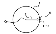
上述したように、従来の荒加工、仕上加工と複数回行われるダイ加工では、切込み位置が各回とも同一位置である。そのため、図7に示すように、加工の回数が進むにつれて、この切込み位置P0において、凹部形状の食い込み5が発生する傾向にある。
そこで、本発明の目的は、この食い込み発生を防止するダイ加工用のプログラムの作成方法、作成装置及び該プログラムを記録した記録媒体並びに該プログラム作成装置を備えるワイヤカット放電加工機を提供することにある。
【0009】
【課題を解決するための手段】
本願請求項1乃至4に係わる発明は、ワイヤカット放電加工に用いるダイ加工用プログラムの作成方法であって、ダイ加工を複数回実行するプログラムを各回数毎に切込み位置を変更することを特徴とするものである。又、コアレス加工後の仕上加工を複数回実行するプログラムにおいても、各回数毎に切込み位置を変更してプログラムを作成するダイ加工用プログラム作成方法である。又、切込み位置を変える1つの方法として、加工しようとする形状の1周を加工回数で等分した点を各回の加工の切込み位置とする。又、その切込み位置が加工しようとする形状のコーナから第1の所定距離以内のときには、該コーナから第2の所定距離だけ離れた点を切込み位置としてダイ加工用プログラムを作成するものである。
【0010】
請求項5乃至8に係わる発明は、ワイヤカット放電加工に用いるダイ加工用プログラムの作成装置であって、ダイ加工を複数回実行するプログラムを各回数毎に切込み位置を変更して作成する手段を備えたことを特徴とするものである。又、コアレス加工の場合には、コアレス加工後の仕上加工を複数回実行するプログラムを各回数毎に切込み位置を変更して作成する手段を備えるようにした。また、切込み位置を変更するために、入力された加工形状と加工回数により、加工形状を加工回数で等分した点を各回の加工の切込み位置として算出する切込み位置算出手段を備えるようにした。そして、この切込み位置算出手段は、前記切り込み位置が加工形状のコーナから第1の所定距離以内のときには、該コーナから第2の所定距離だけ離れた点を切込み位置として変更して算出するようにした。
【0011】
請求項9乃至12に係わる発明は、上述した請求項1〜8に係わるダイ加工用プログラム作成方法を実施するプログラムを記憶するコンピュータ読取可能な記録媒体である。又、請求項13に係わる発明は、請求項5乃至8に係わる発明のワイヤカット放電加工用のプログラム作成装置の実行する機能と同等の機能を備えたワイヤカット放電加工機である。
【0012】
【発明の実施の形態】
図1は本発明におけるダイ加工の加工方法及び加工プログラムの一実施形態を表す図である。この図1は、図6に示した従来の円形状のダイ加工と同一の加工形状1を、本発明を適用して加工する場合の例を示している。第1回目の加工は、図6に示した従来の加工と同一であり加工プログラムも同一である。
【0013】
しかし、第2回目の加工は、切込み位置P1が加工形状1の1周の1/4だけ時計方向周りに進んだ位置にされている。そして加工プログラムは、加工開始位置Qからオフセット補正した切込み位置P1へ、Y軸−方向に「10」移動させる指令「G01G41Y−10.」がプログラムされる。そして、1回目の加工方向とは逆方向(反時計方向)の加工形状1周の加工指令「G03J10.」がプログラムされている。なお切込み位置P1から加工形状1の円中心はI=0,J=10の位置であるから、I=0が省略されて「J10」の指令がなされている。
【0014】
第3回目の加工では、さらに1/4周だけ進んだ位置P2(加工形状1の円の中心からX軸方向に−10移動した位置)を切込み位置とした指令(「G01G42X−10.」)とされ、この3回目の加工は2回目とは逆方向で1回目と同一方向で順方向に移動する加工形状1を1周する加工指令(「G02I10.」)がプログラムされる。
【0015】
第4回目の加工は、さらに1/4周だけ進んだ位置P3(加工形状1の円の中心からY軸方向に+10移動した位置)が切込み位置として指令(「G01G41Y10.」)され、この4回目の加工は3回目とは逆方向(逆行加工)に加工形状1の1周の加工指令(「G02J−10.」)がプログラムされる。
【0016】
以上のようにして加工形状に対して荒加工、仕上加工を含めて複数回ワイヤカット放電加工が行われる際に各回の切込み位置Pが変わることにより、従来のように、切込み位置が同一であることによって生じていた食い込み(図7の符号5で示す凹部)が発生することはない。
【0017】
なお上述した実施形態では、加工形状の全周距離を加工回数で等分割し、その分割点を切込み位置Pとした。この場合、例えば図4(a)に示すような、矩形の折り曲がった加工形状のダイ加工の場合で、求めた切込み位置がコーナ位置の所定範囲内であるような場合には、該位置から所定量移動した図4(b)に示したような位置を切込み位置とする。又、求めた切り込み位置が所定の曲率以下の曲線区間から所定範囲内にある場合も同様に切り込み位置を移動する。
【0018】
又、加工形状の全周距離を加工回数で等分割した分割点を切込み位置Pとするのではなく、最初の切込み位置から所定量だけ加工形状に沿って毎回進めた位置を各回の切込み位置とするようにしてもよい。
又、上述したダイ加工を行うプログラムを、加工形状等を入力するだけで自動的に作成するようにしてもよい。
【0019】
図2は、本発明のダイ加工プログラムを作成する一実施形態のプログラム作成装置の要部ブロック図である。
プロセッサ(CPU)10には、ROM11,RAM12,グラフィック制御装置13,キーボード15,ハードディスクドライブ(HDD)16,フロッピー(登録商標)ディスクドライブ(FDD)17,CDドライブ(CDD)19がバス21で接続され、プロセッサ10は、ROM11に格納されたシステムプログラムに基づいて、このプログラム作成装置全体を制御する。RAM12は、データの一時記憶及び作成プログラムの記憶に利用される。
【0020】
グラフィック制御装置13はプロセッサ10からの表示データを表示信号に変換し、表示装置14に送る。表示装置14はこの表示信号を受けて画面表示を行う。この表示装置14には、CRT、液晶表示装置などが使用される。キーボード15はデータ入力や指令入力に使用される操作キーや、ファンクションキーなどを備える。ハードディスクドライブ(HDD)16は作成されたプログラムなど電源遮断後も保存すべきデータが格納される。又、フロッピー(登録商標)ディスクドライブ(FDD)17は、フロッピー(登録商標)ディスク18に記憶されたデータを読み込んだり、作成されたプログラムを該フロッピー(登録商標)ディスク18に書き込む。又、CDドライブ(CDD)19はCD−R又はCD−RW等のCD20に作成されたプログラムを書き込むものである。
【0021】
上述したプログラム作成装置のハードウエア構成は、従来から公知のプログラム作成装置と差異はない。
【0022】
本発明はこのようなプログラム作成装置を用いて、加工形状、加工開始位置、切込み位置、加工回数を入力するとダイ加工用プログラムを自動作成するシステムプログラムが格納されている。
図5は、このシステムプログラムに格納されているダイ加工用プログラム作成用プログラムによりプログラム作成装置がダイ加工用プログラムを作成する処理のフローチャートである。
【0023】
加工しようとする加工形状、加工開始位置Q、切込み位置P、加工回数n、さらには各回の加工におけるオフセット値を設定して、ダイ加工プログラム作成指令をキーボード15より入力すれば、プロセッサ10は図5に示す処理を実行する。
プロセッサ10は入力されている加工形状、加工開始位置Q、切込み位置P、加工回数n、オフセット値を読み取り(ステップ100)、入力加工形状から該加工形状1周の距離Lを算出する(ステップ101)。算出した1周の距離Lを加工回数nで割った分割量mを求める(ステップ102)。なお、mの値はL/nの値、その整数部のみ、小数点以下を四捨五入した値、切り上げた値等にしてもよい。
【0024】
次に、ステップ100で読み込んだ、加工開始位置Qから切込み位置Pまでの切削移動指令と該位置から、所定量の切り残しを残す位置までの加工経路に沿った時計回り方向の加工指令と、該位置での一時停止指令と、手動による切り落とし指令が入力されたときに移動する位置、すなわち切込み位置Pの位置指令と、停止指令の加工プログラムを作成しRAM12に格納する(ステップ103)。例えば、図1で示した加工形状1が円である場合、ステップ100で読み込んだデータより、
G01G42X10.
G02X Y I−10
M01
X10.Y0I J
M00
X0
のプログラムが作成されることになる。又、図3に示すような加工形状の加工である場合には、加工開始位置Qから切込み位置Pまでの移動指令、該位置から指令されている加工形状の各パスの加工移動指令、そして、最後に切り残し部を残し、一時停止する指令、切り落とし加工後停止する指令のプログラムが同様に作成されるものである。
【0025】
そして、次に、加工回数を計数するカウンタiを「1」にセットすると共に、加工方向を決める1ビットで構成されるレジスタRに「1」を設定する(ステップ104)。なお、このレジスタRに「0」がセットされていれば、最初の加工の方向と同一方向(オフセット方向も同一)でこの実施形態では時計回りの加工方向を指令し、「1」がセットされていれば最初の加工の方向と逆方向(この実施形態では反時計周りの加工方向)でオフセット方向も逆方向が指定されるものである。
【0026】
続いて、ステップ100で読み込んだ切込み位置Pにカウンタiの値にステップ102で求めた分割量mを乗じた値を加算し、当該加工回数目における切込み位置Pを求める(ステップ105)。この求めた位置Pが加工形状のコーナ位置から予め設定された第1の所定距離内であるか判断する(ステップ106)。すなわち、図4(a)に示すように加工形状のパスとパスの繋ぎ目でコーナ位置から予め設定された第1の所定距離内に求めた切り込み位置Pがある場合には、予め設定されている第2の所定距離ΔLだけ加算し、更新された切込み位置Pとする(ステップ107)。又、ステップ105で求めた切込み位置Pがコーナ位置の第1の所定距離内ではないときには該位置Pをそのまま切込み位置Pとする。
【0027】
次に、加工開始位置Qより求めた切込み位置PまでレジスタRに記憶する値によって決まるオフセット方向で直線補間の移動指令を作成し(ステップ108)、さらに、レジスタRに記憶する値に応じて時計回りか反時計回りかを決定し、加工形状を1周する移動指令を作成し格納する(ステップ109)。
【0028】
図1に示した例で2回目の加工の場合、i=1,R=1であることから、反時計回り方向で、ステップ100で読み取った切込み位置P0からi・m=1・(L/4)だけ時計回り方向に進んだ位置が切込み位置Pとなり加工開始位置Qから該位置Pまで直線補間の移動指令(ステップ108)と、該位置Pより加工形状を1周する加工経路を指令するプログラムが作成され、RAM12に格納した先の第1回目のプログラムに続けて格納される(ステップ109)。すなわち図1の例では、下記のプログラムが作成されRAM12に格納される。
G01G41Y−10.
G03J10.
Y0
次に、カウンタiに「1」加算し、レジスタRに「1」加算することによってその記憶値を反転させ(「1」を「0」に、「0」を「1」に反転させる)、カウンタiの値が加工回数n以上か判断する(ステップ110、111)。カウンタiの値が加工回数nに達していなければ、ステップ105に戻り、前述したステップ105以下の処理を行う。この場合、カウンタiが「1」加算されているから、この加算分に対応する分割量mだけ切込み位置Pが進められる。すなわち、図1の例では、カウンタiの値が「2」となると切込み位置P=P0+2・(L/4)となり1回目の加工時の切込み位置P0より1/2周分進んだ位置P2となる。又、レジスタRの値も反転され「0」となっているから、2回目とは逆方向のオフセット方向及び移動方向となり1回目と同一の方向(時計周り方向)の次のプログラムが作成されRAM12に格納される。
【0029】
G01G42X−10.
G02I10.
X0
そして、ステップ110でカウンタiに「1」加算され、レジスタRが反転されるから、i=3、R=1となるから、4回目の加工としては、切込み位置P=P0+3L/4となり、次のような加工方向は反時計回りの加工形状を1周するプログラムが作成されRAM12に格納されることになる。
【0030】
G01G41Y10.
G03J−10.
Y0
カウンタiに「1」加算されて(ステップ110)、該カウンタiの値が加工回数nに達すると、図1の例ではi=n=4に達すると、このダイ加工プログラム作成処理は終了する。
【0031】
こうして作成されたダイ加工用プログラムはRAM12からハードディスクドライブ16に転送されハードディスクに格納される。又、フロッピー(登録商標)ディスクドライブ(FDD)17,CDドライブ(CDD)19を介してフロッピー(登録商標)ディスク18、CD20に書き込まれる。
【0032】
なお、上述した実施形態では、加工形状の加工経路長を加工回数で等分割して各分割点を切込み位置としたが、予め設定した長さだけ加工経路に沿って加工回数毎に増加させるようにしてもよい。この場合ステップ102の処理は必要がなく、分割量mの代わりに、予め設定されたmの値がステップ105では使用されることになる。この場合、設定値mは加工回数をnとすると、
m・n<加工形状の全周距離L
となるようなmを設定するようにする。
【0033】
又、図5に示したダイ加工プログラムを作成するプログラムもフロッピー(登録商標)ディスク18やCD−R又はCD−RW等のCD20に格納し、このプログラムを従来のプログラム装置に読み込み、従来のプログラム装置でも上述したダイ加工用加工プログラムを、加工形状、加工開始位置、切込み位置、加工回数等を入力するだけで作成できるようにすることができる。
【0034】
さらに、上述したプログラム作成装置が有するプログラム作成機能をワイヤカット放電加工機の制御装置に組み込み、すなわち、ワイヤカット放電加工機の制御装置に上述したダイ加工用プログラム作成プログラムを格納し、ワイヤカット放電加工機自体が上述したダイ加工のプログラムを作成できるようにし、さらにはこの作成したプログラムを実行してダイ加工を行うようにすることもできる。
【0035】
又、上述した実施形態では、荒加工を行いその後仕上加工を行う例について説明したが、荒加工がコアレス加工でなされた場合では、複数回行われる仕上加工に対して本発明を適用し、上述した切込み位置を各仕上加工毎異なるようにして行うようにする。この例は、上述した例において、第1回目の加工が荒加工ではなく仕上加工となるものであり他は同一である。
【0036】
【発明の効果】
本発明による、ダイ加工のプログラムでは、荒加工、仕上加工を含めて加工が複数回実施される場合において、切込み位置での食い込みをなくし、加工精度のよいダイ加工をなすことができる。
【図面の簡単な説明】
【図1】本発明におけるダイ加工の加工方法及び加工プログラムの一実施形態を表す図である。
【図2】本発明のダイ加工プログラムを作成する一実施形態のプログラム作成装置の要部ブロック図である。
【図3】本発明のダイ加工プログラムを矩形の加工形状に適用したときの説明図である。
【図4】本発明のダイ加工プログラムを適用し、切込み位置がコーナ位置近傍のときに切込み位置を変更する説明図である。
【図5】本発明の一実施形態によるダイ加工プログラム作成処理のフローチャートである。
【図6】従来のダイ加工方法及び加工プログラムを表す説明図である。
【図7】従来のダイ加工により発生する切込み位置での食い込みを説明する図である。
【符号の説明】
1 ダイ加工の加工形状
2 加工開始位置から切込み位置までの移動経路
3 加工形状に沿った加工移動経路
5 食い込み[0001]
TECHNICAL FIELD OF THE INVENTION
The present invention relates to a method and a device for creating a program for die machining by wire electric discharge machining, a recording medium on which the program is recorded, and a wire cut electric discharge machine equipped with the program creating device.
[0002]
[Prior art]
When performing die machining by wire cut electric discharge machining, machining is performed a plurality of times from rough machining to finishing machining. In this case, electric discharge machining is performed through a similar path from rough machining to finish machining, and machining is performed from the same cutting position every time.
[0003]
FIG. 6 shows an example of a conventional die processing. In this example, a circular die processing is described. FIG. 6A shows a processing path of the wire electrode, and FIG. 6B shows an example of a program for performing this processing. In FIG. 6A,
[0004]
First, as the first processing of the die, the X axis is calculated from the processing start position (the center of the
[0005]
In the second machining, a linear movement in the cutting feed from the machining start position (center of the circle 1) Q to the cutting position is commanded, but in the second machining, an offset to the left with respect to the traveling direction is given. (“G01G41X10.”), And subsequently, a counterclockwise circular interpolation command along the
[0006]
As the third machining, a linear interpolation command (“G01G42X10.”) Offset to the right in the traveling direction to the cutting position P0, followed by a clockwise circular interpolation command (“G02I-10.”). A second finishing process is performed in a clockwise direction along the
[0007]
Similarly, the fourth processing (third finishing) is programmed to be processed in a counterclockwise direction, and the wire electrode moves counterclockwise along the
As described above, in the conventional die machining, the machining is performed a plurality of times by moving from the machining start position Q to the cutting position P0 and alternately moving in the opposite direction.
[0008]
[Problems to be solved by the invention]
As described above, in the conventional rough machining and finish machining, which are performed a plurality of times, the cutting position is the same position each time. For this reason, as shown in FIG. 7, as the number of times of processing increases, a concave portion-
Accordingly, it is an object of the present invention to provide a method for creating a die machining program for preventing the occurrence of bite, an apparatus for creating the program, a recording medium on which the program is recorded, and a wire cut electric discharge machine including the program creating apparatus. is there.
[0009]
[Means for Solving the Problems]
The invention according to
[0010]
The invention according to
[0011]
The invention according to claims 9 to 12 is a computer-readable recording medium for storing a program for executing the method for creating a die machining program according to
[0012]
BEST MODE FOR CARRYING OUT THE INVENTION
FIG. 1 is a diagram illustrating an embodiment of a processing method and a processing program for die processing according to the present invention. FIG. 1 shows an example of processing the
[0013]
However, in the second machining, the cutting position P1 is set at a position advanced clockwise by だ け of one round of the
[0014]
In the third machining, a command (“G01G42X-10.”) Is set as a cutting position at a position P2 (a position moved −10 in the X-axis direction from the center of the circle of the machining shape 1) further advanced by 周 turn. In the third machining, a machining command (“G02I10.”) For making one round of the
[0015]
In the fourth machining, a position P3 (a position moved +10 in the Y-axis direction from the center of the circle of the machining shape 1) further advanced by 1/4 turn is commanded as a cutting position (“G01G41Y10.”). In the third machining, a machining command (“G02J-10.”) For one round of the
[0016]
As described above, when the wire cut electric discharge machining is performed a plurality of times including the rough machining and the finishing machining on the machining shape, the cut position P is changed each time, so that the cut position is the same as in the related art. This does not cause the bite (recess indicated by
[0017]
In the above-described embodiment, the entire circumference of the processing shape is equally divided by the number of times of processing, and the division point is defined as the cutting position P. In this case, for example, in the case of die processing of a rectangular bent processing shape as shown in FIG. 4A, if the obtained cutting position is within a predetermined range of the corner position, the position is determined from the position. The position as shown in FIG. 4B, which has been moved by a predetermined amount, is defined as a cutting position. Also, when the calculated cutting position is within a predetermined range from a curved section having a predetermined curvature or less, the cutting position is similarly moved.
[0018]
Also, instead of using a division point obtained by equally dividing the entire circumferential distance of the processing shape by the number of processing times as the cutting position P, a position that has been advanced each time along the processing shape by a predetermined amount from the first cutting position is defined as a cutting position for each time. You may make it.
Further, a program for performing the above-described die machining may be automatically created simply by inputting a machining shape or the like.
[0019]
FIG. 2 is a block diagram of a main part of a program creating apparatus according to an embodiment for creating a die machining program according to the present invention.
ROM 11, RAM 12, graphic controller 13, keyboard 15, hard disk drive (HDD) 16, floppy (registered trademark) disk drive (FDD) 17, and CD drive (CDD) 19 are connected to processor (CPU) 10 via bus 21. The
[0020]
The graphic controller 13 converts display data from the
[0021]
The hardware configuration of the above-described program creation device is not different from a conventionally known program creation device.
[0022]
The present invention stores a system program for automatically creating a die machining program by inputting a machining shape, a machining start position, a cutting position, and the number of machining operations using such a program creating apparatus.
FIG. 5 is a flowchart of a process in which the program creating device creates a die machining program based on the die machining program creating program stored in the system program.
[0023]
If a processing shape to be processed, a processing start position Q, a cutting position P, a processing number n, and an offset value in each processing are set, and a die processing program creation command is input from the keyboard 15, the
The
[0024]
Next, a cutting movement command read from the machining start position Q to the cutting position P read in step 100 and a machining command in a clockwise direction along a machining path from the position to a position where a predetermined amount of uncut portion is left, A processing program of a temporary stop command at the position and a position to be moved when a manual cut-off command is input, that is, a position command of a cutting position P, and a stop command are created and stored in the RAM 12 (step 103). For example, if the
G01G42X10.
G02X Y I-10
M01
X10. Y0I J
M00
X0
Program will be created. In the case of machining with a machining shape as shown in FIG. 3, a movement command from the machining start position Q to the cutting position P, a machining movement command for each path of the machining shape commanded from the position, and Finally, a program for a command to temporarily stop the machine with the uncut portion left and a command to stop after the cut-off process is similarly created.
[0025]
Then, a counter i for counting the number of times of processing is set to "1", and "1" is set to a register R composed of 1 bit for determining a processing direction (step 104). If "0" is set in the register R, a clockwise machining direction is commanded in this embodiment in the same direction as the first machining direction (the same offset direction), and "1" is set. If so, the direction opposite to the direction of the first machining (in this embodiment, the counterclockwise machining direction) is also specified as the offset direction.
[0026]
Subsequently, a value obtained by multiplying the value of the counter i by the division amount m obtained in
[0027]
Next, a movement command for linear interpolation is created in the offset direction determined by the value stored in the register R up to the cutting position P obtained from the machining start position Q (step 108), and a clock is generated according to the value stored in the register R. It is determined whether the rotation is clockwise or counterclockwise, and a movement command for making one round of the machining shape is created and stored (step 109).
[0028]
In the case of the second processing in the example shown in FIG. 1, since i = 1 and R = 1, i · m = 1 · (L / m) in the counterclockwise direction from the cutting position P0 read in step 100. 4) A position advanced in the clockwise direction by only the incision position P becomes a cutting position P, and a movement command of linear interpolation from the processing start position Q to the position P (step 108) and a processing path for making one round of the processing shape from the position P A program is created and stored following the first program stored in the RAM 12 (step 109). That is, in the example of FIG. 1, the following program is created and stored in the RAM 12.
G01G41Y-10.
G03J10.
Y0
Next, “1” is added to the counter i, and the stored value is inverted by adding “1” to the register R (“1” is inverted to “0” and “0” is inverted to “1”), It is determined whether the value of the counter i is equal to or greater than the number of times of processing n (
[0029]
G01G42X-10.
G02I10.
X0
Then, at
[0030]
G01G41Y10.
G03J-10.
Y0
"1" is added to the counter i (step 110), and when the value of the counter i reaches the number of times of machining n, and in the example of FIG. 1, when i = n = 4, this die machining program creation processing ends. .
[0031]
The die machining program thus created is transferred from the RAM 12 to the
[0032]
In the above-described embodiment, the processing path length of the processing shape is equally divided by the number of times of processing, and each division point is set as a cutting position. However, the length is increased by a preset length along the processing path for each number of times of processing. It may be. In this case, the processing in
mn <the total circumference distance L of the processed shape
M is set so that
[0033]
A program for creating the die machining program shown in FIG. 5 is also stored in a floppy (registered trademark) disk 18 or a
[0034]
Furthermore, the program creation function of the above-described program creation device is incorporated in the control device of the wire cut electric discharge machine, that is, the above-described die machining program creation program is stored in the control device of the wire cut electrical discharge machine, and the wire cut electric discharge machine is stored. The processing machine itself can create the above-described die machining program, and the created program can be executed to perform the die machining.
[0035]
Further, in the above-described embodiment, the example in which the roughing is performed and the finishing is performed thereafter is described. However, when the roughing is performed by the coreless processing, the present invention is applied to the finishing performed a plurality of times. The cut position is different for each finishing operation. This example is the same as the example described above except that the first processing is not a rough processing but a finishing processing.
[0036]
【The invention's effect】
In the die machining program according to the present invention, when machining including rough machining and finish machining is performed a plurality of times, biting at a cutting position can be eliminated, and die machining with high machining accuracy can be performed.
[Brief description of the drawings]
FIG. 1 is a diagram illustrating an embodiment of a processing method and a processing program for die processing according to the present invention.
FIG. 2 is a block diagram of a main part of a program creating apparatus according to an embodiment for creating a die machining program according to the present invention.
FIG. 3 is an explanatory diagram when a die machining program of the present invention is applied to a rectangular machining shape.
FIG. 4 is an explanatory diagram of applying a die machining program of the present invention and changing a cutting position when the cutting position is near a corner position.
FIG. 5 is a flowchart of a die machining program creation process according to an embodiment of the present invention.
FIG. 6 is an explanatory diagram showing a conventional die processing method and a processing program.
FIG. 7 is a diagram illustrating a bite at a cutting position generated by conventional die processing.
[Explanation of symbols]
1 Processing shape of
Claims (13)
Priority Applications (4)
| Application Number | Priority Date | Filing Date | Title |
|---|---|---|---|
| JP2003066916A JP3721366B2 (en) | 2003-03-12 | 2003-03-12 | Die machining program creation method and apparatus, recording medium storing the program, and wire cut electric discharge machine |
| EP04005406A EP1457852B1 (en) | 2003-03-12 | 2004-03-08 | Method and apparatus for preparing program for die machining |
| US10/798,288 US6972389B2 (en) | 2003-03-12 | 2004-03-12 | Method and apparatus for preparing program for die machining |
| CNB2004100595831A CN1304155C (en) | 2003-03-12 | 2004-03-12 | Method and apparatus for preparing program for die machining |
Applications Claiming Priority (1)
| Application Number | Priority Date | Filing Date | Title |
|---|---|---|---|
| JP2003066916A JP3721366B2 (en) | 2003-03-12 | 2003-03-12 | Die machining program creation method and apparatus, recording medium storing the program, and wire cut electric discharge machine |
Publications (2)
| Publication Number | Publication Date |
|---|---|
| JP2004276127A true JP2004276127A (en) | 2004-10-07 |
| JP3721366B2 JP3721366B2 (en) | 2005-11-30 |
Family
ID=32767941
Family Applications (1)
| Application Number | Title | Priority Date | Filing Date |
|---|---|---|---|
| JP2003066916A Expired - Fee Related JP3721366B2 (en) | 2003-03-12 | 2003-03-12 | Die machining program creation method and apparatus, recording medium storing the program, and wire cut electric discharge machine |
Country Status (4)
| Country | Link |
|---|---|
| US (1) | US6972389B2 (en) |
| EP (1) | EP1457852B1 (en) |
| JP (1) | JP3721366B2 (en) |
| CN (1) | CN1304155C (en) |
Cited By (2)
| Publication number | Priority date | Publication date | Assignee | Title |
|---|---|---|---|---|
| EP2631029A2 (en) | 2012-02-27 | 2013-08-28 | Fanuc Corporation | Wire electrical discharge machine and wire electrical discharge method for reducing machining damage during cutting machining and escape machining |
| JP2019089159A (en) * | 2017-11-14 | 2019-06-13 | ファナック株式会社 | Control device of wire electric discharge machine and control method of wire electric discharge machine |
Families Citing this family (7)
| Publication number | Priority date | Publication date | Assignee | Title |
|---|---|---|---|---|
| JP2006181691A (en) * | 2004-12-28 | 2006-07-13 | Yamazaki Mazak Corp | Automatic machining process dividing method and device in automatic programming device |
| JP4955451B2 (en) | 2007-05-16 | 2012-06-20 | ヤマザキマザック株式会社 | Control method of compound lathe device, compound lathe device, blade position registration device, and blade position detection device |
| JP6219785B2 (en) * | 2014-06-23 | 2017-10-25 | ファナック株式会社 | Wire electric discharge machine equipped with disconnection repair means |
| CN109270891B (en) * | 2017-07-18 | 2022-11-11 | 上海铼钠克数控科技有限公司 | Workpiece turning method and turning control system |
| CN109270890B (en) * | 2017-07-18 | 2022-11-11 | 上海铼钠克数控科技有限公司 | Workpiece turning method and turning control system |
| CN110091016A (en) * | 2018-01-30 | 2019-08-06 | 鸿富锦精密工业(衡阳)有限公司 | Wire-electrode cutting and processing method |
| JP7364358B2 (en) * | 2019-05-20 | 2023-10-18 | ファナック株式会社 | Wire electrical discharge machine and wire electrical discharge machining method |
Family Cites Families (11)
| Publication number | Priority date | Publication date | Assignee | Title |
|---|---|---|---|---|
| JPS57501039A (en) | 1980-07-10 | 1982-06-10 | ||
| JPS5754024A (en) * | 1980-09-03 | 1982-03-31 | Hitachi Seiko Ltd | Second-cut processing method for male part of workpiece |
| JPS58171220A (en) * | 1982-04-02 | 1983-10-07 | Hitachi Seiko Ltd | Machining method of corner part in wire cutting electric discharge machine |
| JP2514191B2 (en) * | 1986-10-15 | 1996-07-10 | フアナツク株式会社 | Method for creating NC part program for laser machining |
| JP2604244B2 (en) * | 1989-09-21 | 1997-04-30 | ファナック株式会社 | NC data creation method for coreless machining in wire electric discharge machining |
| JPH04115822A (en) * | 1990-09-05 | 1992-04-16 | Mitsubishi Electric Corp | Wire electric discharge machining method |
| JPH04189421A (en) * | 1990-11-20 | 1992-07-07 | Mitsubishi Electric Corp | Wire electric discharge machining method and its device |
| JP3099022B2 (en) * | 1991-05-10 | 2000-10-16 | ジャパックス株式会社 | Spiral machining method in wire cut electric discharge machining |
| JP2683977B2 (en) * | 1992-04-02 | 1997-12-03 | 三菱電機株式会社 | Wire electric discharge machine |
| JPH0825145A (en) * | 1994-07-13 | 1996-01-30 | Fanuc Ltd | Machining method in wire cut electric discharge machine |
| JP3117421B2 (en) * | 1997-07-24 | 2000-12-11 | ファナック株式会社 | Coreless machining shape discrimination method and apparatus, and computer-readable recording medium recording coreless machining shape discrimination program |
-
2003
- 2003-03-12 JP JP2003066916A patent/JP3721366B2/en not_active Expired - Fee Related
-
2004
- 2004-03-08 EP EP04005406A patent/EP1457852B1/en not_active Expired - Lifetime
- 2004-03-12 US US10/798,288 patent/US6972389B2/en not_active Expired - Lifetime
- 2004-03-12 CN CNB2004100595831A patent/CN1304155C/en not_active Expired - Fee Related
Cited By (8)
| Publication number | Priority date | Publication date | Assignee | Title |
|---|---|---|---|---|
| EP2631029A2 (en) | 2012-02-27 | 2013-08-28 | Fanuc Corporation | Wire electrical discharge machine and wire electrical discharge method for reducing machining damage during cutting machining and escape machining |
| JP2013173212A (en) * | 2012-02-27 | 2013-09-05 | Fanuc Ltd | Wire electrical discharge machine and wire electrical discharge machining method for reducing machining damage during cutting machining and escape machining |
| CN103286397A (en) * | 2012-02-27 | 2013-09-11 | 发那科株式会社 | Wire electrical discharge machine and wire electrical discharge method for reducing machining damage |
| CN103286397B (en) * | 2012-02-27 | 2015-05-27 | 发那科株式会社 | Wire electrical discharge machine and wire electrical discharge method for reducing machining damage |
| US9085037B2 (en) | 2012-02-27 | 2015-07-21 | Fanuc Corporation | Wire electrical discharge machine and wire electrical discharge method for reducing machining damage during cutting machining and escape machining |
| JP2019089159A (en) * | 2017-11-14 | 2019-06-13 | ファナック株式会社 | Control device of wire electric discharge machine and control method of wire electric discharge machine |
| TWI696511B (en) * | 2017-11-14 | 2020-06-21 | 日商發那科股份有限公司 | Controller for wire electrical discharge machine and control method of wire electrical discharge machine |
| US10792745B2 (en) | 2017-11-14 | 2020-10-06 | Fanuc Corporation | Controller for wire electrical discharge machine and control method of wire electrical discharge machine |
Also Published As
| Publication number | Publication date |
|---|---|
| EP1457852A2 (en) | 2004-09-15 |
| CN1569375A (en) | 2005-01-26 |
| EP1457852A3 (en) | 2004-12-01 |
| US20040178179A1 (en) | 2004-09-16 |
| EP1457852B1 (en) | 2006-12-27 |
| CN1304155C (en) | 2007-03-14 |
| JP3721366B2 (en) | 2005-11-30 |
| US6972389B2 (en) | 2005-12-06 |
Similar Documents
| Publication | Publication Date | Title |
|---|---|---|
| EP1720085B1 (en) | Curve interpolating method | |
| JP5902753B2 (en) | Numerical control device with a function of rounding up / cutting in or circular motion | |
| JP3721366B2 (en) | Die machining program creation method and apparatus, recording medium storing the program, and wire cut electric discharge machine | |
| JP5008909B2 (en) | Movement control device and movement control method in machine tool | |
| US20180290223A1 (en) | Control device, wire electrical discharge machine, program editing apparatus, and control method | |
| JP4921115B2 (en) | Movement control apparatus for moving body, movement control method for moving body, and movement control apparatus for machine tool | |
| JP2004148472A (en) | Electrical discharge machining method | |
| JPS6211728B2 (en) | ||
| JPH08168925A (en) | Numerical controller for wire cut electric discharge machine | |
| JPS59115125A (en) | Correction of shape in automatic wire-cut | |
| JP4728205B2 (en) | Machining data generation method | |
| US20170308053A1 (en) | Numerical control device | |
| JPH0825145A (en) | Machining method in wire cut electric discharge machine | |
| JP2746170B2 (en) | Numerical control data creation device | |
| JP2003223208A (en) | Numerical control system | |
| JPH0811017A (en) | Method and device for preparing data to manufacture electrode for and data to control electric discharge machine | |
| JP2020001139A (en) | Control device of wire electric discharge machine | |
| KR0178585B1 (en) | Corner processing method of wire cut electric discharge machine | |
| JP2966672B2 (en) | How to create NC data for corners | |
| JP2001134627A (en) | Pattern data correcting method | |
| JPH07121219A (en) | Numerical control information generating method | |
| JP2000259218A (en) | Method for preparing tool path for fast working | |
| JP2549045B2 (en) | Wire electric discharge machining method and device | |
| JPH0747256B2 (en) | NC data creation method for side area processing | |
| JPH10222217A (en) | Nc data generation method for coreless work in wire cut discharge work |
Legal Events
| Date | Code | Title | Description |
|---|---|---|---|
| A977 | Report on retrieval |
Free format text: JAPANESE INTERMEDIATE CODE: A971007 Effective date: 20050623 |
|
| A131 | Notification of reasons for refusal |
Free format text: JAPANESE INTERMEDIATE CODE: A131 Effective date: 20050628 |
|
| A521 | Written amendment |
Free format text: JAPANESE INTERMEDIATE CODE: A523 Effective date: 20050722 |
|
| TRDD | Decision of grant or rejection written | ||
| A01 | Written decision to grant a patent or to grant a registration (utility model) |
Free format text: JAPANESE INTERMEDIATE CODE: A01 Effective date: 20050830 |
|
| A61 | First payment of annual fees (during grant procedure) |
Free format text: JAPANESE INTERMEDIATE CODE: A61 Effective date: 20050912 |
|
| R150 | Certificate of patent or registration of utility model |
Ref document number: 3721366 Country of ref document: JP Free format text: JAPANESE INTERMEDIATE CODE: R150 Free format text: JAPANESE INTERMEDIATE CODE: R150 |
|
| FPAY | Renewal fee payment (event date is renewal date of database) |
Free format text: PAYMENT UNTIL: 20080916 Year of fee payment: 3 |
|
| FPAY | Renewal fee payment (event date is renewal date of database) |
Free format text: PAYMENT UNTIL: 20090916 Year of fee payment: 4 |
|
| FPAY | Renewal fee payment (event date is renewal date of database) |
Free format text: PAYMENT UNTIL: 20090916 Year of fee payment: 4 |
|
| FPAY | Renewal fee payment (event date is renewal date of database) |
Free format text: PAYMENT UNTIL: 20100916 Year of fee payment: 5 |
|
| FPAY | Renewal fee payment (event date is renewal date of database) |
Free format text: PAYMENT UNTIL: 20110916 Year of fee payment: 6 |
|
| FPAY | Renewal fee payment (event date is renewal date of database) |
Free format text: PAYMENT UNTIL: 20110916 Year of fee payment: 6 |
|
| FPAY | Renewal fee payment (event date is renewal date of database) |
Free format text: PAYMENT UNTIL: 20120916 Year of fee payment: 7 |
|
| FPAY | Renewal fee payment (event date is renewal date of database) |
Free format text: PAYMENT UNTIL: 20120916 Year of fee payment: 7 |
|
| FPAY | Renewal fee payment (event date is renewal date of database) |
Free format text: PAYMENT UNTIL: 20130916 Year of fee payment: 8 |
|
| LAPS | Cancellation because of no payment of annual fees |