JP2004276010A - Apparatus for resource-recycling garbage - Google Patents
Apparatus for resource-recycling garbage Download PDFInfo
- Publication number
- JP2004276010A JP2004276010A JP2003315471A JP2003315471A JP2004276010A JP 2004276010 A JP2004276010 A JP 2004276010A JP 2003315471 A JP2003315471 A JP 2003315471A JP 2003315471 A JP2003315471 A JP 2003315471A JP 2004276010 A JP2004276010 A JP 2004276010A
- Authority
- JP
- Japan
- Prior art keywords
- discharge
- garbage
- fermenter
- contents
- screw
- Prior art date
- Legal status (The legal status is an assumption and is not a legal conclusion. Google has not performed a legal analysis and makes no representation as to the accuracy of the status listed.)
- Pending
Links
Images


Abstract
Description
本発明は、生ごみを発酵・乾燥処理により堆肥化或いは飼料化する生ごみ資源化装置に関するものである。 TECHNICAL FIELD The present invention relates to a garbage recycling apparatus for composting or converting garbage into a feed by fermentation and drying.
従来、内部に攪拌装置を有する発酵槽に投入した生ごみを攪拌装置により攪拌しながら発酵処理により堆肥化する生ごみの処理装置が提供されている。 BACKGROUND ART Conventionally, there has been provided a garbage disposal apparatus in which garbage put into a fermenter having a stirring device therein is composted by fermentation while being stirred by the stirring device.
そして、堆肥化された内容物は、攪拌装置の逆回転動作により発酵槽の両側部に設けられた排出口から排出するようになされている(例えば、特許文献1参照)。
しかしながら、上記従来のように攪拌装置の逆回転動作を利用して内容物を発酵槽の排出口を通じて排出するものでは、発酵槽から内容物を2/3程度しか排出することができず、1/3程度は発酵槽内に残ってしまう。このため発酵槽内に残った内容物は箒等により作業者が手作業で排出しなければならず、この排出作業が作業者の大きな負担となっていた。 However, when the contents are discharged through the discharge port of the fermenter using the reverse rotation operation of the stirring device as in the above-described conventional case, the contents can be discharged from the fermenter only about 2/3, and About / 3 remain in the fermenter. For this reason, the contents remaining in the fermenter must be manually discharged by a worker using a broom or the like, and this discharging work has become a heavy burden on the worker.
請求項1に係る発明の生ごみ資源化装置は、内部に攪拌装置を有する発酵槽の底部に排出スクリューが当該攪拌装置と平行に設けられてなり、排出スクリューによりその排出部から発酵・乾燥された内容物を排出するように構成されたものである。 In the garbage recycling apparatus according to the first aspect of the present invention, a discharge screw is provided at the bottom of a fermenter having a stirring device therein in parallel with the stirring device, and the discharge screw is used for fermentation and drying from the discharge portion. It is configured to discharge the contents.
請求項2に係る発明の生ごみ資源化装置は、前記排出スクリューが、その軸方向が発酵槽の前後方向に配設され、発酵槽後方が排出部になされたものである。 In the garbage recycling device according to the second aspect of the present invention, the discharge screw is disposed such that an axial direction thereof is disposed in a front-rear direction of the fermenter, and a rear portion of the fermenter serves as a discharge portion.
請求項3に係る発明の生ごみ資源化装置は、前記排出スクリューが、排出部側と反対側の軸端部に設けたブレードが他の軸部分のブレードに対して逆向きに取付けられてなるものである。 In the garbage recycling apparatus according to the third aspect of the present invention, the discharge screw is configured such that a blade provided at a shaft end opposite to a discharge portion side is mounted in a direction opposite to a blade of another shaft portion. Things.
請求項4に係る発明の生ごみ資源化装置は、前記攪拌装置が、発酵槽内において内容物を両端部側から中央側にかき寄せる正回転と、内容物を中央側から両端部側に拡散させる逆回転とを交互に繰り返し、排出時には攪拌装置を正回転させながら排出スクリューを正回転させて内容物を排出するように構成されたものである。 According to a fourth aspect of the present invention, in the garbage recycling apparatus according to the fourth aspect, the stirrer rotates the content in the fermenter from both ends to the center, and the content is diffused from the center to both ends. The rotation is alternately repeated, and at the time of discharge, the contents are discharged by rotating the discharge screw forward while rotating the stirrer forward.
請求項5に係る発明の生ごみ資源化装置は、前記排出スクリューが、内容物の攪拌時において、攪拌装置の正回転時には停止しており、攪拌装置の逆回転時にのみ逆回転するように構成されたものである。 In the garbage recycling device according to the fifth aspect of the invention, the discharge screw is stopped during normal rotation of the stirring device during the stirring of the contents, and is reversely rotated only when the stirring device is rotated in the reverse direction. It was done.
以上述べたように、本発明の生ごみ資源化装置によれば、攪拌装置及び排出スクリューにより発酵槽内の生ごみを十二分に混合攪拌して堆肥化或いは飼料化に寄与することができるとともに、発酵槽内の内容物を残すことなく円滑に排出することができ、排出作業に要する作業者の負担を大幅に軽減することができる。 As described above, according to the garbage recycling device of the present invention, the garbage in the fermenter can be more than sufficiently mixed and stirred by the stirring device and the discharge screw, thereby contributing to composting or feed conversion. At the same time, the contents in the fermenter can be discharged smoothly without being left, and the burden on the operator required for the discharge operation can be greatly reduced.
また、排出スクリューにより排出部を通じて発酵槽後方から内容物を排出することで、従来のように発酵槽の両側から排出するものに比べて排出作業が一カ所になり容易になるとともに、特に生ごみ資源化装置を車両上に搭載した場合に安全である。 In addition, by discharging the contents from the rear of the fermenter through the discharge part by the discharge screw, the discharge operation becomes one place easier than the conventional one that discharges from both sides of the fermenter, and especially garbage It is safe when the resource recycling device is mounted on a vehicle.
以下、本発明の実施の形態を図面に基づいて説明する。 Hereinafter, embodiments of the present invention will be described with reference to the drawings.
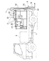
図1及び図2は、本発明の生ごみ資源化装置を例えば車両上に搭載した生ごみ処理車両の全体構成を示している。 1 and 2 show the overall configuration of a garbage disposal vehicle in which the garbage recycling device of the present invention is mounted on a vehicle, for example.
この生ごみ処理車両は、生ごみ資源化装置を搭載したもので、該生ごみ資源化装置は、車体1上に搭載されて生ごみを発酵処理して発酵・乾燥する発酵槽2と、当該発酵槽2に生ごみを投入する投入装置3とを備えている。
This garbage processing vehicle is equipped with a garbage recycling device, and the garbage recycling device is mounted on a vehicle body 1 to ferment and process garbage for fermentation and drying. And an
発酵槽2は、図3及び図4に示すようにその内部に攪拌装置4が設けられている。
As shown in FIGS. 3 and 4, the
攪拌装置4は、車両の前後方向に亘って設けられた攪拌軸41と、この攪拌軸41に放射状に延設けられた複数の攪拌棒42とを備えている。
The stirring
攪拌軸41は、図3に示すようにその前端部がスプロケットとチェーンからなる連繋手段43により発酵槽2の側部に設けられた電動モータ44の出力軸に連結され、電動モータ44の正逆方向への回転駆動により正逆方向に回転自在に設けられている。
As shown in FIG. 3, the
各攪拌棒42は、基端部が攪拌軸41に連結された連結部材42aと、連結部材42aの先端部に設けられた攪拌板42bとからなり、相反する方向へ直線状に延設された2本1組が所定の間隔を隔てて交互に90°ずらした状態で配置されている。
Each
そして、このように構成された攪拌装置4は、電動モータ44の正逆方向への回転駆動により発酵槽2内の内容物を両端部(前後端部)側から中央側にかき寄せるように攪拌棒42が回転する正回転と、当該内容物を中央側から両端部側に拡散させるように攪拌棒42が回転する逆回転とを行うようになされている。つまり、攪拌棒42の正逆方向への回転により上述したように内容物を搬送するように連結部材42aに対する各攪拌板42bの取付角度が予め調整されている。
The
また、発酵槽2の底部には図4に示すように排出スクリュー5が設けられている。排出スクリュー5は、発酵槽2から内容物を排出するためのもので、発酵槽2の底部一方側に前記攪拌装置4と平行な状態で前後方向に配設されている。
A
この排出スクリュー5は、図5に示すようにスクリュー軸5aの前端部に連結された電動モータ51により正逆方向に回転自在に設けられており、当該スクリュー軸5aの前端側途中部から後端にかけてブレード5bが設けられている。そして、ブレード5bが設けられた部分がカバー体52により囲繞され、当該カバー体52の全体が発酵槽2と連通孔21(図4参照)を通じて連通されている。
また、カバー体52の後端は排出口(排出部)53として開口されており、この排出口53が排出扉54により開閉自在になされている。
The
The rear end of the
ここで、上記ブレード5bは、前端部の部位5b1だけが他の部位5b2に対して逆向きに形成されている。この実施の形態では上記部位5b1は前端から1ピッチ分逆向きに形成されている。従って、例えば排出スクリュー5を排出方向に回転駆動(正回転)させた場合に、前端部の部位5b1以外の部位5b2が内容物を排出口53側に搬送し、部位5b1は内容物を排出方向とは逆方向に搬送する。また、排出スクリュー5を逆回転させた場合には各部位5b1、部位5b2が上述とは逆の方向に内容物を搬送することになる。
Here, in the
一方、前記投入装置3は、前記発酵槽2の上面後部に形成された投入口22から生ごみを投入するためのもので、発酵槽2の後部に設けられている。具体的には、投入装置3は、生ごみ容器などを保持する保持部材31と、保持部材31を地上付近から上昇させて投入口22に臨むように反転させる反転部材32とを備え、生ごみ容器を保持部材31に保持した状態で当該保持部材31を反転部材32により上方で反転させることで、生ごみ容器内の生ごみを投入口22を通じて発酵槽2内に投入する。
On the other hand, the
また、投入口22は開閉扉23により開閉自在になされており、この開閉扉23の先端部と上記保持部材31を連結ロッド24で連結することで、保持部材31の反転導入に連動して開閉扉23が開閉するように構成している。
The opening 22 is openable and closable by an opening / closing
そして、車体1の前部には発電機6が搭載されており、エンジン駆動でこの発電機6が発電する電力により攪拌装置4の電動モータ44、排出スクリュー5の電動モータ51、投入装置3の電動モータ33をそれぞれ駆動するようにしている。
A generator 6 is mounted on a front portion of the vehicle body 1. The
さらに、前記発酵槽2の底部外周面には図示しないヒータが敷設されるとともに、発酵槽2の側部にはブロワーヒータ25が設けられている。ヒータは発酵槽2の外部から発送槽2内を加熱し、ブロワーヒータ25は温風を発酵槽2内に直接吹き込んで、発酵槽2内の生ごみの発酵を促進させるようにしている。
Further, a heater (not shown) is laid on the outer peripheral surface of the bottom of the
なお、この際、ヒータ及びブロワーヒータ25の電源は上記発電機6の発電電力に余裕がある場合には当該発電機6により作動させればよい。また、発電機6の発電電力に余裕がない場合には、生ごみの回収時にはヒータ及びブロワーヒータ25を作動させることなく、電力設備が設置された基地でヒータ及びブロワーヒータ25を作動させることになる。
At this time, the power supply of the heater and the
この他、発電機6そのものが発熱体であるため、この発電機6の発熱を発酵槽2内に送り込み走行中の加温手段として活用することも可能である。
In addition, since the generator 6 itself is a heating element, the heat generated by the generator 6 can be fed into the
さらに、車両に発電機を搭載することなく、車両のエンジン動力を動力取出装置を介して取出し油圧駆動により攪拌装置4、排出スクリュー5、投入装置3を作動させることも可能であるが、この場合にはヒータ及びブロワーヒータ25の作動は上述した基地で行うことになる。
Further, it is also possible to take out the engine power of the vehicle via a power take-out device without operating a generator on the vehicle, and to operate the
次に、このように構成された本発明の生ごみ資源化装置を搭載した生ごみ処理車両により生ごみを発酵処理して排出する場合の手順について説明する。 Next, a description will be given of a procedure when the garbage is fermented and discharged by the garbage processing vehicle equipped with the garbage recycling apparatus of the present invention configured as described above.
まず、生ごみ処理車両で回収場に出向き、当該回収場で生ごみを投入装置3によって投入口22を通じて発酵槽2内に投入する。
First, the garbage disposal vehicle goes to a collection site, where garbage is put into the
発酵槽2では、予め槽内に投入されている好気性菌や、おが屑等の床材と生ごみとが攪拌装置4により混合攪拌され、好気性菌により生ごみの有機成分が炭酸ガスと水蒸気に分解される。
In the
このように攪拌装置4による生ごみの混合攪拌を行いながら、各回収場での生ごみの回収を完了すると生ごみ処理車両を基地に戻す。続いて、基地では、当該基地に設置している電源設備を利用して攪拌装置4を駆動させながらヒータ及びブロワーヒータ25によって発酵槽2を加温することで発酵槽2内の生ごみ(内容物)の発酵を促進させると同時に乾燥を行い、堆肥化或いは飼料化させる。なお、前述したように発電機6の発電電力に余裕がある場合には、生ごみ処理車両による生ごみ回収中においてもヒータ及びブロワーヒータ25によって発酵槽2を加温することでさらに生ごみの発酵・乾燥を促進させることができ、堆肥化或いは飼料化を効率良く行うことができる。
When the collection of the garbage at each collection site is completed while mixing and stirring the garbage by the stirring
そして、このようにして発酵槽2内の生ごみを堆肥化或いは飼料化した内容物(処理物)は発酵槽2内から排出スクリュー5を通じて排出口53から外部に排出される。
Then, the contents (processed material) obtained by composting or converting the garbage in the
ここで、上述したように生ごみを混合攪拌、並びに排出する上で攪拌装置4と排出スクリュー5とは具体的には以下のように駆動している。
Here, as described above, in mixing and stirring and discharging the garbage, the stirring
まず、生ごみを混合攪拌する場合には、攪拌装置4は、正回転と逆回転とを交互に繰り返し、これにより内容物を発酵槽2内において前後端部側から中央側にかき寄せる動作と、内容物を中央側から前後端部側に拡散させる動作とを交互に行いながら当該内容物を混合攪拌している。これとともに排出スクリュー5は、攪拌装置4の正回転時には停止しており、攪拌装置4の逆回転時のみ逆回転している。
First, when mixing and stirring garbage, the
つまり、搬送装置4により内容物を中央側から前後端部側に拡散させているときにのみ搬出スクリュー5が排出方向とは逆方向へ内容物を搬送しており、これにより排出スクリュー5に内容物が詰まることなく当該内容物の混合攪拌を効率良く十二分に行うことができる。
That is, the
この際、排出スクリュー5を逆回転させることによって、通常では内容物が排出スクリュー5の前端部に搬送されて当該前端部に押し込まれることになる。しかしながら、この排出スクリュー5では前端部のブレード5b1を逆向きにしているため、当該ブレード5b1により排出方向に移送される内容物とブレード5b2により前端部側に移送される内容物がぶつかり合うことになり、これによりブレード5b間での内容物の詰まりを防止することができる。
At this time, by rotating the
また、このような内容物の混合攪拌は、排出扉54が排出口53を閉塞している時のみ行うように、排出扉54の閉塞を近接センサ(図示省略)等の検出器が検出した時に攪拌装置4及び排出スクリュー5が駆動するようにしている。これにより排出扉54が開いた状態での攪拌動作による排出口53からの内容物の予期せぬ排出を防止することができる。
In addition, such mixing and stirring of the contents is performed only when the
次に、内容物を排出する際には、排出扉54を解放させた状態で排出スクリュー5を正回転させて内容物を排出口53に搬送して排出する。この際、攪拌装置4は正回転しており、この攪拌装置4により発酵槽2内の内容物を前後端部側から中央側にかき寄せながら連通孔21を通じて排出スクリュー5に導入し、当該排出スクリュー5によって排出するようにしている。これにより発酵槽2の前部側に貯留されていた内容物も排出スクリュー5に円滑に導入され、発酵槽2内の略全部の内容物を残すことなく円滑に排出することができる。なお、内容物を排出する際には、前述した攪拌時のような排出扉54の解放による検出器の検出の有無に関わらず、排出スイッチの排出指令により攪拌装置4及び排出スクリュー5が作動するようになっている。
Next, when discharging the contents, the
なお、上述した実施形態は、あくまでも本発明の好適な実施態様を示すものであって、本発明はこれに限定されることなく、その範囲内において種々設計変更可能である。 Note that the above-described embodiment merely shows a preferred embodiment of the present invention, and the present invention is not limited to this, and various design changes can be made within the scope.
例えば、排出スクリュー5は、ブレード5bを有する部分を発酵槽2の前後方向全体ではなく、後端部寄りに設けて上記発酵槽2に連通させたものについて説明したが、ブレード5bを有する部分を発酵槽2の全長に亘って設けて当該発酵槽2の全長に亘って連通させて内容物を搬送するようにしてもよく、これにより搬出スクリュー5による排出能力は向上する。
For example, the
また、排出スクリュー5の取付位置は、本実施の形態のように底部側方に限らず底部真下に設けてもよい。
Further, the mounting position of the
さらに、ブレード5bの部位5b1は、1ピッチに限らずブレード5bの長さなど設備に応じて適宜に設定すればよい。
Further, the portion 5b1 of the
また、攪拌装置4も、本実施の形態のように1つに限らず2つを併設するようにしてもよい。この場合、発酵槽2の底部を2つの攪拌装置4に対応した形状にするとともに、各攪拌装置4に対応して排出スクリュー5をそれぞれ設けるのが好ましい。
Further, the number of the
さらに、本実施の形態では、生ごみ資源化装置を車両に搭載したものについて述べたが、これに限らず、生ごみ資源化装置を地上の基台上などに設置するようにしてもよい。この場合、生ごみの回収は別な手段で行えばよい。 Further, in the present embodiment, the description has been given of the case where the garbage recycling device is mounted on the vehicle, but the present invention is not limited to this, and the garbage recycling device may be installed on a ground base or the like. In this case, the garbage may be collected by another means.
2 発酵槽
4 攪拌装置
5 排出スクリュー
5b1 ブレード
53 排出口(排出部)
2
Claims (5)
Priority Applications (1)
| Application Number | Priority Date | Filing Date | Title |
|---|---|---|---|
| JP2003315471A JP2004276010A (en) | 2003-02-27 | 2003-09-08 | Apparatus for resource-recycling garbage |
Applications Claiming Priority (2)
| Application Number | Priority Date | Filing Date | Title |
|---|---|---|---|
| JP2003051032 | 2003-02-27 | ||
| JP2003315471A JP2004276010A (en) | 2003-02-27 | 2003-09-08 | Apparatus for resource-recycling garbage |
Publications (1)
| Publication Number | Publication Date |
|---|---|
| JP2004276010A true JP2004276010A (en) | 2004-10-07 |
Family
ID=33301813
Family Applications (1)
| Application Number | Title | Priority Date | Filing Date |
|---|---|---|---|
| JP2003315471A Pending JP2004276010A (en) | 2003-02-27 | 2003-09-08 | Apparatus for resource-recycling garbage |
Country Status (1)
| Country | Link |
|---|---|
| JP (1) | JP2004276010A (en) |
Cited By (3)
| Publication number | Priority date | Publication date | Assignee | Title |
|---|---|---|---|---|
| JP2016159257A (en) * | 2015-03-04 | 2016-09-05 | 株式会社カワタ | Feeder |
| CN107754636A (en) * | 2017-11-16 | 2018-03-06 | 管远轮 | A kind of mixer |
| CN107998970A (en) * | 2018-01-19 | 2018-05-08 | 南昌诺义弘科技有限公司 | A kind of electrolyte making device |
-
2003
- 2003-09-08 JP JP2003315471A patent/JP2004276010A/en active Pending
Cited By (3)
| Publication number | Priority date | Publication date | Assignee | Title |
|---|---|---|---|---|
| JP2016159257A (en) * | 2015-03-04 | 2016-09-05 | 株式会社カワタ | Feeder |
| CN107754636A (en) * | 2017-11-16 | 2018-03-06 | 管远轮 | A kind of mixer |
| CN107998970A (en) * | 2018-01-19 | 2018-05-08 | 南昌诺义弘科技有限公司 | A kind of electrolyte making device |
Similar Documents
| Publication | Publication Date | Title |
|---|---|---|
| JP2006255550A (en) | Garbage drying machine | |
| KR101719753B1 (en) | Organic waste fermentation device | |
| JP2004276010A (en) | Apparatus for resource-recycling garbage | |
| JP2008086915A (en) | Garbage disposal apparatus | |
| JP4478005B2 (en) | Egg disposal machine | |
| JP3850283B2 (en) | Organic waste treatment equipment | |
| JP2003245635A (en) | Garbage disposal apparatus | |
| KR19990084655A (en) | Feed manufacturing device using food waste | |
| JP2005034813A (en) | Garbage treating apparatus | |
| JP3247883B2 (en) | Transport processing equipment | |
| JP4560961B2 (en) | Garbage processing machine | |
| JP3300832B2 (en) | Garbage processing machine | |
| JP4049983B2 (en) | Composting material manufacturing equipment | |
| CN1120760C (en) | Equipment for disposal of organic matter | |
| CN214915074U (en) | High-efficient kitchen remains turns over a heap stirring degradation machine | |
| JP3105629U (en) | Garbage processing equipment | |
| JPH0929213A (en) | Waste treatment apparatus | |
| JP2005138025A (en) | Organic waste treatment apparatus | |
| JP2006263636A (en) | Garbage disposal apparatus | |
| JP2003181429A (en) | Garbage disposal apparatus | |
| JP2007160284A (en) | Organic waste treatment apparatus | |
| JP2006326516A (en) | Organic waste treatment apparatus | |
| JP2002066288A (en) | Apparatus for treating garbage, or the like | |
| JP2007029842A (en) | Volume reduction method of organic waste and its device | |
| JP2000095589A (en) | Composting equipment |