JP2004273260A - Fuel cell and method of producing it - Google Patents
Fuel cell and method of producing it Download PDFInfo
- Publication number
- JP2004273260A JP2004273260A JP2003061976A JP2003061976A JP2004273260A JP 2004273260 A JP2004273260 A JP 2004273260A JP 2003061976 A JP2003061976 A JP 2003061976A JP 2003061976 A JP2003061976 A JP 2003061976A JP 2004273260 A JP2004273260 A JP 2004273260A
- Authority
- JP
- Japan
- Prior art keywords
- film
- electrode
- conductive material
- power generation
- fuel cell
- Prior art date
- Legal status (The legal status is an assumption and is not a legal conclusion. Google has not performed a legal analysis and makes no representation as to the accuracy of the status listed.)
- Granted
Links
Images


Classifications
-
- Y—GENERAL TAGGING OF NEW TECHNOLOGICAL DEVELOPMENTS; GENERAL TAGGING OF CROSS-SECTIONAL TECHNOLOGIES SPANNING OVER SEVERAL SECTIONS OF THE IPC; TECHNICAL SUBJECTS COVERED BY FORMER USPC CROSS-REFERENCE ART COLLECTIONS [XRACs] AND DIGESTS
- Y02—TECHNOLOGIES OR APPLICATIONS FOR MITIGATION OR ADAPTATION AGAINST CLIMATE CHANGE
- Y02E—REDUCTION OF GREENHOUSE GAS [GHG] EMISSIONS, RELATED TO ENERGY GENERATION, TRANSMISSION OR DISTRIBUTION
- Y02E60/00—Enabling technologies; Technologies with a potential or indirect contribution to GHG emissions mitigation
- Y02E60/30—Hydrogen technology
- Y02E60/50—Fuel cells
Abstract
Description
【0001】
【発明の属する技術分野】
本発明は、電解質をアノード側電極とカソード側電極とで挟んで構成される発電部を備え、複数の前記発電部が平面状に配設される燃料電池およびその製造方法に関する。
【0002】
【従来の技術】
例えば、固体高分子形燃料電池は、高分子イオン交換膜(陽イオン交換膜)からなる電解質膜(電解質)を採用している。この電解質膜の両側に、それぞれカーボンを主体とする基材に貴金属系の電極触媒層を接合したアノード側電極およびカソード側電極を設けた電解質・電極構造体(発電部)を、セパレータ(バイポーラ板)によって挟持した単位セルを備えている。通常、この単位セルは、所定数だけ積層することにより燃料電池スタックとして使用されている。
【0003】
この種の燃料電池において、アノード側電極に供給された燃料ガス、例えば、主に水素を含有するガス(以下、水素含有ガスともいう)は、電極触媒上で水素がイオン化され、電解質を介してカソード側電極側へと移動する。その間に生じた電子は外部回路に取り出され、直流の電気エネルギとして利用される。なお、カソード側電極には、酸化剤ガス、例えば、主に酸素を含有するガスあるいは空気(以下、酸素含有ガスともいう)が供給されているために、このカソード側電極において、水素イオン、電子および酸素が反応して水が生成される。
【0004】
ところで、他の燃料電池では、複数の単位セルを平面状に1列または複数列に配設し、各単位セル同士を電気的に直列に接続した平面形燃料電池が採用されている。例えば、図15に示す平面形燃料電池(特許文献1参照)では、電解質層1a〜1dを挟んで空気極(カソード極)2a〜2dと燃料極(アノード極)3a〜3dとを対設した複数個の単位セル4a〜4dを、同じ極が同じ面に並ぶように平面に配列している。単位セル4a〜4dは、導電性のZ字状接続板5a〜5cにより接続されて、各単位セル4a〜4dが電気的に直列に接続されている。
【0005】
具体的には、Z字状接続板5aが単位セル4aの空気極2aと単位セル4bの燃料極3bとを接続し、Z字状接続板5bが単位セル4bの空気極2bと単位セル4cの燃料極3cとを接続し、Z字状接続板5cが単位セル4cの空気極2cと単位セル4dの燃料極3dとを接続している。単位セル4aの燃料極3aは、陰極側電流端子6aに接続される一方、単位セル4dの空気極2dは、陽極側電流端子6bに接続されている。
【0006】
【特許文献1】
特開2002−56855号公報(図1)
【0007】
【発明が解決しようとする課題】
しかしながら、上記の特許文献1では、各単位セル4a〜4dを電気的に直列に接続するために、専用のZ字状接続板5a〜5cが用いられており、前記Z字状接続板5a〜5cが、空気極2a〜2dと燃料極3a〜3dとに跨っている。このため、空気極2a〜2dと燃料極3a〜3dとの間におけるシール構造等の信頼性を確保することが困難になるという問題が指摘されている。
【0008】
しかも、燃料電池の厚さ方向(矢印T方向)の寸法が拡大してしまい、燃料電池全体の小型化を図ることができないという問題がある。さらに、各単位セル4a〜4dは、基本的に独立した部品であり、基準となる面がないために前記単位セル4a〜4d同士の位置精度が得られないという問題がある。
【0009】
本発明はこの種の問題を解決するものであり、複数の発電部を電気的に直列に接続するとともに、簡単かつコンパクトな構成で、シール性の向上を図って所望の電圧を確保することが可能な燃料電池およびその製造方法を提供することを目的とする。
【0010】
【課題を解決するための手段】
本発明の請求項1に係る燃料電池では、電解質をアノード側電極とカソード側電極とで挟んで構成される複数の発電部が、単一の多孔質非導電性フィルム上に配設されるとともに、各発電部のそれぞれ同一の極側が前記多孔質非導電性フィルムに対向している。すなわち、各発電部は、それぞれ同一の極側が単一の多孔質非導電性フィルムの同一の面に配置されている。
【0011】
そして、隣接する一方の発電部のアノード側電極が、第1フィルム状導電材に電気的に接続されるとともに、隣接する他方の発電部のカソード側電極が、第2フィルム状導電材に電気的に接続される。その際、第1または第2フィルム状導電材は、電解質から離間する位置で前記第1および第2フィルム状導電材を電気的に接続する膨出部を設けている。
【0012】
このため、隣接する発電部同士は、第1および第2フィルム状導電材によりアノード側電極とカソード側電極とが接続され、全体として複数の発電部が電気的に直列に接続される。
【0013】
具体的には、隣接する第1および第2の発電部において、前記第1の発電部のアノード側電極に接続された第1フィルム状導電材と、前記第2の発電部のカソード側電極に接続された第2フィルム状導電材とが、電気的に結合される。従って、第1の発電部と第2の発電部とは、電気的に接続される。
【0014】
さらに、第2の発電部のアノード側電極に接続された第1フィルム状導電材は、前記第2の発電部に隣接する第3の発電部のカソード側電極に接続された第2フィルム状導電材と電気的に結合される。従って、第2の発電部と第3の発電部とは、電気的に接続され、第1の発電部、第2の発電部および第3の発電部は、電気的に直列に接続される。
【0015】
これにより、従来の専用のZ字状接続板が不要になるため、構成が簡素化されて経済的であるとともに、シール構造等の信頼性が有効に向上する。しかも、燃料電池全体の構成が簡素化される他、燃料電池の小型化が容易に図られる。
【0016】
また、本発明の請求項2に係る燃料電池では、第1フィルム状導電材は、アノード側電極のアノード拡散層と略同一平面上に構成されるとともに、第2フィルム状導電材は、カソード側電極のカソード拡散層と略同一平面上に構成される。このため、燃料電池は、厚さ方向(積層方向)の寸法が可及的に薄肉化され、燃料電池全体の小型化が遂行可能になる。
【0017】
さらに、本発明の請求項3に係る燃料電池では、第1フィルム状導電材は、金属フィルムで構成されるとともに、第2フィルム状導電材は、樹脂と電気導電材との複合材で構成される。一方、本発明の請求項4に係る燃料電池では、第1フィルム状導電材は、樹脂と電気導電材との複合材で構成されるとともに、第2フィルム状導電材は、金属フィルムで構成される。
【0018】
その際、金属フイルムは、製作時の取り扱い性に優れる一方、複合材は、位置精度を厳密に維持する必要がない。従って、燃料電池の製造作業が簡便に遂行されるとともに、構成の簡素化および小型化が容易に図られる。しかも、カソード側電極とアノード側電極とは、いずれを上下に設定してもよく、汎用性に優れる。
【0019】
さらにまた、本発明の請求項5に係る燃料電池の製造方法では、単一の多孔質非導電性フィルム上に、第1フィルム状導電材が固着された後、前記多孔質非導電性フィルム上に、隣接する第1および第2の発電部を構成する一方の電極(例えば、アノード側電極)が設けられるとともに、前記第2の発電部を構成する一方の電極が前記第1フィルム状導電材と電気的に接続される。
【0020】
次いで、一方の電極に、それぞれ第1フィルム状導電材に一部を重ね合わせて第1および第2の電解質が設けられ、前記第1および第2の電解質には、第1および第2の発電部を構成する他方の電極(例えば、カソード側電極)が設けられる。そして、第1の発電部を構成する他方の電極と第1フィルム状導電材とが、第2フィルム状導電材を介して電気的に接続されるとともに、前記第2フィルム状導電材上および該第2フィルム状導電材と前記他方の電極との隙間を覆って絶縁樹脂が設けられる。
【0021】
このように、多孔質非導電性フィルム上に構成材料を、順次、重ねることによって燃料電池が製造されるため、この燃料電池の製造作業が有効に簡素化される。しかも、多孔質非導電性フィルムは、製造作業時の基準平面を構成しており、各発電部の位置決め精度が良好に向上する。さらに、平面上の界面でシールされるため、積層方向に貫通するシール必要部位がなく、所望のシール性能を確実に得ることができる。
【0022】
また、本発明の請求項6に係る燃料電池の製造方法では、第2の発電部の一方の電極を構成する拡散層が、第1フィルム状導電材と電気的に接続されるとともに、前記第1の発電部の他方の電極を構成する拡散層が、第2フィルム状導電材と電気的に接続される。これにより、第1の発電部の他方の電極と第2の発電部の一方の電極とは、コンパクトな構成で、電気的に確実に接続される。
【0023】
【発明の実施の形態】
図1は、本発明の第1の実施形態に係る燃料電池10の要部分解斜視説明図であり、図2は、前記燃料電池10の要部断面説明図である。
【0024】
燃料電池10は、MEA(Membrane and Electrode Assembly)ユニット12と、このMEAユニット12の両面に配置される第1および第2セパレータ14、16とを備える。
【0025】
燃料電池10の矢印B方向の一端縁部には、積層方向である矢印A方向に連通して、燃料ガス、例えば、水素含有ガスを供給するための燃料ガス入口連通孔18aと、酸化剤ガス、例えば、酸素含有ガスを供給するための酸化剤ガス入口連通孔20aとが、矢印C方向一端側に配列して設けられる。燃料電池10の矢印B方向の一端縁部には、矢印A方向に連通して、燃料ガスを排出するための燃料ガス出口連通孔18bと、酸化剤ガスを排出するための酸化剤ガス出口連通孔20bとが、矢印C方向他端側に配列して設けられる。
【0026】
MEAユニット12は、多孔質樹脂フィルム(多孔質非導電性フィルム)22を備える。この多孔質樹脂フィルム22の面内には、複数の電解質・電極構造体(発電部)24(1)〜24(n)が所定の数ずつ配列して設けられる。
【0027】
図3に示すように、多孔質樹脂フィルム22上には、後述する電極が設けられていない部分に対応してラミネート窓枠フイルム、例えば、シリコンフィルム26が設けられる。この多孔質樹脂フィルム22には、所定の位置に複数の孔部27が形成される(図1参照)。
【0028】
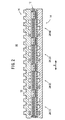
図3および図4に示すように、電解質・電極構造体24(1)は、多孔質樹脂フィルム22上に設けられるアノード側電極28と、前記アノード側電極28上に積層される高分子電解質29と、前記高分子電解質29上に積層されるカソード側電極30とを備える。アノード側電極28は、導電性のアノード拡散層28aと、アノード電極触媒層28bとを設ける一方、カソード側電極30は、導電性のカソード拡散層30aと、カソード電極触媒層30bとを備える。
【0029】
高分子電解質29は、電解質・電極構造体24(1)に隣接する電解質・電極構造体24(2)側に突出する端部29aを設け、この端部29aは、多孔質樹脂フィルム22上のシリコンフィルム26に積層された金属フィルム(第1フィルム状導電材)32の一端部上に積層される。
【0030】
金属フィルム32の他端は、電解質・電極構造体24(2)のアノード側電極28近傍に延在しており、この他端には、前記アノード側電極28を構成するアノード拡散層28aから電解質・電極構造体24(1)側に突出する端部28aaが積層される。電解質・電極構造体24(2)の高分子電解質29は、電解質・電極構造体24(1)側に突出してアノード拡散層28aの端部28aaから金属フィルム32上の所定の位置まで覆う端部29bを設ける。互いに対向する高分子電解質29の端部29a、29b間には、円柱状の隙間34aが形成される。
【0031】
電解質・電極構造体24(1)のカソード側電極30を構成するカソード拡散層30aに導電材(第2フィルム状導電材)36の一端が電気的に接続される。この導電材36は、樹脂と電気導電材、例えば、カーボンとの複合材で構成され、電解質・電極構造体24(1)、24(2)間に設けられる。導電材36は、電解質・電極構造体24(2)のカソード側電極30との間に所定の隙間34bを設けるとともに、高分子電解質29の端部29a、29b間の隙間34aに突出する膨出部36aを有する。
【0032】
この膨出部36aは、金属フィルム32に電気的に接続され、電解質・電極構造体24(1)のカソード側電極30と、電解質・電極構造体24(2)のアノード側電極28とが、電気的に接続される。導電材36上およびこの導電材36と電解質・電極構造体24(2)のカソード側電極30との隙間34bとを覆って絶縁樹脂38が設けられる。
【0033】
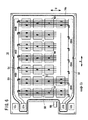
第1および第2セパレータ14、16は、非導電性の伝熱材補強プラスチック製成形体で構成される。図1および図5に示すように、第1セパレータ14のMEAユニット12に対向する面14aには、矢印C方向一端側に矢印B方向に延在して供給マニホールド40が形成されるとともに、矢印C方向他端側に矢印B方向に延在して排出マニホールド42が形成される。供給マニホールド40は、凹部形状を有しており、燃料ガス入口連通孔18aに連通する。排出マニホールド42は、同様に凹部形状を有しており、燃料ガス出口連通孔18bに連通する。
【0034】
面14aには、供給マニホールド40から排出マニホールド42に向かって燃料ガスを供給するための燃料ガス流路44が形成される。この燃料ガス流路44は、矢印C方向に延在して供給マニホールド40と排出マニホールド42とに連通する複数本の流路溝を備えている。面14aには、電解質・電極構造体24(1)〜24(n)の各アノード側電極28を収容するための矩形状溝部46が形成されるとともに、所定の位置に複数のシール付きねじ孔48が形成される。
【0035】
面14aには、燃料ガス入口連通孔18a、燃料ガス出口連通孔18b、供給マニホールド40、排出マニホールド42および燃料ガス流路44を覆ってシール50が焼き付け等により設けられる。第1セパレータ14は、−(マイナス)側の端子52が電解質・電極構造体24(1)のアノード側電極28に接続可能に設けられる。
【0036】
図6に示すように、第2セパレータ16のMEAユニット12に対向する面16aには、酸化剤ガス入口連通孔20aに連通して矢印B方向に延在する供給マニホールド54と、酸化剤ガス出口連通孔20bに連通して矢印B方向に延在する排出マニホールド56とが形成される。供給マニホールド54と排出マニホールド56とは、矢印C方向に延在する複数本の流路溝を備えた酸化剤ガス流路58を介して連通する。
【0037】
面16aには、酸化剤ガス入口連通孔20a、酸化剤ガス出口連通孔20b、供給マニホールド54、排出マニホールド56および酸化剤ガス流路58を覆ってシール59が焼き付け等により設けられる。
【0038】
面16aには、電解質・電極構造体24(1)〜24(n)の各カソード側電極30に対応して矩形状の溝部60が形成される。面16aには、所定の位置にシール付き孔部62が形成されており、図1に示すように、前記シール付き孔部62からMEAユニット12の孔部27を貫通して第2セパレータ16のシール付きねじ孔48に締結ねじ64が螺合して燃料電池10が一体化される。第2セパレータ16には、電解質・電極構造体24(n)のカソード側電極30に接続可能な+(プラス)側の端子66が設けられる。
【0039】
図1に示すように、第2セパレータ16の面16aとは反対側の面16bには、矢印C方向に延在してリブ70が設けられ、前記リブ70間には、冷却媒体流路72が形成される。
【0040】
このように構成される燃料電池10を製造する作業について、以下に説明する。
【0041】
なお、隣接する電解質・電極構造体24(1)、24(2)を製造する作業について詳細に説明し、電解質・電極構造体24(3)〜24(n)の製造作業については、その詳細な説明は省略する。
【0042】
まず、MEAユニット12全体の基準平面を構成する多孔質樹脂フィルム22が形成され、この多孔質樹脂フィルム22上に、電解質・電極構造体24(1)〜24(n)に対応する打ち抜き窓が設けられたラミネート窓枠フィルムとしてシリコンフィルム26が設けられる。
【0043】
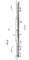
そこで、図7に示すように、多孔質樹脂フィルム22上に接着剤80を塗布し、この接着剤80によって金属フィルム32が貼り付けられる。そして、多孔質樹脂フィルム22上には、マスキング枠82を介してアノード拡散層(例えば、カーボンと樹脂)28aが塗布され、このアノード拡散層28aは乾燥される。その際、電解質・電極構造体24(2)を構成するアノード拡散層28aの端部28aaは、金属フィルム32上に積層されて電気的に接続される。
【0044】
次いで、図8に示すように、マスキング枠84が配置され、このマスキング枠84を用いてアノード電極触媒層28bがアノード拡散層28a上に塗布される。このアノード電極触媒層28bは乾燥される。
【0045】
さらに、図9に示すように、マスキング枠(スクリーン等)86を用いて高分子電解質29が塗布される。具体的には、マスキング枠86が隙間34aに対応する位置に配置されており、電解質・電極構造体24(1)では、アノード電極触媒層28b上に設けられた高分子電解質29の端部29aが、金属フィルム32の端部上まで延在する。一方、電解質・電極構造体24(2)では、アノード電極触媒層28bから金属フィルム32上に高分子電解質29が設けられるとともに、前記高分子電解質29の端部29bが前記金属フィルム32上の所定の位置まで延在する。従って、端部29a、29b間には、マスキング枠86により円柱状の隙間34aが形成される。
【0046】
高分子電解質29が乾燥された後、図10に示すように、マスキング枠84を用いて、前記高分子電解質29上にカソード電極触媒層30bが塗布される。カソード電極触媒層30bが乾燥されると、同様にマスキング枠84を用いて、前記カソード電極触媒層30b上にカソード拡散層(例えば、カーボンと樹脂)30aが塗布されて、このカソード拡散層30aが乾燥される。
【0047】
次に、図11に示すように、マスキング枠88を用いて、導電材36が塗布され、この導電材36に乾燥処理が施される。導電材36は、電解質・電極構造体24(1)を構成するカソード側電極30のカソード拡散層30aに電気的に接続されるとともに、高分子電解質29の端部29a、29b間に形成された円形状の隙間34aに充填される膨出部36aを備える。この膨出部36aは、金属フィルム32に電気的に接続され、電解質・電極構造体24(1)のカソード側電極30と、電解質・電極構造体24(2)のアノード側電極28とが、導電材36および金属フィルム32を介して電気的に接続される。
【0048】
導電材36を乾燥させた後、図12に示すように、マスキング枠90が用いられ、絶縁樹脂38が塗布される。この絶縁樹脂38は、導電材36上から前記導電材36と電解質・電極構造体24(2)のカソード側電極30との隙間34bに充填され、電解質・電極構造体24(1)、24(2)の各カソード側電極30同士が電気的に絶縁される。これにより、多孔質樹脂フィルム22上には、隣接する電解質・電極構造体24(1)、24(2)が電気的に直列に接続されて製造される。
【0049】
すなわち、図13に示すように、電解質・電極構造体24(1)を構成するカソード側電極30の端部と導電材36の端部との間には、電子導電繋ぎ部92aが設けられ、前記導電材36の円柱状の膨出部36aの端面と金属フィルム32の界面には、電子導電繋ぎ部92bが設けられる。さらに、金属フィルム32と電解質・電極構造体24(2)のアノード拡散層28aの端部28aaとの界面には、電子導電繋ぎ部92cが設けられる。
【0050】
この場合、第1の実施形態では、図3に示すように、金属フィルム32および導電材36を介して、電解質・電極構造体24(1)のカソード側電極30と、電解質・電極構造体24(2)のアノード側電極28とが、電気的に直列に接続されるため、従来の専用のZ字状接続板が不要になる。これにより、電気接続構造が簡素化されて経済的であるとともに、燃料電池10全体の構成を小型化かつ簡素化することができるという効果が得られる。
【0051】
さらに、金属フィルム32は、製造時の取り扱い性に優れる一方、導電材36は、位置精度を厳密に維持する必要がない。従って、燃料電池10の製造作業が簡便に遂行されるとともに、構成の簡素化および小型化が容易に図られる。特に、金属フィルム32および導電材36は、アノード側電極28およびカソード側電極30と略同一平面上に構成されており、MEAユニット12は、厚さ方向の寸法が可及的に薄肉化される。従って、燃料電池10全体の小型化が一層確実に遂行可能になる。
【0052】
しかも、燃料ガスと酸化剤ガスとのシール構造は、高分子電解質29の端部29aとシリコンフィルム26および金属フィルム32との界面に沿った面方向の距離H1の範囲、および前記高分子電解質29の端部29bの界面に沿った距離H2の範囲内にわたっている。このため、反応ガスのシール構造として、信頼性が有効に向上するという利点がある。
【0053】
また、第1の実施形態では、多孔質樹脂フィルム22上に構成材料を、順次、重ねることによって、MEAユニット12が製造される。これにより、燃料電池10全体の製造作業が有効に簡素化される。しかも、多孔質樹脂フィルム22は、製造作業時の基準平面を構成しており、電解質・電極構造体24(1)〜24(n)の位置決め精度が良好に向上するとともに、製造作業の簡素化が図られるという効果がある。
【0054】
次に、上記の燃料電池10の動作について説明する。
【0055】
まず、図1に示すように、酸化剤ガス入口連通孔20aに酸素含有ガス等の酸化剤ガスが供給されるとともに、燃料ガス入口連通孔18aに水素含有ガス等の燃料ガスが供給される。また、冷却媒体流路72には、純水やエチレングリコール、オイル等の冷却媒体が供給される。
【0056】
このため、酸化剤ガスは、図6に示すように、第2セパレータ16の面16aに形成される供給マニホールド54に一旦導入された後、酸化剤ガス流路58に供給される。酸化剤ガスは、複数の流路溝を介して矢印C方向に移動し、電解質・電極構造体24(1)〜24(n)の各カソード側電極30に供給される。未使用の酸化剤ガスは、排出マニホールド56から酸化剤ガス出口連通孔20bに排出される。
【0057】
一方、燃料ガスは、図5に示すように、第1セパレータ14の面14bに形成される供給マニホールド40に導入され、この供給マニホールド40に連通する燃料ガス流路44に供給される。この燃料ガス流路44では、燃料ガスが矢印C方向に移動しながら、電解質・電極構造体24(1)〜24(n)の各アノード側電極28に供給される。未使用の燃料ガスは、排出マニホールド42を通って燃料ガス出口連通孔18bから排出される。
【0058】
従って、電解質・電極構造体24(1)〜24(n)では、各カソード側電極30に供給される酸化剤ガスと、各アノード側電極28に供給される燃料ガスとが電気化学反応により消費され、発電が行われる。これにより、端子52、66間には、全ての発電部である電解質・電極構造体24(1)〜24(n)が電気的に直列に接続され、所望の電圧を発生させることができる。
【0059】
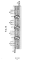
図14は、本発明の第2の実施形態に係る燃料電池を構成するMEAユニット100の接続状態を示す説明図である。なお、第1の実施形態に係る燃料電池10を構成するMEAユニット12と同一の構成要素には同一の参照符号を付して、その詳細な説明は省略する。
【0060】
MEAユニット100を構成する電解質・電極構造体102(1)は、多孔質樹脂フィルム22上に設けられるカソード側電極30と、前記カソード側電極30上に積層される高分子電解質29と、前記高分子電解質29上に積層されるアノード側電極28とを備える。
【0061】
電解質・電極構造体102(1)に隣接する電解質・電極構造体102(2)は、カソード側電極30を構成するカソード拡散層30aから電解質・電極構造体102(1)側に突出する端部30aaが、金属フィルム(第2フィルム状導電材)32上に積層される。電解質・電極構造体102(1)のアノード側電極28を構成するアノード拡散層28aに導電材(第1フィルム状導電材)36の一端が電気的に接続される。
【0062】
これにより、第2の実施形態では、多孔質樹脂フィルム22に対してカソード側電極30を下、アノード側電極28を上に配置しており、第1の実施形態とは逆に構成されているが、第1の実施形態と同様の効果を得ることができる。
【0063】
【発明の効果】
本発明に係る燃料電池では、従来の専用のZ字状接続板が不要になり、構成が簡素化されて経済的であるとともに、シール構造等の信頼性が有効に向上する。しかも、燃料電池全体の構成が簡素化される他、前記燃料電池の小型化が容易に図られる。
【0064】
また、本発明に係る燃料電池の製造方法では、多孔質非導電性フィルム上に構成材料を、順次、重ねることにより、燃料電池の製造作業が有効に簡素化される。しかも、多孔質非導電性フイルムは、製造作業時の基準平面を構成しており、各発電部の位置決め精度が有効に向上する。さらに、平面上の界面でシールされるため、積層方向に貫通するシール必要部位がなく、所望のシール性能を確実に得ることができる。
【図面の簡単な説明】
【図1】本発明の第1の実施形態に係る燃料電池の要部分解斜視説明図である。
【図2】前記燃料電池の要部断面説明図である。
【図3】前記燃料電池を構成するMEAユニットの接続状態を示す説明図である。
【図4】前記MEAユニットの正面図である。
【図5】前記燃料電池を構成する第1セパレータの正面図である。
【図6】前記燃料電池を構成する第2セパレータの正面図である。
【図7】多孔質樹脂フィルム上にアノード拡散層を形成する際の説明図である。
【図8】前記アノード拡散層上にアノード電極触媒層を形成する際の説明図である。
【図9】高分子電解質を形成する際の説明図である。
【図10】カソード電極触媒層およびカソード拡散層を形成する際の説明図である。
【図11】導電材を形成する際の説明図である。
【図12】絶縁樹脂を形成する際の説明図である。
【図13】電子導電繋ぎ部の斜視説明図である。
【図14】本発明の第2の実施形態に係る燃料電池を構成するMEAユニットの接続状態を示す説明図である。
【図15】特許文献1に係る平面形燃料電池の要部断面説明図である。
【符号の説明】
10…燃料電池 12、100…MEAユニット
14、16…セパレータ 18a…燃料ガス入口連通孔
18b…燃料ガス出口連通孔 20a…酸化剤ガス入口連通孔
20b…酸化剤ガス出口連通孔 22…多孔質樹脂フィルム
24(1)〜24(n)、102(1)、102(2)…電解質・電極構造体
26…シリコンフィルム 28…アノード側電極
28a…アノード拡散層 28aa、29a、29b、30aa…端部
28b…アノード電極触媒層 29…高分子電解質
30…カソード側電極 30a…カソード拡散層
30b…カソード電極触媒層 32…金属フィルム
34a、34b…隙間 36…導電材
36a…膨出部 38…絶縁樹脂
44…燃料ガス流路 58…酸化剤ガス流路[0001]
TECHNICAL FIELD OF THE INVENTION
The present invention relates to a fuel cell including a power generation unit having an electrolyte sandwiched between an anode-side electrode and a cathode-side electrode, wherein a plurality of the power generation units are arranged in a plane, and a method for manufacturing the same.
[0002]
[Prior art]
For example, a polymer electrolyte fuel cell employs an electrolyte membrane (electrolyte) composed of a polymer ion exchange membrane (cation exchange membrane). On both sides of the electrolyte membrane, an electrolyte-electrode structure (power generation unit) provided with an anode electrode and a cathode electrode in which a noble metal-based electrode catalyst layer is joined to a base material mainly composed of carbon is attached to a separator (bipolar plate). ). Usually, a predetermined number of the unit cells are used as a fuel cell stack by stacking them.
[0003]
In a fuel cell of this type, a fuel gas supplied to the anode side electrode, for example, a gas mainly containing hydrogen (hereinafter, also referred to as a hydrogen-containing gas) is obtained by ionizing hydrogen on an electrode catalyst and passing through an electrolyte. It moves to the cathode side electrode side. The electrons generated during that time are taken out to an external circuit and used as DC electric energy. Since an oxidant gas, for example, a gas mainly containing oxygen or air (hereinafter also referred to as an oxygen-containing gas) is supplied to the cathode side electrode, hydrogen ions, electrons, And oxygen react to produce water.
[0004]
By the way, another fuel cell adopts a planar fuel cell in which a plurality of unit cells are arranged in one or a plurality of rows in a plane, and the unit cells are electrically connected in series. For example, in a planar fuel cell shown in FIG. 15 (see Patent Document 1), air electrodes (cathode electrodes) 2a to 2d and fuel electrodes (anode electrodes) 3a to 3d are opposed to each other with electrolyte layers 1a to 1d interposed therebetween. A plurality of
[0005]
Specifically, the Z-shaped connecting
[0006]
[Patent Document 1]
JP-A-2002-56855 (FIG. 1)
[0007]
[Problems to be solved by the invention]
However, in
[0008]
In addition, the size of the fuel cell in the thickness direction (the direction of arrow T) is increased, and there is a problem that the size of the entire fuel cell cannot be reduced. Furthermore, each of the
[0009]
The present invention is intended to solve this kind of problem. In addition to electrically connecting a plurality of power generation units in series, a simple and compact configuration can improve a sealing property and secure a desired voltage. It is an object to provide a possible fuel cell and a method for manufacturing the same.
[0010]
[Means for Solving the Problems]
In the fuel cell according to
[0011]
The anode electrode of one adjacent power generation unit is electrically connected to the first film-shaped conductive material, and the cathode electrode of the other adjacent power generation unit is electrically connected to the second film-shaped conductive material. Connected to. At this time, the first or second film-shaped conductive material has a bulging portion for electrically connecting the first and second film-shaped conductive materials at a position separated from the electrolyte.
[0012]
For this reason, the adjacent power generation units are connected to the anode electrode and the cathode electrode by the first and second film-shaped conductive materials, and a plurality of power generation units are electrically connected in series as a whole.
[0013]
Specifically, in the adjacent first and second power generation units, the first film-shaped conductive material connected to the anode electrode of the first power generation unit and the cathode electrode of the second power generation unit are connected. The connected second film-shaped conductive material is electrically coupled. Therefore, the first power generation unit and the second power generation unit are electrically connected.
[0014]
Further, the first film-shaped conductive material connected to the anode-side electrode of the second power-generating unit is connected to the second film-shaped conductive material connected to the cathode-side electrode of the third power-generating unit adjacent to the second power-generating unit. It is electrically coupled with the material. Therefore, the second power generation unit and the third power generation unit are electrically connected, and the first power generation unit, the second power generation unit, and the third power generation unit are electrically connected in series.
[0015]
This eliminates the need for a conventional dedicated Z-shaped connection plate, which simplifies the configuration, is economical, and effectively improves the reliability of the seal structure and the like. In addition, the configuration of the entire fuel cell is simplified, and the size of the fuel cell can be easily reduced.
[0016]
Further, in the fuel cell according to
[0017]
Further, in the fuel cell according to
[0018]
At that time, the metal film is excellent in handleability at the time of production, while the composite material does not need to maintain strict positional accuracy. Therefore, the manufacturing operation of the fuel cell can be easily performed, and the configuration can be easily simplified and downsized. Moreover, either the cathode side electrode or the anode side electrode may be set up and down, which is excellent in versatility.
[0019]
Furthermore, in the method for manufacturing a fuel cell according to
[0020]
Next, first and second electrolytes are provided on one of the electrodes by partially overlapping the first film-shaped conductive material, respectively, and the first and second electrolytes are provided with first and second power generation members, respectively. The other electrode (for example, a cathode-side electrode) constituting the unit is provided. Then, the other electrode constituting the first power generation unit and the first film-shaped conductive material are electrically connected via the second film-shaped conductive material, and are electrically connected to the second film-shaped conductive material. An insulating resin is provided to cover a gap between the second film-shaped conductive material and the other electrode.
[0021]
As described above, since the fuel cell is manufactured by sequentially stacking the constituent materials on the porous non-conductive film, the manufacturing operation of the fuel cell is effectively simplified. In addition, the porous non-conductive film constitutes a reference plane at the time of the manufacturing operation, and the positioning accuracy of each power generation unit is favorably improved. Further, since the sealing is performed at the interface on the plane, there is no necessary sealing portion penetrating in the laminating direction, and the desired sealing performance can be reliably obtained.
[0022]
In the method for manufacturing a fuel cell according to
[0023]
BEST MODE FOR CARRYING OUT THE INVENTION
FIG. 1 is an exploded perspective view of a main part of a
[0024]
The
[0025]
A fuel gas
[0026]
The
[0027]
As shown in FIG. 3, a laminated window frame film, for example, a
[0028]
As shown in FIGS. 3 and 4, the electrolyte / electrode structure 24 (1) includes an
[0029]
The
[0030]
The other end of the
[0031]
One end of a conductive material (second film-shaped conductive material) 36 is electrically connected to the
[0032]
The bulging
[0033]
The first and
[0034]
A fuel
[0035]
A
[0036]
As shown in FIG. 6, on a
[0037]
On the
[0038]
On the
[0039]
As shown in FIG. 1,
[0040]
The operation of manufacturing the
[0041]
The operation of manufacturing the adjacent electrolyte / electrode structures 24 (1) and 24 (2) will be described in detail, and the operation of manufacturing the electrolyte / electrode structures 24 (3) to 24 (n) will be described in detail. Detailed description is omitted.
[0042]
First, a
[0043]
Therefore, as shown in FIG. 7, an adhesive 80 is applied on the
[0044]
Next, as shown in FIG. 8, a masking
[0045]
Further, as shown in FIG. 9, the
[0046]
After the
[0047]
Next, as shown in FIG. 11, a
[0048]
After the
[0049]
That is, as shown in FIG. 13, between the end of the
[0050]
In this case, in the first embodiment, as shown in FIG. 3, the
[0051]
Furthermore, while the
[0052]
In addition, the sealing structure between the fuel gas and the oxidizing gas is limited by the range of the distance H1 in the plane direction along the interface between the
[0053]
In the first embodiment, the
[0054]
Next, the operation of the
[0055]
First, as shown in FIG. 1, an oxidizing gas such as an oxygen-containing gas is supplied to the oxidizing gas
[0056]
Therefore, the oxidizing gas is once introduced into the
[0057]
On the other hand, as shown in FIG. 5, the fuel gas is introduced into a
[0058]
Therefore, in the electrolyte / electrode structures 24 (1) to 24 (n), the oxidizing gas supplied to each
[0059]
FIG. 14 is an explanatory diagram showing a connection state of the
[0060]
The electrolyte / electrode structure 102 (1) constituting the
[0061]
The electrolyte / electrode structure 102 (2) adjacent to the electrolyte / electrode structure 102 (1) has an end protruding from the
[0062]
Thus, in the second embodiment, the
[0063]
【The invention's effect】
In the fuel cell according to the present invention, the conventional dedicated Z-shaped connection plate is not required, the configuration is simplified and economical, and the reliability of the seal structure and the like is effectively improved. Moreover, the configuration of the entire fuel cell is simplified, and the size of the fuel cell can be easily reduced.
[0064]
Further, in the method for manufacturing a fuel cell according to the present invention, by sequentially stacking constituent materials on the porous non-conductive film, the operation of manufacturing the fuel cell is effectively simplified. Moreover, the porous non-conductive film constitutes a reference plane during the manufacturing operation, and the positioning accuracy of each power generation unit is effectively improved. Further, since the sealing is performed at the interface on the plane, there is no necessary sealing portion penetrating in the laminating direction, and the desired sealing performance can be reliably obtained.
[Brief description of the drawings]
FIG. 1 is an exploded perspective view of a main part of a fuel cell according to a first embodiment of the present invention.
FIG. 2 is an explanatory sectional view of a main part of the fuel cell.
FIG. 3 is an explanatory diagram showing a connection state of MEA units constituting the fuel cell.
FIG. 4 is a front view of the MEA unit.
FIG. 5 is a front view of a first separator constituting the fuel cell.
FIG. 6 is a front view of a second separator constituting the fuel cell.
FIG. 7 is an explanatory diagram when an anode diffusion layer is formed on a porous resin film.
FIG. 8 is an explanatory view when an anode electrode catalyst layer is formed on the anode diffusion layer.
FIG. 9 is an explanatory diagram when a polymer electrolyte is formed.
FIG. 10 is an explanatory view when forming a cathode electrode catalyst layer and a cathode diffusion layer.
FIG. 11 is an explanatory diagram when a conductive material is formed.
FIG. 12 is an explanatory diagram when an insulating resin is formed.
FIG. 13 is an explanatory perspective view of an electronic conductive connecting portion.
FIG. 14 is an explanatory diagram showing a connection state of MEA units constituting a fuel cell according to a second embodiment of the present invention.
FIG. 15 is an explanatory cross-sectional view of a main part of a flat fuel cell according to
[Explanation of symbols]
10:
14, 16:
18b: communication hole for
20b: Oxidant gas outlet communication hole 22: Porous resin film
24 (1) to 24 (n), 102 (1), 102 (2) ... electrolyte / electrode structure
26: Silicon film 28: Anode side electrode
28a: Anode diffusion layer 28aa, 29a, 29b, 30aa: End
28b: anode electrode catalyst layer 29: polymer electrolyte
30:
30b: Cathode electrode catalyst layer 32: Metal film
34a, 34b: gap 36: conductive material
36a: bulging part 38: insulating resin
44: fuel gas flow path 58: oxidizing gas flow path
Claims (6)
複数の前記発電部が配設されるとともに、各発電部のそれぞれ同一の極側が対向する単一の多孔質非導電性フィルムと、
隣接する一方の発電部の前記アノード側電極に電気的に接続され、該アノード側電極の面方向に延在する第1フィルム状導電材と、
隣接する他方の発電部の前記カソード側電極に電気的に接続され、該カソード側電極の面方向に延在する第2フィルム状導電材と、
を備え、
前記第1または第2フィルム状導電材には、前記電解質から離間する位置で該第1および第2フィルム状導電材を電気的に接続する膨出部が設られることを特徴とする燃料電池。A fuel cell including a power generation unit provided with a cathode electrode and an anode electrode on both sides of an electrolyte, wherein a plurality of the power generation units are arranged in a plane.
A plurality of the power generation units are disposed, and a single porous non-conductive film in which the same pole side of each power generation unit faces each other,
A first film-shaped conductive material electrically connected to the anode-side electrode of one of the adjacent power generation units and extending in a surface direction of the anode-side electrode;
A second film-shaped conductive material that is electrically connected to the cathode electrode of the other adjacent power generation unit and extends in a plane direction of the cathode electrode;
With
A fuel cell, wherein the first or second film-shaped conductive material is provided with a bulging portion for electrically connecting the first and second film-shaped conductive materials at a position separated from the electrolyte.
前記第2フィルム状導電材は、前記カソード側電極のカソード拡散層と略同一平面上に構成されることを特徴とする燃料電池。2. The fuel cell according to claim 1, wherein the first film-shaped conductive material is formed on substantially the same plane as an anode diffusion layer of the anode-side electrode,
The fuel cell according to claim 1, wherein the second film-shaped conductive material is formed on substantially the same plane as a cathode diffusion layer of the cathode-side electrode.
前記第2フィルム状導電材は、樹脂と電気導電材との複合材で構成されることを特徴とする燃料電池。The fuel cell according to claim 1, wherein the first film-shaped conductive material is formed of a metal film,
The fuel cell according to claim 1, wherein the second film-shaped conductive material is made of a composite material of a resin and an electric conductive material.
前記第2フィルム状導電材は、金属フィルムで構成されることを特徴とする燃料電池。The fuel cell according to claim 1, wherein the first film-shaped conductive material is made of a composite material of a resin and an electric conductive material,
The fuel cell according to claim 2, wherein the second film-shaped conductive material is formed of a metal film.
単一の多孔質非導電性フィルム上に、第1フィルム状導電材を固着させる工程と、
前記多孔質非導電性フィルム上に、隣接する第1および第2の発電部を構成する一方の電極を設けるとともに、前記第2の発電部を構成する一方の電極を前記第1フィルム状導電材と電気的に接続させる工程と、
前記一方の電極に、それぞれ前記第1フィルム状導電材に一部を重ね合わせて第1および第2の電解質を設ける工程と、
前記第1および第2の電解質に、前記第1および第2の発電部を構成する他方の電極を設ける工程と、
前記第1の発電部を構成する他方の電極と前記第1フィルム状導電材とを、第2フィルム状導電材を介して電気的に接続させる工程と、
前記第2フィルム状導電材上および該第2フィルム状導電材と前記他方の電極との隙間を覆って絶縁樹脂を設ける工程と、
を有することを特徴とする燃料電池の製造方法。A method for manufacturing a fuel cell, comprising: a power generation unit provided with electrodes on both sides of an electrolyte, wherein a plurality of the power generation units are arranged in a plane.
Fixing a first film-shaped conductive material on a single porous non-conductive film;
On the porous non-conductive film, one electrode constituting adjacent first and second power generation units is provided, and one electrode constituting the second power generation unit is connected to the first film-shaped conductive material. Electrically connecting with the;
A step of providing a first and a second electrolyte by partially overlapping the first film-shaped conductive material with the one electrode,
Providing the other electrodes constituting the first and second power generation units on the first and second electrolytes;
A step of electrically connecting the other electrode constituting the first power generation unit and the first film-shaped conductive material via a second film-shaped conductive material;
Providing an insulating resin on the second film-shaped conductive material and covering a gap between the second film-shaped conductive material and the other electrode;
A method for manufacturing a fuel cell, comprising:
前記第1の発電部の前記他方の電極を構成する拡散層を前記第2フィルム状導電材と電気的に接続させることにより、前記第1の発電部の前記他方の電極と前記第2の発電部の前記一方の電極とを電気的に接続する工程と、
を有することを特徴とする燃料電池の製造方法。6. The method according to claim 5, wherein a diffusion layer constituting the one electrode of the second power generation unit is electrically connected to the first film-shaped conductive material;
By electrically connecting a diffusion layer constituting the other electrode of the first power generation unit to the second film-shaped conductive material, the other electrode of the first power generation unit is connected to the second power generation unit. Electrically connecting the one electrode of the portion to the one electrode,
A method for manufacturing a fuel cell, comprising:
Priority Applications (2)
| Application Number | Priority Date | Filing Date | Title |
|---|---|---|---|
| JP2003061976A JP4083599B2 (en) | 2003-03-07 | 2003-03-07 | Fuel cell and manufacturing method thereof |
| US10/795,952 US7638219B2 (en) | 2003-03-07 | 2004-03-08 | Fuel cell without Z-like connection plates and the method producing the same |
Applications Claiming Priority (1)
| Application Number | Priority Date | Filing Date | Title |
|---|---|---|---|
| JP2003061976A JP4083599B2 (en) | 2003-03-07 | 2003-03-07 | Fuel cell and manufacturing method thereof |
Publications (2)
| Publication Number | Publication Date |
|---|---|
| JP2004273260A true JP2004273260A (en) | 2004-09-30 |
| JP4083599B2 JP4083599B2 (en) | 2008-04-30 |
Family
ID=33124038
Family Applications (1)
| Application Number | Title | Priority Date | Filing Date |
|---|---|---|---|
| JP2003061976A Expired - Fee Related JP4083599B2 (en) | 2003-03-07 | 2003-03-07 | Fuel cell and manufacturing method thereof |
Country Status (1)
| Country | Link |
|---|---|
| JP (1) | JP4083599B2 (en) |
Cited By (3)
| Publication number | Priority date | Publication date | Assignee | Title |
|---|---|---|---|---|
| JP2005527944A (en) * | 2002-04-11 | 2005-09-15 | フラウンホッファー−ゲゼルシャフト ツァー フェーデルング デア アンゲバンテン フォルシュング エー ファー | Fuel cell system having a printed circuit board structural style |
| KR100744323B1 (en) * | 2001-06-18 | 2007-07-30 | 삼성전자주식회사 | Gasket for fuel cell |
| CN112020786A (en) * | 2018-03-30 | 2020-12-01 | 本田技研工业株式会社 | Fuel cell |
-
2003
- 2003-03-07 JP JP2003061976A patent/JP4083599B2/en not_active Expired - Fee Related
Cited By (5)
| Publication number | Priority date | Publication date | Assignee | Title |
|---|---|---|---|---|
| KR100744323B1 (en) * | 2001-06-18 | 2007-07-30 | 삼성전자주식회사 | Gasket for fuel cell |
| JP2005527944A (en) * | 2002-04-11 | 2005-09-15 | フラウンホッファー−ゲゼルシャフト ツァー フェーデルング デア アンゲバンテン フォルシュング エー ファー | Fuel cell system having a printed circuit board structural style |
| JP4745611B2 (en) * | 2002-04-11 | 2011-08-10 | フラウンホッファー−ゲゼルシャフト ツァー フェーデルング デア アンゲバンテン フォルシュング エー ファー | Fuel cell system having a printed circuit board structural style |
| CN112020786A (en) * | 2018-03-30 | 2020-12-01 | 本田技研工业株式会社 | Fuel cell |
| CN112020786B (en) * | 2018-03-30 | 2023-11-28 | 本田技研工业株式会社 | Fuel cell |
Also Published As
| Publication number | Publication date |
|---|---|
| JP4083599B2 (en) | 2008-04-30 |
Similar Documents
| Publication | Publication Date | Title |
|---|---|---|
| JP5771643B2 (en) | Improved electrochemical device | |
| JP2002280016A (en) | Single electrode type cell pack for direct methanol fuel cell | |
| JP2012212678A (en) | Fuel cell | |
| US20060115707A1 (en) | Fuel cell casing and fuel cell | |
| US7794891B2 (en) | Fuel cell with interweaving current collector and membrane electrode assembly | |
| JP3981623B2 (en) | Fuel cell stack | |
| JP2002280049A (en) | Integrated type fuel cell | |
| JP2004087311A (en) | Fuel cell stack and metallic separator for for fuel cell stack | |
| JP2004152684A (en) | Fuel cell stack | |
| US7638219B2 (en) | Fuel cell without Z-like connection plates and the method producing the same | |
| CN111033848B (en) | Membrane electrode unit with sealing assembly, fuel cell and fuel cell stack | |
| JP5255849B2 (en) | Fuel cell and separator / seal structure | |
| JP2000058100A (en) | Electrode layered structure | |
| JP4083599B2 (en) | Fuel cell and manufacturing method thereof | |
| JP4083600B2 (en) | Fuel cell | |
| JP4511610B2 (en) | Fuel cell and manufacturing method thereof | |
| JP2004071230A (en) | Fuel cell stack | |
| JP2004273264A (en) | Fuel-cell stack | |
| JP2010192432A (en) | Fuel cell | |
| JP2006338880A (en) | Membrane-electrode assembly and fuel cell | |
| US7465514B2 (en) | Electrochemical energy source and electronic device incorporating such an energy source | |
| WO2009145090A1 (en) | Fuel cell and method of manufacture thereof | |
| JP2004087318A (en) | Fuel cell | |
| JP3622682B2 (en) | Fuel cell and cell unit | |
| JP2005216535A (en) | Fuel cell |
Legal Events
| Date | Code | Title | Description |
|---|---|---|---|
| A621 | Written request for application examination |
Free format text: JAPANESE INTERMEDIATE CODE: A621 Effective date: 20051202 |
|
| A977 | Report on retrieval |
Free format text: JAPANESE INTERMEDIATE CODE: A971007 Effective date: 20071112 |
|
| A131 | Notification of reasons for refusal |
Free format text: JAPANESE INTERMEDIATE CODE: A131 Effective date: 20071127 |
|
| A521 | Written amendment |
Free format text: JAPANESE INTERMEDIATE CODE: A523 Effective date: 20080118 |
|
| TRDD | Decision of grant or rejection written | ||
| A01 | Written decision to grant a patent or to grant a registration (utility model) |
Free format text: JAPANESE INTERMEDIATE CODE: A01 Effective date: 20080212 |
|
| A61 | First payment of annual fees (during grant procedure) |
Free format text: JAPANESE INTERMEDIATE CODE: A61 Effective date: 20080213 |
|
| R150 | Certificate of patent or registration of utility model |
Free format text: JAPANESE INTERMEDIATE CODE: R150 |
|
| FPAY | Renewal fee payment (event date is renewal date of database) |
Free format text: PAYMENT UNTIL: 20110222 Year of fee payment: 3 |
|
| FPAY | Renewal fee payment (event date is renewal date of database) |
Free format text: PAYMENT UNTIL: 20110222 Year of fee payment: 3 |
|
| FPAY | Renewal fee payment (event date is renewal date of database) |
Free format text: PAYMENT UNTIL: 20120222 Year of fee payment: 4 |
|
| LAPS | Cancellation because of no payment of annual fees |