JP2004273264A - Fuel-cell stack - Google Patents
Fuel-cell stack Download PDFInfo
- Publication number
- JP2004273264A JP2004273264A JP2003062047A JP2003062047A JP2004273264A JP 2004273264 A JP2004273264 A JP 2004273264A JP 2003062047 A JP2003062047 A JP 2003062047A JP 2003062047 A JP2003062047 A JP 2003062047A JP 2004273264 A JP2004273264 A JP 2004273264A
- Authority
- JP
- Japan
- Prior art keywords
- cooling medium
- unit
- cell
- fuel cell
- housing
- Prior art date
- Legal status (The legal status is an assumption and is not a legal conclusion. Google has not performed a legal analysis and makes no representation as to the accuracy of the status listed.)
- Withdrawn
Links
Images


Classifications
-
- Y—GENERAL TAGGING OF NEW TECHNOLOGICAL DEVELOPMENTS; GENERAL TAGGING OF CROSS-SECTIONAL TECHNOLOGIES SPANNING OVER SEVERAL SECTIONS OF THE IPC; TECHNICAL SUBJECTS COVERED BY FORMER USPC CROSS-REFERENCE ART COLLECTIONS [XRACs] AND DIGESTS
- Y02—TECHNOLOGIES OR APPLICATIONS FOR MITIGATION OR ADAPTATION AGAINST CLIMATE CHANGE
- Y02E—REDUCTION OF GREENHOUSE GAS [GHG] EMISSIONS, RELATED TO ENERGY GENERATION, TRANSMISSION OR DISTRIBUTION
- Y02E60/00—Enabling technologies; Technologies with a potential or indirect contribution to GHG emissions mitigation
- Y02E60/30—Hydrogen technology
- Y02E60/50—Fuel cells
Abstract
Description
【0001】
【発明の属する技術分野】
本発明は、電解質をアノード側電極とカソード側電極とで挟んだ複数の発電部が、平面状に配設されるセルユニットを備える燃料電池スタックに関する。
【0002】
【従来の技術】
通常、固体高分子形燃料電池は、高分子イオン交換膜(陽イオン交換膜)からなる電解質膜(電解質)を採用している。この電解質膜の両側に、それぞれカーボンを主体とする基材に貴金属系の電極触媒層を接合したアノード側電極およびカソード側電極を設けた電解質膜・電極構造体(発電部)を、セパレータ(バイポーラ板)によって挟持した単位セルを備えている。通常、この単位セルは、所定数だけ積層することにより燃料電池スタックとして使用されている。
【0003】
この種の燃料電池において、アノード側電極に供給された燃料ガス、例えば、主に水素を含有するガス(以下、水素含有ガスともいう)は、電極触媒上で水素がイオン化され、電解質を介してカソード側電極側へと移動する。その間に生じた電子は外部回路に取り出され、直流の電気エネルギとして利用される。なお、カソード側電極には、酸化剤ガス、例えば、主に酸素を含有するガスあるいは空気(以下、酸素含有ガスともいう)が供給されているために、このカソード側電極において、水素イオン、電子および酸素が反応して水が生成される。
【0004】
ところで、他の燃料電池では、複数の単位セルを平面状に1列または複数列に配設し、各単位セル同士を電気的に直列に接続した平面形燃料電池が採用されている。例えば、図10に示す平面形燃料電池(特許文献1参照)では、電解質層1a〜1dを挟んで空気極(カソード極)2a〜2dと燃料極(アノード極)3a〜3dとを対設した複数個の単位セル4a〜4dを、同じ極が同じ面に並ぶように平面に配列している。単位セル4a〜4dは、導電性のZ字状接続板5a〜5cにより接続されて、各単位セル4a〜4dが電気的に直列に接続されている。
【0005】
具体的には、Z字状接続板5aが単位セル4aの空気極2aと単位セル4bの燃料極3bとを接続し、Z字状接続板5bが単位セル4bの空気極2bと単位セル4cの燃料極3cとを接続し、Z字状接続板5cが単位セル4cの空気極2cと単位セル4dの燃料極3dとを接続している。単位セル4aの燃料極3aは、陰極側電流端子6aに接続される一方、単位セル4dの空気極2dは、陽極側電流端子6bに接続されている。
【0006】
【特許文献1】
特開2002−56855号公報(図1)
【0007】
【発明が解決しようとする課題】
ところで、燃料電池は、自動車等の車両用燃料電池として使用される場合、作動電圧と電流との関係から、通常、1台当たり200セル〜600セルの燃料電池が必要となっている。このため、上記の特許文献1では、複数の平面形燃料電池を直列接続して高電圧を得る燃料電池を構成することが望まれる。
【0008】
その際、燃料電池では、大出力化を図ることによって発熱による影響が顕著になり、液体による冷却構造が必要になる。しかしながら、特許文献1は、出力の小さな平面形燃料電池に関するものであって、この種の冷却構造について何ら考慮されていない。
【0009】
本発明はこの種の問題を解決するものであり、複数の発電部が平面状に配設されるセルユニットを積層して大出力化を図るとともに、簡単かつコンパクトな構成で、前記発電部を良好に冷却することが可能な燃料電池スタックを提供することを目的とする。
【0010】
【課題を解決するための手段】
本発明の請求項1に係る燃料電池スタックでは、電解質をアノード側電極とカソード側電極とで挟んだ複数の発電部が、平面状に配設されるセルユニットを備え、前記セルユニットが複数積層されて筐体内に収容されている。
【0011】
そして、セルユニットは、複数の発電部を挟持する一対の電気絶縁性セパレータを設け、少なくとも一方の電気絶縁性セパレータは、前記発電部に対向する面とは反対の面に、面方向に沿って冷却媒体を流すための複数のガイド溝を設ける。一方、筐体内には、各セルユニットのガイド溝に一体的に連通する冷却媒体流路が形成される。
【0012】
このように、電気絶縁性セパレータを使用することにより、金属製セパレータに比べて容易かつ経済的にセパレータを製作することができる。さらに、冷却媒体用のガイド溝を良好に電気的絶縁構造にすることが可能になり、冷却媒体の絶縁性を保持する必要がなく、液絡や地絡等を確実に防止することができる。従って、燃料電池専用冷却媒体やイオン交換器等の液絡防止装置が不要になり、冷却構造の簡素化およびコストの削減が図られるとともに、定期的なメンテナンスが不要になる。
【0013】
特に、冷却媒体として、絶縁性が高いものの氷点下で凍結し易い純水を用いる必要がない。これにより、例えば、凍結防止用のアルコール等を使用することがなく、電解質膜に酸化等の劣化が惹起することを阻止するとともに、系統部品のイオン溶出防止構造が不要になる。
【0014】
しかも、ガイド溝が電気絶縁性セパレータの面方向に沿って設けられており、この電気絶縁性セパレータの表面積が有効に拡大し、冷却効率が一層向上する。その上、隣接するセルユニットの電気絶縁性セパレータ同士を接触させた状態で、前記電気絶縁性セパレータ間にガイド溝を形成することができる。このため、筐体に振動等の衝撃が作用した際に、互いに接触する電気絶縁性セパレータ同士が触れ止め機能を有し、前記衝撃によるセルユニットへの影響を良好に回避することが可能になる。
【0015】
さらに、各セルユニット毎に個別の冷却構造を組み込んだり、各セルユニットを個別の容器で囲ったりする必要がなく、部品点数の削減を図って燃料電池スタック全体の小型化および簡素化が図られる。しかも、各セルユニットを、個別にかつ容易に交換することができ、取り扱い作業性が良好に向上する。
【0016】
また、本発明の請求項2に係る燃料電池スタックでは、セルユニットは、積層方向に連通する反応ガス供給連通孔および反応ガス排出連通孔を備えるとともに、筐体内で前記反応ガス供給連通孔および前記反応ガス排出連通孔と冷却媒体流路とを遮断するためのシール部材が設けられる。このため、筐体内では、簡単な構成で、反応ガスと冷却媒体とを確実にシールすることができる。
【0017】
【発明の実施の形態】
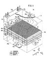
図1は、本発明の実施形態に係る燃料電池スタック10の概略斜視説明図である。
【0018】
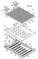
燃料電池スタック10は筐体12を備え、この筐体12内には、複数のセルユニット14が矢印A方向に積層して収容される。図2および図3に示すように、セルユニット14は、MEA(Membrane and Electrode Assembly)ユニット16と、このMEAユニット16の両面に配置される第1および第2セパレータ17a、17bとを備える。
【0019】
セルユニット14の矢印B方向の一端縁部には、積層方向である矢印A方向に連通して、燃料ガス、例えば、水素含有ガスを供給するための燃料ガス入口連通孔18aと、酸化剤ガス、例えば、酸素含有ガスを供給するための酸化剤ガス入口連通孔20aとが、矢印C方向一端側に配列して設けられる。セルユニット14の矢印B方向の一端縁部には、矢印A方向に連通して、燃料ガスを排出するための燃料ガス出口連通孔18bと、酸化剤ガスを排出するための酸化剤ガス出口連通孔20bとが、矢印C方向他端側に配列して設けられる。
【0020】
MEAユニット16は、例えば、パーフルオロスルホン酸ポリマーの薄膜である固体高分子電解質膜22を備える。この固体高分子電解質膜22を共通の電解質として、複数の電解質膜・電極構造体(発電部)24(1)〜24(n)が構成される。この電解質膜・電極構造体24(1)〜24(n)は、図2に示すように、固体高分子電解質膜22の面内に、矢印B方向および矢印C方向に所定の数ずつ配列して設けられる。
【0021】
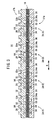
図3に示すように、固体高分子電解質膜22の両面22a、22bには、後述する電極が設けられていない部分に対応して補強用フィルム、例えば、シリコンフィルム26a、26bが設けられる。この固体高分子電解質膜22には、所定の位置に複数の孔部27が形成される(図2参照)。
【0022】
電解質膜・電極構造体24(1)は、固体高分子電解質膜22の一方の面22aに設けられるカソード側電極28と、前記固体高分子電解質膜22の他方の面22bに設けられるアノード側電極30とを備える。カソード側電極28およびアノード側電極30は、白金合金が表面に担持された多孔質カーボン粒子を固体高分子電解質膜22の面22a、22bに塗布して構成されている。カソード側電極28には、第1導電性拡散層32が設けられるとともに、アノード側電極30には、第2導電性拡散層34が設けられる。
【0023】
電解質膜・電極構造体24(2)〜24(n)は、上記の電解質膜・電極構造体24(1)と同様に構成されており、同一の構成要素には同一の参照符号を付して、その詳細な説明は省略する。
【0024】
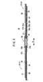
図4および図5に示すように、電解質膜・電極構造体24(1)の第1導電性拡散層32は、カソード側電極28の外周から隣接する電解質膜・電極構造体24(2)に向かって突出する第1端部32aを設ける。電解質膜・電極構造体24(2)の第2導電性拡散層34は、アノード側電極30の外周から隣接する電解質膜・電極構造体24(1)に向かって突出する第2端部34aを設ける。
【0025】
第1および第2端部32a、34aは、固体高分子電解質膜22およびシリコンフィルム26a、26bを挟んで重なり合う重合部位を有しており、この重合部位同士は、前記固体高分子電解質膜22および前記シリコンフィルム26a、26bを貫通する導電部材、例えば、導電性リベット部材36により電気的に接続される。リベット部材36は、外周面にシール材38が塗布されており、固体高分子電解質膜22の両面を気密に遮断する。このリベット部材36は、かしめ処理が施されることにより、第1および第2端部32a、34a側にフランジ部36a、36bが形成される。
【0026】
図3および図5に示すように、電解質膜・電極構造体24(2)の第1導電性拡散層32は、隣接する電解質膜・電極構造体24(3)側に向かって突出する第1端部32aを設ける。電解質膜・電極構造体24(3)の第2導電性拡散層34は、隣接する電解質膜・電極構造体24(2)側に向かって突出する第2端部34aを設ける。第1および第2端部32a、34aの重合部位同士は、リベット部材36を介して電気的に結合される。以下、電解質膜・電極構造体24(3)〜24(n)も同様にして電気的に直列に接続される。
【0027】
第1および第2セパレータ17a、17bは、非導電性の伝熱材補強プラスチック製成形体で構成される。図2および図6に示すように、第1セパレータ17aのMEAユニット16に対向する面39aには、矢印C方向一端側に矢印B方向に延在して供給マニホールド40が形成されるとともに、矢印C方向他端側に矢印B方向に延在して排出マニホールド42が形成される。供給マニホールド40は、凹部形状を有しており、燃料ガス入口連通孔18aに連通する。排出マニホールド42は、同様に凹部形状を有しており、燃料ガス出口連通孔18bに連通する。
【0028】
面39aには、供給マニホールド40から排出マニホールド42に向かって燃料ガスを供給するための燃料ガス流路44が形成される。この燃料ガス流路44は、矢印C方向に延在して供給マニホールド40と排出マニホールド42とに連通する複数本の流路溝を備えている。面39aには、電解質膜・電極構造体24(1)〜24(n)の各アノード側電極30を収容するための矩形状溝部46が形成されるとともに、所定の位置に複数のシール付きねじ孔48が形成される。
【0029】
面39aには、燃料ガス入口連通孔18a、燃料ガス出口連通孔18b、供給マニホールド40、排出マニホールド42および燃料ガス流路44を覆ってシール50が焼き付け等により設けられる。第1セパレータ17aは、−(マイナス)側の端子52が電解質膜・電極構造体24(1)のアノード側電極30に接続可能に設けられる。面39aとは反対の面39bから両側部にわたってシール部材53aが固着される。このシール部材53aは、燃料ガス入口連通孔18a、酸化剤ガス入口連通孔20a、酸化剤ガス出口連通孔20bおよび燃料ガス出口連通孔18bの近傍に設けられており、これらを筐体12内で後述する冷却媒体流路から遮断する機能を有する。
【0030】
図7に示すように、第2セパレータ17bのMEAユニット16に対向する面55aには、酸化剤ガス入口連通孔20aに連通して矢印B方向に延在する供給マニホールド54と、酸化剤ガス出口連通孔20bに連通して矢印B方向に延在する排出マニホールド56とが形成される。供給マニホールド54と排出マニホールド56とは、矢印C方向に延在する複数本の流路溝を備えた酸化剤ガス流路58を介して連通する。
【0031】
面55aには、酸化剤ガス入口連通孔20a、酸化剤ガス出口連通孔20b、供給マニホールド54、排出マニホールド56および酸化剤ガス流路58を覆ってシール59が焼き付け等により設けられる。
【0032】
面55aには、電解質膜・電極構造体24(1)〜24(n)の各カソード側電極28に対応して矩形状の溝部60が形成される。面55aには、所定の位置にシール付き孔部62が形成されており、図2に示すように、前記シール付き孔部62からMEAユニット16の孔部27を貫通して第2セパレータ17bのシール付きねじ孔48に締結ねじ64が螺合してセルユニット14が一体化される。第2セパレータ17bには、電解質膜・電極構造体24(n)のカソード側電極28に接続可能な+(プラス)側の端子66が設けられる。
【0033】
図2に示すように、第2セパレータ17bの面55aとは反対側の面55bには、矢印C方向に延在してリブ70が設けられ、前記リブ70間には、前記第2セパレータ17bの面方向に沿って冷却媒体を流すための複数のガイド溝72が形成される。
【0034】
面55bには、燃料ガス入口連通孔18a、酸化剤ガス入口連通孔20a、酸化剤ガス出口連通孔20bおよび燃料ガス出口連通孔18bに近接してシール部材53bが設けられる。このシール部材53bは、面55bから第2セパレータ17bの側面にわたって設けられる。第1および第2セパレータ17a、17bが重ね合わされた際、シール部材53a、53bによりセルユニット14を周回するシール構造が構成される。
【0035】
筐体12は、図1に示すように、アルミニウム外板樹脂で構成されており、複数のセルユニット14を積層して収容する室12a内には、各セルユニット14のガイド溝72に一体的に連通する冷却媒体供給路(冷却媒体流路)74aおよび冷却媒体排出路(冷却媒体流路)74bが設けられる。
【0036】
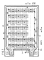
図1および図8に示すように、冷却媒体供給路74aは、筐体12の内壁面と積層される複数のセルユニット14の矢印C1方向端面との間に形成されるとともに、冷却媒体排出路74bは、前記筐体12の内壁面と前記セルユニット14の矢印C2方向端面との間に形成される。筐体12の下面には、矢印C1方向端縁部に冷却媒体供給路74aに連通して冷却媒体入口76aが形成される一方、前記筐体12の上面には、矢印C2方向端縁部に冷却媒体排出路74bに連通して冷却媒体出口76bが形成される。
【0037】
図1に示すように、複数のセルユニット14が矢印A方向に積層されることにより、各セルユニット14に設けられているシール部材53a、53bからなるシール構造が互いに積層され、筐体12内は、室12aと反応ガス室12bとに遮断される。この反応ガス室12bには、筐体カバー78が設けられる。
【0038】
図9に示すように、各セルユニット14間には、連通口連結用スペーサ80a、80bが介装される。スペーサ80aには、燃料ガス入口連通孔18aと酸化剤ガス入口連通孔20aとが形成されるとともに、スペーサ80bには、酸化剤ガス出口連通孔20bと燃料ガス出口連通孔18bとが形成される(図2参照)。
【0039】
各セルユニット14の端子52は、ターミナル締結ボルト82aにより一体的に締結される一方、端子66は、ターミナル締結ボルト82bを介して一体的に締結される。
【0040】
このように構成される燃料電池スタック10を製造する作業について、以下に説明する。
【0041】
まず、図2に示すように、第1および第2セパレータ17a、17b間にMEAユニット16が挟持された状態で、シール付き孔部62に締結ねじ64が挿入されて、この締結ねじ64の先端がシール付きねじ孔48に螺合する。これにより、第1セパレータ17a、MEAユニット16および第2セパレータ17bが一体的に締め付け固定され、セルユニット14が得られる。
【0042】
そこで、各セルユニット14同士が矢印A方向に積層されるとともに、スペーサ80a、80bが介装される。所定数のセルユニット14が積層された後、ターミナル締結ボルト82a、82bがそれぞれ端子52、66を一体的に貫通し、前記端子52同士および前記端子66同士が一体的に締結される。この積層体は、図1に示すように、筐体12内に配置されることにより、各セルユニット14のシール部材53a、53bが互いに密着し、筐体12内に室12aと反応ガス室12bとが互いに遮断されて形成される。
【0043】
室12aには、セルユニット14の積層体が収容されることにより、冷却媒体入口76aに連通する冷却媒体供給路74aと、冷却媒体出口76bに連通する冷却媒体排出路74bとが形成され、前記冷却媒体供給路74aおよび前記冷却媒体排出路74bは、各セルユニット14のガイド溝72に一体的に連通している。
【0044】
次に、上記の燃料電池スタック10の動作について説明する。
【0045】
まず、図1に示すように、筐体12内には、酸化剤ガス入口連通孔20aに酸素含有ガス等の酸化剤ガスが供給されるとともに、燃料ガス入口連通孔18aに水素含有ガス等の燃料ガスが供給される。また、冷却媒体入口76aには、冷却液である冷却媒体が供給される。
【0046】
このため、酸化剤ガスは、図7に示すように、第2セパレータ17bの面55aに形成される供給マニホールド54に一旦導入された後、酸化剤ガス流路58に供給される。酸化剤ガスは、複数の流路溝を介して矢印C方向に移動し、電解質膜・電極構造体24(1)〜24(n)の各カソード側電極28に供給される。未使用の酸化剤ガスは、排出マニホールド56から酸化剤ガス出口連通孔20bに排出される。
【0047】
一方、燃料ガスは、図6に示すように、第1セパレータ17aの面39aに形成される供給マニホールド40に導入され、この供給マニホールド40に連通する燃料ガス流路44に供給される。この燃料ガス流路44では、燃料ガスが矢印C方向に移動しながら、電解質膜・電極構造体24(1)〜24(n)の各アノード側電極30に供給される。未使用の燃料ガスは、排出マニホールド42を通って燃料ガス出口連通孔18bから排出される。
【0048】
従って、電解質膜・電極構造体24(1)〜24(n)では、各カソード側電極28に供給される酸化剤ガスと、各アノード側電極30に供給される燃料ガスとが電気化学反応により消費され、発電が行われる。これにより、端子52、66間には、全ての発電部である電解質膜・電極構造体24(1)〜24(n)が電気的に直列に接続され、所望の電圧を発生させることができる。
【0049】
この場合、本実施形態では、各セルユニット14は、MEAユニット16と、このMEAユニット16を挟持する第1および第2セパレータ17a、17bとを備えるとともに、前記第1および第2セパレータ17a、17bが電気絶縁性セパレータにより構成されている。このため、第1および第2セパレータ17a、17bを、金属製セパレータで構成するものに比べて容易かつ経済的に製作することができる。
【0050】
さらに、第2セパレータ17bに冷却媒体用のガイド溝72が設けられており、このガイド溝72を良好に電気的絶縁構造にすることが可能になる。このため、冷却媒体の絶縁性を保持する必要がないため、液絡や地絡等を確実に阻止することができる。従って、燃料電池専用冷却媒体やイオン交換器等の液絡防止装置が不要になり、冷却構造の簡素化およびコストの削減が図られるという効果が得られる。
【0051】
特に、冷却媒体として、氷点下で凍結し易い純水を用いる必要がなく、例えば、凍結防止用のアルコール等を使用することがなく、固体高分子電解質膜22に酸化等の劣化が惹起することを阻止するとともに、イオン溶出防止構造が不要になる。
【0052】
しかも、ガイド溝72は、第2セパレータ17bの面方向に沿って設けられており、前記第2セパレータ17bの表面積が有効に拡大し、冷却効率が一層向上するという利点がある。その上、隣接するセルユニット14の第1および第2セパレータ17a、17b同士を接触させた状態で、前記第1および第2セパレータ17a、17b間に冷却媒体供給用のガイド溝72が形成される。これにより、例えば、筐体12に振動等の衝撃が作用した際に、互いに接触する第1および第2セパレータ17a、17b同士が触れ止め機能を有し、前記衝撃によるセルユニット14への影響を良好に回避することが可能になる。
【0053】
さらに、本実施形態では、所定数のセルユニット14が筐体12内に積層して収容されるだけで、このセルユニット14の端面と前記筐体12の内壁面との間に、冷却媒体供給路74aおよび冷却媒体排出路74bが形成される。従って、各セルユニット14毎に個別の冷却構造を組み込んだり、各セルユニット14を個別の容器で囲ったりする必要がなく、部品点数の削減を図って燃料電池スタック10全体の小型化および簡素化が図られる。しかも、各セルユニット14を個別にかつ容易に交換することができ、取り扱い作業性が良好に向上するという効果がある。
【0054】
【発明の効果】
本発明に係る燃料電池スタックでは、電気絶縁性セパレータに冷却媒体用のガイド溝を設けることにより、このガイド溝を良好に電気的絶縁構造にすることができ、液絡や地絡等を確実に防止することが可能になる。従って、燃料電池専用冷却媒体やイオン交換器等の液絡防止装置が不要になり、冷却構造の簡素化およびコストの削減が図られるとともに、定期的なメンテナンスが不要になる。
【0055】
特に、冷却媒体として、絶縁性が高いものの氷点下で凍結し易い純水を用いる必要がない。これにより、例えば、凍結防止用のアルコール等を使用することがなく、電解質膜に酸化等の劣化が惹起することを阻止するとともに、系統部品のイオン溶出防止構造が不要になる。
【0056】
さらにまた、ガイド溝が電気絶縁性セパレータの面方向に沿って設けられており、この電気絶縁性セパレータの表面積が有効に拡大し、冷却効率が一層向上する。しかも、各セルユニット毎に個別の冷却構造を組み込んだり、各セルユニットを個別の容器で囲ったりする必要がなく、部品点数の削減を図って燃料電池スタック全体の小型化および簡素化が図られる。さらに、各セルユニットは、個別にかつ容易に交換が遂行され、取り扱い作業性が良好に向上する。
【図面の簡単な説明】
【図1】本発明の実施形態に係る燃料電池スタックの概略斜視説明図である。
【図2】セルユニットの要部分解斜視説明図である。
【図3】前記セルユニットの要部断面説明図である。
【図4】前記セルユニットを構成するMEAユニットの接続状態を示す説明図である。
【図5】前記MEAユニットの正面図である。
【図6】前記セルユニットを構成する第1セパレータの正面図である。
【図7】前記セルユニットを構成する第2セパレータの正面図である。
【図8】前記燃料電池スタックを構成する筐体内の冷却媒体供給路および冷却媒体排出路の説明図である。
【図9】積層された前記セルユニットの一部斜視説明図である。
【図10】特許文献1に係る平面形燃料電池の要部断面説明図である。
【符号の説明】
10…燃料電池スタック 12…筐体
14…セルユニット 16…MEAユニット
17a、17b…セパレータ 22…固体高分子電解質膜
24(1)〜24(n)…電解質膜・電極構造体
28…カソード側電極 30…アノード側電極
53a、53b…シール部材 72…ガイド溝
74a…冷却媒体供給路 74b…冷却媒体排出路
76a…冷却媒体入口 76b…冷却媒体出口
80a、80b…スペーサ[0001]
TECHNICAL FIELD OF THE INVENTION
The present invention relates to a fuel cell stack including a cell unit in which a plurality of power generation units sandwiching an electrolyte between an anode electrode and a cathode electrode are arranged in a plane.
[0002]
[Prior art]
Generally, a polymer electrolyte fuel cell employs an electrolyte membrane (electrolyte) composed of a polymer ion exchange membrane (cation exchange membrane). On both sides of the electrolyte membrane, an electrolyte membrane / electrode structure (power generation unit) provided with an anode electrode and a cathode electrode in which a noble metal-based electrode catalyst layer is bonded to a base material mainly composed of carbon is attached to a separator (bipolar). Plate). Usually, a predetermined number of the unit cells are used as a fuel cell stack by stacking them.
[0003]
In a fuel cell of this type, a fuel gas supplied to the anode side electrode, for example, a gas mainly containing hydrogen (hereinafter, also referred to as a hydrogen-containing gas) is obtained by ionizing hydrogen on an electrode catalyst and passing through an electrolyte. It moves to the cathode side electrode side. The electrons generated during that time are taken out to an external circuit and used as DC electric energy. Since an oxidant gas, for example, a gas mainly containing oxygen or air (hereinafter also referred to as an oxygen-containing gas) is supplied to the cathode side electrode, hydrogen ions, electrons, And oxygen react to produce water.
[0004]
By the way, another fuel cell adopts a planar fuel cell in which a plurality of unit cells are arranged in one or a plurality of rows in a plane, and the unit cells are electrically connected in series. For example, in a planar fuel cell shown in FIG. 10 (see Patent Document 1), air electrodes (cathode electrodes) 2a to 2d and fuel electrodes (anode electrodes) 3a to 3d are opposed to each other with electrolyte layers 1a to 1d interposed therebetween. A plurality of
[0005]
Specifically, the Z-shaped connecting
[0006]
[Patent Document 1]
JP-A-2002-56855 (FIG. 1)
[0007]
[Problems to be solved by the invention]
By the way, when a fuel cell is used as a vehicle fuel cell for an automobile or the like, a fuel cell usually requires 200 to 600 cells per unit from the relationship between operating voltage and current. For this reason, in
[0008]
At that time, in the fuel cell, the effect of heat generation becomes remarkable by increasing the output, and a cooling structure using liquid is required. However,
[0009]
The present invention is intended to solve this kind of problem. A plurality of power generation units are stacked in a cell unit in a planar shape to increase the output, and the power generation unit has a simple and compact configuration. An object of the present invention is to provide a fuel cell stack that can be cooled well.
[0010]
[Means for Solving the Problems]
In the fuel cell stack according to
[0011]
Then, the cell unit is provided with a pair of electrically insulating separators sandwiching the plurality of power generating units, and at least one of the electrically insulating separators is arranged along a surface direction on a surface opposite to the surface facing the power generating unit. A plurality of guide grooves for flowing a cooling medium are provided. On the other hand, a cooling medium flow path is formed in the housing to communicate integrally with the guide groove of each cell unit.
[0012]
As described above, by using the electrically insulating separator, the separator can be manufactured easily and economically as compared with the metal separator. Further, the guide groove for the cooling medium can be made to have a good electrical insulation structure, and it is not necessary to maintain the insulating property of the cooling medium, and liquid junctions and ground faults can be reliably prevented. Accordingly, a cooling medium dedicated to the fuel cell and a liquid junction prevention device such as an ion exchanger are not required, so that the cooling structure is simplified and the cost is reduced, and periodic maintenance is not required.
[0013]
In particular, it is not necessary to use pure water which has a high insulating property but easily freezes below the freezing point as a cooling medium. Thus, for example, without using alcohol or the like for preventing freezing, it is possible to prevent the electrolyte membrane from deteriorating by oxidation or the like, and it is not necessary to provide an ion elution prevention structure for system components.
[0014]
Moreover, the guide grooves are provided along the surface direction of the electrically insulating separator, and the surface area of the electrically insulating separator is effectively increased, and the cooling efficiency is further improved. In addition, a guide groove can be formed between the electrically insulating separators in a state where the electrically insulating separators of adjacent cell units are in contact with each other. For this reason, when shocks such as vibrations act on the housing, the electrically insulating separators that come into contact with each other have a touch-preventing function, and it is possible to favorably avoid the influence of the shocks on the cell unit. .
[0015]
Furthermore, there is no need to incorporate an individual cooling structure for each cell unit or to surround each cell unit with an individual container, thereby reducing the number of parts and reducing the size and simplification of the entire fuel cell stack. . In addition, each cell unit can be replaced individually and easily, and handling operability is improved satisfactorily.
[0016]
Further, in the fuel cell stack according to
[0017]
BEST MODE FOR CARRYING OUT THE INVENTION
FIG. 1 is a schematic perspective view illustrating a
[0018]
The
[0019]
A fuel gas
[0020]
The
[0021]
As shown in FIG. 3, reinforcing films, for example,
[0022]
The electrolyte membrane / electrode structure 24 (1) includes a cathode-
[0023]
The electrolyte membrane / electrode structures 24 (2) to 24 (n) have the same configuration as the above-described electrolyte membrane / electrode structure 24 (1), and the same components are denoted by the same reference numerals. Therefore, detailed description thereof is omitted.
[0024]
As shown in FIGS. 4 and 5, the first
[0025]
The first and
[0026]
As shown in FIG. 3 and FIG. 5, the first
[0027]
The first and
[0028]
A fuel
[0029]
On the
[0030]
As shown in FIG. 7, on a
[0031]
On the
[0032]
On the
[0033]
As shown in FIG. 2,
[0034]
A
[0035]
As shown in FIG. 1, the
[0036]
As shown in FIGS. 1 and 8, the cooling
[0037]
As shown in FIG. 1, by stacking a plurality of
[0038]
As shown in FIG. 9, communication
[0039]
The terminal 52 of each
[0040]
The operation of manufacturing the
[0041]
First, as shown in FIG. 2, in a state where the
[0042]
Therefore, the
[0043]
In the
[0044]
Next, the operation of the
[0045]
First, as shown in FIG. 1, an oxidizing gas such as an oxygen-containing gas is supplied to the oxidizing gas
[0046]
For this reason, the oxidizing gas is once introduced into the
[0047]
On the other hand, as shown in FIG. 6, the fuel gas is introduced into a
[0048]
Accordingly, in the electrolyte membrane / electrode structures 24 (1) to 24 (n), the oxidizing gas supplied to each
[0049]
In this case, in this embodiment, each
[0050]
Further, a
[0051]
In particular, it is not necessary to use pure water that easily freezes below the freezing point as a cooling medium. For example, without using alcohol or the like for preventing freezing, it is possible to prevent deterioration of the solid
[0052]
Moreover, the
[0053]
Furthermore, in the present embodiment, only a predetermined number of
[0054]
【The invention's effect】
In the fuel cell stack according to the present invention, by providing the electrically insulating separator with the guide groove for the cooling medium, the guide groove can be made to have a good electrical insulation structure, and liquid junctions, ground faults, and the like can be reliably prevented. Can be prevented. Accordingly, a cooling medium dedicated to the fuel cell and a liquid junction prevention device such as an ion exchanger are not required, so that the cooling structure is simplified and the cost is reduced, and periodic maintenance is not required.
[0055]
In particular, it is not necessary to use pure water which has a high insulating property but easily freezes below the freezing point as a cooling medium. Thus, for example, without using alcohol or the like for preventing freezing, it is possible to prevent the electrolyte membrane from deteriorating by oxidation or the like, and it is not necessary to provide an ion elution prevention structure for system components.
[0056]
Furthermore, the guide groove is provided along the surface direction of the electrically insulating separator, and the surface area of the electrically insulating separator is effectively increased, and the cooling efficiency is further improved. Moreover, there is no need to incorporate an individual cooling structure for each cell unit or to surround each cell unit with an individual container, and the number of parts can be reduced, and the entire fuel cell stack can be reduced in size and simplified. . Furthermore, each cell unit is easily and individually exchanged, and the handling workability is improved satisfactorily.
[Brief description of the drawings]
FIG. 1 is a schematic perspective explanatory view of a fuel cell stack according to an embodiment of the present invention.
FIG. 2 is an exploded perspective view of a main part of the cell unit.
FIG. 3 is an explanatory sectional view of a main part of the cell unit.
FIG. 4 is an explanatory diagram showing a connection state of MEA units constituting the cell unit.
FIG. 5 is a front view of the MEA unit.
FIG. 6 is a front view of a first separator constituting the cell unit.
FIG. 7 is a front view of a second separator constituting the cell unit.
FIG. 8 is an explanatory diagram of a cooling medium supply path and a cooling medium discharge path in a housing constituting the fuel cell stack.
FIG. 9 is a partial perspective explanatory view of the stacked cell units.
FIG. 10 is an explanatory sectional view of a main part of a flat fuel cell according to
[Explanation of symbols]
DESCRIPTION OF
Claims (2)
前記セルユニットを複数積層して収容する筐体を備え、
前記セルユニットは、複数の前記発電部を挟持する一対の電気絶縁性セパレータを設け、少なくとも一方の前記電気絶縁性セパレータは、前記発電部に対向する面とは反対の面に、面方向に沿って冷却媒体を流すための複数のガイド溝を設けるとともに、
前記筐体内には、各セルユニットの前記ガイド溝に一体的に連通する冷却媒体流路が形成されることを特徴とする燃料電池スタック。A plurality of power generation units sandwiching the electrolyte between the anode side electrode and the cathode side electrode, a fuel cell stack including a cell unit arranged in a plane,
A housing for housing a plurality of the cell units in a stacked manner,
The cell unit is provided with a pair of electrically insulating separators sandwiching a plurality of the power generating units, and at least one of the electrically insulating separators is arranged along a surface direction on a surface opposite to a surface facing the power generating unit. And providing a plurality of guide grooves for flowing the cooling medium
A fuel cell stack, wherein a cooling medium flow path integrally communicating with the guide groove of each cell unit is formed in the housing.
前記筐体内で前記反応ガス供給連通孔および前記反応ガス排出連通孔と前記冷却媒体流路とを遮断するためのシール部材が設けられることを特徴とする燃料電池スタック。2. The fuel cell stack according to claim 1, wherein the cell unit includes a reaction gas supply communication hole and a reaction gas discharge communication hole communicating with each other in the stacking direction.
A fuel cell stack, wherein a seal member for shutting off the reaction gas supply passage and the reaction gas discharge passage and the cooling medium passage is provided in the housing.
Priority Applications (2)
| Application Number | Priority Date | Filing Date | Title |
|---|---|---|---|
| JP2003062047A JP2004273264A (en) | 2003-03-07 | 2003-03-07 | Fuel-cell stack |
| US10/795,952 US7638219B2 (en) | 2003-03-07 | 2004-03-08 | Fuel cell without Z-like connection plates and the method producing the same |
Applications Claiming Priority (1)
| Application Number | Priority Date | Filing Date | Title |
|---|---|---|---|
| JP2003062047A JP2004273264A (en) | 2003-03-07 | 2003-03-07 | Fuel-cell stack |
Publications (1)
| Publication Number | Publication Date |
|---|---|
| JP2004273264A true JP2004273264A (en) | 2004-09-30 |
Family
ID=33124083
Family Applications (1)
| Application Number | Title | Priority Date | Filing Date |
|---|---|---|---|
| JP2003062047A Withdrawn JP2004273264A (en) | 2003-03-07 | 2003-03-07 | Fuel-cell stack |
Country Status (1)
| Country | Link |
|---|---|
| JP (1) | JP2004273264A (en) |
Cited By (6)
| Publication number | Priority date | Publication date | Assignee | Title |
|---|---|---|---|---|
| JP2005527944A (en) * | 2002-04-11 | 2005-09-15 | フラウンホッファー−ゲゼルシャフト ツァー フェーデルング デア アンゲバンテン フォルシュング エー ファー | Fuel cell system having a printed circuit board structural style |
| JP2006164942A (en) * | 2004-11-15 | 2006-06-22 | Seiko Instruments Inc | Solid polymer electrolyte fuel cell |
| JP2011119229A (en) * | 2009-12-07 | 2011-06-16 | Ind Technol Res Inst | Modularized fuel cell device and flow field plate assembly |
| US8828621B2 (en) | 2009-12-07 | 2014-09-09 | Industrial Technology Research Institute | Modularized fuel cell devices and fluid flow plate assemblies |
| US9935323B2 (en) | 2014-02-27 | 2018-04-03 | Sanyo Electric Co., Ltd. | Fuel cell module and fuel cell stack |
| JP2021061199A (en) * | 2019-10-08 | 2021-04-15 | 株式会社豊田中央研究所 | Fuel cell stack |
-
2003
- 2003-03-07 JP JP2003062047A patent/JP2004273264A/en not_active Withdrawn
Cited By (8)
| Publication number | Priority date | Publication date | Assignee | Title |
|---|---|---|---|---|
| JP2005527944A (en) * | 2002-04-11 | 2005-09-15 | フラウンホッファー−ゲゼルシャフト ツァー フェーデルング デア アンゲバンテン フォルシュング エー ファー | Fuel cell system having a printed circuit board structural style |
| JP4745611B2 (en) * | 2002-04-11 | 2011-08-10 | フラウンホッファー−ゲゼルシャフト ツァー フェーデルング デア アンゲバンテン フォルシュング エー ファー | Fuel cell system having a printed circuit board structural style |
| JP2006164942A (en) * | 2004-11-15 | 2006-06-22 | Seiko Instruments Inc | Solid polymer electrolyte fuel cell |
| JP2011119229A (en) * | 2009-12-07 | 2011-06-16 | Ind Technol Res Inst | Modularized fuel cell device and flow field plate assembly |
| US8828621B2 (en) | 2009-12-07 | 2014-09-09 | Industrial Technology Research Institute | Modularized fuel cell devices and fluid flow plate assemblies |
| US9935323B2 (en) | 2014-02-27 | 2018-04-03 | Sanyo Electric Co., Ltd. | Fuel cell module and fuel cell stack |
| JP2021061199A (en) * | 2019-10-08 | 2021-04-15 | 株式会社豊田中央研究所 | Fuel cell stack |
| JP7088154B2 (en) | 2019-10-08 | 2022-06-21 | 株式会社豊田中央研究所 | Fuel cell stack |
Similar Documents
| Publication | Publication Date | Title |
|---|---|---|
| US7309542B2 (en) | Membrane electrode assembly and fuel cell | |
| EP1403951B1 (en) | Fuel cell seals | |
| JP3920018B2 (en) | Fuel cell stack | |
| JP4231679B2 (en) | Fuel cell | |
| KR20190104548A (en) | Fuel Cell Stack with Bipolar Plate / Seal Assembly and Bipolar Plate / Seal Assembly | |
| JP4820068B2 (en) | Fuel cell stack | |
| US7846589B2 (en) | Fuel cell having separator with cell voltage terminal | |
| JP3981623B2 (en) | Fuel cell stack | |
| JP2006260916A (en) | Fuel cell | |
| JP4118123B2 (en) | Fuel cell stack | |
| JP4165876B2 (en) | Fuel cell stack | |
| JP2004207074A (en) | Fuel cell | |
| JP4174022B2 (en) | Fuel cell stack | |
| US7638219B2 (en) | Fuel cell without Z-like connection plates and the method producing the same | |
| JP2005285402A (en) | Fuel cell stack | |
| JP2004273264A (en) | Fuel-cell stack | |
| CN111989810A (en) | Fuel cell | |
| US11217807B2 (en) | Fuel cell | |
| JP4083600B2 (en) | Fuel cell | |
| JP2005243286A (en) | Fuel cell stack | |
| JP4083599B2 (en) | Fuel cell and manufacturing method thereof | |
| JP2004087318A (en) | Fuel cell | |
| JP3622682B2 (en) | Fuel cell and cell unit | |
| US11728499B2 (en) | Fuel cell | |
| CN216958101U (en) | Parallel fuel cell stack |
Legal Events
| Date | Code | Title | Description |
|---|---|---|---|
| A621 | Written request for application examination |
Free format text: JAPANESE INTERMEDIATE CODE: A621 Effective date: 20051202 |
|
| A761 | Written withdrawal of application |
Free format text: JAPANESE INTERMEDIATE CODE: A761 Effective date: 20070807 |