【0001】
【発明の属する技術分野】
本発明は建設機械の操作レバーロック作動装置に関するものであり、特に、運転席への乗降スペースを確保した操作レバーロック作動装置に関するものである。
【0002】
【従来の技術】
従来、油圧ショベルをはじめとする建設機械には、運転席への乗降を規制するゲートバーを備えたものが多く、該ゲートバーを跳ね上げてオペレータの乗降が可能な状態では、作業機や走行装置の操作レバーの操作をロックする操作レバーロック手段を備えたものが知られている。即ち、該ゲートレバーの跳ね上げによりロックバルブを切り替えて、操作レバー回路を油圧的に遮断する(例えば、特許文献1参照)。
【0003】
或いは、該ゲートレバーの跳ね上げによりロックスイッチを切り替えて、操作レバー回路を電気的に遮断する構成も知られている。
【0004】
【特許文献1】
特開平8−137567号公報(第2〜10頁、図6)
【0005】
【発明が解決しようとする課題】
従来の操作レバーロック作動装置は、ゲートレバーの跳ね上げに連動して操作レバーの操作をロックしているため、乗降側のコンソールボックス付近にロックバルブやロックスイッチ等の操作レバーロック手段を設ける必要がある。従って、装置を構成する部品点数が多くなってコスト高になるとともに、運転席への乗降スペースが十分に確保できないという不具合があった。
【0006】
そこで、操作レバーロック作動装置の構成を簡素化するとともに、運転席への乗降スペースを十分に確保するために解決すべき技術的課題が生じてくるのであり、本発明はこの課題を解決することを目的とする。
【0007】
【課題を解決するための手段】
本発明は上記目的を達成するために提案されたものであり、操作レバーの操作をロックする操作レバーロック手段を備えた建設機械に於いて、運転席のシートベルトのロック状態を検出するベルトロック検出手段を設け、該ベルトロック検出手段にてシートベルトがアンロック状態のときは前記操作レバーロック手段を作動状態にし、一方、該ベルトロック検出手段にてシートベルトがロック状態のときは前記操作レバーロック手段を非作動状態にするように構成した建設機械の操作レバーロック作動装置、
及び、上記ベルトロック検出手段は、シートベルトのロック部に設けられたベルトロックスイッチである建設機械の操作レバーロック作動装置、
及び、上記ベルトロック検出手段の検出信号に基づき、上記操作レバーロック手段の作動・非作動を切り替える制御手段を設けた建設機械の操作レバーロック作動装置、
及び、上記操作レバーロック手段はリレーを介して電気系統に接続され、上記ベルトロック検出手段の検出信号に基づき該リレーをオン若しくはオフさせて、前記操作レバーロック手段の作動・非作動を切り替えるように構成した建設機械の操作レバーロック作動装置を提供するものである。
【0008】
【発明の実施の形態】
以下、本発明の一実施の形態を図面に従って詳述する。図1は建設機械の一例として油圧ショベルのキャビン10の内部を示し、運転席11の左右両側にコンソールボックス12,13が設けられ、夫々のコンソールボックス12,13にブームやアーム等の作業用の操作レバー14,15を揺動自在に突設してある。また、乗降側のコンソールボックス12の近傍に、運転席11への乗降を規制するゲートバー16を上下回動自在に設け、オペレータは該ゲートバー16を跳ね上げて運転席11へ乗降するように形成してある。
【0009】
ここで、前記運転席11にはシートベルト17が設けられており、オペレータが運転席11に着座して作業を行う場合や機体を走行させる場合は、前記シートベルト17をオペレータの腰部に掛け回してロック部18にてロックする。該ロック部18は、右側のシートベルト17の端部に設けた金具18aと左側のシートベルト17に設けた金具18bとからなり、一方の金具18aを他方の金具18bへ挿入すると、自動的にロックされるように形成してある。
【0010】
また、該ロック部18には、シートベルト17のロック状態を検出するためのベルトロック検出手段としてベルトロックスイッチ19が設けられている。該ベルトロックスイッチ19は、前記双方の金具18a,18bが離反してシートベルト17のロック部18がアンロック状態のときはオフとなり、前記一方の金具18aを他方の金具18bへ挿入してロック部18がロック状態のときはオンとなるように形成されている。尚、運転席11の前方には左右のクローラを駆動制御するための走行用の操作レバー17,18が設けられている。
【0011】
図2は操作レバーの操作をロックする操作レバーロック手段22の一例を示し、説明の都合上、左側の操作レバー14に設けられたリモコンバルブ23ついてのみ説明する。パイロットポンプ24から吐出したパイロット油は、開閉バルブ25を介して操作レバーのリモコンバルブ23に供給されるが、ソレノイド26が励磁されていないノーマル状態では、図示したように、開閉バルブ25が閉止位置(イ)にあり、パイロットポンプ24から吐出したパイロット油が該開閉バルブ25で遮断されるため、操作レバー14を傾倒操作しても、コントロールバルブ(図示せず)へのパイロット油路27へパイロット油が導出されない。即ち、操作レバーロック手段22が作動状態となって、操作レバー14の操作がロックされる。
【0012】
一方、前記ソレノイド26が励磁されると開閉バルブ25が開放位置(ロ)に切り替わり、パイロットポンプ24から吐出したパイロット油が該開閉バルブ25を通過してリモコンバルブ23に供給され、操作レバー14の傾倒操作に応じて前記パイロット油路27へパイロット油が導出される。即ち、操作レバーロック手段22が非作動状態となって、操作レバー14の操作が可能となる。
【0013】
尚、操作レバーロック手段22は図2に示した構成に限定されず、開閉バルブを電気的に切り替えるのではなく、油圧的または機械的な動作で切り替えるように構成してもよい。また、操作レバー14自体をピンやアーム等にて機械的に固定する構成であってもよい。
【0014】
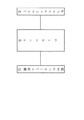
図3は操作レバーロック作動装置の動作を示すフローチャートであり、前述したベルトロック検出手段であるベルトロックスイッチ19がオフであり、シートベルト17がアンロック状態であることが検出されたときは、操作レバーロック手段22を作動状態にして操作レバー14の操作をロックする。一方、ベルトロックスイッチ19がオンであり、シートベルト17が着用されてロック状態であることが検出されたときは、操作レバーロック手段22を非作動状態にして操作レバー14の操作を可能とする。
【0015】
図4は操作レバーロック作動装置の一例を示し、前述した操作レバーロック手段22は制御手段であるコントローラ30に接続されている。また、前記シートベルトのロック部18に設けられたベルトロックスイッチ19もコントローラ30に接続されている。オペレータが運転席11に着座していない場合、或いは、シートベルト17を着用していない場合は、前記ロック部18がアンロック状態でベルトロックスイッチ19がオフであるので、コントローラ30は操作レバーロック手段22に操作ロックの指令を出力する。従って、図2に示したソレノイド26が励磁されないので前記開閉バルブ25が閉止位置(イ)にあり、操作レバーロック手段22が作動状態となって操作レバー14の操作がロックされる。
【0016】
これに対して、オペレータが運転席11に着座してシートベルト17を着用した場合は、前記ロック部18がロック状態となってベルトロックスイッチ19がオンとなり、コントローラ30は操作レバーロック手段22に操作ロック解除の指令を出力する。従って、前記ソレノイド26が励磁されて前記開閉バルブ25が開放位置(ロ)に切り替わり、操作レバーロック手段22が非作動状態となって操作レバー14の操作が可能となる。
【0017】
このように、ベルトロックスイッチ19のオン・オフ信号に基づき、操作レバーロック手段22の作動・非作動を切り替えるコントローラ30を設けた構成では、装置の構成が簡素化されてコンパクトに形成できるとともに、コントローラ30によって操作レバーロック手段22の作動・非作動の切り替えを極めて正確に制御できる。
【0018】
図5は操作レバーロック作動装置の他の一例を示し、電源のプラス側回路41に前記ベルトロックスイッチ19の一端を接続し、該ベルトロックスイッチ19の他端はレバーロック解除リレー42を介して電源のマイナス側回路43に接続する。一方、前記操作レバーロック手段22のソレノイド26は、その一端をレバーロック解除リレーのA接点44を介して電源のプラス側回路41に接続し、該ソレノイド26の他端は電源のマイナス側回路43に接続する。
【0019】
オペレータが運転席11に着座していない場合、或いは、シートベルト17を着用していない場合は、前記ロック部18がアンロック状態であるので、同図(a)に示すように、ベルトロックスイッチ19がオフとなり、レバーロック解除リレー42には通電されない。このため、レバーロック解除リレーのA接点44が開放状態であるため、前記操作レバーロック手段22のソレノイド26には通電されない。従って、図2に示したソレノイド26が励磁されないので前記開閉バルブ25が閉止位置(イ)にあり、操作レバーロック手段22が作動状態となって操作レバー14の操作がロックされる。
【0020】
これに対して、オペレータが運転席11に着座してシートベルト17を着用した場合は、前記ロック部18がロック状態であるので、同図(b)に示すように、ベルトロックスイッチ19がオンとなり、レバーロック解除リレー42に通電される。このため、レバーロック解除リレーのA接点44が閉止(接続)状態になるため、前記操作レバーロック手段22のソレノイド26に通電される。従って、図2に示したソレノイド26が励磁されて前記開閉バルブ25が開放位置(ロ)に切り替わり、操作レバーロック手段22が非作動状態となって操作レバー14の操作が可能となる。
【0021】
このように、コントローラ等の制御手段を用いずに、簡単な電気回路の構成で操作レバーロック手段22の作動・非作動を切り替えることができる。
【0022】
尚、本発明は、本発明の精神を逸脱しない限り種々の改変を為すことができ、そして、本発明が該改変されたものに及ぶことは当然である。
【0023】
【発明の効果】
本発明は上記一実施の形態に詳述したように、請求項1記載の発明は、運転席のシートベルトのロック状態をベルトロック検出手段にて検出し、シートベルトがアンロック状態のときは操作レバーロック手段を作動状態にして操作レバーの操作をロックし、シートベルトがロック状態のときは操作レバーロック手段を非作動状態にして操作レバーの操作を可能としたので、乗降側のコンソールボックス付近に部品を取り付けることなく、操作レバーロック手段の作動・非作動を切り替えることができる。従って、装置を構成する部品点数が減少してコストダウンになるとともに、運転席への乗降スペースを十分に確保することができる。
【0024】
請求項2記載の発明は、上記ベルトロック検出手段は、シートベルトのロック部に設けたベルトロックスイッチであるので、請求項1記載の発明の効果に加えて、従来の部品を流用できることから、より一層コストダウンに寄与できる。
【0025】
請求項3記載の発明は、上記ベルトロック検出手段の検出信号に基づき、操作レバーロック手段の作動・非作動を切り替える制御手段を設けたので、該制御手段によって操作レバーロック手段の作動・非作動の切り替えを極めて正確に制御できる。
【0026】
請求項4記載の発明は、上記ベルトロック検出手段の検出に基づき、リレーのオン・オフによって操作レバーロック手段の作動・非作動を切り替えるように構成したので、コントローラ等の高価な制御手段を用いずに、簡単な電気回路の構成で操作レバーロック手段の作動・非作動を切り替えることができ、安価に装置を構成することが可能である。
【図面の簡単な説明】
図は本発明の一実施の形態を示すものである。
【図1】油圧ショベルのキャビンの内部を示す斜視図。
【図2】操作レバーロック手段を示す回路図。
【図3】操作レバーロック作動装置の動作を示すフローチャート。
【図4】操作レバーロック作動装置の一例を示すブロック図。
【図5】操作レバーロック作動装置の他の一例を示し、
(a)シートベルトがアンロック状態のときの回路図。
(b)シートベルトがロック状態のときの回路図。
【符号の説明】
11 運転席
14 操作レバー
15 操作レバー
17 シートベルト
18 ロック部
19 ベルトロックスイッチ(ベルトロック検出手段)
22 操作レバーロック手段
25 開閉バルブ(操作レバーロック手段)
26 ソレノイド(操作レバーロック手段)
30 コントローラ(制御手段)
42 レバーロック解除リレー
44 レバーロック解除リレーのA接点[0001]
TECHNICAL FIELD OF THE INVENTION
The present invention relates to an operating lever lock operating device of a construction machine, and more particularly to an operating lever lock operating device that secures a space for getting on and off a driver's seat.
[0002]
[Prior art]
Conventionally, many construction machines such as hydraulic shovels are provided with a gate bar that regulates getting on and off the driver's seat. 2. Description of the Related Art There is known an operation lever provided with operation lever locking means for locking operation of an operation lever. That is, the lock valve is switched by jumping up the gate lever to hydraulically shut off the operation lever circuit (for example, see Patent Document 1).
[0003]
Alternatively, a configuration is also known in which the lock switch is switched by flipping up the gate lever to electrically cut off the operation lever circuit.
[0004]
[Patent Document 1]
JP-A-8-137567 (pages 2 to 10, FIG. 6)
[0005]
[Problems to be solved by the invention]
The conventional operation lever lock actuator locks the operation of the operation lever in conjunction with the gate lever jumping up, so it is necessary to provide an operation lever lock means such as a lock valve or a lock switch near the console box on the entrance / exit side There is. Therefore, there are problems that the number of components constituting the apparatus increases and the cost increases, and a sufficient space for getting on and off the driver's seat cannot be secured.
[0006]
Then, while simplifying the configuration of the operating lever lock operating device, there arises a technical problem to be solved in order to secure a sufficient space for getting on and off the driver's seat, and the present invention solves this problem. With the goal.
[0007]
[Means for Solving the Problems]
The present invention has been proposed to achieve the above object, and in a construction machine having an operation lever locking means for locking operation of an operation lever, a belt lock for detecting a locked state of a seat belt in a driver's seat. Detecting means for operating the operation lever locking means when the seat belt is unlocked by the belt lock detecting means, and operating the operating lever when the seat belt is locked by the belt lock detecting means. An operating lever lock operating device of a construction machine configured to make the lever lock means inoperative,
An operation lever lock operating device for a construction machine, wherein the belt lock detection unit is a belt lock switch provided in a seat belt lock unit;
And an operation lever lock operation device for a construction machine provided with control means for switching operation / non-operation of the operation lever lock means based on a detection signal of the belt lock detection means,
The operation lever lock unit is connected to an electric system via a relay, and turns on or off the relay based on a detection signal of the belt lock detection unit to switch operation / non-operation of the operation lever lock unit. The present invention provides an operating lever lock operating device for a construction machine configured as described above.
[0008]
BEST MODE FOR CARRYING OUT THE INVENTION
Hereinafter, an embodiment of the present invention will be described in detail with reference to the drawings. FIG. 1 shows the inside of a cabin 10 of a hydraulic shovel as an example of construction equipment. Console boxes 12 and 13 are provided on both left and right sides of a driver's seat 11, respectively. The operation levers 14 and 15 are provided so as to swing freely. In addition, a gate bar 16 for restricting entry / exit to the driver's seat 11 is provided in the vicinity of the console box 12 on the entry / exit side so as to be vertically rotatable. It is.
[0009]
Here, a seatbelt 17 is provided in the driver's seat 11, and when the operator sits on the driver's seat 11 to perform work or to run the aircraft, the seatbelt 17 is hung around the waist of the operator. And locked by the lock unit 18. The lock portion 18 includes a metal fitting 18a provided at an end of the right seat belt 17 and a metal fitting 18b provided on the left seat belt 17, and when one metal fitting 18a is inserted into the other metal fitting 18b, it is automatically turned on. It is formed to be locked.
[0010]
Further, the lock portion 18 is provided with a belt lock switch 19 as belt lock detection means for detecting a locked state of the seat belt 17. The belt lock switch 19 is turned off when the locks 18 of the seat belt 17 are in the unlocked state because the two metal fittings 18a and 18b are separated from each other, and the one metal fitting 18a is inserted into the other metal fitting 18b and locked. It is formed so as to be turned on when the portion 18 is in the locked state. In front of the driver's seat 11, operation levers 17 and 18 for traveling for controlling driving of the left and right crawlers are provided.
[0011]
FIG. 2 shows an example of the operation lever locking means 22 for locking the operation of the operation lever. For convenience of explanation, only the remote control valve 23 provided on the left operation lever 14 will be described. The pilot oil discharged from the pilot pump 24 is supplied to the remote control valve 23 of the operation lever via the opening / closing valve 25. In a normal state where the solenoid 26 is not excited, as shown, the opening / closing valve 25 is closed. Since the pilot oil discharged from the pilot pump 24 is shut off by the opening / closing valve 25 in (a), even if the operating lever 14 is tilted, the pilot oil flows to the pilot oil passage 27 to the control valve (not shown). No oil is delivered. That is, the operation lever lock unit 22 is activated, and the operation of the operation lever 14 is locked.
[0012]
On the other hand, when the solenoid 26 is excited, the open / close valve 25 is switched to the open position (b), and the pilot oil discharged from the pilot pump 24 passes through the open / close valve 25 and is supplied to the remote control valve 23. Pilot oil is led out to the pilot oil passage 27 according to the tilting operation. That is, the operation lever lock unit 22 is in a non-operation state, and the operation of the operation lever 14 is enabled.
[0013]
Note that the operation lever locking means 22 is not limited to the configuration shown in FIG. 2 and may be configured to switch the opening / closing valve by hydraulic or mechanical operation instead of electrically switching. Further, the configuration may be such that the operation lever 14 itself is mechanically fixed by a pin, an arm, or the like.
[0014]
FIG. 3 is a flowchart showing the operation of the operation lever lock operating device. When it is detected that the belt lock switch 19, which is the belt lock detecting means described above, is off and the seat belt 17 is in the unlocked state, The operation lever lock means 22 is set to the operating state to lock the operation of the operation lever 14. On the other hand, when the belt lock switch 19 is turned on and it is detected that the seat belt 17 is worn and the seat belt 17 is in the locked state, the operation lever locking means 22 is deactivated and the operation of the operation lever 14 is enabled. .
[0015]
FIG. 4 shows an example of the operation lever lock operating device. The above-described operation lever lock means 22 is connected to a controller 30 which is a control means. A belt lock switch 19 provided on the seat belt lock section 18 is also connected to the controller 30. When the operator is not seated on the driver's seat 11 or when the user does not wear the seat belt 17, the lock unit 18 is unlocked and the belt lock switch 19 is turned off. An operation lock command is output to the means 22. Accordingly, since the solenoid 26 shown in FIG. 2 is not excited, the opening / closing valve 25 is in the closed position (a), the operation lever locking means 22 is activated, and the operation of the operation lever 14 is locked.
[0016]
On the other hand, when the operator is seated on the driver's seat 11 and wears the seat belt 17, the lock portion 18 is locked and the belt lock switch 19 is turned on. Outputs the operation lock release command. Accordingly, the solenoid 26 is excited, the opening / closing valve 25 is switched to the open position (b), the operation lever locking means 22 is deactivated, and the operation of the operation lever 14 is enabled.
[0017]
As described above, with the configuration in which the controller 30 that switches the operation and non-operation of the operation lever lock unit 22 based on the on / off signal of the belt lock switch 19 is provided, the configuration of the device can be simplified and the device can be formed compact. Switching of the operation of the operation lever locking means 22 between the operation and the non-operation can be very accurately controlled by the controller 30.
[0018]
FIG. 5 shows another example of the operating lever lock operating device. One end of the belt lock switch 19 is connected to a positive circuit 41 of a power supply, and the other end of the belt lock switch 19 is connected via a lever lock release relay 42. Connected to the negative circuit 43 of the power supply. On the other hand, one end of the solenoid 26 of the operation lever locking means 22 is connected to the plus side circuit 41 of the power supply via the A contact 44 of the lever lock release relay, and the other end of the solenoid 26 is connected to the minus side circuit 43 of the power supply. Connect to
[0019]
When the operator is not seated on the driver's seat 11 or wearing the seat belt 17, the lock portion 18 is in an unlocked state, and therefore, as shown in FIG. 19 is turned off, and the lever lock release relay 42 is not energized. For this reason, since the A contact 44 of the lever lock release relay is open, the solenoid 26 of the operation lever locking means 22 is not energized. Accordingly, since the solenoid 26 shown in FIG. 2 is not excited, the opening / closing valve 25 is in the closed position (a), the operation lever locking means 22 is activated, and the operation of the operation lever 14 is locked.
[0020]
On the other hand, when the operator sits on the driver's seat 11 and wears the seat belt 17, the lock portion 18 is in the locked state, and the belt lock switch 19 is turned on as shown in FIG. , And the lever lock release relay 42 is energized. Therefore, the A contact 44 of the lever lock release relay is closed (connected), so that the solenoid 26 of the operation lever locking means 22 is energized. Accordingly, the solenoid 26 shown in FIG. 2 is excited, the opening / closing valve 25 is switched to the open position (b), the operation lever lock means 22 is deactivated, and the operation of the operation lever 14 becomes possible.
[0021]
As described above, the operation / non-operation of the operation lever lock unit 22 can be switched with a simple electric circuit configuration without using a control unit such as a controller.
[0022]
The present invention can be variously modified without departing from the spirit of the present invention, and it goes without saying that the present invention extends to the modified ones.
[0023]
【The invention's effect】
As described in detail in the above embodiment, the invention according to claim 1 detects the locked state of the seat belt of the driver's seat by belt lock detecting means, and when the seat belt is in the unlocked state, The operation lever locking means is activated to lock the operation of the operation lever, and when the seat belt is locked, the operation lever locking means is deactivated to enable the operation of the operation lever. It is possible to switch between operation and non-operation of the operation lever locking means without mounting any components in the vicinity. Therefore, the number of parts constituting the apparatus is reduced, which leads to cost reduction and a sufficient space for getting on and off the driver's seat.
[0024]
According to the second aspect of the present invention, since the belt lock detecting means is a belt lock switch provided in a lock portion of a seat belt, in addition to the effects of the first aspect of the present invention, conventional parts can be used. It can further contribute to cost reduction.
[0025]
According to the third aspect of the present invention, the control means for switching the operation lever lock means between operation and non-operation based on the detection signal of the belt lock detection means is provided, and the control means activates and deactivates the operation lever lock means. Switching can be controlled very accurately.
[0026]
According to the fourth aspect of the present invention, since the operation of the operation lever locking means is switched between on and off based on the detection of the belt lock detecting means, an expensive control means such as a controller is used. Instead, the operation and non-operation of the operation lever locking means can be switched with a simple electric circuit configuration, and the device can be configured at low cost.
[Brief description of the drawings]
The figure shows an embodiment of the present invention.
FIG. 1 is a perspective view showing the inside of a cabin of a hydraulic shovel.
FIG. 2 is a circuit diagram showing operation lever locking means.
FIG. 3 is a flowchart showing the operation of the operation lever lock operating device.
FIG. 4 is a block diagram showing an example of an operation lever lock operating device.
FIG. 5 shows another example of the operation lever lock operating device,
(A) The circuit diagram when the seat belt is in the unlocked state.
(B) A circuit diagram when the seat belt is in a locked state.
[Explanation of symbols]
11 Driver's seat 14 Operation lever 15 Operation lever 17 Seat belt 18 Lock section 19 Belt lock switch (belt lock detection means)
22 Operation lever locking means 25 Opening / closing valve (Operation lever locking means)
26 Solenoid (operation lever locking means)
30 controller (control means)
42 Lever lock release relay 44 A contact of lever lock release relay