JP2004268351A - Ink discharging device and re-cleaning method for ink discharging device - Google Patents
Ink discharging device and re-cleaning method for ink discharging device Download PDFInfo
- Publication number
- JP2004268351A JP2004268351A JP2003060619A JP2003060619A JP2004268351A JP 2004268351 A JP2004268351 A JP 2004268351A JP 2003060619 A JP2003060619 A JP 2003060619A JP 2003060619 A JP2003060619 A JP 2003060619A JP 2004268351 A JP2004268351 A JP 2004268351A
- Authority
- JP
- Japan
- Prior art keywords
- ink
- inkjet head
- filter
- cleaning
- filter member
- Prior art date
- Legal status (The legal status is an assumption and is not a legal conclusion. Google has not performed a legal analysis and makes no representation as to the accuracy of the status listed.)
- Pending
Links
Images


Abstract
Description
【0001】
【発明の属する技術分野】
本発明は、インク吐出装置及びインク吐出装置の再洗浄方法に関する。
【0002】
【従来の技術】
従来のインク吐出装置は、被記録媒体に対してインクを吐出させるインクジェットヘッドと、このインクジェットヘッドに供給するインクを貯留したインク容器とを別体とし、それらの間を供給チューブを含むインク供給系を介して結合した構成をとるものがある(特許文献1参照)。
【0003】
また、このようなインク吐出装置においては、インクジェットヘッドとインク供給系との間にフィルタ部材が配設されているものがある。このフィルタ部材は、微細なメッシュ状であり、インクジェットヘッドのノズルに詰まる可能性がある異物がインク供給系を介してインクジェットヘッドの内部に侵入するのを防止する。ここで、インクジェットヘッドのノズルに詰まる可能性がある異物とは、インクに含まれない固形物及び半固形物を言う。また、長期保存等により生じるインク成分の凝集物も、インクジェットヘッドのノズルに詰まる可能性があるため、異物である。
【0004】
このようなインク吐出装置のインクジェットヘッドは、その製造工程において、インクジェットヘッド内部の異物を除去すべく洗浄処理が施されている。そして、フィルタ部材は、このような洗浄処理が施されたインクジェットヘッドに配設されることになる。ここで、フィルタ部材は、インクジェットヘッドに接着剤により固定的に接着されている。このようにフィルタ部材を固定的に接着するのは、出荷後にフィルタ部材がずれてしまう等の不具合が生じた場合には異物がインクジェットヘッド内部に侵入してしまい品質問題になりかねないことから、このような事態を回避すべく、フィルタ部材をインクジェットヘッドに対して固定して取り外し不可とするためである。
【0005】
【特許文献1】
特開昭57−24283号公報
【0006】
【発明が解決しようとする課題】
ところで、上述したようなインク吐出装置は、インクジェットヘッドのノズルからインクが正しく吐出されるか否かを検査する印字検査工程を経てから出荷することになる。そして、印字検査工程においてインクの不吐出等の不具合が発生した場合には、インクジェットヘッドを再洗浄することでインクジェットヘッドの内部の異物を取り除くようにしている。
【0007】
ところが、上述したようなインク吐出装置においては、インクジェットヘッドにはフィルタ部材が接着されて固定されているために、インクジェットヘッドの再洗浄は、インクジェットヘッドに対してインク供給系を介して洗浄液を流し込み、インクジェットヘッドのノズル側から吸引装置で洗浄液を吸引する、という煩雑な手法を採らざるを得ない。このような手法によれば、フィルタ部材での圧力損失が大きく洗浄に時間がかかるとともに、インクジェットヘッドのノズル径より大きな異物は取り出せないという問題がある。
【0008】
本発明は、インクジェットヘッドからのフィルタ部材の取り外しを簡単に行うことができ、かつ、インクジェットヘッドのノズルからは除去できない大きな異物を取り除くことができるインク吐出装置を提供することを目的とする。
【0009】
【課題を解決するための手段】
本発明は、インクを貯留するインク容器から供給されたインクを複数のノズルから選択的に吐出するインクジェットヘッドを備えるインク吐出装置において、前記インク容器から前記インクジェットヘッドに対して供給されるインク中の異物をフィルタリングするフィルタを固定したフィルタ部材と、このフィルタ部材を前記インクジェットヘッドに対して着脱自在に結合する結合部材と、を備える。
【0010】
したがって、インクジェットヘッドと、このインクジェットヘッドに対して供給されるインク中の異物をフィルタリングするフィルタを有するフィルタ部材とが、結合部材により着脱自在に結合される。また、インク中の異物をフィルタリングするフィルタは、フィルタ部材において固定されている。
【0011】
【発明の実施の形態】
本発明の実施の一形態を図1ないし図8に基づいて説明する。
【0012】
[インク吐出装置の構造]
ここで、図1は本実施の形態のインク吐出装置1を概略的に示す外観斜視図、図2はその分解斜視図である。図1または図2に示すように、インク吐出装置1は、インク滴を吐出する多数のノズル2が配列されたインクジェットヘッド3を備えている。
【0013】
ここで、インクジェットヘッド3の構造について説明する。図3は、インクジェットヘッド3の構造を一部を切り欠いて示す斜視図である。図3に示すように、インクジェットヘッド3は、少なくとも一方が圧電部材よりなる下層基板11及び上層基板12とからなる積層された基板13と天板14とを接着又は接合により一体したヘッド本体15に、多数のノズル2が設けられたノズル板16を接着した構造になっている。より詳細には、基板13には、上層基板12の上面から下層基板11の内部まで到達するとともに、前面が開口し後部が閉鎖した多数の溝17が形成されており、さらに、これらの溝17の後部から基板13の上面後端まで延長して前記溝17内に形成された電極18に接続された配線パターン19が形成されている。この時、基板13に形成された溝17は、それらの溝17の両側に形成された側壁20と天板14とで一つ一つが遮断されてインク流路を兼ねたインク室21とされ、さらに、これらのインク室21のすべてに連通する共通インク供給路22が天板14の下面に形成されている。ノズル2は、このインク室21毎に開口している。
【0014】
また、図1または図2に示すように、天板14の上面には、共通インク供給路22に連通するインク供給口23が形成されている。このインク供給口23には、インク供給系30が配設され、インクを貯留するインク容器(図示せず)からこのインク供給系30を介してインク室21にインクが供給される。
【0015】
このようなインクジェットヘッド3は、図1または図2に示すように、ベース板4上にエポキシ系接着剤等により固着されている。また、インクジェットヘッド3の圧電部材を駆動する駆動回路(図示せず)を実装したドライバIC5も、ベース板4上に固着されている。これらのインクジェットヘッド3とドライバIC5とは、配線パターン6を介して接続されている。
【0016】
また、カバー7は、上述したようなベース板4上のドライバIC5と配線パターン6とを覆って保護する保護部材である。このカバー7は、ドライバIC5と配線パターン6とを覆うようにベース板4上に接着されて固定されている。
【0017】
次に、本発明の特徴的な部分であるインク供給系30について説明する。インク供給系30は、インク容器からインクジェットヘッド3にインクを供給するインク供給経路を形成するものであって、図1または図2に示すように、インク容器に接続される供給チューブ31と、この供給チューブ31が接続される樹脂製のフィルタ保持部材32と、インクジェットヘッド3のインク供給口23に差し込まれて固定的に接着されておりフィルタ保持部材32を着脱自在に支持する支持部材33と、により構成されている。フィルタ保持部材32はフィルタ部材として機能するものであって、インク中の異物をフィルタリングするためのフィルタ(図示せず)を固定している。インク中の異物とは、インクに含まれない固形物及び半固形物を言う。また、長期保存等により生じるインク成分の凝集物も、異物である。このフィルタは、例えばステンレスメッシュで形成されている。このようにインク中の異物をフィルタリングするフィルタがフィルタ保持部材32において固定されていることから、出荷後にフィルタがずれてしまう等の不具合が生じることはない。
【0018】
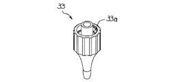
ここで、図4はフィルタ保持部材32を示す斜視図、図5は支持部材33を示す斜視図である。図4に示すように、フィルタ保持部材32は、フィルタを収納するフィルタ収納ケース32aを主体に構成されており、このフィルタ収納ケース32aの一側面には、供給チューブ31が接続されてフィルタ収納ケース32aの内部に連通する筒状のチューブ連結口32bが突出形成されている。また、フィルタ収納ケース32aの他の側面には、フィルタ収納ケース32aの内部に連通するオス型のルアーフィッティング32cが形成されている。一方、図5に示すように、支持部材33は、汎用的なルアーフィッティングであり、メス型のルアーフィッティング33aが形成されている。したがって、フィルタ保持部材32と支持部材33とは、いわゆるルアーフィッティング形式により着脱自在に結合される。すなわち、ルアーフィッティング32cとルアーフィッティング33aにより、結合部材が構成されている。本実施の形態においては、このようなルアーフィッティングを用いることにより、インクジェットヘッド3とフィルタ(フィルタ保持部材32)とを簡単に着脱することが可能になっている。
【0019】
このような構成により、インク吐出装置1においては、駆動回路の駆動により選択的に所望のインク室21の圧電部材を駆動することにより、インク室21の体積を変化させて圧力をかけることでインク室21に供給されたインクをノズル2から選択的に吐出する。
【0020】
[インク吐出装置の再洗浄方法]
次に、インク吐出装置1の印字検査工程においてインクの不吐出等の不具合が発生した場合のインク吐出装置1の再洗浄方法について説明する。このような場合には、インクジェットヘッド3を再洗浄することでインクジェットヘッド3の内部の異物を取り除くようにしている。
【0021】
図6は、インクの不吐出等の不具合が発生したインク吐出装置1の再洗浄処理工程を模式的に示す説明図である。図6に示すように、本実施の形態のインク吐出装置1の再洗浄は、以下に示す手順で実施される。
(1).インクジェットヘッド3からフィルタ(フィルタ保持部材32)を取り外す。すなわち、インクジェットヘッド3に固着されている支持部材33のルアーフィッティング33aからフィルタ保持部材32のルアーフィッティング32cを取り外す。(図6(a))
(2).インクジェットヘッド3のノズル2側の面を洗浄液に浸し、フィルタ(フィルタ保持部材32)側(インク供給)側から図示しない吸引装置で洗浄液を吸引して、インクジェットヘッド3を再洗浄する。(図6(b))
(3).再洗浄が終了したインクジェットヘッド3に対してフィルタ保持部材32を結合し、再度印字検査する。すなわち、インクジェットヘッド3に固着されている支持部材33のルアーフィッティング33aに対してフィルタ保持部材32のルアーフィッティング32cを取り付ける。(図6(c)(d))
(4).印字検査によりインク吐出装置1におけるインクの不吐出等の不具合が発生しなかった場合には、インクジェットヘッド3に固着されている支持部材33とフィルタ保持部材32とを接着剤により固定的に接着する。(図6(e))
(5).印字検査によりインク吐出装置1におけるインクの不吐出等の不具合が発生した場合には、インクジェットヘッド3を再洗浄する。
【0022】
したがって、本実施の形態のインク吐出装置1の再洗浄処理においては、インクジェットヘッド3からのフィルタ(フィルタ保持部材32)の取り外しを簡単に行うことができ、かつ、フィルタ(フィルタ保持部材32)の結合されていないインク供給側から洗浄液を吸引することで、ノズル2からは除去することができない大きな異物を取り除くことができる。
【0023】
また、出荷時には、インクジェットヘッド3に対してフィルタ(フィルタ保持部材32)を接着剤により固定的に接着するので、出荷後にフィルタ(フィルタ保持部材32)がずれてしまう等の不具合が生じることはなく、品質問題を回避することが可能になる。
【0024】
なお、本実施の形態においては、インクジェットヘッドとフィルタとの結合形態を着脱自在にするものとして、いわゆるルアーフィッティングを用いるようにしたが、これに限るものではない。例えば、フィルタ保持部材32のルアーフィッティング32cを図7に示すようなOリング32eを有する結合部材32dに変更し、インクジェットヘッド3に固着されている支持部材33のルアーフィッティング33aをOリング32eの作用による結合手段32dの圧入を受け付ける図8に示すような結合手段33bに変更するようにしても良い。すなわち、結合手段32dと結合手段33bにより、結合部材が構成されている。
【0025】
また、本実施の形態においては、インクジェットヘッドとして、インク室21の体積を変化させて圧力をかけることでインク室21に供給されたインクをノズル2から選択的に吐出するインクジェットヘッド3を適用したが、これに限るものではない。例えば、熱を利用して気泡を発生させ、その気泡の膨張による推進力でインクをノズルから吐出するインクジェットヘッドを適用するようにしても良い。
【0026】
【発明の効果】
本発明によれば、インクジェットヘッドと、このインクジェットヘッドに対して供給されるインク中の異物をフィルタリングするフィルタを固定したフィルタ部材とを、結合部材により着脱自在とすることができるので、例えば、インク吐出装置の再洗浄処理においては、インクジェットヘッドからのフィルタ部材の取り外しを簡単に行うことができ、かつ、フィルタ部材が結合されていないインク供給側から洗浄液を吸引することで、インクジェットヘッドのノズルからは除去できない大きな異物を取り除くことができる。また、インク中の異物をフィルタリングするフィルタはフィルタ部材において固定されていることから、出荷後にフィルタがずれてしまう等の不具合が生じることもない。
【図面の簡単な説明】
【図1】本発明の実施の一形態のインク吐出装置を概略的に示す外観斜視図である。
【図2】その分解斜視図である。
【図3】インクジェットヘッドの構造を一部を切り欠いて示す斜視図である。
【図4】フィルタ保持部材を示す斜視図である。
【図5】支持部材を示す斜視図である。
【図6】インクの不吐出等の不具合が発生したインク吐出装置の再洗浄処理工程を模式的に示す説明図である。
【図7】フィルタ保持部材の変形例を示す斜視図である。
【図8】支持部材の変形例を示す斜視図である。
【符号の説明】
1 インク吐出装置
2 ノズル
3 インクジェットヘッド
32 フィルタ部材
32c,33a 結合部材、ルアーフィッティング
32d,33b 結合部材[0001]
TECHNICAL FIELD OF THE INVENTION
The present invention relates to an ink ejection device and a method for re-cleaning an ink ejection device.
[0002]
[Prior art]
2. Description of the Related Art A conventional ink ejecting apparatus has an ink supply system including an ink supply head that ejects ink to a recording medium and an ink container that stores ink to be supplied to the ink jet head. (See Patent Document 1).
[0003]
In some of such ink ejection apparatuses, a filter member is provided between an inkjet head and an ink supply system. The filter member has a fine mesh shape, and prevents foreign substances that may possibly clog the nozzles of the inkjet head from entering the interior of the inkjet head via the ink supply system. Here, the foreign substance that may clog the nozzles of the inkjet head refers to solid substances and semi-solid substances not contained in the ink. In addition, aggregates of the ink components generated by long-term storage or the like are foreign matters because they may clog the nozzles of the inkjet head.
[0004]
The ink jet head of such an ink ejection apparatus is subjected to a cleaning process in a manufacturing process to remove foreign matter inside the ink jet head. Then, the filter member is disposed on the inkjet head that has been subjected to such a cleaning process. Here, the filter member is fixedly adhered to the inkjet head with an adhesive. The reason why the filter member is fixedly bonded in this way is that if a problem such as the filter member being displaced after shipment occurs, foreign matter may enter the ink jet head and cause a quality problem. This is because, in order to avoid such a situation, the filter member is fixed to the inkjet head and cannot be removed.
[0005]
[Patent Document 1]
JP-A-57-24283
[Problems to be solved by the invention]
By the way, the above-described ink ejection apparatus is shipped after a print inspection process for inspecting whether or not ink is properly ejected from nozzles of an inkjet head. Then, when a defect such as non-ejection of the ink occurs in the print inspection process, the foreign matter inside the inkjet head is removed by re-cleaning the inkjet head.
[0007]
However, in the above-described ink ejection apparatus, since the filter member is adhered and fixed to the ink jet head, the cleaning of the ink jet head is performed by pouring the cleaning liquid into the ink jet head via the ink supply system. In addition, a complicated method of sucking the cleaning liquid from the nozzle side of the inkjet head with a suction device has to be adopted. According to such a method, there is a problem that the pressure loss in the filter member is large and it takes a long time for cleaning, and a foreign substance larger than the nozzle diameter of the inkjet head cannot be taken out.
[0008]
SUMMARY OF THE INVENTION It is an object of the present invention to provide an ink ejecting apparatus which can easily remove a filter member from an ink jet head and can remove large foreign matter which cannot be removed from nozzles of the ink jet head.
[0009]
[Means for Solving the Problems]
The present invention is directed to an ink ejection apparatus including an inkjet head that selectively ejects ink supplied from an ink container that stores ink from a plurality of nozzles. A filter member to which a filter for filtering foreign matter is fixed; and a coupling member for detachably coupling the filter member to the inkjet head.
[0010]
Therefore, the inkjet head and the filter member having the filter for filtering foreign matter in the ink supplied to the inkjet head are detachably connected by the connecting member. Further, a filter for filtering foreign matter in the ink is fixed on a filter member.
[0011]
BEST MODE FOR CARRYING OUT THE INVENTION
An embodiment of the present invention will be described with reference to FIGS.
[0012]
[Structure of ink ejection device]
Here, FIG. 1 is an external perspective view schematically showing an ink ejection apparatus 1 of the present embodiment, and FIG. 2 is an exploded perspective view thereof. As shown in FIG. 1 or FIG. 2, the ink ejection device 1 includes an
[0013]
Here, the structure of the
[0014]
Further, as shown in FIG. 1 or FIG. 2, an
[0015]
Such an
[0016]
The
[0017]
Next, the
[0018]
Here, FIG. 4 is a perspective view showing the
[0019]
With such a configuration, in the ink ejection device 1, by selectively driving the piezoelectric member of the desired
[0020]
[Re-cleaning method of ink ejection device]
Next, a description will be given of a method of re-cleaning the ink discharge device 1 when a problem such as ink non-discharge occurs in the print inspection process of the ink discharge device 1. In such a case, foreign matters inside the
[0021]
FIG. 6 is an explanatory diagram schematically showing a re-cleaning process of the ink ejection device 1 in which a problem such as non-ejection of ink has occurred. As shown in FIG. 6, the re-cleaning of the ink ejection device 1 of the present embodiment is performed according to the following procedure.
(1). The filter (the filter holding member 32) is removed from the
(2). The surface of the
(3). The
(4). If no problem such as non-ejection of the ink in the ink ejection device 1 does not occur in the print inspection, the
(5). When a problem such as non-ejection of ink in the ink ejection device 1 occurs in the print inspection, the
[0022]
Therefore, in the re-cleaning process of the ink ejection device 1 according to the present embodiment, the filter (the filter holding member 32) can be easily removed from the
[0023]
Further, at the time of shipment, the filter (the filter holding member 32) is fixedly adhered to the
[0024]
In the present embodiment, a so-called luer fitting is used to make the connection between the inkjet head and the filter detachable, but the present invention is not limited to this. For example, the luer fitting 32c of the
[0025]
Further, in the present embodiment, as the inkjet head, an
[0026]
【The invention's effect】
According to the present invention, the ink jet head and a filter member to which a filter for filtering foreign matter in the ink supplied to the ink jet head is fixed can be made detachable by a connecting member. In the re-cleaning process of the ejection device, the filter member can be easily removed from the ink jet head, and the cleaning liquid is sucked from the ink supply side to which the filter member is not connected, so that the nozzles of the ink jet head can be removed. Can remove large foreign substances that cannot be removed. Further, since the filter for filtering foreign matter in the ink is fixed to the filter member, there is no problem such as the filter being displaced after shipment.
[Brief description of the drawings]
FIG. 1 is an external perspective view schematically showing an ink ejection apparatus according to an embodiment of the present invention.
FIG. 2 is an exploded perspective view thereof.
FIG. 3 is a perspective view showing the structure of the ink jet head with a part cut away.
FIG. 4 is a perspective view showing a filter holding member.
FIG. 5 is a perspective view showing a support member.
FIG. 6 is an explanatory diagram schematically showing a re-cleaning process of the ink ejection device in which a problem such as non-ejection of ink has occurred.
FIG. 7 is a perspective view showing a modification of the filter holding member.
FIG. 8 is a perspective view showing a modification of the support member.
[Explanation of symbols]
DESCRIPTION OF SYMBOLS 1 Ink ejection device 2
Claims (4)
前記インク容器から前記インクジェットヘッドに対して供給されるインク中の異物をフィルタリングするフィルタを固定したフィルタ部材と、
このフィルタ部材を前記インクジェットヘッドに対して着脱自在に結合する結合部材と、
を備えることを特徴とするインク吐出装置。In an ink ejection apparatus including an inkjet head that selectively ejects ink supplied from an ink container that stores ink from a plurality of nozzles,
A filter member fixed with a filter for filtering foreign matter in ink supplied to the inkjet head from the ink container,
A coupling member for detachably coupling the filter member to the inkjet head,
An ink ejection device comprising:
結合部材を介してインクジェットヘッドに着脱自在に取り付けられているフィルタ部材を、前記結合部材の作用により取り外す工程と、
前記インクジェットヘッドのノズル側の面を洗浄液に浸し、インク供給側から吸引装置で洗浄液を吸引して、前記インクジェットヘッドを再洗浄する工程と、
再洗浄が終了した前記インクジェットヘッドに対し、前記結合部材の作用により前記フィルタ部材を取り付ける工程と、
を備えることを特徴とするインク吐出装置の再洗浄方法。A method for re-cleaning an ink ejection device according to claim 1 or 2, wherein
Removing the filter member detachably attached to the inkjet head via the coupling member by the action of the coupling member;
A step of immersing the nozzle side surface of the inkjet head in a cleaning liquid, sucking the cleaning liquid with a suction device from the ink supply side, and re-cleaning the inkjet head,
Attaching the filter member by the action of the coupling member to the inkjet head after the re-cleaning is completed,
A method for re-cleaning an ink ejection device, comprising:
Priority Applications (1)
| Application Number | Priority Date | Filing Date | Title |
|---|---|---|---|
| JP2003060619A JP2004268351A (en) | 2003-03-06 | 2003-03-06 | Ink discharging device and re-cleaning method for ink discharging device |
Applications Claiming Priority (1)
| Application Number | Priority Date | Filing Date | Title |
|---|---|---|---|
| JP2003060619A JP2004268351A (en) | 2003-03-06 | 2003-03-06 | Ink discharging device and re-cleaning method for ink discharging device |
Publications (1)
| Publication Number | Publication Date |
|---|---|
| JP2004268351A true JP2004268351A (en) | 2004-09-30 |
Family
ID=33123099
Family Applications (1)
| Application Number | Title | Priority Date | Filing Date |
|---|---|---|---|
| JP2003060619A Pending JP2004268351A (en) | 2003-03-06 | 2003-03-06 | Ink discharging device and re-cleaning method for ink discharging device |
Country Status (1)
| Country | Link |
|---|---|
| JP (1) | JP2004268351A (en) |
Cited By (2)
| Publication number | Priority date | Publication date | Assignee | Title |
|---|---|---|---|---|
| US7914124B2 (en) | 2006-03-27 | 2011-03-29 | Seiko Epson Corporation | Liquid supplying device and liquid ejection apparatus |
| JP2021000799A (en) * | 2019-06-24 | 2021-01-07 | セイコーエプソン株式会社 | Liquid jet head, liquid jet device, flow channel structure and method for manufacturing liquid jet head |
-
2003
- 2003-03-06 JP JP2003060619A patent/JP2004268351A/en active Pending
Cited By (3)
| Publication number | Priority date | Publication date | Assignee | Title |
|---|---|---|---|---|
| US7914124B2 (en) | 2006-03-27 | 2011-03-29 | Seiko Epson Corporation | Liquid supplying device and liquid ejection apparatus |
| JP2021000799A (en) * | 2019-06-24 | 2021-01-07 | セイコーエプソン株式会社 | Liquid jet head, liquid jet device, flow channel structure and method for manufacturing liquid jet head |
| JP7287143B2 (en) | 2019-06-24 | 2023-06-06 | セイコーエプソン株式会社 | LIQUID JET HEAD, LIQUID EJECT APPARATUS, CHANNEL STRUCTURE, AND LIQUID JET HEAD MANUFACTURING METHOD |
Similar Documents
| Publication | Publication Date | Title |
|---|---|---|
| US6406137B1 (en) | Ink-jet print head and production method of ink-jet print head | |
| JP5381915B2 (en) | Ink jet recording head and ink jet recording apparatus | |
| JP2007090584A (en) | Inkjet head cleaning device | |
| US20110199432A1 (en) | Liquid Injection Head, Liquid Injection Recording Apparatus, and Method of Filling Liquid Injection Head With Liquid | |
| JP2009000961A (en) | Liquid jet recorder | |
| JP2006150937A (en) | Method and apparatus for cleaning inkjet head | |
| JP2004122463A (en) | Inkjet recording head | |
| JPH11348306A (en) | Ink jet recording apparatus | |
| JP2004268351A (en) | Ink discharging device and re-cleaning method for ink discharging device | |
| JP2003145782A (en) | Ink jet print head | |
| JP3179332B2 (en) | Cleaning method of inkjet head | |
| JP2005125653A (en) | Inkjet head, inkjet recorder, and device and method of cleaning inkjet head | |
| WO2010079654A1 (en) | Liquid jetting head, liquid jetting recording device and method for refilling liquid jetting head with liquid | |
| JP2006130682A (en) | Liquid discharge head and recording device | |
| JP7224906B2 (en) | Module substrate cleaning method | |
| US7165825B2 (en) | Process and device for cleaning an inkjet printing head | |
| JP2007090585A (en) | Inkjet head cleaning device | |
| JP4147878B2 (en) | Cleaning method for unit of ink jet recording apparatus | |
| JP2005271266A (en) | Manufacturing method and manufacturing equipment for droplet ejection head, droplet ejection head, and droplet ejector | |
| JP2007015247A (en) | Liquid jet head | |
| JP2003231276A (en) | Inkjet printer and cleaning device therefor | |
| JP4674507B2 (en) | Parts cleaning device | |
| JP2006056201A (en) | Filter and inkjet recorder with filter | |
| JP2004114648A (en) | Buffer tank for inkjet recorder and method of manufacturing the same | |
| JP2004174820A (en) | Ink jet recorder and its manufacturing process |