JP2004259941A - Casing structure of electronic device and radiation method therefor - Google Patents
Casing structure of electronic device and radiation method therefor Download PDFInfo
- Publication number
- JP2004259941A JP2004259941A JP2003049112A JP2003049112A JP2004259941A JP 2004259941 A JP2004259941 A JP 2004259941A JP 2003049112 A JP2003049112 A JP 2003049112A JP 2003049112 A JP2003049112 A JP 2003049112A JP 2004259941 A JP2004259941 A JP 2004259941A
- Authority
- JP
- Japan
- Prior art keywords
- housing
- hole
- movable fin
- heat
- electric component
- Prior art date
- Legal status (The legal status is an assumption and is not a legal conclusion. Google has not performed a legal analysis and makes no representation as to the accuracy of the status listed.)
- Granted
Links
Images


Classifications
-
- H—ELECTRICITY
- H05—ELECTRIC TECHNIQUES NOT OTHERWISE PROVIDED FOR
- H05K—PRINTED CIRCUITS; CASINGS OR CONSTRUCTIONAL DETAILS OF ELECTRIC APPARATUS; MANUFACTURE OF ASSEMBLAGES OF ELECTRICAL COMPONENTS
- H05K7/00—Constructional details common to different types of electric apparatus
- H05K7/20—Modifications to facilitate cooling, ventilating, or heating
- H05K7/2039—Modifications to facilitate cooling, ventilating, or heating characterised by the heat transfer by conduction from the heat generating element to a dissipating body
- H05K7/20409—Outer radiating structures on heat dissipating housings, e.g. fins integrated with the housing
-
- H—ELECTRICITY
- H05—ELECTRIC TECHNIQUES NOT OTHERWISE PROVIDED FOR
- H05K—PRINTED CIRCUITS; CASINGS OR CONSTRUCTIONAL DETAILS OF ELECTRIC APPARATUS; MANUFACTURE OF ASSEMBLAGES OF ELECTRICAL COMPONENTS
- H05K5/00—Casings, cabinets or drawers for electric apparatus
- H05K5/06—Hermetically-sealed casings
- H05K5/061—Hermetically-sealed casings sealed by a gasket held between a removable cover and a body, e.g. O-ring, packing
-
- H—ELECTRICITY
- H05—ELECTRIC TECHNIQUES NOT OTHERWISE PROVIDED FOR
- H05K—PRINTED CIRCUITS; CASINGS OR CONSTRUCTIONAL DETAILS OF ELECTRIC APPARATUS; MANUFACTURE OF ASSEMBLAGES OF ELECTRICAL COMPONENTS
- H05K5/00—Casings, cabinets or drawers for electric apparatus
- H05K5/06—Hermetically-sealed casings
- H05K5/068—Hermetically-sealed casings having a pressure compensation device, e.g. membrane
Abstract
Description
【0001】
【発明の属する技術分野】
本発明は、通信機器等の電子装置に関するものであり、特に密閉筐体を有する電子装置の筐体構造およびその放熱方法に関する。
【0002】
【従来の技術】
従来、通信機器等の電子装置で使用される密閉筐体では、筐体内部のパッケージ等に実装される電気回路部品からの発熱や外部環境の変化によって引き起こされる筐体内部の温度上昇を抑制して電子装置の動作の信頼性を高めるために、フィン等の放熱構造が筐体の外表面に設けられ、その放熱効果によって筐体の放熱容量は決定されている。そして、筐体の放熱容量は、筐体内部の総発熱量を上回るように設定され、その放熱構造として、密閉筐体の外表面に露出した外部ヒートシンクを有する電子装置の冷却構造がある(例えば、特許文献1参照。)。
【0003】
また、密閉筐体を有する電子装置では、筐体内部の温度が上昇すると筐体内部の気圧も高くなるので、例えば四フッ化エチレン系のメンブレンフィルタ(ゴアテックス等)を取り付け、電子装置の動作の信頼性を高めることもある。また、水の入った管を用いることにより気圧の変化を抑制して、電子装置の動作の信頼性を高めた筐体もある(例えば、特許文献2参照。)。
【0004】
【特許文献1】
特開平10−154888号公報(第3頁、図1)
【特許文献2】
特開平7−176877号公報(第2頁、図1)
【0005】
【発明が解決しようとする課題】
しかし、上述した従来の電子装置で使用される密閉筐体においては、筐体内部の気圧の変化を、例えばメンブレンフィルタを使用して調整した場合には、メンブレンフィルタを通過して外部から侵入する水蒸気や有害ガスにより筐体内部に結露が発生したり、筐体内部の電気回路部品が腐蝕したりする等の現象が起こるという問題があり、それを解決するために水の入った管を用いて調整した場合には、水が蒸発すればその効果がなくなるという問題があった。
【0006】
したがって、本発明の目的は、密閉筐体の密閉性を改善し、外部からの水蒸気や有害ガスの侵入を防止して、筐体内部の結露や電気回路部品の腐蝕等による事故を防止することができる電子装置の放熱構造およびその放熱方法であって、更に動作の信頼性を高めると同時に、更に放熱効果を高めることのできる放熱構造およびその放熱方法を提供することである。
【0007】
【課題を解決するための手段】
本発明の筐体構造は、密閉筐体の中に電気部品回路を有する電子装置の筐体構造であって、前記密閉筐体の内部温度の上昇に応じて、前記密閉筐体の外部に突出する可動フィンを有することを特徴とする。
【0008】
また、本発明の筐体構造は、密閉筐体の中に電気部品回路を有する電子装置の筐体構造であって、前記密閉筐体の上部に第1の穴、下部に第2の穴を有し、前記第1の穴及び前記第2の穴に連結された内容積が変動可能なベローズの容器とを有することを特徴とする。
【0009】
また、本発明の筐体構造は、密閉筐体の中に電気部品回路を有する電子装置の筐体構造であって、前記密閉筐体の上部に第1の穴、下部に第2の穴を有し、前記第1の穴及び前記第2の穴に連結された伸縮可能なバルーンとを有することを特徴とする。
【0010】
【発明の実施の形態】
以下,本発明の実施の形態について図面を参照して詳細に説明する。
【0011】
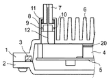
第1の実施の形態の断面図を図1、図2、図3に示す。図2および図3は、図1の7を含む部分の奥行き方向の断面図の一部を示している。本体1と蓋2は、パッキン3を介して結合され、密閉筐体を構成している。
【0012】
密閉筐体内には、電気回路部品が実装されたパッケージ4等が取り付けられた基板5が組み込まれている。
【0013】
パッケージ4は、電気回路部品が発生する熱を放熱するために、熱伝導部材20を介して、本体1の内面の一部である放熱フィン6の内面に密着して組み込まれている。
【0014】
そして、本体1にはガイド部8が備えられており、可動フィン7は、筐体内部の気圧の増減により、ガイド部8により円滑にガイドされて習動する構造となっている。
【0015】
また、筐体外部と内部とを遮断して内部の気密を保持するために、気密手段が設けられている。すなわち、可動フィン7の根元の周囲に設けられた溝9にOリング10が装着され、Oリング10によりガイド部8と可動フィン7との隙間の気密が保持される。
【0016】
更に、可動フィン7の重量と筐体内部の気圧とのバランスをとり、気圧が相対的に低くなると可動フィン7を図2の位置に復元する方向に移動させる目的で、可動フィン7とガイド部8の内面との間にバネ11が装備されている。これら可動フィン7、ガイド部8及び気密手段を備えた構成は、図1に示されるように筐体に必要な放熱容量に応じて複数設けられる。
【0017】
ガイド部8の熱を可動フィン7に効率よく伝導する目的でガイド部8と可動フィン7の間に、シリコングリス等の高熱結合部材が塗布される。そして、熱伝導効率をさらに高める目的で、パッケージ4等の発熱部分と可動フィン7との間をつなぐ高熱伝導率特性を有する可撓性シート12が備えられる。すなわち、図2に示すように、例えば、可撓性シート12は、その一端が放熱フィン6の筐体内側部分とパッケージ4との間に挟まれ、その他端が可動フィン7の中央に埋め込まれるようにして、放熱フィン6と可動フィン7との間で熱を伝導する。そして、可撓性シート12の前記両端を結ぶ部分は、可動フィン7が筐体の外側へ移動することができるように弛みを持たせて形成される。
【0018】
第1の実施の形態の動作を図1、図2、図3を使って説明する。
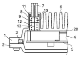
図1,2を参照すると、通信機器の稼動時には、密閉筐体内部のパッケージ4で発生した熱は、本体1の放熱フィン6の内面部分に伝わる。そして、放熱フィン6の部分に伝わった熱は、放熱フィン6の放熱作用でも放熱されるが、その一部は可撓性シート12によりガイド部8から可動フィン7に伝わり、可動フィン7と外気との熱交換作用により放熱される。本実施の形態においては、筐体の外部環境や内部発熱量の変化で、密閉筐体の内部の気圧が上昇すると、バネ11に抗して可動フィン9の筐体内部側を押し出すように働く力が強くなり、可動フィン7は筐体の外側方向に移動する。その結果、図3のように可動フィン7の表面が、大きく筐体の外に露出することになる。このようにして筐体の外気に対する放熱面積は、実質的に可動フィン7が露出した分だけ増加するので、放熱効果はその分だけ増加する。
【0019】
つまり、筐体内の発熱体から可撓性シート12に伝わる熱は可動フィン7が移動して可撓性シート12が伸びた状態(図3)においても、可動フィン7の中心に伝わって移動するので、可動フィン7による放熱作用は効率が良くなったことになる。
【0020】
逆に、図3のような高温状態から筐体内部の温度が下がると、可動フィン7の内面を押し出す圧力が弱まり、その圧力よりもバネ10の作用が強くなると、可動フィン7は図2の状態に戻る方向に移動する。このようにして、筐体内部の気圧は、バネ11とのバランス状態において、可動フィン7を移動させることにより自動的に調整される。そして、可動フィン7の移動中に、Oリング10は、外気と内部空気とを遮断するとともに、外部からの水の浸入も防止している。
【0021】
次に、本発明の第2の実施の形態を図4、図5に示す。
【0022】
本実施の形態においては、可動フィン7とガイド部8との間に設定温度において形状復帰する復帰部材13が設けられており、それ以外は前述の第1の実施の形態と同じ構成である。復帰部材13は、高温時においては、例えば図5で示されるような伸びたバネ形状に設定され、常温時においては、図4のように縮んだバネ形状をしている。
【0023】
通信機器の稼動時において、筐体内部の温度が上昇すると、復帰部材13は、前述の第1の実施の形態と同様、バネ11に抗して可動フィン7をガイド部8の外側に向けて押出すように作用しながら形状復帰し、予め設定された温度になると図5の状態になる。なお、本実施の形態においては、可動フィン7は、バネ11とともに復帰部材13の作用力のバランスにより移動することになる。
【0024】
このようにして、高温状態にあっては、可動フィン7の表面が大きく外気に露出することになるので、前述の第1の実施の形態と同様に、実質的な放熱面積が増加して、効率良く放熱が行われる。そして、可動フィン7が移動して大きくなった内部空間の分だけ、気圧を下げることができるので、その結果、高温状態における内部圧力が調整されることになる。
【0025】
なお、第2の実施の形態においては、バネ11を必ずしも設ける必要はない。この場合、筐体内部の温度変化に従って、復帰部材13の作用で可動フィン7の位置が調整されることになる。
【0026】
また、本発明の第3の実施の形態を図6により説明する。
図6において、密閉筐体の上方には、上昇した比較的温度の高い空気が通る第1の穴14が設けられるとともに、密閉筐体の下方には、第2の穴15が設けられる。この第1の穴14には内容積が変動可能なベローズ容器16の上端が連結される。第2の穴15には管17が連結され、容器16の下端には、気密および防水を保ちつつ移動可能なようにOリング18を介して管17が挿入される。
【0027】
この構成において、温度上昇に伴って気圧が上昇すると、筐体内部の比較的高い温度の空気が第1の穴14から容器16に入り、容器16は、Oリング18が管17に沿って移動する方向に膨らみ(図6に、破線で図示)、その内容積が大きくなる。その結果、密閉筐体内の気圧が調整されることになる。一方、この容器16内に流れ込んだ空気の熱は外気に放熱され、温度が下がった空気は下方に移動して、第2の穴15から筐体内へ入る。そして、筐体内の温度が下がり、気圧が下がると、容器16の内容積は小さくなる。
【0028】
更に、本発明の第4の実施の形態を図7により説明する。
図7において、前述の第3の実施の形態における容器16の代わりに第1の穴14と第2の穴15との間に伸縮可能なバルーン19を連結する。この構成において、第3の実施の形態と同様、温度上昇に伴い気圧が上昇すると、筐体内部の気圧の上昇に応じてバルーン19の内容積が大きくなり(図7に、破線で図示)、筐体内の比較的高い温度の空気は第1の穴14からバルーン19に入り、バルーン19に流れ込んだ空気の熱は外気に放熱され、第2の穴15の方向に移動し、筐体内に戻ることになる。その結果、前述の第3の実施の形態と同様、密閉筐体内の気圧は調整されることになる。そして、筐体内の温度が下がり、気圧が下がると、バルーン19は縮む。
【0029】
【発明の効果】
以上説明したように,本発明によれば、可動フィンを備え、密閉筐体の内部温度の変化に伴う気圧の変化に応じて、前記可動フィンが筐体内外に自動的に習動できるように構成したので、内部温度が上昇した場合、密閉性を保ったまま放熱面積を増やすことができ、放熱効果を上げることができる。そのため、筐体外部の有害ガスや高湿度の外気の侵入を防止することができるので、通信機器等の電子装置の信頼性を上げることができる。
【0030】
また、本発明によれば、内容積が可変するベローズ容器または伸縮可能なバルーンを備え、密閉筐体の内部温度の変化に伴う気圧の変化に応じて、前記ベローズ容器または前記バルーンの内容積が変化するので、密閉筐体の内部の気圧が調整される。そのため、筐体外部の有害ガスや高湿度の外気の侵入を防止することができるので、通信機器等の電子装置の信頼性を上げることができる。また、ベローズ容器またはバルーン内に温度が高い空気が容器に入り、その空気の熱を外気に放熱し、温度が下がった空気が筐体内に戻るので、密閉性を保ったまま放熱効果を上げることができる。
【図面の簡単な説明】
【図1】本発明の第1の実施の形態による筐体構造を示す第1の断面図である。
【図2】本発明の第1の実施の形態による筐体構造を示す第2の断面図である。
【図3】本発明の第1の実施の形態による筐体構造を示す第3の断面図である。
【図4】本発明の第2の実施の形態による筐体構造を示す第1の断面図である。
【図5】本発明の第2の実施の形態による筐体構造を示す第2の断面図である。
【図6】本発明の第3の実施の形態による筐体構造を示す断面図である。
【図7】本発明の第4の実施の形態による筐体構造を示す断面図である。
【符号の説明】
1 本体
2 蓋
3 パッキン
4 パッケージ
5 基板
6 放熱フィン
7 可動フィン
8 ガイド部
9 溝
10 Oリング
11 バネ
12 可撓性シート
13 復帰部材
14 第1の穴
15 第2の穴
16 容器
17 管
18 Oリング
19 バルーン
20 熱伝導部材[0001]
TECHNICAL FIELD OF THE INVENTION
The present invention relates to an electronic device such as a communication device, and more particularly to a housing structure of an electronic device having a closed housing and a heat dissipation method thereof.
[0002]
[Prior art]
Conventionally, in a sealed housing used for electronic devices such as communication equipment, a rise in temperature inside the housing caused by heat generated from electric circuit components mounted on a package or the like inside the housing or a change in the external environment is suppressed. In order to improve the reliability of the operation of the electronic device, a heat dissipation structure such as a fin is provided on the outer surface of the housing, and the heat dissipation capacity of the housing is determined by the heat dissipation effect. The heat dissipation capacity of the housing is set so as to exceed the total amount of heat generated inside the housing. As a heat dissipation structure, there is a cooling structure of an electronic device having an external heat sink exposed on the outer surface of the sealed housing (for example, And
[0003]
Further, in an electronic device having a closed casing, when the temperature inside the casing rises, the air pressure inside the casing also increases. For example, an ethylene tetrafluoride-based membrane filter (such as Gore-Tex) is attached, and the operation of the electronic device is performed. May increase the reliability of the system. Further, there is a case in which a change in air pressure is suppressed by using a tube containing water to improve the reliability of operation of the electronic device (for example, see Patent Document 2).
[0004]
[Patent Document 1]
JP-A-10-154888 (
[Patent Document 2]
JP-A-7-176877 (
[0005]
[Problems to be solved by the invention]
However, in the sealed housing used in the above-described conventional electronic device, when a change in the atmospheric pressure inside the housing is adjusted using, for example, a membrane filter, the air enters through the membrane filter from the outside. There is a problem that water vapor or harmful gas may cause dew condensation inside the housing, and corrosion of electric circuit components inside the housing may occur.To solve the problem, use a pipe filled with water. When the water is evaporated, the effect is lost if the water evaporates.
[0006]
Therefore, an object of the present invention is to improve the hermeticity of the hermetically sealed housing, prevent intrusion of water vapor and harmful gas from the outside, and prevent accidents due to dew condensation inside the housing and corrosion of electric circuit components. It is an object of the present invention to provide a heat dissipation structure and a heat dissipation method for an electronic device, which can further enhance the reliability of operation and further enhance the heat dissipation effect.
[0007]
[Means for Solving the Problems]
The housing structure of the present invention is a housing structure of an electronic device having an electric component circuit in a closed housing, and protrudes to the outside of the closed housing in accordance with a rise in the internal temperature of the closed housing. It is characterized by having a movable fin.
[0008]
Further, the housing structure of the present invention is a housing structure of an electronic device having an electric component circuit in a sealed housing, wherein a first hole is provided at an upper part of the sealed housing and a second hole is provided at a lower part. A bellows container having a variable inner volume connected to the first hole and the second hole.
[0009]
Further, the housing structure of the present invention is a housing structure of an electronic device having an electric component circuit in a sealed housing, wherein a first hole is provided at an upper part of the sealed housing and a second hole is provided at a lower part. And having an extendable balloon connected to the first hole and the second hole.
[0010]
BEST MODE FOR CARRYING OUT THE INVENTION
Hereinafter, embodiments of the present invention will be described in detail with reference to the drawings.
[0011]
1, 2, and 3 are cross-sectional views of the first embodiment. 2 and 3 show a part of a cross-sectional view in a depth direction of a portion including 7 in FIG. The
[0012]
A
[0013]
The
[0014]
The
[0015]
In addition, an airtight means is provided to shut off the outside and the inside of the housing and maintain the airtightness of the inside. That is, the O-
[0016]
Further, in order to balance the weight of the
[0017]
A high heat coupling member such as silicon grease is applied between the
[0018]
The operation of the first embodiment will be described with reference to FIGS.
Referring to FIGS. 1 and 2, when the communication device operates, heat generated in the
[0019]
That is, even when the
[0020]
Conversely, when the temperature inside the housing decreases from the high temperature state as shown in FIG. 3, the pressure for pushing out the inner surface of the
[0021]
Next, a second embodiment of the present invention is shown in FIGS.
[0022]
In the present embodiment, a
[0023]
When the temperature inside the housing increases during the operation of the communication device, the
[0024]
In this way, in the high temperature state, the surface of the
[0025]
In the second embodiment, the
[0026]
Further, a third embodiment of the present invention will be described with reference to FIG.
In FIG. 6, a
[0027]
In this configuration, when the air pressure rises as the temperature rises, relatively high-temperature air inside the housing enters the
[0028]
Further, a fourth embodiment of the present invention will be described with reference to FIG.
In FIG. 7, an
[0029]
【The invention's effect】
As described above, according to the present invention, a movable fin is provided so that the movable fin can be automatically moved into and out of the housing in response to a change in air pressure accompanying a change in the internal temperature of the sealed housing. With this configuration, when the internal temperature rises, the heat radiation area can be increased while maintaining the airtightness, and the heat radiation effect can be improved. Therefore, intrusion of harmful gas outside the housing or high humidity outside air can be prevented, so that the reliability of electronic devices such as communication devices can be improved.
[0030]
Further, according to the present invention, a bellows container or an expandable balloon having a variable internal volume is provided, and the internal volume of the bellows container or the balloon is changed according to a change in atmospheric pressure due to a change in the internal temperature of the closed casing. Since it changes, the air pressure inside the closed casing is adjusted. Therefore, the invasion of harmful gas or high humidity outside air outside the housing can be prevented, so that the reliability of electronic devices such as communication devices can be improved. In addition, high temperature air enters the bellows container or balloon, radiates the heat of the air to the outside air, and the cooled air returns to the housing. Can be.
[Brief description of the drawings]
FIG. 1 is a first sectional view showing a housing structure according to a first embodiment of the present invention.
FIG. 2 is a second sectional view showing the housing structure according to the first embodiment of the present invention.
FIG. 3 is a third sectional view showing the housing structure according to the first embodiment of the present invention.
FIG. 4 is a first sectional view showing a housing structure according to a second embodiment of the present invention.
FIG. 5 is a second sectional view showing a housing structure according to a second embodiment of the present invention.
FIG. 6 is a sectional view showing a housing structure according to a third embodiment of the present invention.
FIG. 7 is a sectional view showing a housing structure according to a fourth embodiment of the present invention.
[Explanation of symbols]
DESCRIPTION OF
Claims (12)
前記密閉筐体の内部温度の上昇に応じて、前記密閉筐体の外部に突出する可動フィンを有することを特徴とする筐体構造。A housing structure of an electronic device having an electric component circuit in a closed housing,
A housing structure having movable fins protruding to the outside of the sealed housing in response to a rise in the internal temperature of the sealed housing.
前記密閉筐体の上部に第1の穴、下部に第2の穴を有し、前記第1の穴及び前記第2の穴に連結された内容積が変動可能なベローズの容器とを有することを特徴とする筐体構造。A housing structure of an electronic device having an electric component circuit in a closed housing,
A closed bellows container having a first hole in an upper part and a second hole in a lower part, and a bellows container having a variable internal volume connected to the first hole and the second hole. A housing structure characterized by the following.
前記密閉筐体の上部に第1の穴、下部に第2の穴を有し、前記第1の穴及び前記第2の穴に連結された伸縮可能なバルーンとを有することを特徴とする筐体構造。A housing structure of an electronic device having an electric component circuit in a closed housing,
A housing having a first hole at an upper part of the sealed housing and a second hole at a lower part thereof, and having a telescopic balloon connected to the first hole and the second hole; Body structure.
可動フィンが、前記密閉筐体の内部温度の上昇に応じて、前記密閉筐体の外部に突出することを特徴とする放熱方法。A heat radiation method for an electronic device having an electric component circuit in a closed casing,
A heat dissipating method, wherein the movable fin projects to the outside of the closed casing according to an increase in the internal temperature of the closed casing.
前記電気部品回路が実装されたパッケージ等の熱により、前記密閉筐体の上部の第1の穴と下部の第2の穴とに連結されたベローズの容器の内容積が変動することを特徴とする放熱方法。A heat radiation method for an electronic device having an electric component circuit in a closed casing,
The internal volume of the bellows container connected to the upper first hole and the lower second hole of the closed casing fluctuates due to heat of a package or the like on which the electric component circuit is mounted. Heat dissipation method.
前記電気部品回路が実装されたパッケージ等の熱により、前記密閉筐体の上部の第1の穴と下部の第2の穴とに連結された伸縮可能なバルーンが伸縮することを特徴とする放熱方法。A heat radiation method for an electronic device having an electric component circuit in a closed casing,
The heat of a package or the like on which the electric component circuit is mounted expands and contracts an expandable balloon connected to a first hole at an upper part and a second hole at a lower part of the closed casing. Method.
Priority Applications (4)
| Application Number | Priority Date | Filing Date | Title |
|---|---|---|---|
| JP2003049112A JP4325219B2 (en) | 2003-02-26 | 2003-02-26 | Electronic device casing structure and method for adjusting the pressure inside the sealed casing |
| US10/779,770 US7161804B2 (en) | 2003-02-26 | 2004-02-18 | Housing structure of electronic device and heat radiation method therefor |
| CNB2005101343230A CN100378973C (en) | 2003-02-26 | 2004-02-25 | Housing structure of electronic device and heat radiation method therefor |
| CN200410006038.6A CN1268193C (en) | 2003-02-26 | 2004-02-25 | Housing structure of electronic device and heat radiation method therefor |
Applications Claiming Priority (1)
| Application Number | Priority Date | Filing Date | Title |
|---|---|---|---|
| JP2003049112A JP4325219B2 (en) | 2003-02-26 | 2003-02-26 | Electronic device casing structure and method for adjusting the pressure inside the sealed casing |
Publications (2)
| Publication Number | Publication Date |
|---|---|
| JP2004259941A true JP2004259941A (en) | 2004-09-16 |
| JP4325219B2 JP4325219B2 (en) | 2009-09-02 |
Family
ID=32866615
Family Applications (1)
| Application Number | Title | Priority Date | Filing Date |
|---|---|---|---|
| JP2003049112A Expired - Fee Related JP4325219B2 (en) | 2003-02-26 | 2003-02-26 | Electronic device casing structure and method for adjusting the pressure inside the sealed casing |
Country Status (3)
| Country | Link |
|---|---|
| US (1) | US7161804B2 (en) |
| JP (1) | JP4325219B2 (en) |
| CN (2) | CN100378973C (en) |
Cited By (2)
| Publication number | Priority date | Publication date | Assignee | Title |
|---|---|---|---|---|
| JP2010079404A (en) * | 2008-09-24 | 2010-04-08 | Hitachi Ltd | Electronic apparatus |
| JP2010219223A (en) * | 2009-03-16 | 2010-09-30 | Casio Hitachi Mobile Communications Co Ltd | Waterproof housing heat exhaust structure and electronic equipment |
Families Citing this family (34)
| Publication number | Priority date | Publication date | Assignee | Title |
|---|---|---|---|---|
| US20050207121A1 (en) * | 2003-06-12 | 2005-09-22 | Matsuxhita Electric Industrial Co., Ltd. | Base station device |
| GB2432460B8 (en) * | 2005-11-17 | 2010-08-18 | Iceotope Ltd | Computer apparatus |
| US8234740B2 (en) * | 2007-01-21 | 2012-08-07 | Yefim Kereth | Moisture barrier breathing device |
| US20090268394A1 (en) * | 2008-04-29 | 2009-10-29 | King Young Technology Co., Ltd. | Heat-radiating microcomputer case |
| TWM351389U (en) * | 2008-09-01 | 2009-02-21 | Aopen Inc | Computer enclosure and computer |
| GB2466966A (en) * | 2009-01-16 | 2010-07-21 | Vml Technologies Bv | Electrical housing including a pressure equalizing device |
| CN102405693A (en) * | 2009-03-25 | 2012-04-04 | 惠普开发有限公司 | Grid heat sink |
| EP2299582B1 (en) * | 2009-09-18 | 2015-03-11 | SMA Solar Technology AG | Inverter with a housing and electric and electronic components assembled within same |
| CN102123575B (en) * | 2010-01-12 | 2012-10-24 | 纬创资通股份有限公司 | Heat radiation module and portable electronic device provided with same |
| US8537540B2 (en) * | 2010-11-02 | 2013-09-17 | Technology Advancement Group, Inc. | Field serviceable CPU module |
| TWM413319U (en) * | 2011-05-13 | 2011-10-01 | Askey Computer Corp | Heat-dissipating casing for communication apparatus |
| CN102810174B (en) * | 2011-06-02 | 2017-06-09 | 刘智佳 | A kind of guard shield of RFID label tag |
| WO2013133740A1 (en) * | 2012-03-07 | 2013-09-12 | Autoliv Development Ab | A heat exchanger arrangement for a vehicle and a method for providing adaptive heat dissipation for a vehicle |
| US9368870B2 (en) | 2014-03-17 | 2016-06-14 | Ubiquiti Networks, Inc. | Methods of operating an access point using a plurality of directional beams |
| JP6117737B2 (en) * | 2014-05-16 | 2017-04-19 | ファナック株式会社 | Motor drive device having a housing in which an opening is formed |
| US10164332B2 (en) | 2014-10-14 | 2018-12-25 | Ubiquiti Networks, Inc. | Multi-sector antennas |
| US10284268B2 (en) * | 2015-02-23 | 2019-05-07 | Ubiquiti Networks, Inc. | Radio apparatuses for long-range communication of radio-frequency information |
| US9761954B2 (en) | 2015-10-09 | 2017-09-12 | Ubiquiti Networks, Inc. | Synchronized multiple-radio antenna systems and methods |
| CN108401403B (en) * | 2016-03-28 | 2021-07-16 | 联想(北京)有限公司 | Electronic equipment and heat dissipation method thereof |
| US9735083B1 (en) | 2016-04-18 | 2017-08-15 | International Business Machines Corporation | Adjustable heat sink fin spacing |
| US10875226B2 (en) | 2016-07-20 | 2020-12-29 | Synventive Molding Soliutions, Inc. | Injection molding apparatus and method for automatic cycle to cycle cavity injection |
| TWM541686U (en) * | 2016-12-27 | 2017-05-11 | Micro-Star Int'l Co Ltd | Electronic device |
| CN107017935A (en) * | 2017-06-19 | 2017-08-04 | 合肥赛度电子科技有限公司 | A kind of communication relays heat-dissipating casing |
| CN107240324A (en) * | 2017-07-07 | 2017-10-10 | 安徽伟合电子科技有限公司 | A kind of dummy emulation system switch board with convertible heat abstractor |
| CN107791263A (en) * | 2017-11-15 | 2018-03-13 | 纳博特南京科技有限公司 | A kind of industrial robot controller bottom plate |
| CN108667987B (en) * | 2018-05-18 | 2020-06-19 | 常州信息职业技术学院 | Flexible communication device |
| CN110337226A (en) * | 2019-08-07 | 2019-10-15 | 佛山闽雄机电科技有限公司 | It is a kind of can isolation radiating electromagnetic heater power supply |
| CN110881257A (en) * | 2019-12-10 | 2020-03-13 | 宁德师范学院 | Waterproof device can be dismantled at boats and ships communication terminal |
| CN111720780B (en) * | 2020-07-05 | 2021-12-07 | 山东九顶山光电科技有限公司 | High heat dissipation canned type LED street lamp |
| CN111988940A (en) * | 2020-08-27 | 2020-11-24 | 南京市儿童医院 | CVP pressure sensor protection device |
| CN112292007A (en) * | 2020-11-02 | 2021-01-29 | 阳光电源股份有限公司 | Water-cooling heat dissipation device and electrical apparatus |
| CN214412924U (en) * | 2020-11-20 | 2021-10-15 | 京东方科技集团股份有限公司 | Network adapter and terminal equipment |
| CN115013772B (en) * | 2022-06-09 | 2024-03-22 | 中山良遇照明科技有限公司 | Integrated high-efficiency heat dissipation solar lamp and application method thereof |
| CN117750739A (en) * | 2024-02-20 | 2024-03-22 | 山东艾琳智能科技有限公司 | Immersion server cooling system |
Family Cites Families (9)
| Publication number | Priority date | Publication date | Assignee | Title |
|---|---|---|---|---|
| DE7704459U1 (en) * | 1977-02-15 | 1977-06-02 | Ellenberger & Poensgen Gmbh, 8503 Altdorf | Push-button operated bimetal controlled overcurrent switch with trip-free release |
| US4233645A (en) * | 1978-10-02 | 1980-11-11 | International Business Machines Corporation | Semiconductor package with improved conduction cooling structure |
| US5305184A (en) * | 1992-12-16 | 1994-04-19 | Ibm Corporation | Method and apparatus for immersion cooling or an electronic board |
| JPH07176877A (en) | 1993-12-21 | 1995-07-14 | Nec Corp | Waterproof type outdoor cabinet |
| JP2885736B2 (en) | 1996-11-22 | 1999-04-26 | 宮城日本電気株式会社 | Electronic device cooling structure |
| EP0948248A1 (en) * | 1998-03-24 | 1999-10-06 | Lucent Technologies Inc. | Electronic apparatus having an environmentally sealed enclosure |
| JP4142227B2 (en) * | 2000-01-28 | 2008-09-03 | サンデン株式会社 | Inverter device for motor drive of electric compressor for vehicle |
| CN2458584Y (en) * | 2000-12-21 | 2001-11-07 | 赖吉林 | Automatic heat exchanger |
| JP2003060371A (en) * | 2001-08-16 | 2003-02-28 | Nec Corp | Radiating structure of communication apparatus cabinet |
-
2003
- 2003-02-26 JP JP2003049112A patent/JP4325219B2/en not_active Expired - Fee Related
-
2004
- 2004-02-18 US US10/779,770 patent/US7161804B2/en not_active Expired - Fee Related
- 2004-02-25 CN CNB2005101343230A patent/CN100378973C/en not_active Expired - Fee Related
- 2004-02-25 CN CN200410006038.6A patent/CN1268193C/en not_active Expired - Fee Related
Cited By (2)
| Publication number | Priority date | Publication date | Assignee | Title |
|---|---|---|---|---|
| JP2010079404A (en) * | 2008-09-24 | 2010-04-08 | Hitachi Ltd | Electronic apparatus |
| JP2010219223A (en) * | 2009-03-16 | 2010-09-30 | Casio Hitachi Mobile Communications Co Ltd | Waterproof housing heat exhaust structure and electronic equipment |
Also Published As
| Publication number | Publication date |
|---|---|
| CN1268193C (en) | 2006-08-02 |
| CN100378973C (en) | 2008-04-02 |
| CN1797751A (en) | 2006-07-05 |
| US7161804B2 (en) | 2007-01-09 |
| JP4325219B2 (en) | 2009-09-02 |
| US20040165352A1 (en) | 2004-08-26 |
| CN1543304A (en) | 2004-11-03 |
Similar Documents
| Publication | Publication Date | Title |
|---|---|---|
| JP2004259941A (en) | Casing structure of electronic device and radiation method therefor | |
| KR102334791B1 (en) | Thermal management with variable conductance heat pipe | |
| MXPA03006187A (en) | An electronic device. | |
| EP1701604A1 (en) | Electronic device with a waterproof heat-dissipating structure | |
| JP2012099612A (en) | Semiconductor device | |
| US20030021310A1 (en) | Method and apparatus for cooling electronic or opto-electronic devices | |
| JPH11351769A (en) | Heat sink | |
| JP6888177B1 (en) | Mechanical deformation cooling device using phase change | |
| JP2017201739A (en) | Electronic device | |
| JPH11261265A (en) | Radiation structure of sealed device | |
| JP2006339223A (en) | Heat dissipation structure of cpu | |
| JP2001068880A (en) | Cooling structure of communication equipment | |
| JP6361315B2 (en) | Cold plate | |
| JP2003188327A (en) | Heat dissipating module | |
| CN115883705A (en) | Mobile phone shell with thermal ground plane | |
| JP6701701B2 (en) | Inverter device | |
| JP2009216343A (en) | Heat transfer hinge device and cooling apparatus | |
| JP2007115965A (en) | Electronic apparatus | |
| TWI760406B (en) | A computer circuit board cooling arrangement | |
| JP2012004493A (en) | Electronic equipment device | |
| JP2008130715A (en) | Heatsink, and power converting device using it | |
| JP2007274565A (en) | Imaging apparatus | |
| JP2003086976A (en) | Heat radiation structure of electronic equipment | |
| JP2005251916A (en) | Cooling structure of electronic apparatus case | |
| JP2005300092A (en) | Storage device for refrigerator control board |
Legal Events
| Date | Code | Title | Description |
|---|---|---|---|
| RD01 | Notification of change of attorney |
Free format text: JAPANESE INTERMEDIATE CODE: A7421 Effective date: 20050310 |
|
| A621 | Written request for application examination |
Free format text: JAPANESE INTERMEDIATE CODE: A621 Effective date: 20060113 |
|
| RD01 | Notification of change of attorney |
Free format text: JAPANESE INTERMEDIATE CODE: A7421 Effective date: 20070118 |
|
| A977 | Report on retrieval |
Free format text: JAPANESE INTERMEDIATE CODE: A971007 Effective date: 20080527 |
|
| A131 | Notification of reasons for refusal |
Free format text: JAPANESE INTERMEDIATE CODE: A131 Effective date: 20080610 |
|
| RD01 | Notification of change of attorney |
Free format text: JAPANESE INTERMEDIATE CODE: A7421 Effective date: 20080610 |
|
| A521 | Written amendment |
Free format text: JAPANESE INTERMEDIATE CODE: A523 Effective date: 20080801 |
|
| A02 | Decision of refusal |
Free format text: JAPANESE INTERMEDIATE CODE: A02 Effective date: 20080930 |
|
| A521 | Written amendment |
Free format text: JAPANESE INTERMEDIATE CODE: A523 Effective date: 20081127 |
|
| A911 | Transfer to examiner for re-examination before appeal (zenchi) |
Free format text: JAPANESE INTERMEDIATE CODE: A911 Effective date: 20090108 |
|
| A131 | Notification of reasons for refusal |
Free format text: JAPANESE INTERMEDIATE CODE: A131 Effective date: 20090217 |
|
| A521 | Written amendment |
Free format text: JAPANESE INTERMEDIATE CODE: A523 Effective date: 20090415 |
|
| TRDD | Decision of grant or rejection written | ||
| RD01 | Notification of change of attorney |
Free format text: JAPANESE INTERMEDIATE CODE: A7421 Effective date: 20090508 |
|
| A01 | Written decision to grant a patent or to grant a registration (utility model) |
Free format text: JAPANESE INTERMEDIATE CODE: A01 Effective date: 20090519 |
|
| A01 | Written decision to grant a patent or to grant a registration (utility model) |
Free format text: JAPANESE INTERMEDIATE CODE: A01 |
|
| A61 | First payment of annual fees (during grant procedure) |
Free format text: JAPANESE INTERMEDIATE CODE: A61 Effective date: 20090601 |
|
| FPAY | Renewal fee payment (event date is renewal date of database) |
Free format text: PAYMENT UNTIL: 20120619 Year of fee payment: 3 |
|
| R150 | Certificate of patent or registration of utility model |
Free format text: JAPANESE INTERMEDIATE CODE: R150 |
|
| LAPS | Cancellation because of no payment of annual fees |