JP2004255700A - Process for creating dot data while saving memory capacity - Google Patents
Process for creating dot data while saving memory capacity Download PDFInfo
- Publication number
- JP2004255700A JP2004255700A JP2003048823A JP2003048823A JP2004255700A JP 2004255700 A JP2004255700 A JP 2004255700A JP 2003048823 A JP2003048823 A JP 2003048823A JP 2003048823 A JP2003048823 A JP 2003048823A JP 2004255700 A JP2004255700 A JP 2004255700A
- Authority
- JP
- Japan
- Prior art keywords
- buffer
- image data
- color image
- color
- Prior art date
- Legal status (The legal status is an assumption and is not a legal conclusion. Google has not performed a legal analysis and makes no representation as to the accuracy of the status listed.)
- Withdrawn
Links
Images


Classifications
-
- H—ELECTRICITY
- H04—ELECTRIC COMMUNICATION TECHNIQUE
- H04N—PICTORIAL COMMUNICATION, e.g. TELEVISION
- H04N1/00—Scanning, transmission or reproduction of documents or the like, e.g. facsimile transmission; Details thereof
- H04N1/40—Picture signal circuits
-
- H—ELECTRICITY
- H04—ELECTRIC COMMUNICATION TECHNIQUE
- H04N—PICTORIAL COMMUNICATION, e.g. TELEVISION
- H04N1/00—Scanning, transmission or reproduction of documents or the like, e.g. facsimile transmission; Details thereof
- H04N1/40—Picture signal circuits
- H04N1/405—Halftoning, i.e. converting the picture signal of a continuous-tone original into a corresponding signal showing only two levels
-
- H—ELECTRICITY
- H04—ELECTRIC COMMUNICATION TECHNIQUE
- H04N—PICTORIAL COMMUNICATION, e.g. TELEVISION
- H04N1/00—Scanning, transmission or reproduction of documents or the like, e.g. facsimile transmission; Details thereof
- H04N1/46—Colour picture communication systems
- H04N1/52—Circuits or arrangements for halftone screening
Landscapes
- Engineering & Computer Science (AREA)
- Multimedia (AREA)
- Signal Processing (AREA)
- Ink Jet (AREA)
- Record Information Processing For Printing (AREA)
- Color, Gradation (AREA)
Abstract
Description
【0001】
【発明の属する技術分野】
本発明は、主走査を行いつつ印刷ヘッドのノズルからインクを吐出させてカラー印刷を行う技術に関する。
【0002】
【従来の技術】
インクジェットプリンタはコンピュータの出力装置として普及している。近年では、高画質化のためにインクジェットプリンタの印刷解像度が高まる傾向にあり、また、高速化のために1色当たりのノズル数も増大する傾向にある。
【0003】
【発明が解決しようとする課題】
インクジェットプリンタで印刷を行う際には、RGBデータなどのカラー画像データから、各インクのインクドットの記録状態を表すドットデータを作成する処理が実行される。この処理では、多量のバッファメモリが使用されるが、印刷解像度やノズル数の増大に伴って、バッファメモリの必要容量も大幅に上昇する。例えば、印刷解像度が主走査方向と副走査方向にそれぞれ2倍になれば、印刷領域の画素数は4倍になる。このとき、単純な計算では、バッファメモリの容量も4倍となる。また、印刷解像度が4倍になればバッファメモリの容量は16倍にも達する。
【0004】
しかし、バッファメモリとして利用可能なメモリ資源には限界がある。そこで、従来から、ドットデータ作成処理時に必要とされるバッファメモリの容量を削減したいという要望があった。
【0005】
本発明は、上記の課題を解決するためになされたものであり、ドットデータ作成処理時に必要とされるバッファメモリの容量を削減できる技術を提供することを目的とする。
【0006】
【課題を解決するための手段およびその作用・効果】
上述の課題の少なくとも一部を解決するため、本発明の方法は、主走査を行いつつ印刷ヘッドのノズルからインクを吐出させ、インクドットを印刷媒体上に記録することによってカラー印刷を行うために、インクドットの記録状態を示すドットデータを作成する方法であって、
(a)複数種類のインクを吐出するための複数のノズル群であって、副走査方向に沿ったノズルピッチが印刷画素のピッチよりも粗い複数のノズルでそれぞれ構成された複数のノズル群を備えた印刷ヘッドを準備する工程と、
(b)印刷解像度よりも粗い解像度を有するカラー画像データを準備するとともに、カラー印刷時に使用される複数のノズル全体の副走査方向の高さに相当する領域のカラー画像データを、第1のバッファに格納する工程と、
(c)1回の主走査において前記複数のノズル群によってインクドットの記録対象となる複数の印刷対象ライン上のカラー画像を表すカラー画像データを、前記第1のバッファから選択する工程と、
(d)前記選択された複数の印刷対象ライン上のカラー画像データに関して、印刷解像度を有する閾値パターンを用いたハーフトーン処理を少なくとも行うことによって、前記選択された印刷対象ライン上の印刷画素におけるインクドットの記録状態を示すドットデータを作成して第2のバッファに格納する工程と、
(e)前記第2のバッファから前記ドットデータを出力する工程と、
を備える。
【0007】
この方法によれば、第1のバッファに格納されるカラー画像データは、印刷解像度よりも粗い解像度を有するカラー画像データであって、カラー印刷時に使用される複数のノズル全体の副走査方向の高さに相当する領域の分のデータである。従って、印刷解像度が増加しても、バッファメモリの容量が過度に増大することが無いという効果がある。
【0008】
なお、前記第1のバッファに格納される前記カラー画像データは、3つの色成分で任意の色を表現する第1の表色系によって表現されており、
前記工程(d)は、前記ハーフトーン処理の前に、前記第1の表色系から前記複数種類のインクで任意の色を表現する第2の表色系に変換する工程を含むものとしてもよい。
【0009】
また、前記1回の主走査においてインクドットの記録対象となる各印刷対象ライン上の印刷画素位置が、当該主走査においてインクドットの記録対象となる記録対象画素位置と、インクドットの記録対象とならない非記録対象画素位置とを含んでいるときに、
前記工程(d)は、各印刷対象ライン上のドットデータの中で前記非記録対象画素位置におけるドットデータの値を、ドットの非形成を表す値に置き換える工程を含むものとしてもよい。
【0010】
本発明は、上述のドットデータ作成方法の他に種々の態様で実現可能であり、例えば、印刷方法および印刷装置、印刷制御方法および印刷制御装置、印刷装置とコンピュータとを備えた印刷システム、これらの方法または装置を実現するコンピュータプログラム、および、そのプログラムを記録した記録媒体など種々の態様で実現することが可能である。
【0011】
【発明の実施の形態】
以下、本発明の実施の形態について、実施例に基づき以下の順序で説明する。
A.印刷システムの概要:
B.比較例の処理:
C.実施例の処理:
D.変形例:
【0012】
A.印刷システムの概要:
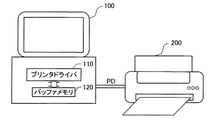
図1は、本発明の実施例としての印刷システムの構成を示すブロック図である。この印刷システムは、コンピュータ100とプリンタ200とが相互に接続された構成を有している。コンピュータ100にはプリンタドライバ110がインストールされている。プリンタドライバ110は、アプリケーションプログラム(図示せず)から画像データを受け取り、バッファメモリ120を利用して色変換処理やハーフトーン処理を行って印刷データPDを生成し、プリンタ200に供給する。印刷データPDは、印刷解像度を有する主走査ライン上の各画素についてインクドットの記録状態を指定するドットデータと、副走査送り量を特定する副走査送り量データとを含んでいる。なお、プリンタドライバ110は、印刷用のドットデータを生成する機能を実現するためのコンピュータプログラムに相当する。
【0013】
プリンタドライバ110の機能を実現するためのプログラムは、コンピュータ読み取り可能な記録媒体に記録された形態で供給し得る。このような記録媒体としては、フレキシブルディスクやCD−ROM、光磁気ディスク、ICカード、ROMカートリッジ、パンチカード、バーコードなどの符号が印刷された印刷物等のコンピュータが読み取り可能な種々の媒体を利用できる。
【0014】
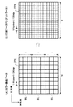
図2は、プリンタドライバ110が受け取るカラー画像データの解像度Rdataと、印刷データ(ドットデータ)の解像度Rprintとの関係を示す説明図である。本実施例では、カラー画像データの解像度Rdata(「画像データ解像度」と呼ぶ)は360dpiであり、印刷データPDの解像度Rprint(「印刷解像度」と呼ぶ)は720dpiであるものとしている。換言すれば、カラー画像データの1画素DPXのピッチは1/360インチであり、印刷画素PPXのピッチは1/720インチである。印刷解像度Rprintは、画像データ解像度Rdataよりも細かい値に設定されることが多い。なお、図3の例では主走査方向の印刷解像度と副走査方向の印刷解像度が同一であるとしているが、これらを異なる値に設定することも可能である。
【0015】
プリンタドライバ110が実行するドットデータ作成処理では、カラー画像データが、所定の大きさのバンドBLを単位として処理される。このバンドBLの主走査方向の幅Wは印刷領域の幅と同じであり、また、副走査方向の高さL(ライン数)は予め設定された値である。以下の説明では、バンドBLの主走査方向の幅Wが8インチであり、また、副走査方向の高さLが100ライン分であるものとして説明する。
【0016】
図3は、プリンタ200の印刷ヘッド210の底面におけるノズル配列を示す説明図である。この印刷ヘッド210には、7つのノズル群が設けられている。7つのノズル群は、ブラックKと、シアンCと、マゼンタMと、イエローYと、ライトシアンLCと、ライトマゼンタLMと、ダークイエローDYと、の7種類のインクを吐出するためのものである。ライトシアンLCは、シアンCと色相が同一で濃度が薄いインクである。ライトマゼンタLMも同様である。ダークイエローDYは、イエローYに若干のグレー成分が含まれているインクである。各ノズル群は、同一のノズル数を有しており、副走査方向に沿って一定のノズルピッチPnozzleで配列されている。本明細書では、ノズルピッチPnozzleの逆数Rnozzleを「ノズル解像度」と呼ぶ。図3の例では、ノズル解像度Rnozzleは180dpiである。ノズル解像度Rnozzleは、印刷解像度Rprintよりも粗い値に設定されていることが多い。
【0017】
なお、一部のノズル群(例えばブラックノズル群)は、他のノズル群よりも多くのノズルを有していてもよく、また、他のノズル群のノズルピッチの整数分の1のより小さいノズルピッチを有していてもよい。このような場合にも、カラー画像の印刷の際には、各ノズル群に関して同一数のノズルが選択されて使用されるのが普通である。印刷ヘッド210としては、一般に、複数種類のインクを吐出する複数のノズル群を有するものを用いることが可能である。
【0018】
図4は、印刷ヘッド210を用いて実行される記録方式(印刷方式)の一例を示す説明図である。図4の左側には、5回の主走査(「パス」と呼ぶ)における印刷ヘッド210の位置を示している。この図では、図示の便宜上、印刷ヘッド210は1種類のインクのための1列のノズル群で代表されており、また、そのノズル数Nnも10個であるとして簡略化されている。図4の右半分には、印刷媒体上において記録対象となる印刷画素の位置を示している。個々の小さい四角枠が印刷画素を表している。黒丸が付された画素位置(奇数画素位置)と、白丸が付された画素位置(偶数画素位置)は、互いに異なるパスにおいてドット記録の対象となることを意味している。これについては後述する。
【0019】
この例では、1パスが終了するたびに、一定の送り量F(=5ドット)の副走査が行われている。通常の副走査では印刷媒体が移動するが、図4では図示の便宜上、印刷ヘッド210が移動するものとして描かれている。副走査が行われると、ノズルの位置が順次副走査方向に移動する。なお、記録方式によっては、副走査毎に異なる送り量Fが使用される場合もある。
【0020】
パス1では、印刷ヘッド210の10個のノズルによって10本の主走査ラインL1,L5,L9…L37が走査される。従って、これらの10本の主走査ラインL1,L5,L9…L37が、インクドットの記録対象となる。また、これらの主走査ラインL1,L5,L9…L37上の画素のうち、黒丸が付された画素位置が、インクドットの記録対象となる画素位置(記録対象画素位置)である。同じ主走査ラインL1,L5,L9…L37上で白丸が付された画素位置は、パス1においてインクドットの記録対象とならない画素位置(非記録対象画素位置)である。例えば、ラインL21においては、黒丸の画素位置はパス1においてインクドットの記録対象となり、白丸の画素位置はパス5においてインクドットの記録対象となる。また、主走査ラインL1〜L20の白丸の画素位置は、図4のパス1よりも前のパスにおいてインクドットの記録対象となっている。
【0021】
本明細書では、図4のようなドット記録方式を「オーバーラップ記録方式」と呼ぶ。「オーバーラップ記録方式」とは、1回のパスでは主査ライン上の画素位置を間欠的・周期的にインクドットの記録対象とする方式である。すなわち、オーバーラップ記録方式では、各主走査ライン上における主走査の延べ回数は2回以上になり、各主走査ライン上のドットが異なる2つ以上のノズルを用いて記録される。図4の例では各主走査ライン上で行われる主走査の延べ回数は2回であるが、3回以上に設定することも可能である。このようなオーバーラップ記録方式を採用すると、ノズルの製造誤差に起因するドットの位置ズレが緩和されるので、画質を向上させることができるという利点がある。但し、図4の記録方式は単なる一例であり、オーバーラップ記録方式以外の記録方式を採用してもよい。
【0022】
以下に説明する比較例や実施例では、以下のパラメータを使用して印刷データの生成処理を説明する。
・バンドBLの幅W(図2(A)):画像データの処理単位であるバンドBLの主走査方向の幅。
・バンドBLの高さL(図2(A)):バンドBLの副走査方向のライン数。
・画像データ解像度Rdata(図2(A)):元のカラー画像データ(RGBデータ)の解像度。
・印刷解像度Rprint(図2(B)):印刷時の解像度。以下の説明では、主走査方向と副走査方向の印刷解像度が等しいものと仮定する。
・ノズル解像度Rnozzle(図3):ノズルの副走査方向のピッチを規定する解像度。
・使用ノズル数Nn(図4):カラー印刷時に使用される1インク色当たりのノズル数。
・インク色数Nc(図3):カラー印刷時に使用されるインク色の数。
【0023】
B.比較例の処理:
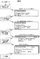
以下では、実施例における印刷データの生成処理を説明する前に、従来行われていた処理を比較例として説明する。図5は、比較例における印刷データの生成処理の手順と、その処理に使用されるバッファメモリとを示す説明図である。なお、図5の各ステップS1〜S5は、プリンタドライバ110内の各モジュールによって実行される。なお、プリンタドライバ110内の各モジュールを「処理部」とも呼ぶ。
【0024】
プリンタドライバ110は、アプリケーションプログラムからカラー画像データを受けると、ステップS1でRGBデータのラスタライズと解像度変換とを行って、印刷解像度Rprint(図2)を有するRGBデータを生成する。そして、このRGBデータをRGBデータバンドバッファBF1に格納する。ここで、「ラスタライズ」とは、主走査ライン毎にカラー画像データを配列する処理である。元のカラー画像データがビットマップデータである場合にはラスタライズは不要であるが、描画データや圧縮データの場合にはラスタライズが必要になる場合がある。
【0025】
なお、プリンタドライバ110がアプリケーションプログラムから受信するカラー画像データとしては、RGBデータやJPEGデータなどの種々のデータ構造を有するものを利用できる。通常のカラー画像データは、3つの色成分で任意の色を表現するデータである。
【0026】
プリンタドライバ110は、アプリケーションプログラムからRGBデータを受け取り、これを印刷解像度Rprintに単純水増ししてバンドバッファBF1に格納する。例えば、図2の例のように、元のRGBデータの解像度Rdataが360dpiであり、印刷解像度Rprintが720dpiである場合には、解像度変換では、元の1画素DPXの画素値が2×2個の印刷画素PPXに割り当てられる。
【0027】
図5のバンドバッファBF1は、1つのバンドBL(図2(A))分のRGBデータを格納する容量を有している。前述したように、バンドBLは、ドットデータ作成時の画像データの処理単位である。このバンドバッファBF1の容量CP[BF1]は、以下の(1)式で与えられる。
【0028】
CP[BF1]=W×Rprint×4×L …(1)
【0029】
ここで、値「4」は1画素分のRGBデータのバイト数である。なお、図5に示すように、バンドバッファBF1内の1画素分のRGBデータは、各8ビットのR,G,B成分と、8ビット分のスタッフビットXとで構成された4バイトのデータ構造を有している。ここで、W=8インチ,Rprint=720dpi,L=100ラインと仮定すると、バンドバッファBF1の容量CP[BF1]は、約2.2メガバイトとなる。
【0030】
ステップS2では、プリンタドライバ110が、バンドバッファBF1からRGBデータを順次読み出して色変換処理とディザ処理とを実行し、得られたドットデータをドットデータバンドバッファBF2に格納する。色変換処理は、図示しない色変換ルックアップテーブルを用いて、RGBデータを複数のインク色のデータ(「インク色データ」と呼ぶ)に変換する処理である。ディザ処理は、印刷解像度を有する所定の閾値パターンと、インク色データとを比較してドットデータを生成する処理である。
【0031】
ドットデータバンドバッファBF2は、1つのバンドBL分のドットデータを格納する容量を有している。このバンドバッファBF2の容量CP[BF2]は、以下の(2)式で与えられる。
【0032】
CP[BF2]=W×Rprint×(1/8)×L×Nc …(2)
【0033】
ここで、値「1/8」は1画素分のドットデータのバイト数である。すなわち、1インク色の1画素分のドットデータは、1ビット(すなわち1/8バイト)であるものとしている。一般に、1インク色の1画素分のドットデータがMビットのときには、容量CP[BF2]は(2)式のM倍になる。これは、後述する他の式でも同様である。上記(2)式において、W=8インチ,Rprint=720dpi,L=100ライン,Nc=7と仮定すると、バンドバッファBF2の容量CP[BF2]は、約0.5メガバイトとなる。
【0034】
ステップS3では、プリンタドライバ110が、ドット再配列処理(ステップS4)で使用されるドットデータを、バンドバッファBF2から読み出して再配列処理用バッファBF3に格納する。再配列処理用バッファBF3の容量CP[BF3]は、以下の(3)式で与えられる。
【0035】
CP[BF3]=W×Rprint×(1/8)×Nn×(Rprint/Rnozzle)×Nc …(3)
【0036】
なお、{Nn×(Rprint/Rnozzle)}の項は、図4に示すように、印刷ヘッド210の副走査方向の高さH1の範囲に存在する主走査ラインの数を示している。換言すれば、この高さH1は、カラー印刷時に使用される複数のノズル全体の副走査方向の高さに相当する。これから理解できるように、再配列処理用バッファBF3には、1回のパスにおいて走査される領域の副走査方向の範囲にわたるドットデータが格納される。この意味では、このバッファBF3に格納すべき必要最小限のデータは、印刷ヘッド210の両端のノズル位置を両端とする領域のデータであり、その副走査方向の高さは{(Nn−1)×(Rprint/Rnozzle)+1}となる。しかし、この値と上述の高さH1の値との差は小さく、両者は実質的に同じである。ここで、W=8インチ,Rprint=720dpi,Nn=180,Rnozzle=180dpi,Nc=7と仮定すると、(3)式で与えられるバンドバッファBF3の容量CP[BF3]は約3.5メガバイトとなる。
【0037】
ステップS4では、プリンタドライバ110がドットデータの再配列処理を実行して、1回のパスで使用されるドットデータを出力バッファBF4に格納する。再配列処理とは、1回のパスにおいて使用されるドットデータのみを抽出して再配列する処理である。例えば、図4のパス1では、印刷ヘッド210のノズルで走査される主走査ラインL1,L5,L9,…L37上の奇数番目の画素位置のみがドットの記録対象となる。従って、パス1を実行する場合には、この記録対象画素位置のドットデータだけを抽出してプリンタドライバ110からプリンタ200に供給すればよい。
【0038】
図6は、データ再配列処理の内容を示す説明図である。図6(A)には図4のパス1用の印刷データを作成する場合における再配列処理用バッファBF3内のドットデータと、印刷ヘッド210のノズル位置との関係が示されている。再配列処理用バッファBF3には、40本のラインL1〜L40のすべての画素位置のドットデータが格納されている。パス1では、主走査ラインL1,L5,L9…L37上の奇数画素位置のドットデータのみが使用される。従って、図6(B)に示すように、再配列処理では、これらの主走査ラインL1,L5,L9…L37上の奇数画素位置のドットデータのみが抽出されて出力バッファBF4に格納される。このとき、出力バッファBF4内において、主走査ラインL1,L5,L9…L37上の偶数画素位置(非記録対象画素位置)のドットデータは、ドットが形成されないことを示すダミーデータに置き換えられる。なお、出力バッファBF4としては、図6(C)のように、非記録対象画素位置のデータを含まず、記録対象画素位置のデータのみを含むものを使用してもよい。
【0039】
出力バッファBF4として図6(B)に示すものを使用する場合には、その容量CP[BF4]は、以下の以下の(4)式で与えられる。
【0040】
CP[BF4]=W×Rprint×(1/8)×Nn×Nc …(4)
【0041】
ここで、W=8インチ,Rprint=720dpi,Nn=180,Nc=7と仮定すると、出力バッファBF4の容量CP[BF4]は約0.9メガバイトとなる。
【0042】
ステップS5では、1パス分のドットデータが揃った後で、プリンタ200にドットデータが転送される。また、1パス分のドットデータが揃うと、再配列処理用バッファBF3内のドットデータのうちで、副走査送り量F(図4)に相当するライン数のドットデータが新たなドットデータに更新される。図4の例では、送り量Fは印刷解像度で5ライン分なので、5ライン分のドットデータが更新される。
【0043】
以上の比較例におけるバッファBF1〜BF4の合計容量は、約7.1メガバイトである。
【0044】
C.実施例の処理:
図7は、本発明の実施例における印刷データの生成処理の手順と、その処理に使用されるバッファメモリとを示す説明図である。図7の各ステップS11〜S15は、プリンタドライバ110内の各モジュールによって実行される。
【0045】
ステップS11では、プリンタドライバ110は、RGBデータのラスタライズを行って、画像データ解像度Rdata(図2)を有するRGBデータを生成し、RGBデータバンドバッファBF11に格納する。比較例のステップS1との違いは、RGBデータの解像度変換を行わずに、画像データ解像度RdataのままでバンドバッファBF11に格納する点である。このバンドバッファBF11の容量CP[BF11]は、以下の(5)式で与えられる。
【0046】
CP[BF11]=W×Rdata×4×L …(5)
【0047】
ここで、W=8インチ,Rdata=360dpi,L=100ラインと仮定すると、バンドバッファBF11の容量CP[BF11]は、約1.1メガバイトとなる。このバンドバッファBF11の容量は、比較例のバンドバッファBF1の容量(約2.2メガバイト)に、画像データ解像度Rdataと印刷解像度Rprintとの比(Rdata/Rprint)=1/2を乗じた値となっている。
【0048】
ステップS12では、プリンタドライバ110が、バンドバッファBF11からRGBデータを読み出してライン選択処理用バッファBF12に格納する。ライン選択処理用バッファBF12は、比較例における再配列処理用バッファBF3に類似するものであり、印刷ヘッド210の副走査方向の高さH1(図4)の範囲のカラー画像データ(RGBデータ)を格納するためのものである。図8(A)には、図4のパス1におけるライン選択処理用バッファBF12内の画像データと、印刷ヘッド210のノズル位置との関係が示されている。図4の高さH1に相当する高さH2に含まれる画像データのラインDL1〜DL20の数は、{Nn×(Rdata/Rnozzle)}である。すなわち、本実施例では、このライン数{Nn×(Rdata/Rnozzle)}が、カラー印刷時に使用される複数のノズル全体の副走査方向の高さに相当する。なお、バッファBF12に格納すべき必要最小限の画像データは、印刷ヘッド210の両端のノズル位置を両端とする領域のデータであり、その副走査方向の高さH2に相当する画像データのライン数は{(Nn−1)×(Rdata/Rnozzle)+1}となる。但し、この値と上記の値{Nn×(Rdata/Rnozzle)}との差は小さく、両者は実質的に同一である。
【0049】
ライン選択処理用バッファBF12の容量CP[BF12]は、以下の(6)式で与えられる。
【0050】
CP[BF12]=W×Rdata×4×Nn×(Rdata/Rnozzle) …(6)
【0051】
ここで、W=8インチ,Rdata=360dpi,Nn=180,Rnozzle=180dpiと仮定すると、バッファBF12の容量CP[BF12]は約4.0メガバイトとなる。
【0052】
ステップS13では、プリンタドライバ110が、1回のパスで記録対象となる画像データのラインを順次選択するとともに、色変換処理とディザ処理とを実行する。図9は、実施例における色変換処理とディザ処理の内容を示している。ここでは、印刷解像度の主走査ラインの中の最上部の主走査ラインL1を記録対象としている。この処理では、まず、記録対象ラインL1に対応する画像データのラインDL1が選択されて、ライン選択処理用バッファBF12から読み出される。そして、このラインDL1上の画素値がインク色データに色変換され、そのインク色データに対してディザ処理が行われる。ディザ処理では、選択されたラインDL1の画素P1,P2,P3…のインク色データと、プリンタドライバ110内に予め格納されている閾値マトリクスTMXとが比較される。閾値マトリクスTMXの各閾値は、印刷解像度Rprintの画素T1,T2…に対して割り当てられている。
【0053】
この比較によって、印刷解像度Rprintを有する主走査ラインL1上の画素位置におけるドットの記録状態を示すドットデータが得られる。こうして得られた各画素のドットデータは、ドットデータラインバッファBF13に順次格納される。図9に示されているように、主走査ラインL1上の1画素目のドットデータは、画像データのラインDL1の1番目の画素P1のインク色データと、閾値マトリクスTMXの1番目の画素T1の閾値とを比較した結果である。また、2画素目のドットデータは、画像データのラインDL1の1番目の画素P1のインク色データと、閾値マトリクスTMXの2番目の画素T2の閾値とを比較した結果である。この例から理解できるように、本実施例の色変換処理とディザ処理では、ライン選択処理用バッファBF12から、同一の画素値が(Rprint/Rdata)回ずつ繰り返し読み出されて処理が実行される。副走査方向にも同様に、同一の画素値が(Rprint/Rdata)回ずつ繰り返し読み出される。この回数の値(Rprint/Rdata)は、印刷解像度Rprintと画像データ解像度Rdataとの比の値である。このように、本実施例では、画像データの同一の画素値を(Rprint/Rdata)回ずつ繰り返し読み出して色変換処理とディザ処理とを実行するので、ライン選択処理用バッファBF12に格納される画像データのデータ量が少なくて済むという利点がある。
【0054】
ラインバッファBF13の容量CP[BF13]は、以下の(7)式で与えられる(図7)。
【0055】
CP[BF13]=W×Rprint×(1/8)×Nc …(7)
【0056】
ここで、W=8インチ,Rprint=720dpi,Nc=7と仮定すると、ラインバッファBF13の容量CP[BF13]は、約5キロバイト(約0.005メガバイト)となる。
【0057】
図7のステップS14では、プリンタドライバ110が、ドットデータラインバッファBF13からドットデータを読み出して水平ドット位置選択処理を行い、出力バッファBF14に格納する。水平ドット位置選択処理とは、ラインバッファBF13内のドットデータの中で、1回のパスにおいて使用されるドットデータのみを抽出する処理である。図4のパス1では主走査ラインL1上の奇数番目の画素位置のみがドットの記録対象となる。従って、パス1を実行する場合には、この記録対象画素位置のドットデータがステップS14で抽出される。他の主走査ラインに関しても同様である。
【0058】
図8(B)は、ドットデータラインバッファBF13に格納された主走査ラインL1のドットデータを示しており、図8(C)は、水平ドット位置選択処理後に出力バッファBF14に格納されたドットデータを示している。このとき、これらの主走査ラインL1上の偶数画素位置(非記録対象画素位置)のドットデータは、ドットが形成されないことを示すダミーデータに置き換えられる。なお、図6(C)で説明したように、出力バッファBF14としては、非記録対象画素位置のドットデータを含まず、記録対象画素位置のドットのみを含むものを使用してもよい。
【0059】
出力バッファBF14の容量CP[BF14]は、比較例と同じ以下の(8)式で与えられる。
【0060】
CP[BF14]=W×Rprint×1/8×Nn×Nc …(8)
【0061】
ここで、W=8インチ,Rprint=720dpi,Nn=180,Nc=7と仮定すると、出力バッファBF4の容量CP[BF4]は約0.9メガバイトとなる。
【0062】
ステップS15では、1パス分のドットデータが揃った後で、プリンタ200にドットデータが転送される。また、1パス分のドットデータが揃うと、ライン選択処理用バッファBF12内の画像データのうちで、副走査送り量F(図4)に相当するライン数の画像データが、新たな画像データに更新される。図4の例では、送り量Fは印刷解像度で5ライン分であり、画像データ解像度では2.5ラインに相当する。従って、1パス分の処理が終了すると、ライン選択処理用バッファBF12内の画像データのうち、必要に応じて2ライン分または3ライン分の画像データが更新される。
【0063】
以上の実施例におけるバッファBF11〜BF14の合計の容量は、約6.0メガバイトである。
【0064】
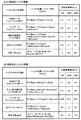
図10は、上述した比較例と実施例におけるバッファメモリの容量を比較して示す説明図である。印刷解像度Rprintが720dpiの場合には、比較例におけるバッファメモリの合計容量は約7.1メガバイトであり、実施例におけるバッファメモリの合計容量は約6.0メガバイトである。印刷解像度Rprintが1440dpiの場合には、比較例におけるバッファメモリの合計容量は約20.9メガバイトであり、実施例におけるバッファメモリの合計容量は約7.9メガバイトである。印刷解像度Rprintが2880dpiになると、比較例におけるバッファメモリの合計容量は約69.9メガバイトとなり、実施例におけるバッファメモリの合計容量は約11.9メガバイトになる。この説明から理解できるように、比較例においても実施例においても、印刷解像度Rprintの増加に応じてバッファメモリの容量が増大するが、実施例における増大率は比較例に比べて極めて小さい。この理由は、比較例においては印刷解像度Rprintの増加に応じて再配列処理用バッファBF3の容量が急激に増大しているからである。バッファ容量のパラメータ表示(図10の2番目の欄)から理解できるように、再配列処理用バッファBF3の容量は、印刷解像度Rprintの2乗に比例して増大する。これに対して、実施例では、印刷解像度Rprintの2乗に比例して容量が増大するバッファは使用していない。逆に、実施例のライン選択処理用バッファBF12は、印刷解像度Rprintが変わっても容量は変わらない。この両者の差が、合計容量の差となっていることが理解できる。
【0065】
このように、上記実施例では、比較例のようにドットデータを作成した後に再配列処理を行う代わりに、印刷ヘッド210の副走査方向の高さH2(図8)に相当する領域のカラー画像データをライン選択処理用バッファBF12に格納し、このバッファBF12から印刷対象となるラインの画像データを選択的に読み出して色変換処理やディザ処理を行うことによってドットデータを作成している。この結果、印刷解像度Rprintが増加しても、これに応じてバッファメモリの合計容量が過度に増大することを防止することができる。
【0066】
D.変形例:
以上、本発明のいくつかの実施の形態について説明したが、本発明はこのような実施の形態になんら限定されるものではなく、その要旨を逸脱しない範囲内において種々なる態様での実施が可能である。例えば、以下のような変形例も可能である。
【0067】
D1.変形例1:
上記実施例では、図7に示した処理をすべてプリンタドライバ110が行うものとしていたが、これらの処理の全部または一部をプリンタ200内のコントローラが実行するものとしてもよい。例えば、図7の例において、ステップS12までの処理をプリンタドライバ110が行い、ステップS13以降の処理をプリンタ200内のコントローラが行うものとしてもよい。この場合には、プリンタドライバ110が使用するバッファメモリの合計容量は約5.5メガバイトになり、プリンタ200のコントローラが使用するバッファメモリの合計容量は約0.9メガバイトになる。このように、カラー画像データから1パス分のドットデータを作成するためのドットデータ作成処理を、プリンタドライバ110とプリンタ200内のコントローラとで適宜分担することによって、それぞれで使用されるバッファメモリの容量を適切に配分することが可能である。
【0068】
なお、このような特徴を利用して、プリンタドライバ110が、図7のステップS11〜S15の処理をコンピュータ100とプリンタ200のいずれで実行するかを、印刷システムの環境に応じて適応的に決定するようことも可能である。例えば、印刷データ作成処理の実行に先だって、プリンタドライバ110がコンピュータ100内の利用可能なメモリ資源の残量を調べ、その調査結果に応じてステップS11〜S15の処理をコンピュータ100とプリンタ200のいずれで実行するかを切り換えるようにしてもよい。こうすれば、印刷時における印刷システムの環境に応じた適切な負荷配分を行うことができるので、より高速に印刷データを作成することが可能である。
【0069】
D2.変形例2:
上記実施例では、ディザ処理を行うことによってドットデータを作成していたが、カラー画像データを閾値パターンと比較するタイプの他のハーフトーン処理(例えば濃度パターン法)を利用することも可能である。
【0070】
D3.変形例3:
上記実施例では、ライン選択処理用バッファBF12(図7)にRGBデータを格納していたが、RGBデータの代わりに、L*a*b*表色系の画像データや、インク色への変換を行った後のインク色データを格納してもよい。インク色データをバッファBF12する場合にも、このインク色データが、元のカラー画像データの解像度と同じ解像度(実施例では360dpi)を有することが好ましい。そして、ライン選択処理用バッファBF12から読み出されたインク色データ(これもカラー画像データの一種である)に関して、印刷画素毎にディザ処理が行われる。なお、通常は、インク色の種類は4以上なので、ライン選択処理用バッファBF12にRGBデータなどの元のカラー画像データを格納する方が、バッファ容量の点から好ましい。
【0071】
上記の説明から理解できるように、ライン選択処理用バッファBF12から読み出されたカラー画像データに関しては、印刷解像度に従ったハーフトーン処理が少なくとも行われてドットデータが作成される。
【0072】
D4.変形例4:
図7に示した4種類のバッファBF11〜BF14のうち、バンドバッファBF11とドットデータラインバッファBF13は省略することも可能である。この場合には、ステップS11におけるラスタライズ後の画像データが、ライン選択処理用バッファBF12に直接格納される。また、ステップS13で1画素分のドットデータが作成されると、ラインバッファBF13に格納することなく、そのドットデータの要否を判断する水平ドット位置選択処理が実行され、必要な画素(記録対象画素)のドットデータのみが出力バッファBF14に格納される。
【0073】
D5.変形例5:
上記実施例では、インクジェットプリンタを用いているが、本発明は、他のタイプのプリンタにも適用可能である。
【図面の簡単な説明】
【図1】本発明の実施例としての印刷システムの構成を示すブロック図。
【図2】画像データ解像度Rdataと印刷解像度Rprintとの関係を示す説明図。
【図3】印刷ヘッド210の底面におけるノズル配列を示す説明図。
【図4】プリンタ200によって実行されるドット記録方式の一例を示す説明図。
【図5】比較例における印刷データの生成処理の手順を示す説明図。
【図6】比較例におけるデータ再配列処理の内容を示す説明図。
【図7】実施例における印刷データの生成処理の手順を示す説明図。
【図8】実施例で使用される3種類のバッファBF12〜BF14を示す説明図。
【図9】実施例における色変換処理とディザ処理の内容を示す説明図。
【図10】比較例と実施例におけるバッファメモリ容量を比較して示す説明図。
【符号の説明】
100…コンピュータ
110…プリンタドライバ
120…バッファメモリ
200…プリンタ[0001]
TECHNICAL FIELD OF THE INVENTION
The present invention relates to a technique for performing color printing by discharging ink from nozzles of a print head while performing main scanning.
[0002]
[Prior art]
Ink jet printers are widely used as output devices for computers. In recent years, the printing resolution of an ink jet printer tends to increase for higher image quality, and the number of nozzles per color tends to increase for higher speed.
[0003]
[Problems to be solved by the invention]
When printing is performed by an inkjet printer, a process of creating dot data representing the recording state of the ink dots of each ink from color image data such as RGB data is executed. In this processing, a large amount of buffer memory is used. However, as the printing resolution and the number of nozzles increase, the required capacity of the buffer memory also greatly increases. For example, if the printing resolution is doubled in both the main scanning direction and the sub-scanning direction, the number of pixels in the printing area is quadrupled. At this time, the capacity of the buffer memory is quadrupled by a simple calculation. Further, when the print resolution increases four times, the capacity of the buffer memory reaches sixteen times.
[0004]
However, there is a limit to the memory resources that can be used as a buffer memory. Therefore, conventionally, there has been a demand to reduce the capacity of the buffer memory required for the dot data creation processing.
[0005]
SUMMARY An advantage of some aspects of the invention is to provide a technique capable of reducing the capacity of a buffer memory required during dot data creation processing.
[0006]
[Means for Solving the Problems and Their Functions and Effects]
In order to solve at least a part of the problems described above, the method of the present invention is to perform color printing by discharging ink from nozzles of a print head while performing main scanning and recording ink dots on a print medium. A method for creating dot data indicating a recording state of ink dots,
(A) A plurality of nozzle groups for ejecting a plurality of types of inks, the plurality of nozzle groups each including a plurality of nozzles whose nozzle pitch along the sub-scanning direction is coarser than the pitch of print pixels. Preparing a print head,
(B) Color image data having a resolution lower than the printing resolution is prepared, and color image data in an area corresponding to the height in the sub-scanning direction of all of the plurality of nozzles used in color printing is stored in a first buffer. Storing in the
(C) selecting, from the first buffer, color image data representing a color image on a plurality of print target lines on which ink dots are to be recorded by the plurality of nozzle groups in one main scan;
(D) at least halftone processing using a threshold pattern having a printing resolution is performed on the color image data on the selected plurality of print target lines, so that the ink at the print pixels on the selected print target lines is obtained. Creating dot data indicating a dot recording state and storing the dot data in a second buffer;
(E) outputting the dot data from the second buffer;
Is provided.
[0007]
According to this method, the color image data stored in the first buffer is color image data having a resolution lower than the printing resolution, and is high in the sub-scanning direction of a plurality of nozzles used in color printing. This is the data for the area corresponding to this. Therefore, there is an effect that the capacity of the buffer memory does not excessively increase even when the print resolution increases.
[0008]
The color image data stored in the first buffer is expressed by a first color system that expresses an arbitrary color with three color components.
The step (d) may include, before the halftone processing, a step of converting the first color system into a second color system expressing an arbitrary color with the plurality of types of inks. Good.
[0009]
The print pixel position on each print target line where ink dots are to be recorded in one main scan is the print target pixel position where ink dots are to be recorded in the main scan, and the ink dot record target is And the non-recording target pixel position
The step (d) may include a step of replacing the value of the dot data at the non-recording target pixel position in the dot data on each print target line with a value representing the non-formation of a dot.
[0010]
The present invention can be realized in various aspects other than the above-described dot data creation method. For example, a printing method and a printing apparatus, a printing control method and a printing control apparatus, a printing system including a printing apparatus and a computer, The present invention can be realized in various forms such as a computer program for realizing the above method or apparatus, and a recording medium on which the program is recorded.
[0011]
BEST MODE FOR CARRYING OUT THE INVENTION
Hereinafter, embodiments of the present invention will be described in the following order based on examples.
A. Overview of the printing system:
B. Processing of Comparative Example:
C. Example processing:
D. Modification:
[0012]
A. Overview of the printing system:
FIG. 1 is a block diagram illustrating a configuration of a printing system according to an embodiment of the present invention. This printing system has a configuration in which a
[0013]
A program for realizing the function of the
[0014]
FIG. 2 is an explanatory diagram showing the relationship between the resolution Rdata of color image data received by the
[0015]
In the dot data creation processing executed by the
[0016]
FIG. 3 is an explanatory diagram showing the nozzle arrangement on the bottom surface of the
[0017]
Note that some nozzle groups (for example, black nozzle groups) may have more nozzles than other nozzle groups, and some of the nozzle groups may be smaller than the nozzle pitch of other nozzle groups. It may have a pitch. Even in such a case, the same number of nozzles are usually selected and used for each nozzle group when printing a color image. Generally, a print head having a plurality of nozzle groups for discharging a plurality of types of ink can be used as the
[0018]
FIG. 4 is an explanatory diagram illustrating an example of a recording method (printing method) performed using the
[0019]
In this example, each time one pass is completed, a sub-scan of a fixed feed amount F (= 5 dots) is performed. Although the print medium moves in the normal sub-scanning, in FIG. 4, for convenience of illustration, the
[0020]
In
[0021]
In this specification, the dot recording method as shown in FIG. 4 is referred to as “overlap recording method”. The “overlap recording method” is a method in which pixel positions on the main inspection line are intermittently and periodically recorded as ink dots in one pass. In other words, in the overlap recording method, the total number of main scans on each main scan line is two or more, and dots on each main scan line are recorded using two or more different nozzles. In the example of FIG. 4, the total number of main scans performed on each main scan line is two, but it can be set to three or more. Adopting such an overlap recording method has the advantage that the image position can be improved because the positional deviation of the dots due to the manufacturing error of the nozzles is reduced. However, the recording method in FIG. 4 is merely an example, and a recording method other than the overlap recording method may be employed.
[0022]
In the comparative examples and examples described below, the print data generation processing will be described using the following parameters.
The width W of the band BL (FIG. 2A): the width in the main scanning direction of the band BL, which is a processing unit of image data.
The height L of the band BL (FIG. 2A): the number of lines of the band BL in the sub-scanning direction.
Image data resolution Rdata (FIG. 2A): resolution of original color image data (RGB data).
Print resolution Rprint (FIG. 2B): Resolution at the time of printing. In the following description, it is assumed that print resolutions in the main scanning direction and the sub-scanning direction are equal.
Nozzle resolution Rnozzle (FIG. 3): a resolution that defines the pitch of the nozzles in the sub-scanning direction.
-Number of nozzles used Nn (Fig. 4): Number of nozzles per ink color used during color printing.
The number of ink colors Nc (FIG. 3): the number of ink colors used in color printing.
[0023]
B. Processing of Comparative Example:
Hereinafter, before describing the print data generation processing in the embodiment, a conventionally performed processing will be described as a comparative example. FIG. 5 is an explanatory diagram showing a procedure of print data generation processing in a comparative example and a buffer memory used for the processing. Steps S1 to S5 in FIG. 5 are executed by each module in the
[0024]
Upon receiving the color image data from the application program, the
[0025]
As the color image data received by the
[0026]
The
[0027]
The band buffer BF1 in FIG. 5 has a capacity to store RGB data for one band BL (FIG. 2A). As described above, the band BL is a processing unit of image data when creating dot data. The capacity CP [BF1] of the band buffer BF1 is given by the following equation (1).
[0028]
CP [BF1] = W × Rprint × 4 × L (1)
[0029]
Here, the value “4” is the number of bytes of RGB data for one pixel. As shown in FIG. 5, RGB data for one pixel in the band buffer BF1 is 4-byte data composed of R, G, and B components of 8 bits and a stuff bit X of 8 bits. It has a structure. Here, assuming that W = 8 inches, Rprint = 720 dpi, and L = 100 lines, the capacity CP [BF1] of the band buffer BF1 is about 2.2 megabytes.
[0030]
In step S2, the
[0031]
The dot data band buffer BF2 has a capacity to store dot data for one band BL. The capacity CP [BF2] of the band buffer BF2 is given by the following equation (2).
[0032]
CP [BF2] = W × Rprint × (1 /) × L × Nc (2)
[0033]
Here, the value “1 /” is the number of bytes of dot data for one pixel. That is, dot data for one pixel of one ink color is one bit (that is, 8 byte). Generally, when the dot data for one pixel of one ink color is M bits, the capacity CP [BF2] is M times as large as the equation (2). This is the same in other expressions described later. In the above equation (2), assuming that W = 8 inches, Rprint = 720 dpi, L = 100 lines, and Nc = 7, the capacity CP [BF2] of the band buffer BF2 is about 0.5 megabytes.
[0034]
In step S3, the
[0035]
CP [BF3] = W × Rprint × (1/8) × Nn × (Rprint / Rnozzle) × Nc (3)
[0036]
The term {Nn × (Rprint / Rnozzle)} indicates the number of main scan lines existing in the range of the height H1 of the
[0037]
In step S4, the
[0038]
FIG. 6 is an explanatory diagram showing the contents of the data rearrangement process. FIG. 6A shows the relationship between the dot data in the rearrangement processing buffer BF3 and the nozzle position of the
[0039]
When the output buffer BF4 shown in FIG. 6B is used, the capacitance CP [BF4] is given by the following equation (4).
[0040]
CP [BF4] = W × Rprint × (1 /) × Nn × Nc (4)
[0041]
Here, assuming that W = 8 inches, Rprint = 720 dpi, Nn = 180, and Nc = 7, the capacity CP [BF4] of the output buffer BF4 is about 0.9 megabytes.
[0042]
In step S5, the dot data is transferred to the
[0043]
The total capacity of the buffers BF1 to BF4 in the comparative example is about 7.1 megabytes.
[0044]
C. Example processing:
FIG. 7 is an explanatory diagram showing a procedure of print data generation processing and a buffer memory used for the processing in the embodiment of the present invention. Each step S11 to S15 in FIG. 7 is executed by each module in the
[0045]
In step S11, the
[0046]
CP [BF11] = W × Rdata × 4 × L (5)
[0047]
Here, assuming that W = 8 inches, Rdata = 360 dpi, and L = 100 lines, the capacity CP [BF11] of the band buffer BF11 is about 1.1 megabytes. The capacity of the band buffer BF11 is a value obtained by multiplying the capacity (about 2.2 megabytes) of the band buffer BF1 of the comparative example by the ratio (Rdata / Rprint) = 1/2 of the image data resolution Rdata and the print resolution Rprint. Has become.
[0048]
In step S12, the
[0049]
The capacity CP [BF12] of the line selection processing buffer BF12 is given by the following equation (6).
[0050]
CP [BF12] = W × Rdata × 4 × Nn × (Rdata / Rnozzle) (6)
[0051]
Here, assuming that W = 8 inches, Rdata = 360 dpi, Nn = 180, and Rnozzle = 180 dpi, the capacity CP [BF12] of the buffer BF12 is about 4.0 megabytes.
[0052]
In step S13, the
[0053]
By this comparison, dot data indicating the dot recording state at the pixel position on the main scanning line L1 having the print resolution Rprint is obtained. The dot data of each pixel thus obtained is sequentially stored in the dot data line buffer BF13. As shown in FIG. 9, the dot data of the first pixel on the main scanning line L1 is composed of the ink color data of the first pixel P1 of the image data line DL1 and the first pixel T1 of the threshold matrix TMX. It is a result of comparison with the threshold value. The dot data of the second pixel is a result of comparing the ink color data of the first pixel P1 of the line DL1 of the image data with the threshold value of the second pixel T2 of the threshold matrix TMX. As can be understood from this example, in the color conversion processing and the dither processing of the present embodiment, the same pixel value is repeatedly read out (Rprint / Rdata) times from the line selection processing buffer BF12, and the processing is executed. . Similarly, in the sub-scanning direction, the same pixel value is repeatedly read out (Rprint / Rdata) times. The value of the number of times (Rprint / Rdata) is a value of a ratio between the print resolution Rprint and the image data resolution Rdata. As described above, in the present embodiment, since the same pixel value of the image data is repeatedly read (Rprint / Rdata) times and the color conversion processing and the dither processing are performed, the image stored in the line selection processing buffer BF12 is obtained. There is an advantage that the data amount of data is small.
[0054]
The capacity CP [BF13] of the line buffer BF13 is given by the following equation (7) (FIG. 7).
[0055]
CP [BF13] = W × Rprint × (1/8) × Nc (7)
[0056]
Here, assuming that W = 8 inches, Rprint = 720 dpi, and Nc = 7, the capacity CP [BF13] of the line buffer BF13 is about 5 kilobytes (about 0.005 megabytes).
[0057]
In step S14 of FIG. 7, the
[0058]
FIG. 8B shows the dot data of the main scanning line L1 stored in the dot data line buffer BF13, and FIG. 8C shows the dot data stored in the output buffer BF14 after the horizontal dot position selection processing. Is shown. At this time, the dot data at even-numbered pixel positions (non-recording target pixel positions) on the main scanning line L1 is replaced with dummy data indicating that no dots are formed. As described with reference to FIG. 6C, the output buffer BF14 may not include the dot data at the non-recording target pixel position, and may include only the dot at the recording target pixel position.
[0059]
The capacity CP [BF14] of the output buffer BF14 is given by the following equation (8), which is the same as in the comparative example.
[0060]
CP [BF14] = W × Rprint × 1/8 × Nn × Nc (8)
[0061]
Here, assuming that W = 8 inches, Rprint = 720 dpi, Nn = 180, and Nc = 7, the capacity CP [BF4] of the output buffer BF4 is about 0.9 megabytes.
[0062]
In step S15, the dot data is transferred to the
[0063]
The total capacity of the buffers BF11 to BF14 in the above embodiment is about 6.0 megabytes.
[0064]
FIG. 10 is an explanatory diagram showing a comparison between the capacities of the buffer memories in the comparative example and the embodiment. When the print resolution Rprint is 720 dpi, the total capacity of the buffer memory in the comparative example is about 7.1 megabytes, and the total capacity of the buffer memory in the embodiment is about 6.0 megabytes. When the print resolution Rprint is 1440 dpi, the total capacity of the buffer memory in the comparative example is about 20.9 megabytes, and the total capacity of the buffer memory in the example is about 7.9 megabytes. When the print resolution Rprint becomes 2880 dpi, the total capacity of the buffer memory in the comparative example becomes about 69.9 megabytes, and the total capacity of the buffer memory in the embodiment becomes about 11.9 megabytes. As can be understood from this description, in both the comparative example and the embodiment, the capacity of the buffer memory increases as the print resolution Rprint increases, but the rate of increase in the embodiment is much smaller than in the comparative example. The reason for this is that in the comparative example, the capacity of the rearrangement processing buffer BF3 increases rapidly as the print resolution Rprint increases. As can be understood from the buffer capacity parameter display (the second column in FIG. 10), the capacity of the rearrangement processing buffer BF3 increases in proportion to the square of the print resolution Rprint. On the other hand, in the embodiment, a buffer whose capacity increases in proportion to the square of the print resolution Rprint is not used. Conversely, the capacity of the line selection processing buffer BF12 of the embodiment does not change even when the print resolution Rprint changes. It can be understood that the difference between the two is the difference in the total capacity.
[0065]
As described above, in the above-described embodiment, instead of performing the rearrangement process after creating the dot data as in the comparative example, the color image of the area corresponding to the height H2 of the
[0066]
D. Modification:
As described above, some embodiments of the present invention have been described, but the present invention is not limited to such embodiments at all, and can be implemented in various modes without departing from the gist thereof. It is. For example, the following modifications are also possible.
[0067]
D1.
In the above embodiment, all of the processing shown in FIG. 7 is performed by the
[0068]
Utilizing such features, the
[0069]
D2. Modified example 2:
In the above embodiment, the dot data is created by performing the dither processing. However, other halftone processing (for example, a density pattern method) of a type that compares color image data with a threshold pattern can be used. .
[0070]
D3. Modification 3:
In the above embodiment, the RGB data is stored in the line selection processing buffer BF12 (FIG. 7). However, instead of the RGB data, conversion into L * a * b * color image data or ink color is performed. May be stored. Even when the ink color data is buffered in the buffer BF12, it is preferable that the ink color data has the same resolution (360 dpi in the embodiment) as the resolution of the original color image data. Then, dither processing is performed for each print pixel for the ink color data (also a type of color image data) read from the line selection processing buffer BF12. Normally, since there are four or more types of ink colors, it is preferable to store original color image data such as RGB data in the line selection processing buffer BF12 from the viewpoint of buffer capacity.
[0071]
As can be understood from the above description, the color image data read from the line selection processing buffer BF12 is subjected to at least halftone processing in accordance with the print resolution to generate dot data.
[0072]
D4. Modification 4:
Of the four types of buffers BF11 to BF14 shown in FIG. 7, the band buffer BF11 and the dot data line buffer BF13 can be omitted. In this case, the rasterized image data in step S11 is directly stored in the line selection processing buffer BF12. When dot data for one pixel is created in step S13, horizontal dot position selection processing for determining whether or not the dot data is necessary is executed without storing the dot data in the line buffer BF13. Only the dot data of (pixel) is stored in the output buffer BF14.
[0073]
D5. Modification 5:
Although the above embodiment uses an ink jet printer, the present invention is applicable to other types of printers.
[Brief description of the drawings]
FIG. 1 is a block diagram illustrating a configuration of a printing system according to an embodiment of the present invention.
FIG. 2 is an explanatory diagram showing a relationship between image data resolution Rdata and print resolution Rprint.
FIG. 3 is an explanatory diagram showing a nozzle arrangement on a bottom surface of a
FIG. 4 is an explanatory diagram showing an example of a dot recording method executed by the
FIG. 5 is an explanatory diagram showing a procedure of print data generation processing in a comparative example.
FIG. 6 is an explanatory diagram showing the contents of a data rearrangement process in a comparative example.
FIG. 7 is an explanatory diagram showing a procedure of print data generation processing in the embodiment.
FIG. 8 is an explanatory diagram showing three types of buffers BF12 to BF14 used in the embodiment.
FIG. 9 is an explanatory diagram showing the contents of a color conversion process and a dither process in the embodiment.
FIG. 10 is an explanatory diagram showing a comparison between buffer memory capacities in a comparative example and an embodiment.
[Explanation of symbols]
100 ... Computer
110 ... Printer driver
120: buffer memory
200 ... Printer
Claims (5)
(a)複数種類のインクを吐出するための複数のノズル群であって、副走査方向に沿ったノズルピッチが印刷画素のピッチよりも粗い複数のノズルでそれぞれ構成された複数のノズル群を備えた印刷ヘッドを準備する工程と、
(b)印刷解像度よりも粗い解像度を有するカラー画像データを準備するとともに、カラー印刷時に使用される複数のノズル全体の副走査方向の高さに相当する領域のカラー画像データを、第1のバッファに格納する工程と、
(c)1回の主走査において前記複数のノズル群によってインクドットの記録対象となる複数の印刷対象ライン上のカラー画像を表すカラー画像データを、前記第1のバッファから選択する工程と、
(d)前記選択された複数の印刷対象ライン上のカラー画像データに関して、印刷解像度を有する閾値パターンを用いたハーフトーン処理を少なくとも行うことによって、前記選択された印刷対象ライン上の印刷画素におけるインクドットの記録状態を示すドットデータを作成して第2のバッファに格納する工程と、
(e)前記第2のバッファから前記ドットデータを出力する工程と、
を備える方法。In order to perform color printing by discharging ink from the nozzles of the print head while performing main scanning and recording ink dots on a print medium, a method of creating dot data indicating the recording state of ink dots,
(A) A plurality of nozzle groups for ejecting a plurality of types of inks, the plurality of nozzle groups each including a plurality of nozzles whose nozzle pitch along the sub-scanning direction is coarser than the pitch of print pixels. Preparing a print head,
(B) Color image data having a resolution lower than the printing resolution is prepared, and color image data in an area corresponding to the height in the sub-scanning direction of all of the plurality of nozzles used in color printing is stored in a first buffer. Storing in the
(C) selecting, from the first buffer, color image data representing a color image on a plurality of print target lines on which ink dots are to be recorded by the plurality of nozzle groups in one main scan;
(D) at least halftone processing using a threshold pattern having a printing resolution is performed on the color image data on the selected plurality of print target lines, so that the ink at the print pixels on the selected print target lines is obtained. Creating dot data indicating a dot recording state and storing the dot data in a second buffer;
(E) outputting the dot data from the second buffer;
A method comprising:
前記第1のバッファに格納される前記カラー画像データは、3つの色成分で任意の色を表現する第1の表色系によって表現されており、
前記工程(d)は、前記ハーフトーン処理の前に、前記第1の表色系から前記複数種類のインクで任意の色を表現する第2の表色系に変換する工程を含む、
方法。The method of claim 1, wherein
The color image data stored in the first buffer is represented by a first color system that represents an arbitrary color with three color components,
The step (d) includes a step of converting the first color system into a second color system expressing an arbitrary color with the plurality of types of inks before the halftone processing.
Method.
前記1回の主走査においてインクドットの記録対象となる各印刷対象ライン上の印刷画素位置が、当該主走査においてインクドットの記録対象となる記録対象画素位置と、インクドットの記録対象とならない非記録対象画素位置とを含んでいるときに、
前記工程(d)は、各印刷対象ライン上のドットデータの中で前記非記録対象画素位置におけるドットデータの値を、ドットの非形成を表す値に置き換える工程を含む、方法。The method according to claim 1 or 2, wherein
The print pixel position on each print target line where ink dots are to be recorded in one main scan is the same as the print target pixel position where ink dots are to be recorded in the main scan and the non-print target pixel where ink dots are not to be recorded. When the position of the pixel to be recorded is included,
The method (d) includes a step of replacing the value of the dot data at the non-recording target pixel position in the dot data on each print target line with a value representing the non-formation of a dot.
印刷解像度よりも粗い解像度を有するカラー画像データを準備するとともに、カラー印刷時に使用される複数のノズル全体の副走査方向の高さに相当する領域のカラー画像データを、第1のバッファに格納する第1の処理部と、
1回の主走査において前記複数のノズル群によってインクドットの記録対象となる複数の印刷対象ライン上のカラー画像を表すカラー画像データを、前記第1のバッファから選択する第2の処理部と、
前記選択された複数の印刷対象ライン上のカラー画像データに関して、印刷解像度を有する閾値パターンを用いたハーフトーン処理を少なくとも行うことによって、前記選択された印刷対象ライン上の印刷画素におけるインクドットの記録状態を示すドットデータを作成して第2のバッファに格納する第3の処理部と、
前記第2のバッファから前記ドットデータを出力する第4の処理部と、
を備える印刷制御装置。A print head including a plurality of nozzle groups for discharging a plurality of types of inks, the plurality of nozzle groups each including a plurality of nozzles in which a nozzle pitch along a sub-scanning direction is coarser than a pitch of print pixels. In order to perform color printing by ejecting ink from the nozzles of the print head while performing main scanning and recording ink dots on a print medium, printing that creates dot data indicating the recording state of ink dots A control device,
In addition to preparing color image data having a resolution lower than the printing resolution, color image data of an area corresponding to the height in the sub-scanning direction of the plurality of nozzles used in color printing is stored in the first buffer. A first processing unit;
A second processing unit that selects, from the first buffer, color image data representing a color image on a plurality of print target lines on which ink dots are to be recorded by the plurality of nozzle groups in one main scan;
Recording of ink dots at print pixels on the selected print target line by performing at least halftone processing using a threshold pattern having a print resolution on the color image data on the selected plurality of print target lines. A third processing unit that creates dot data indicating a state and stores the dot data in a second buffer;
A fourth processing unit that outputs the dot data from the second buffer;
A print control device comprising:
(a)印刷解像度よりも粗い解像度を有するカラー画像データを受け取り、カラー印刷時に使用される複数のノズル全体の副走査方向の高さに相当する領域のカラー画像データを第1のバッファに格納する機能と、
(b)1回の主走査において前記複数のノズル群によってインクドットの記録対象となる複数の印刷対象ライン上のカラー画像を表すカラー画像データを、前記第1のバッファから選択する機能と、
(c)前記選択された複数の印刷対象ライン上のカラー画像データに関して、印刷解像度を有する閾値パターンを用いたハーフトーン処理を少なくとも行うことによって、前記選択された印刷対象ライン上の印刷画素におけるインクドットの記録状態を示すドットデータを作成して第2のバッファに格納する機能と、
(d)前記第2のバッファから前記ドットデータを出力する機能と、
をコンピュータに実現させるコンピュータプログラム。A print head including a plurality of nozzle groups for discharging a plurality of types of inks, the plurality of nozzle groups each including a plurality of nozzles in which a nozzle pitch along a sub-scanning direction is coarser than a pitch of print pixels. In order to perform color printing by discharging ink from the nozzles of the print head while performing main scanning and recording ink dots on a print medium, to create dot data indicating the recording state of ink dots Computer program,
(A) Receiving color image data having a resolution lower than the printing resolution, and storing the color image data in an area corresponding to the height in the sub-scanning direction of the plurality of nozzles used in color printing in the first buffer. Features and
(B) a function of selecting, from the first buffer, color image data representing a color image on a plurality of print target lines on which ink dots are to be recorded by the plurality of nozzle groups in one main scan;
And (c) performing at least halftone processing using a threshold pattern having a print resolution on the color image data on the selected plurality of print target lines, thereby forming ink at print pixels on the selected print target lines. A function of creating dot data indicating a dot recording state and storing the dot data in a second buffer;
(D) a function of outputting the dot data from the second buffer;
A computer program that causes a computer to realize
Priority Applications (2)
| Application Number | Priority Date | Filing Date | Title |
|---|---|---|---|
| JP2003048823A JP2004255700A (en) | 2003-02-26 | 2003-02-26 | Process for creating dot data while saving memory capacity |
| US10/785,481 US20040227965A1 (en) | 2003-02-26 | 2004-02-25 | Dot data creation process with saved memory capacity |
Applications Claiming Priority (1)
| Application Number | Priority Date | Filing Date | Title |
|---|---|---|---|
| JP2003048823A JP2004255700A (en) | 2003-02-26 | 2003-02-26 | Process for creating dot data while saving memory capacity |
Publications (2)
| Publication Number | Publication Date |
|---|---|
| JP2004255700A true JP2004255700A (en) | 2004-09-16 |
| JP2004255700A5 JP2004255700A5 (en) | 2005-10-27 |
Family
ID=33114674
Family Applications (1)
| Application Number | Title | Priority Date | Filing Date |
|---|---|---|---|
| JP2003048823A Withdrawn JP2004255700A (en) | 2003-02-26 | 2003-02-26 | Process for creating dot data while saving memory capacity |
Country Status (2)
| Country | Link |
|---|---|
| US (1) | US20040227965A1 (en) |
| JP (1) | JP2004255700A (en) |
Cited By (2)
| Publication number | Priority date | Publication date | Assignee | Title |
|---|---|---|---|---|
| JP2009213111A (en) * | 2008-02-06 | 2009-09-17 | Canon Inc | Image processor, image processing method and program therefor, and storage medium |
| JP2010006062A (en) * | 2008-05-28 | 2010-01-14 | Seiko Epson Corp | Printing method using inkjet recording method and printing apparatus |
Families Citing this family (3)
| Publication number | Priority date | Publication date | Assignee | Title |
|---|---|---|---|---|
| JP4641459B2 (en) * | 2005-07-08 | 2011-03-02 | キヤノン株式会社 | Information processing apparatus and printer driver |
| SG189040A1 (en) | 2010-10-15 | 2013-05-31 | Zamtec Ltd | Multiple monochromatic print cartridge printing system and print alignment method |
| JP5633364B2 (en) * | 2010-12-24 | 2014-12-03 | コニカミノルタ株式会社 | Image processing device |
Family Cites Families (14)
| Publication number | Priority date | Publication date | Assignee | Title |
|---|---|---|---|---|
| JP2501195B2 (en) * | 1986-04-30 | 1996-05-29 | シャープ株式会社 | Color image processing device |
| US4978971A (en) * | 1989-11-06 | 1990-12-18 | Tektronix, Inc. | Method and apparatus for reformatting print data |
| US5574832A (en) * | 1992-08-03 | 1996-11-12 | Hewlett-Packard Corporation | Double axis dot depletion for 600 DPI edge acuity with 300 DPI print cartridge |
| CA2169902A1 (en) * | 1995-03-16 | 1996-09-17 | Allan Chiwan Cheung | Combined color halftoning |
| US5984446A (en) * | 1995-04-12 | 1999-11-16 | Eastman Kodak Company | Color office printer with a high capacity digital page image store |
| US5805178A (en) * | 1995-04-12 | 1998-09-08 | Eastman Kodak Company | Ink jet halftoning with different ink concentrations |
| US6415065B1 (en) * | 1995-08-04 | 2002-07-02 | Canon Kabushiki Kaisha | Image processing apparatus and method therefor |
| JPH09286125A (en) * | 1996-04-23 | 1997-11-04 | Canon Inc | Method for ink jet recording and apparatus therefor |
| US6067405A (en) * | 1997-03-04 | 2000-05-23 | Hewlett-Packard Company | Multipass color printmasks based on location rules to minimize hue shift, banding and coalescence |
| US6166828A (en) * | 1997-07-28 | 2000-12-26 | Canon Kabushiki Kaisha | Clearing ink jet nozzles during printing |
| JP3490873B2 (en) * | 1997-10-03 | 2004-01-26 | フーリエ有限会社 | Printing equipment |
| US6313922B1 (en) * | 1998-07-16 | 2001-11-06 | Hewlett-Packard Company | Efficient use of a printhead and a compressed swath buffer in an inkjet printer |
| AUPQ056099A0 (en) * | 1999-05-25 | 1999-06-17 | Silverbrook Research Pty Ltd | A method and apparatus (pprint01) |
| FR2801396B1 (en) * | 1999-11-22 | 2002-11-08 | Canon Kk | CONVERTING TO DIGITAL DATA POINT MODE |
-
2003
- 2003-02-26 JP JP2003048823A patent/JP2004255700A/en not_active Withdrawn
-
2004
- 2004-02-25 US US10/785,481 patent/US20040227965A1/en not_active Abandoned
Cited By (5)
| Publication number | Priority date | Publication date | Assignee | Title |
|---|---|---|---|---|
| JP2009213111A (en) * | 2008-02-06 | 2009-09-17 | Canon Inc | Image processor, image processing method and program therefor, and storage medium |
| KR101019663B1 (en) * | 2008-02-06 | 2011-03-07 | 캐논 가부시끼가이샤 | Image processing device and image processing method |
| US8094342B2 (en) | 2008-02-06 | 2012-01-10 | Canon Kabushiki Kaisha | Image processing device that retains a high resolution dithering matrix and image processing method therefor |
| JP2010006062A (en) * | 2008-05-28 | 2010-01-14 | Seiko Epson Corp | Printing method using inkjet recording method and printing apparatus |
| JP2015006795A (en) * | 2008-05-28 | 2015-01-15 | セイコーエプソン株式会社 | Printing method and printing device of inkjet recording system |
Also Published As
| Publication number | Publication date |
|---|---|
| US20040227965A1 (en) | 2004-11-18 |
Similar Documents
| Publication | Publication Date | Title |
|---|---|---|
| JP4078811B2 (en) | Printing that reproduces gradation with dark and light ink in pixel block units | |
| US6834926B2 (en) | Ink-jet printing apparatus and method, and computer readable memory | |
| US8215741B2 (en) | Inkjet printer and printing method | |
| WO2000040001A1 (en) | Method and device for image processing | |
| JP3981480B2 (en) | Printing apparatus and recording medium | |
| US6467866B1 (en) | Print control method and apparatus, and printing apparatus using the same | |
| US7328964B2 (en) | Image processor, image processing method, printer, printing method, program, and recording medium | |
| JP4837937B2 (en) | Inkjet printer and printer driver | |
| JP3687381B2 (en) | Printing apparatus, printing method, and recording medium | |
| JP2004255700A (en) | Process for creating dot data while saving memory capacity | |
| US20030137556A1 (en) | Draft printing with multiple same-hue ink nozzles | |
| JP4691880B2 (en) | An image output device that outputs an image while converting resolution of data of a plurality of pixel columns in which dots are formed simultaneously | |
| JP4785351B2 (en) | Inkjet recording apparatus, inkjet recording method, data generation apparatus, and program | |
| JP6259951B2 (en) | Image forming method | |
| JP4535081B2 (en) | Printing apparatus and recording medium | |
| US6325486B1 (en) | Image recording method | |
| JP7332367B2 (en) | Image processing device and image processing method | |
| JP2004209989A (en) | Printer, printing method, and recording medium | |
| JP2005007800A (en) | System for printing image based on information of the number of dots formed in specified region | |
| US11386311B2 (en) | Recording device and recording method using halftone processing technique | |
| JP2019107810A (en) | Image processing device, image processing method and inkjet recording device | |
| JP4007179B2 (en) | Printing system that prints while performing image processing by sharing between image processing device and printing device | |
| US20230385584A1 (en) | Printing apparatus, method of controlling printing apparatus, and storage medium | |
| JP3757650B2 (en) | Image processing device | |
| JP3596313B2 (en) | Printing apparatus, printing method, and recording medium |
Legal Events
| Date | Code | Title | Description |
|---|---|---|---|
| A521 | Written amendment |
Free format text: JAPANESE INTERMEDIATE CODE: A523 Effective date: 20050714 |
|
| A621 | Written request for application examination |
Free format text: JAPANESE INTERMEDIATE CODE: A621 Effective date: 20050714 |
|
| A977 | Report on retrieval |
Free format text: JAPANESE INTERMEDIATE CODE: A971007 Effective date: 20071128 |
|
| A131 | Notification of reasons for refusal |
Free format text: JAPANESE INTERMEDIATE CODE: A131 Effective date: 20080205 |
|
| RD04 | Notification of resignation of power of attorney |
Free format text: JAPANESE INTERMEDIATE CODE: A7424 Effective date: 20080313 |
|
| A521 | Written amendment |
Free format text: JAPANESE INTERMEDIATE CODE: A523 Effective date: 20080404 |
|
| RD03 | Notification of appointment of power of attorney |
Free format text: JAPANESE INTERMEDIATE CODE: A7423 Effective date: 20080404 |
|
| A131 | Notification of reasons for refusal |
Free format text: JAPANESE INTERMEDIATE CODE: A131 Effective date: 20081216 |
|
| A521 | Written amendment |
Free format text: JAPANESE INTERMEDIATE CODE: A523 Effective date: 20090213 |
|
| A131 | Notification of reasons for refusal |
Free format text: JAPANESE INTERMEDIATE CODE: A131 Effective date: 20090602 |
|
| A761 | Written withdrawal of application |
Free format text: JAPANESE INTERMEDIATE CODE: A761 Effective date: 20090729 |