JP2004251075A - Siphon type rainwater draining device - Google Patents
Siphon type rainwater draining device Download PDFInfo
- Publication number
- JP2004251075A JP2004251075A JP2003044928A JP2003044928A JP2004251075A JP 2004251075 A JP2004251075 A JP 2004251075A JP 2003044928 A JP2003044928 A JP 2003044928A JP 2003044928 A JP2003044928 A JP 2003044928A JP 2004251075 A JP2004251075 A JP 2004251075A
- Authority
- JP
- Japan
- Prior art keywords
- siphon
- eaves gutter
- pipe
- drainage device
- rainwater
- Prior art date
- Legal status (The legal status is an assumption and is not a legal conclusion. Google has not performed a legal analysis and makes no representation as to the accuracy of the status listed.)
- Granted
Links
Images


Classifications
-
- E—FIXED CONSTRUCTIONS
- E04—BUILDING
- E04D—ROOF COVERINGS; SKY-LIGHTS; GUTTERS; ROOF-WORKING TOOLS
- E04D13/00—Special arrangements or devices in connection with roof coverings; Protection against birds; Roof drainage; Sky-lights
- E04D13/04—Roof drainage; Drainage fittings in flat roofs, balconies or the like
- E04D13/08—Down pipes; Special clamping means therefor
- E04D2013/0893—Down pipes; Special clamping means therefor incorporated in building structure
Abstract
Description
【0001】
【発明の属する技術分野】
本発明は、大雨のときに雨水を極めて効率良く排水できるサイホン式雨水排水装置に関する。
【0002】
【従来の技術】
従来の家屋は、軒樋を上合(集水器)に向かって流れ勾配が付くように軒先に取付け、上合に流入した雨水を堅樋を通じて自然落下させることにより排水していた。けれども、軒樋に流れ勾配が付いていると家屋の外観が良くないため、最近の住宅では、流れ勾配を付けないで軒樋を水平に取付ける場合が増えている。
【0003】
【発明が解決しようとする課題】
しかしながら、従来のように雨水を軒樋で上合に集めて堅樋内部を自然落下させる排水装置は排水効率があまり良くなく、特に、軒樋が水平に取付けられている場合は、上合から遠ざかるほど排水効率が低下して軒樋内部の水位が上昇することになる。そのため、本来必要な容量以上の大きい軒樋を取付けたり、上合と上合の間隔を狭めることが必要になり、コストアップを招くと共に、上合や堅樋の増加で家屋の外観も損なわれるという問題があった。
【0004】
本発明は上記の問題に対処すべくなされたもので、その目的とするところは、大雨のときにサイホン作用により大量の雨水を極めて効率良く排水でき、コストアップや家屋の外観を損なうこともないサイホン式雨水排水装置を提供することにある。
【0005】
【課題を解決するための手段】
上記目的を達成するため、本発明に係るサイホン式雨水排水装置は、軒樋の底部にサイホン管路が軒樋全長に亘って設けられると共に、軒樋の内側からサイホン管路に通じる吸水口が設けられ、家屋の外壁材に沿って縦方向に設けられた縦サイホン管路の上端が上記軒樋のサイホン管路に接続されていることを特徴とするものである。
【0006】
このようなサイホン式雨水排水装置は、小雨のときには、屋根から軒樋に流れ込んだ雨水が軒樋底部の吸水口からサイホン管路に流入し、縦サイホン管路内を自然落下して排水される。そして、大雨のときには、吸水口から軒樋底部のサイホン管路への流入量が増加し、軒樋底部のサイホン管路と縦サイホン管路が雨水で満たされると、サイホン作用によって雨水が吸水口から吸い込まれて自然落下排水の数倍の流速で軒樋底部のサイホン管路と縦サイホン管路を流れ落ち、多量の雨水が極めて効率良く排水される。従って、本発明のサイホン式雨水排水装置は、軒樋として従来より小さいものが使用可能であり、また、縦サイホン管路の接続箇所の間隔を従来の堅樋間隔より広げて縦サイホン管路の接続箇所を少なくすることもできるので、コストアップや家屋の外観を損なう心配がない。
【0007】
本発明のサイホン式雨水排水装置においては、軒樋底部のサイホン管路や外壁材沿いの縦サイホン管路の開口面積を2〜20cm2とすることが好ましく、かかる開口面積にすると良好なサイホン作用が発揮される。開口面積が20cm2より大きくなると、大雨のときでも軒樋底部のサイホン管路や縦サイホン管路が雨水で満たされ難くなるため、サイホン作用を十分発揮できない恐れが生じる。
これらの管路内をサイホン作用によって流れる雨水の流速は速いので、これらの管路の開口面積がある程度小さくても、ゴミその他の固形物は洗い流されて管路内に詰まることはないが、それでも開口面積が2cm2より小さくなるとゴミ等が詰まりやすくなる。
【0008】
本発明のサイホン式雨水排水装置においては、吸水口にゴミ除けカバーを取付けることが好ましく、このようにすると、軒樋底部のサイホン管路や縦サイホン管路のゴミ詰まりをより確実に防止することができる。
【0009】
本発明のサイホン式雨水排水装置においては、軒樋の底部に複数のサイホン管路を並列に設けると共に、軒樋を全長に亘ってサイホン管路と同数の吸水ゾーンに区画し、各サイホン管路に通じる吸水口を各サイホン管路に対応する吸水ゾーンに設けることが好ましい。このようにすると、家屋の屋根から軒樋に流れ込んだ雨水を、軒樋のそれぞれの吸水ゾーンの吸水口からほぼ均等にサイホン管路へ吸水できるため、軒樋全長に亘って水位がほぼ一定となる。従って、水位が部分的に高くなって雨水が軒樋から溢れ出すことがないので、軒樋として容量の小さいものを使用できるようになる。
【0010】
上記のように複数のサイホン管路を軒樋の底部に設ける場合は、この軒樋底部のサイホン管路と同数のサイホンT形合流管路を並列に形成した上合と、軒樋底部のサイホン管路と同数のサイホン短管路を並列に且つ90°捻じって形成した捻じり継手と、軒樋底部のサイホン管路と同数のサイホン曲管路を並列に形成したエルボ継手と、軒樋底部のサイホン管路と同数のサイホン直管路を並列に形成した堅樋部材とを組み合わせて接続することにより、軒樋底部のサイホン管路と同数の縦サイホン管路を設けると共に、上合と軒樋を接続することによってそれぞれの縦サイホン管路を軒樋底部のそれぞれのサイホン管路に接続することが好ましい。
【0011】
また、本発明のサイホン式雨水排水装置は、軒樋の底部に単数のサイホン管路を設けると共に、縦サイホン管路となる可撓性のサイホンチューブの上端を軒樋底部のサイホン管路に接続し、吸水口の位置をサイホンチューブの接続箇所から軒樋の長手方向両側にずらせる構成とすることも好ましい。このようにすると、屈曲自在な縦サイホン管路を容易に形成でき、しかも、吸水口の位置がサイホンチューブ接続箇所からずれているため空気を吸い込んでサイホン作用が停止する心配も解消される。
【0012】
上記のように軒樋の底部に単数のサイホン管路を設けてサイホンチューブを接続する場合は、サイホン管路のサイホンチューブ接続箇所の上面に掃除口を形成して、該掃除口にキャップを脱着自在に取付けることが好ましく、また、サイホンチューブを軒天の裏側から家屋外壁材の裏側の内壁材との中空部を通して地中の雨水ますに接続することが好ましい。このようにすると、掃除口からキャップを取り外して線状の掃除具等でサイホンチューブや軒樋底部のサイホン管路を簡単に清掃することが可能となり、また、サイホンチューブが屋外に露出しないので家屋の外観を向上させることができる。
【0013】
【発明の実施の形態】
以下、図面を参照して本発明の実施形態を詳述する。
【0014】
図1は本発明の一実施形態に係るサイホン式雨水排水装置の全体図、図2は同装置の軒樋の平面図、図3は同軒樋の横断面図、図4は同装置の上合と軒樋との接続部分を示す平面図、図5は同接続部分の正面図、図6は同上合の斜視図、図7(a)は図6のA−A線断面図、図7(b)は図6のB−B線断面図、図8は同装置の軒樋と上合と捻じり継手とエルボ継手を接続した部分の正面図、図9は同捻じり継手を示すもので(a)は平面図、(b)は正面図、(c)は右側面図、(d)は底面図、図10は同エルボ継手の斜視図、図11は同装置の堅樋部材の斜視図、図12は同装置の変換継手の斜視図である。
【0015】
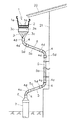
図1に示すサイホン式雨水排水装置は、底部に複数のサイホン管路1aを設けた軒樋1と、複数の縦サイホン管路を形成する上合2、捻じり継手3、エルボ継手4、堅樋部材5などの主要部品によって構成されている。これらの部品はいずれも、ポリカーボネート、ポリ塩化ビニル、ポリオレフィンなどの熱可塑性合成樹脂で押出成形あるいは射出成形されたものである。
【0016】
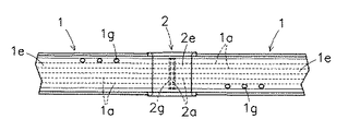
上記の軒樋1は、図3に示すように、上端に耳部1bを有する前板1cと後板1dを二重構造の底部1eの前縁と後縁からそれぞれ立設したものであって、二重構造の底部1eは数枚の仕切り板1fで幅方向に仕切られ、それによって略正方形の開口断面形状を有する複数のサイホン管路1aが軒樋底部1eの全長に亘って並列に形成されている。
【0017】
図2に示すように、この軒樋1の底部1eは長手方向にサイホン管路1aと同数の吸水ゾーンZに区画され、各サイホン管路1aに通じる吸水口1gが各サイホン管路1aに対応する吸水ゾーンZに複数個ずつ穿設されている。従って、家屋の屋根20から軒樋1に流れ込んだ雨水がそれぞれの吸水ゾーンZの吸水口1gからほぼ均等に吸水されるため、軒樋全長に亘って水位がほぼ一定となり、部分的に水位の高いところから雨水が溢れ出すことはない。
【0018】
この実施形態の軒樋1では、軒樋底部1eに6本のサイホン管路1aを設け、軒樋底部1eを長手方向に6つの吸水ゾーンZに区画しているが、サイホン管路1aの本数は6本より多くても少なくてもよく、そのサイホン管路1aの本数に合わせて吸水ゾーンZの数を増減すればよい。また、この軒樋1では、各サイホン管路1aに通じる吸水口1gを各吸水ゾーンZに3つずつ穿設しているが、吸水口1gの数はこれより多くても少なくてもよく、その形状も制限されない。
【0019】
サイホン管路1aの開口断面形状は、この実施形態のような略正方形に限定されるものではなく、長方形、円形、楕円形など種々の形状となしうるものであるが、いずれの開口断面形状の場合でも、良好なサイホン作用を発揮させるためにその開口面積を2〜20cm2の範囲に設定することが望ましい。従って、この実施形態のサイホン管路1aのように開口断面形状が略正方形である場合は、その一辺の長さを略1.4〜4.5cm程度とすることが好ましく、また、サイホン管路の開口断面形状が円形である場合は、その直径を1.5〜5.0cm程度とすることが好ましい。サイホン管路1aの開口面積が20cm2よりも大きくなると、既述したように、大雨のときでもサイホン管路内が雨水で満たされ難いためサイホン作用を発揮できない恐れが生じ、一方、開口面積が2cm2よりも小さくなると、ゴミ等の固形物が管路1a内に詰まりやすくなる。開口面積の好ましい範囲は3〜10cm2であり、このような小さい開口面積であると、サイホン管路1aの縦辺を短くできて軒樋1の体裁を保つことができる。また、後述する捻じり継手3、エルボ継手4、堅樋部材5においても奥行幅を短くでき、薄い継手や堅樋部材とすることができる。そのため、外壁材からの突出を少なくすることができ、家屋の外観を良くすることができるし、外壁材と内壁材との中空部にも配置しやすくなる。
【0020】
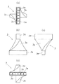
上記の上合2は、図6、図7に示すように、上端に耳部2bを有する前板2cと後板2dを底部2eの前縁と後縁から立設したもので、この上合2の長手方向両端には、軒樋1を接続するための軒樋嵌合部2f,2fが軒樋1の肉厚分だけ外側に膨出して形成されており、上記耳部2bの両端部は、接続される軒樋1の耳部1bを押える耳押えになっている。
【0021】
両端の軒樋嵌合部2b,2bの間の底部2eは二重構造とされ、この底部2eの長手方向中央から下方に向かって長方形の差込み口2gが突設されている。この二重構造の底部2eと差込み口2gはT形に連通しており、図7(b)に示すように仕切り板2hで幅方向に仕切ることによって、図7(a)に示すようなサイホンT形合流管路2aが前記軒樋底部のサイホン管路1aと同じ数(この実施形態では6つ)だけ並列に形成されている。このサイホンT形合流管路2aの両端開口の形状及び大きさは前記軒樋底部のサイホン管路1aの端部開口の形状及び大きさと同一であり、従って、図4、図5,図8に示すように前記軒樋1を左右から上合2の軒樋嵌合部2f,2fの内側に嵌合して接続すると、軒樋底部の各サイホン管路1aと上合2の各サイホンT形合流管路2aが連通するようになっている。
【0022】
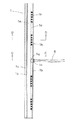
また、上記の捻じり継手3は、図8、図9に示すように、90°捻じられた長方形の開口断面形状を有する短筒体3bの内部を捻じり仕切り板3cで仕切ることにより、略正方形の開口断面形状を有する90°捻じられたサイホン短管路3aを前記軒樋底部のサイホン管路1aと同じ数(この実施形態では6本)だけ並列に形成したものであって、短筒体3bの上端には前記上合2の差込み口2gを接続するための長方形の受け口3dが一体に形成されており、短筒体3bの下端部はエルボ継手4に差込み接続するための差込み口3eとなっている。
【0023】
サイホン短管路3aの上下両端の開口の形状及び大きさは、前記上合2のサイホンT形合流管路2aの下端開口の形状及び大きさと同一であり、従って、図8に示すように上合2の差込み口2gを捻じり継手3の受け口3dに差し込んで接続すると、上合2の各サイホンT形合流管路2aと捻じり継手3の各サイホン短管路3aが連通するようになっている。このように上合2と捻じり継手3を接続すると、管路の並列方向が90°転換されて家屋の外壁と平行になるので、外壁からの突出寸法を小さくすることができる。
【0024】
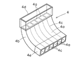
エルボ継手4は、図10に示すように、長方形の開口断面形状を有する湾曲筒体4bの内部を湾曲仕切り板4cで仕切ることにより、略正方形の開口断面形状を有するサイホン曲管路4aを前記軒樋底部のサイホン管路1aと同じ数(この実施形態では6本)だけ並列に形成したものであって、湾曲筒体4bの上端には前記捻じり継手3の差込み口3eを接続するための長方形の受け口4dが一体に形成されており、湾曲筒体4bの下端部は樋部材5に差込み接続するための差込み口4eとなっている。
【0025】
サイホン曲管路4aの上下両端の開口の形状及び大きさは、前記捻じり継手3のサイホン短管路3aの下端開口の形状及び大きさと同一であり、従って、図1に示すように捻じり継手3の下端の差込み口をエルボ継手4の上端の受け口4dに差し込んで接続すると、捻じり継手3の各サイホン短管路3aとエルボ継手4の各サイホン曲管路4aが連通するようになっている。
【0026】
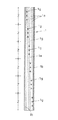
堅樋部材5は、図11に示すように、長方形の開口断面形状を有する直筒体5bの内部を仕切り板5cで仕切ることにより、略正方形の開口断面形状を有するサイホン直管路5aを前記軒樋底部のサイホン管路1aと同じ数(この実施形態では6本)だけ並列に形成したものであって、直筒体5bの上端には前記エルボ継手4の差込み口4eを接続するための長方形の受け口5dが一体に形成されており、直筒体5bの下端部はエルボ継手4の受け口4dに差込みできるようになっている。
【0027】
サイホン直管路5aの上下両端の開口の形状及び大きさは、前記エルボ継手4のサイホン曲管路3aの下端開口の形状及び大きさと同一であり、従って、図1に示すようにエルボ継手4の下端の差込み口を堅樋部材5の上端の受け口5dに差し込んで接続すると、エルボ継手4の各サイホン曲管路4aと樋部材5の各サイホン直管路5aが連通するようになっている。
【0028】
図1に示すサイホン式雨水排水装置は、上合2の差込み口2gを捻じり継手3の上端の受け口3dに差込み接続し、捻じり継手3の下端の差込み口3eをエルボ継手4の上端の受け口4dに差込み接続し、エルボ継手4の下端の差込み口4eを堅樋部材5の上端の受け口5dに差込み接続し、さらにエルボ継手4と堅樋部材5を交互に差込み接続することによって、上合2のサイホンT形合流管路2a、捻じり継手3のサイホン短管路3a、エルボ継手4のサイホン曲管路4a、堅樋部材5のサイホン直管路5aを連通させると共に、さらにエルボ継手4のサイホン曲管路4aと堅樋部材5のサイホン直管路5aを交互に連通させ、家屋の外壁材21に沿って軒樋底部のサイホン管路1aと同数(6本)の縦サイホン管路を並列に設けている。そして、軒樋1を上合2の軒樋嵌合部2f,2fに左右から嵌合、接続することによって、軒樋底部の6本のサイホン管路1aと上記の6本の縦サイホン管路を連通させて接続している。この縦サイホン管路の下端に位置するエルボ継手4は、変換継手6を介して円形の排水管7に接続され、この排水管7は地中の雨水ます(不図示)に接続されている。これらの各部材の差込み接続は、いずれも接着剤を塗布して気密的に行われることは言うまでもない。
【0029】
上記の変換継手6は、図12に示すように、エルボ継手の下端の差込み口が差し込まれる長方形の受け口6aを上端に設け、円形排水管7が差込み接続される円形の接続口6bを下端に設けたものである。
【0030】
以上のような構成のサイホン式雨水排水装置は、小雨のときには、屋根20から軒樋1に流れ込んだ雨水が軒樋底部1eの各吸水ゾーンZの吸水口1gからそれぞれのサイホン管路1aに流入して、それぞれの縦サイホン管路内を自然落下し、円形排水管7を通って排水される。
【0031】
一方、大雨のときには、軒樋底部の吸水口1gからサイホン管路1aへの流入量が増加し、軒樋底部のサイホン管路1aと縦サイホン管路が雨水で満たされると、吸水口1gと縦サイホン管路の下端との間に圧力差が生じ、サイホン作用によって雨水が吸水口1gから吸い込まれて自然落下排水の数倍の流速で軒樋底部のサイホン管路1aと縦サイホン管路を流れ落ち、多量の雨水が極めて効率良く排水される。例えば、軒樋底部のサイホン管路1aと縦サイホン管路の開口面積が略3cm2、吸水口1gと縦サイホン管路の下端までの高低差が略3mであると、雨水の流速は略1.7m/秒程度になり、6本のサイホン管路1aと6本の縦サイホン管路で排水できる雨量は略3リットル/秒程度になる。
【0032】
このようにサイホン式雨水排水装置は排水効率が極めて高く、しかも、軒樋1の各吸水ゾーンZの吸水口1gから雨水が略均等に吸水されて軒樋1内部の水位が略一定となるため、軒樋1を従来より小型化することが可能になる。そして、上合2,捻じり継手3、エルボ継手4、堅樋部材5を組み合わせて接続することにより設けられる縦サイホン管路の相互間隔も、従来の堅樋間隔より広げることが可能となるので、縦サイホン管路の設置数が少なくなり、コストアップや家屋の美観低下を防止することができる。
【0033】
なお、雨水の流速が上記のように速いため、軒樋底部のサイホン管路1aや縦サイホン管路にゴミなどの固形物は詰まりにくいが、場合によっては軒樋底部の吸水口1gにゴミ除けカバーなどを被着して、ゴミ詰まりをより確実に防止するようにしてもよい。
【0034】
また、上述したサイホン式雨水排水装置は、軒樋1の底部1eにサイホン管路1aを並列させて一段だけ設けているが、場合によっては、サイホン管路1aを並列させて上下二段に重ねて設けてもよい。その場合は、上合2のサイホンT形合流管路2a、捻じり継手3のサイホン短管路3a、エルボ継手4のサイホン曲管路4a、堅樋部材5のサイホン直管路5aを、いずれも並列させて二段に重ねて設け、これらを組合わせて接続したとき、並列して二段に重なった縦サイホン管路が形成されるようにする必要がある。
【0035】
図13は本発明の他の実施形態に係るサイホン式雨水排水装置の全体図、図14は同装置の軒樋の平面図、図15は図14のC−C線拡大断面図、図16は図14のC−C線拡大分解断面図、図17は同軒樋の拡大部分平面図、図18は図14のD−D線拡大断面図、図19は図14のD−D線拡大分解断面図、図20は同装置の水切りリングの斜視図である。
【0036】
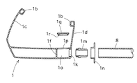
図13に示すサイホン式雨水排水装置は、軒樋底部に単数のサイホン管路1aを設けた軒樋1、縦サイホン管路となる可撓性のサイホンチューブ8などの主要部品によって構成されている。
【0037】
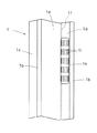
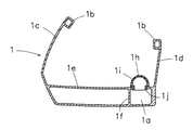
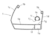
この軒樋1は、図15、図16に示すように、上端に耳部1bを有する前板1cと後板1dを二重構造の底部1eの前縁と後縁からそれぞれ立設したものであって、二重構造の底部1eは1枚の仕切り板1fで仕切られ、それによって略正方形の開口断面形状を有する一本のサイホン管路1aが軒樋底部1eの後縁沿いに全長に亘って形成されている。このサイホン管路1aの開口面積は、前記実施形態における軒樋底部のサイホン管路と同様に2〜20cm2,好ましくは3〜10cm2に設定すれば良好なサイホン作用を発揮できる。
【0038】
図14、図18、図19に示すように、サイホン管路1aの上面には、矩形の吸水口1gが長手方向に間隔をあけて複数形成されており、各吸水口1gには合成樹脂製のドーム形のゴミ除けカバー1hが取付けられている。吸水口1gの位置は、サイホンチューブ8の接続箇所から長手方向にずれていることが必要であり、このように吸水口1gの位置がずれていると空気を吸い込んでサイホン作用が停止する心配がなくなる。
【0039】
ゴミ除けカバー1hは、図17、図19に示すように、多数のスリット1iが形成されたドーム形の本体の下端に矩形の差込み口1jを形成したもので、この差込み口1jが矩形の吸水口1gに嵌合されて取付けられている。この差込み口1jの下端には戻り防止爪が形成されているため、上記のように吸水口1gに嵌合して取付けると、簡単に外れることはない。このようにゴミ除けカバー1hを取付けると、雨水のみがスリット1iから吸い込まれ、ゴミその他の固形物が除去されるので、サイホン管路1aやサイホンチューブ8のゴミ詰まりをより確実に防止することができる。
【0040】
軒樋底部1eの上面は、その前縁側から後縁側に向かって高さが徐々に低くなるように若干傾斜し、軒樋1内部に流入した雨水が吸水口1gから残らずサイホン管路1a内へ流れ込むようになっている。軒樋の底部1eに雨水が残っていると、上階から見下ろしたときの外観が悪くなるが、上記のように雨水が残らずサイホン管路1a内へ流れ込むと良好な外観を保つことができる。
【0041】
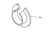
サイホンチューブ8の接続箇所は、図15,図16に示すように、軒樋底部の厚肉の後板1dに後方から孔1kを開けてタップを切り、先端に雄ネジを形成したねじ込みソケット1mを上記の孔1kにねじ込んで、サイホンチューブ8の端部をねじ込みソケット1mに嵌合接続すると共に、水切り部材1nをサイホンチューブ8に外嵌着した構造となっている。この水切り部材1nは、図20に示すように、一部が切欠された開環状に形成されており、サイホンチューブ8をねじ込みソケット1m嵌合接続した後から該チューブ8に外嵌着できるようになっている。なお、孔1kにタップを予め切らないで、ねじ込みソケット1mでタップを切りながらねじ込むようにしてもよい。
【0042】
図14、図15、図16に示すように、サイホン管路1aのサイホンチューブ接続箇所の上面には長方形の掃除口1pが設けられ、該掃除口1pに長方形のキャップ1qが被着されている。このキャップ1qはゴム製で、裏面に差込み口1rが形成されており、この差込み口1rを掃除口1pに嵌め込むことによって、気密的に且つ脱着自在に取付けられている。従って、このキャップ1qを取り外して線状の掃除具等を掃除口1pから挿入することにより、サイホンチューブ8や軒樋底部のサイホン管路1aを容易に清掃することが可能である。
【0043】
縦サイホン管路となるサイホンチューブ8は、軟質合成樹脂や合成ゴムなどからなる可撓性を有するチューブであって、図13に示すように、このサイホンチューブ8は軒先の破風板22を貫通して軒天23の裏側から、家屋外壁材21とその裏側の内壁材24との中空部25を通って、屋外の地中の雨水ます26に接続されている。従って、サイホンチューブ8が家屋の外側に露出しないので、家屋の美観を向上させることができる。
【0044】
上記ようにサイホンチューブ8を家屋外壁材21と内壁材24との中空部25に通しても、水切り部材1nによって雨水が水切りされ、軒天23の裏側への雨水の侵入が防止されるので問題は生じない。特に、サイホンチューブ8を通す破風板22の孔を塞ぐように水切り部材1nを取付け固定すると、より確実に雨水の侵入を防止することができる。また、サイホンチューブ8は、家屋外壁材21に近づけて中空部25を通すことが望ましく、そのようにすると、サイホンチューブ8を取りまく空気の温度と外気温との温度差が小さくなるため、サイホンチューブ8内を雨水が流下しても結露が生じ難くなる。また、サイホンチューブ8の下端を雨水ます26に接続しないで、雨水浸透トレンチ管(不図示)などに接続しても勿論よい。更に、上記のサイホンチューブ8と、別の軒樋からのサイホンチューブ8を一緒に一つの雨水ます26に接続してもよく、このように複数のサイホンチューブ8を一つの雨水ます26に接続すると、雨水ます26の数を少なくして排水管の施工などを少なくできる。
【0045】
なお、図13において、27は家屋外壁材21と内壁材24との中空部25に充填された断熱材である。
【0046】
以上のような構成のサイホン式雨水排水装置は、小雨のときには、屋根20から軒樋1に流れ込んだ雨水がゴミ除けカバー1hを通過して軒樋底部1eの各吸水口1gからサイホン管路1aに流入し、サイホンチューブ8内を自然落下して排水される。そして、大雨のときにサイホン管路1aへの流入量が増加し、該サイホン管路1aとサイホンチューブ8が雨水で満たされると、サイホン作用によって雨水が自然落下排水の数倍の流速でサイホン管路1aとサイホンチューブ8を流れ落ち、多量の雨水が極めて効率良く排水される。特に、このサイホン式雨水排水装置は、サイホンチューブ8の上端と下端との高低差が大きくて雨水の流速が速いため、サイホン管路1aとサイホンチューブ8が一本ずつでも、排水能力は十分である。
【0047】
しかも、サイホンチューブ8が屋外に露出しないので外観が向上し、また、サイホンチューブ8を配設するだけで簡単に縦サイホン管路を形成できるため施工性が良く、コストの一層の低減を実現することができる。
【0048】
この実施形態では、サイホンチューブ8として可撓性チューブを用いたが、硬質管を使用してもよい。さらに、軒樋1の後板に孔を開けたが、軒樋底部のサイホン管路1aの下面に開孔して、該底部開孔にねじ込みソケット1mをねじ込んでこれに可撓性チューブや硬質管を接続し、外壁材21の外面又は内面に沿わせて配設してもよい。
【0049】
図21は本発明の更に他の実施形態に係るサイホン式雨水排水装置の要部断面図である。
【0050】
このサイホン式雨水排水装置は、軒樋1の底部1eを二重構造としないで単層構造とし、この底部1eの後縁沿いの下面に一本のサイホン管路1aを形成している。その他の構成は前述した図13のサイホン式雨水排水装置と同様であるので、図21において同一部材に同一符号を付すにとどめ、説明は省略する。
【0051】
このようなサイホン式雨水排水装置も、前述のサイホン式雨水排水装置と同様の作用効果を奏することは言うまでもない。
【0052】
【発明の効果】
以上の説明から明らかなように、本発明のサイホン式雨水排水装置は、大雨になるとサイホン作用によって大量の雨水を極めて効率よく排水することができ、しかも、軒樋の小型化が可能である上に、縦サイホン管路の配設間隔を広げたり、縦サイホン管路を見えないように家屋外壁材の裏側に配設することが可能であるため、家屋の外観を向上させることができると共に、施工費用の低減を図ることもできるといった効果を奏する。
【図面の簡単な説明】
【図1】図1は本発明の一実施形態に係るサイホン式雨水排水装置の全体図である。
【図2】同装置の軒樋の平面図である。
【図3】同軒樋の横断面図である。
【図4】同装置の上合と軒樋との接続部分を示す平面図である。
【図5】同接続部分の正面図である。
【図6】同上合の斜視図である。
【図7】(a)は図6のA−A線断面図、(b)は図6のB−B線断面図である。
【図8】同装置の軒樋と上合と捻じり継手とエルボ継手を接続した部分の正面図である。
【図9】同捻じり継手を示すもので(a)は平面図、(b)は正面図、(c)は右側面図、(d)は底面図である。
【図10】同エルボ継手の斜視図である。
【図11】同装置の樋部材の斜視図である。
【図12】同装置の変換継手の斜視図である。
【図13】本発明の他の実施形態に係るサイホン式雨水排水装置の全体図である。
【図14】同装置の軒樋の平面図である。
【図15】図14のC−C線拡大断面図である。
【図16】図14のC−C線拡大分解断面図である。
【図17】同軒樋の拡大部分平面図である。
【図18】図14のD−D線拡大断面図である。
【図19】図14のD−D線拡大分解断面図である。
【図20】同装置の水切りリングの斜視図である。
【図21】本発明の更に他の実施形態に係るサイホン式雨水排水装置の要部断面図である。
【符号の説明】
1 軒樋
1a サイホン管路
1e 軒樋底部
1g 吸水口
1h ゴミ除けカバー
1p 掃除口
1q キャップ
Z 吸水ゾーン
2 上合
2a サイホンT形合流管路
3 捻じり継手
3a サイホン短管路
4 エルボ継手
4a サイホン曲管路
5 堅樋部材
5a サイホン直管路
8 サイホンチューブ
21 家屋外壁材
23 軒天
24 内壁材
25 中空部
26 雨水ます[0001]
TECHNICAL FIELD OF THE INVENTION
The present invention relates to a siphon-type rainwater drainage device that can drain rainwater extremely efficiently during heavy rain.
[0002]
[Prior art]
In a conventional house, an eaves gutter was attached to the eaves so as to have a flow gradient toward the kamigo (collector), and the rainwater flowing into the kamigo was naturally dropped through a hard gutter to drain water. However, because the appearance of the house is not good if the eaves gutter has a flow gradient, modern houses are increasingly mounting the eaves gutter horizontally without a flow gradient.
[0003]
[Problems to be solved by the invention]
However, the drainage system that collects rainwater at the eaves gutter and falls naturally inside the hard gutter as in the past is not very efficient in drainage, especially when the eaves gutter is installed horizontally. The further away, the lower the drainage efficiency and the higher the water level inside the eaves gutter. For this reason, it is necessary to install a large eaves gutter larger than the originally required capacity, or to reduce the interval between the upper and lower claddings, which leads to an increase in cost, and the appearance of the house is impaired due to an increase in the number of claddings and hard gutters. There was a problem.
[0004]
The present invention has been made in order to address the above-described problems, and has an object to be able to drain a large amount of rainwater extremely efficiently by a siphon action during heavy rain, without increasing the cost or impairing the appearance of a house. An object of the present invention is to provide a siphon type rainwater drainage device.
[0005]
[Means for Solving the Problems]
In order to achieve the above object, the siphon type rainwater drainage device according to the present invention is configured such that a siphon conduit is provided at the bottom of the eaves gutter over the entire length of the eaves gutter, and a water intake opening from the inside of the eaves gutter to the siphon conduit is provided. It is characterized in that the upper end of a vertical siphon pipe provided vertically along the outer wall material of the house is connected to the siphon pipe of the eaves gutter.
[0006]
In such a siphon type rainwater drainage system, in the case of light rain, rainwater flowing from the roof into the eaves gutter flows into the siphon pipeline from the water intake at the bottom of the eaves gutter, and falls naturally in the vertical siphon pipeline to be drained. . During heavy rain, the amount of inflow from the water intake to the siphon conduit at the bottom of the eaves gutter increases, and when the siphon conduit and the vertical siphon conduit at the bottom of the eaves gutter are filled with rainwater, the siphon action causes the rainwater to flow into the water intake. It is sucked from the water and flows down the siphon pipe and the vertical siphon pipe at the bottom of the eaves gutter at a flow rate several times that of the natural drainage, and a large amount of rainwater is drained extremely efficiently. Therefore, the siphon type rainwater drainage device of the present invention can use a smaller eaves gutter than the conventional one, and the interval between the connecting points of the vertical siphon conduits is wider than the conventional solid gutter interval to form the vertical siphon conduits. Since the number of connection points can be reduced, there is no need to increase the cost or spoil the appearance of the house.
[0007]
In the siphon type rainwater drainage device of the present invention, the opening area of the siphon pipe at the bottom of the eaves gutter or the vertical siphon pipe along the outer wall material is 2 to 20 cm. 2 It is preferable to set the opening area so that a good siphon action is exhibited. Opening area is 20cm 2 If it becomes larger, it becomes difficult for the siphon pipeline and the vertical siphon pipeline at the bottom of the eaves gutter to be filled with rainwater even in the case of heavy rain.
Since the flow rate of rainwater flowing through these pipes by the siphon action is high, even if the opening area of these pipes is small to a certain extent, dust and other solid matter will not be washed out and clogged in the pipes, but Opening area is 2cm 2 If the size is smaller, dust and the like are likely to be clogged.
[0008]
In the siphonic rainwater drainage device of the present invention, it is preferable to attach a dust cover to the water inlet, and in this way, it is possible to more reliably prevent clogging of the siphon pipeline and the vertical siphon pipeline at the bottom of the eaves gutter. Can be.
[0009]
In the siphon type rainwater drainage device of the present invention, a plurality of siphon conduits are provided in parallel at the bottom of the eaves gutter, and the eaves gutter is divided into the same number of water absorption zones as the siphon conduits over the entire length, and each siphon conduit is provided with a siphon conduit. Is preferably provided in a water absorption zone corresponding to each siphon pipe. In this way, the rainwater flowing into the eaves gutter from the roof of the house can be almost uniformly absorbed into the siphon conduit from the water intakes of the respective evacuation zones of the eaves gutter, so that the water level is almost constant over the entire length of the eaves gutter. Become. Accordingly, since the water level does not partially rise and rainwater does not overflow from the eaves gutter, a small eaves gutter can be used.
[0010]
When a plurality of siphon conduits are provided at the bottom of the eaves gutter as described above, the same number of siphon T-type merging conduits as the siphon conduits at the bottom of the eaves gutter are formed in parallel with the siphon at the bottom of the eaves gutter. A torsion joint formed by twisting the same number of siphon short pipes in parallel and 90 ° as the pipes, an elbow joint formed in parallel with the same number of siphon bent pipes as the siphon pipes at the bottom of the eaves gutter, and an eaves gutter By combining the bottom siphon pipeline and the same number of siphon straight pipes in parallel with the hard gutter members formed in parallel, the same number of vertical siphon pipelines as the siphon pipeline at the bottom of the eaves gutter are provided. Preferably, each longitudinal siphon line is connected to a respective siphon line at the bottom of the eaves gutter by connecting an eaves gutter.
[0011]
Further, the siphon type rainwater drainage device of the present invention provides a single siphon conduit at the bottom of the eaves gutter, and connects the upper end of a flexible siphon tube serving as a vertical siphon conduit to the siphon conduit at the bottom of the eaves gutter. However, it is also preferable to adopt a configuration in which the position of the water intake port is shifted from the connection point of the siphon tube to both longitudinal sides of the eaves gutter. In this way, a flexible vertical siphon pipe can be easily formed, and furthermore, since the position of the water intake port is displaced from the connection point of the siphon tube, the fear that the siphon action stops due to the inhalation of air is also eliminated.
[0012]
When a single siphon pipe is provided at the bottom of the eaves gutter and a siphon tube is connected as described above, a cleaning port is formed on the upper surface of the siphon tube connection point of the siphon pipe, and a cap is attached to and removed from the cleaning port. It is preferable to attach the siphon tube freely, and it is also preferable to connect the siphon tube from the back of the eaves to the underground rainwater trough through the hollow portion with the inner wall material on the back side of the house outdoor wall material. By doing so, it is possible to remove the cap from the cleaning port and easily clean the siphon tube and the siphon conduit at the bottom of the eaves gutter with a linear cleaning tool. Can be improved in appearance.
[0013]
BEST MODE FOR CARRYING OUT THE INVENTION
Hereinafter, embodiments of the present invention will be described in detail with reference to the drawings.
[0014]
1 is an overall view of a siphon type rainwater drainage device according to one embodiment of the present invention, FIG. 2 is a plan view of an eaves gutter of the device, FIG. 3 is a cross-sectional view of the eaves gutter, and FIG. FIG. 5 is a plan view showing a connection portion between the joint and the eave gutter, FIG. 5 is a front view of the connection portion, FIG. 6 is a perspective view of the same connection, FIG. 7A is a cross-sectional view taken along line AA of FIG. (B) is a cross-sectional view taken along the line BB in FIG. 6, FIG. 8 is a front view of a portion where the eaves gutter, the upper joint, the torsion joint, and the elbow joint are connected, and FIG. 9 shows the torsion joint. (A) is a plan view, (b) is a front view, (c) is a right side view, (d) is a bottom view, FIG. 10 is a perspective view of the elbow joint, and FIG. FIG. 12 is a perspective view of a conversion joint of the apparatus.
[0015]
The siphon type rainwater drainage device shown in FIG. 1 has an
[0016]
As shown in FIG. 3, the
[0017]
As shown in FIG. 2, the bottom 1e of the
[0018]
In the
[0019]
The cross-sectional shape of the opening of the siphon
[0020]
As shown in FIGS. 6 and 7, the
[0021]
A
[0022]
As shown in FIGS. 8 and 9, the
[0023]
The shape and size of the openings at the upper and lower ends of the short siphon
[0024]
As shown in FIG. 10, the
[0025]
The shape and size of the opening at the upper and lower ends of the siphon bent pipe 4a are the same as the shape and size of the lower end opening of the siphon
[0026]
As shown in FIG. 11, the
[0027]
The shape and size of the openings at the upper and lower ends of the siphon straight pipe 5a are the same as the shape and size of the lower end opening of the siphon
[0028]
In the siphon type rainwater drainage device shown in FIG. 1, the
[0029]
As shown in FIG. 12, the conversion joint 6 has a rectangular receiving
[0030]
In the siphon type rainwater drainage device configured as described above, in the case of light rain, the rainwater flowing into the
[0031]
On the other hand, during heavy rain, the amount of water flowing into the siphon
[0032]
As described above, the siphon type rainwater drainage device has extremely high drainage efficiency, and furthermore, rainwater is almost uniformly absorbed from the water inlet 1g of each water absorption zone Z of the
[0033]
Since the flow rate of rainwater is high as described above, solids such as dust are hardly clogged in the siphon
[0034]
Further, in the above-mentioned siphon type rainwater drainage device, the siphon
[0035]
13 is an overall view of a siphon type rainwater drainage device according to another embodiment of the present invention, FIG. 14 is a plan view of an eaves gutter of the device, FIG. 15 is an enlarged cross-sectional view taken along line CC of FIG. 14, and FIG. Fig. 17 is an enlarged partial plan view of the eaves gutter, Fig. 18 is an enlarged sectional view taken along line DD of Fig. 14, and Fig. 19 is an enlarged exploded sectional view of Fig. 14. FIG. 20 is a perspective view of a draining ring of the device.
[0036]
The siphon type rainwater drainage device shown in FIG. 13 is composed of main parts such as an
[0037]
As shown in FIGS. 15 and 16, the
[0038]
As shown in FIGS. 14, 18, and 19, a plurality of rectangular water inlets 1g are formed on the upper surface of the siphon
[0039]
As shown in FIG. 17 and FIG. 19, the
[0040]
The upper surface of the
[0041]
As shown in FIGS. 15 and 16, the connection point of the siphon
[0042]
As shown in FIGS. 14, 15 and 16, a
[0043]
The siphon
[0044]
Even if the siphon
[0045]
In FIG. 13,
[0046]
In the siphon type rainwater drainage device configured as described above, in the case of light rain, the rainwater flowing into the
[0047]
Moreover, the appearance is improved because the siphon
[0048]
In this embodiment, a flexible tube is used as the siphon
[0049]
FIG. 21 is a sectional view of a principal part of a siphon type rainwater drainage device according to still another embodiment of the present invention.
[0050]
In this siphon type rainwater drainage device, the bottom 1e of the
[0051]
Needless to say, such a siphon type rainwater drainage device also has the same operation and effect as the above-described siphon type rainwater drainage device.
[0052]
【The invention's effect】
As is clear from the above description, the siphon type rainwater drainage device of the present invention can drain a large amount of rainwater extremely efficiently by the siphon action when heavy rain occurs, and furthermore, the eaves gutter can be downsized. In addition, since it is possible to increase the interval between the vertical siphon pipes and to dispose the vertical siphon pipe behind the wall material outside the house so that the vertical siphon pipes are not visible, it is possible to improve the appearance of the house, This has the effect of reducing the construction cost.
[Brief description of the drawings]
FIG. 1 is an overall view of a siphon type rainwater drainage device according to one embodiment of the present invention.
FIG. 2 is a plan view of an eaves gutter of the apparatus.
FIG. 3 is a cross-sectional view of the eaves gutter.
FIG. 4 is a plan view showing a connecting portion between the upper part and the eave gutter of the same device.
FIG. 5 is a front view of the connection portion.
FIG. 6 is a perspective view of the same.
7A is a sectional view taken along line AA of FIG. 6, and FIG. 7B is a sectional view taken along line BB of FIG.
FIG. 8 is a front view of a part where the eaves gutter, the upper joint, the torsion joint, and the elbow joint of the apparatus are connected.
9 (a) is a plan view, FIG. 9 (b) is a front view, FIG. 9 (c) is a right side view, and FIG. 9 (d) is a bottom view.
FIG. 10 is a perspective view of the elbow joint.
FIG. 11 is a perspective view of a gutter member of the apparatus.
FIG. 12 is a perspective view of a conversion joint of the device.
FIG. 13 is an overall view of a siphon type rainwater drainage device according to another embodiment of the present invention.
FIG. 14 is a plan view of an eaves gutter of the apparatus.
FIG. 15 is an enlarged sectional view taken along line CC of FIG. 14;
FIG. 16 is an enlarged exploded cross-sectional view taken along line CC of FIG. 14;
FIG. 17 is an enlarged partial plan view of the eaves gutter.
FIG. 18 is an enlarged sectional view taken along line DD of FIG. 14;
19 is an enlarged exploded sectional view taken along line DD of FIG.
FIG. 20 is a perspective view of a draining ring of the device.
FIG. 21 is a sectional view of a main part of a siphon type rainwater drainage device according to still another embodiment of the present invention.
[Explanation of symbols]
1 eave gutter
1a Siphon pipeline
1e eaves gutter bottom
1g water intake
1h Garbage cover
1p cleaning mouth
1q cap
Z water absorption zone
2 Jogo
2a Siphon T-shaped merging line
3 Torsion joint
3a Short siphon conduit
4 Elbow joint
4a Siphon curved pipe
5 Hard gutter members
5a Siphon straight pipe
8 siphon tube
21 House outdoor wall material
23 eaves
24 Interior wall materials
25 hollow
26 Rainwater
Claims (8)
Priority Applications (1)
| Application Number | Priority Date | Filing Date | Title |
|---|---|---|---|
| JP2003044928A JP4130595B2 (en) | 2003-02-21 | 2003-02-21 | Siphon rainwater drainage system |
Applications Claiming Priority (1)
| Application Number | Priority Date | Filing Date | Title |
|---|---|---|---|
| JP2003044928A JP4130595B2 (en) | 2003-02-21 | 2003-02-21 | Siphon rainwater drainage system |
Related Child Applications (1)
| Application Number | Title | Priority Date | Filing Date |
|---|---|---|---|
| JP2008068737A Division JP4603061B2 (en) | 2008-03-18 | 2008-03-18 | Siphon rainwater drainage system |
Publications (2)
| Publication Number | Publication Date |
|---|---|
| JP2004251075A true JP2004251075A (en) | 2004-09-09 |
| JP4130595B2 JP4130595B2 (en) | 2008-08-06 |
Family
ID=33027492
Family Applications (1)
| Application Number | Title | Priority Date | Filing Date |
|---|---|---|---|
| JP2003044928A Expired - Lifetime JP4130595B2 (en) | 2003-02-21 | 2003-02-21 | Siphon rainwater drainage system |
Country Status (1)
| Country | Link |
|---|---|
| JP (1) | JP4130595B2 (en) |
Cited By (9)
| Publication number | Priority date | Publication date | Assignee | Title |
|---|---|---|---|---|
| KR101036617B1 (en) * | 2007-10-02 | 2011-05-24 | 삼성엔지니어링 주식회사 | Rainwater drain apparatus having hydraulic rain leader pipe with built-in screw |
| JP2012132192A (en) * | 2010-12-21 | 2012-07-12 | Panasonic Corp | Rain gutter structure |
| WO2015120175A1 (en) * | 2014-02-05 | 2015-08-13 | Creation Enterprise, Inc. | Roof water conduit assemblies and methods |
| JP2016194214A (en) * | 2015-03-31 | 2016-11-17 | 積水化学工業株式会社 | Rainwater drainage system |
| JP2018003463A (en) * | 2016-07-04 | 2018-01-11 | 積水化学工業株式会社 | Air bleeder drain pipe cover and rainwater drainage system |
| JP2019120068A (en) * | 2018-01-09 | 2019-07-22 | 積水化学工業株式会社 | Elbow, and siphon rain gutter system |
| JP2021006704A (en) * | 2018-01-09 | 2021-01-21 | 積水化学工業株式会社 | Siphon rain gutter system and siphon drain member |
| JP2022040397A (en) * | 2021-07-21 | 2022-03-10 | 積水化学工業株式会社 | Siphon rain gutter system |
| JP7445585B2 (en) | 2020-12-03 | 2024-03-07 | 株式会社ブリヂストン | siphon drainage system |
-
2003
- 2003-02-21 JP JP2003044928A patent/JP4130595B2/en not_active Expired - Lifetime
Cited By (10)
| Publication number | Priority date | Publication date | Assignee | Title |
|---|---|---|---|---|
| KR101036617B1 (en) * | 2007-10-02 | 2011-05-24 | 삼성엔지니어링 주식회사 | Rainwater drain apparatus having hydraulic rain leader pipe with built-in screw |
| JP2012132192A (en) * | 2010-12-21 | 2012-07-12 | Panasonic Corp | Rain gutter structure |
| WO2015120175A1 (en) * | 2014-02-05 | 2015-08-13 | Creation Enterprise, Inc. | Roof water conduit assemblies and methods |
| JP2016194214A (en) * | 2015-03-31 | 2016-11-17 | 積水化学工業株式会社 | Rainwater drainage system |
| JP2018003463A (en) * | 2016-07-04 | 2018-01-11 | 積水化学工業株式会社 | Air bleeder drain pipe cover and rainwater drainage system |
| JP2019120068A (en) * | 2018-01-09 | 2019-07-22 | 積水化学工業株式会社 | Elbow, and siphon rain gutter system |
| JP2021006704A (en) * | 2018-01-09 | 2021-01-21 | 積水化学工業株式会社 | Siphon rain gutter system and siphon drain member |
| JP7445585B2 (en) | 2020-12-03 | 2024-03-07 | 株式会社ブリヂストン | siphon drainage system |
| JP2022040397A (en) * | 2021-07-21 | 2022-03-10 | 積水化学工業株式会社 | Siphon rain gutter system |
| JP7060770B2 (en) | 2021-07-21 | 2022-04-26 | 積水化学工業株式会社 | Siphon rain gutter system |
Also Published As
| Publication number | Publication date |
|---|---|
| JP4130595B2 (en) | 2008-08-06 |
Similar Documents
| Publication | Publication Date | Title |
|---|---|---|
| JP4130616B2 (en) | Siphon rainwater drainage system | |
| JP4603061B2 (en) | Siphon rainwater drainage system | |
| JP2004251075A (en) | Siphon type rainwater draining device | |
| JP7284778B2 (en) | Drainage members and rain gutters | |
| US6467995B2 (en) | Self-flushing pipe | |
| US5117597A (en) | Roof vent pipe collection device | |
| JP7356606B2 (en) | Rainwater basins and construction methods for rainwater basins | |
| JP4442749B2 (en) | Rainwater drainage structure | |
| JP2009155919A (en) | Rainwater storage device, foundation joint, and house with rainwater storage device | |
| JP4589656B2 (en) | Gutter device | |
| JP3652026B2 (en) | Eaves drainage structure of building | |
| CN2312256Y (en) | Water overflow means for washbasin | |
| KR200265310Y1 (en) | Sewage. Rainwater classification drain trap | |
| JP2000248588A (en) | Water collecting system | |
| CN218346354U (en) | Prevent stifled squatting pan blow off pipe with be suitable for multi-direction blowdown | |
| JP2006016780A (en) | Ventilation structure of underfloor piping | |
| JP3167565B2 (en) | Kitchen stand drain branch pipe | |
| JPH07292758A (en) | Synthetic resin made rainwater pit | |
| JPS6033244Y2 (en) | Gutter joint cap | |
| JP2006016779A (en) | Ventilation structure of underfloor piping | |
| JP2000291079A (en) | Leader water intake device | |
| JP2022077075A (en) | Rain gutter system | |
| KR20220154561A (en) | Apparatus for collecting rainfall | |
| JPH0419140Y2 (en) | ||
| JP2000248698A (en) | Water intake gutter joint and water collecting system |
Legal Events
| Date | Code | Title | Description |
|---|---|---|---|
| A621 | Written request for application examination |
Free format text: JAPANESE INTERMEDIATE CODE: A621 Effective date: 20060118 |
|
| A977 | Report on retrieval |
Free format text: JAPANESE INTERMEDIATE CODE: A971007 Effective date: 20080128 |
|
| A131 | Notification of reasons for refusal |
Free format text: JAPANESE INTERMEDIATE CODE: A131 Effective date: 20080206 |
|
| A521 | Request for written amendment filed |
Free format text: JAPANESE INTERMEDIATE CODE: A523 Effective date: 20080318 |
|
| TRDD | Decision of grant or rejection written | ||
| A01 | Written decision to grant a patent or to grant a registration (utility model) |
Free format text: JAPANESE INTERMEDIATE CODE: A01 Effective date: 20080423 |
|
| A01 | Written decision to grant a patent or to grant a registration (utility model) |
Free format text: JAPANESE INTERMEDIATE CODE: A01 |
|
| A61 | First payment of annual fees (during grant procedure) |
Free format text: JAPANESE INTERMEDIATE CODE: A61 Effective date: 20080522 |
|
| R150 | Certificate of patent or registration of utility model |
Ref document number: 4130595 Country of ref document: JP Free format text: JAPANESE INTERMEDIATE CODE: R150 Free format text: JAPANESE INTERMEDIATE CODE: R150 |
|
| FPAY | Renewal fee payment (event date is renewal date of database) |
Free format text: PAYMENT UNTIL: 20110530 Year of fee payment: 3 |
|
| FPAY | Renewal fee payment (event date is renewal date of database) |
Free format text: PAYMENT UNTIL: 20110530 Year of fee payment: 3 |
|
| FPAY | Renewal fee payment (event date is renewal date of database) |
Free format text: PAYMENT UNTIL: 20110530 Year of fee payment: 3 |
|
| FPAY | Renewal fee payment (event date is renewal date of database) |
Free format text: PAYMENT UNTIL: 20120530 Year of fee payment: 4 |
|
| R250 | Receipt of annual fees |
Free format text: JAPANESE INTERMEDIATE CODE: R250 |
|
| S531 | Written request for registration of change of domicile |
Free format text: JAPANESE INTERMEDIATE CODE: R313531 |
|
| FPAY | Renewal fee payment (event date is renewal date of database) |
Free format text: PAYMENT UNTIL: 20120530 Year of fee payment: 4 |
|
| R350 | Written notification of registration of transfer |
Free format text: JAPANESE INTERMEDIATE CODE: R350 |
|
| FPAY | Renewal fee payment (event date is renewal date of database) |
Free format text: PAYMENT UNTIL: 20120530 Year of fee payment: 4 |
|
| FPAY | Renewal fee payment (event date is renewal date of database) |
Free format text: PAYMENT UNTIL: 20130530 Year of fee payment: 5 |
|
| R250 | Receipt of annual fees |
Free format text: JAPANESE INTERMEDIATE CODE: R250 |
|
| FPAY | Renewal fee payment (event date is renewal date of database) |
Free format text: PAYMENT UNTIL: 20130530 Year of fee payment: 5 |
|
| R250 | Receipt of annual fees |
Free format text: JAPANESE INTERMEDIATE CODE: R250 |
|
| R250 | Receipt of annual fees |
Free format text: JAPANESE INTERMEDIATE CODE: R250 |
|
| R250 | Receipt of annual fees |
Free format text: JAPANESE INTERMEDIATE CODE: R250 |
|
| R250 | Receipt of annual fees |
Free format text: JAPANESE INTERMEDIATE CODE: R250 |
|
| R250 | Receipt of annual fees |
Free format text: JAPANESE INTERMEDIATE CODE: R250 |
|
| R250 | Receipt of annual fees |
Free format text: JAPANESE INTERMEDIATE CODE: R250 |
|
| S533 | Written request for registration of change of name |
Free format text: JAPANESE INTERMEDIATE CODE: R313533 |
|
| R350 | Written notification of registration of transfer |
Free format text: JAPANESE INTERMEDIATE CODE: R350 |
|
| R250 | Receipt of annual fees |
Free format text: JAPANESE INTERMEDIATE CODE: R250 |
|
| R250 | Receipt of annual fees |
Free format text: JAPANESE INTERMEDIATE CODE: R250 |
|
| R250 | Receipt of annual fees |
Free format text: JAPANESE INTERMEDIATE CODE: R250 |
|
| R250 | Receipt of annual fees |
Free format text: JAPANESE INTERMEDIATE CODE: R250 |
|
| EXPY | Cancellation because of completion of term |