JP2004249985A - Master cylinder for automobile having device for detecting actuation of braking system - Google Patents
Master cylinder for automobile having device for detecting actuation of braking system Download PDFInfo
- Publication number
- JP2004249985A JP2004249985A JP2004043940A JP2004043940A JP2004249985A JP 2004249985 A JP2004249985 A JP 2004249985A JP 2004043940 A JP2004043940 A JP 2004043940A JP 2004043940 A JP2004043940 A JP 2004043940A JP 2004249985 A JP2004249985 A JP 2004249985A
- Authority
- JP
- Japan
- Prior art keywords
- master cylinder
- pole piece
- magnetic circuit
- piston
- magnetic
- Prior art date
- Legal status (The legal status is an assumption and is not a legal conclusion. Google has not performed a legal analysis and makes no representation as to the accuracy of the status listed.)
- Pending
Links
Images


Classifications
-
- B—PERFORMING OPERATIONS; TRANSPORTING
- B60—VEHICLES IN GENERAL
- B60Q—ARRANGEMENT OF SIGNALLING OR LIGHTING DEVICES, THE MOUNTING OR SUPPORTING THEREOF OR CIRCUITS THEREFOR, FOR VEHICLES IN GENERAL
- B60Q1/00—Arrangement of optical signalling or lighting devices, the mounting or supporting thereof or circuits therefor
- B60Q1/26—Arrangement of optical signalling or lighting devices, the mounting or supporting thereof or circuits therefor the devices being primarily intended to indicate the vehicle, or parts thereof, or to give signals, to other traffic
- B60Q1/44—Arrangement of optical signalling or lighting devices, the mounting or supporting thereof or circuits therefor the devices being primarily intended to indicate the vehicle, or parts thereof, or to give signals, to other traffic for indicating braking action or preparation for braking, e.g. by detection of the foot approaching the brake pedal
- B60Q1/441—Electric switches operable by the driver's pedals
-
- B—PERFORMING OPERATIONS; TRANSPORTING
- B60—VEHICLES IN GENERAL
- B60T—VEHICLE BRAKE CONTROL SYSTEMS OR PARTS THEREOF; BRAKE CONTROL SYSTEMS OR PARTS THEREOF, IN GENERAL; ARRANGEMENT OF BRAKING ELEMENTS ON VEHICLES IN GENERAL; PORTABLE DEVICES FOR PREVENTING UNWANTED MOVEMENT OF VEHICLES; VEHICLE MODIFICATIONS TO FACILITATE COOLING OF BRAKES
- B60T11/00—Transmitting braking action from initiating means to ultimate brake actuator without power assistance or drive or where such assistance or drive is irrelevant
- B60T11/10—Transmitting braking action from initiating means to ultimate brake actuator without power assistance or drive or where such assistance or drive is irrelevant transmitting by fluid means, e.g. hydraulic
- B60T11/16—Master control, e.g. master cylinders
-
- B—PERFORMING OPERATIONS; TRANSPORTING
- B60—VEHICLES IN GENERAL
- B60T—VEHICLE BRAKE CONTROL SYSTEMS OR PARTS THEREOF; BRAKE CONTROL SYSTEMS OR PARTS THEREOF, IN GENERAL; ARRANGEMENT OF BRAKING ELEMENTS ON VEHICLES IN GENERAL; PORTABLE DEVICES FOR PREVENTING UNWANTED MOVEMENT OF VEHICLES; VEHICLE MODIFICATIONS TO FACILITATE COOLING OF BRAKES
- B60T17/00—Component parts, details, or accessories of power brake systems not covered by groups B60T8/00, B60T13/00 or B60T15/00, or presenting other characteristic features
- B60T17/18—Safety devices; Monitoring
- B60T17/22—Devices for monitoring or checking brake systems; Signal devices
-
- B—PERFORMING OPERATIONS; TRANSPORTING
- B60—VEHICLES IN GENERAL
- B60T—VEHICLE BRAKE CONTROL SYSTEMS OR PARTS THEREOF; BRAKE CONTROL SYSTEMS OR PARTS THEREOF, IN GENERAL; ARRANGEMENT OF BRAKING ELEMENTS ON VEHICLES IN GENERAL; PORTABLE DEVICES FOR PREVENTING UNWANTED MOVEMENT OF VEHICLES; VEHICLE MODIFICATIONS TO FACILITATE COOLING OF BRAKES
- B60T7/00—Brake-action initiating means
- B60T7/02—Brake-action initiating means for personal initiation
- B60T7/04—Brake-action initiating means for personal initiation foot actuated
- B60T7/042—Brake-action initiating means for personal initiation foot actuated by electrical means, e.g. using travel or force sensors
-
- F—MECHANICAL ENGINEERING; LIGHTING; HEATING; WEAPONS; BLASTING
- F15—FLUID-PRESSURE ACTUATORS; HYDRAULICS OR PNEUMATICS IN GENERAL
- F15B—SYSTEMS ACTING BY MEANS OF FLUIDS IN GENERAL; FLUID-PRESSURE ACTUATORS, e.g. SERVOMOTORS; DETAILS OF FLUID-PRESSURE SYSTEMS, NOT OTHERWISE PROVIDED FOR
- F15B15/00—Fluid-actuated devices for displacing a member from one position to another; Gearing associated therewith
- F15B15/20—Other details, e.g. assembly with regulating devices
- F15B15/28—Means for indicating the position, e.g. end of stroke
- F15B15/2807—Position switches, i.e. means for sensing of discrete positions only, e.g. limit switches
-
- G—PHYSICS
- G01—MEASURING; TESTING
- G01D—MEASURING NOT SPECIALLY ADAPTED FOR A SPECIFIC VARIABLE; ARRANGEMENTS FOR MEASURING TWO OR MORE VARIABLES NOT COVERED IN A SINGLE OTHER SUBCLASS; TARIFF METERING APPARATUS; MEASURING OR TESTING NOT OTHERWISE PROVIDED FOR
- G01D5/00—Mechanical means for transferring the output of a sensing member; Means for converting the output of a sensing member to another variable where the form or nature of the sensing member does not constrain the means for converting; Transducers not specially adapted for a specific variable
- G01D5/12—Mechanical means for transferring the output of a sensing member; Means for converting the output of a sensing member to another variable where the form or nature of the sensing member does not constrain the means for converting; Transducers not specially adapted for a specific variable using electric or magnetic means
- G01D5/14—Mechanical means for transferring the output of a sensing member; Means for converting the output of a sensing member to another variable where the form or nature of the sensing member does not constrain the means for converting; Transducers not specially adapted for a specific variable using electric or magnetic means influencing the magnitude of a current or voltage
- G01D5/142—Mechanical means for transferring the output of a sensing member; Means for converting the output of a sensing member to another variable where the form or nature of the sensing member does not constrain the means for converting; Transducers not specially adapted for a specific variable using electric or magnetic means influencing the magnitude of a current or voltage using Hall-effect devices
- G01D5/147—Mechanical means for transferring the output of a sensing member; Means for converting the output of a sensing member to another variable where the form or nature of the sensing member does not constrain the means for converting; Transducers not specially adapted for a specific variable using electric or magnetic means influencing the magnitude of a current or voltage using Hall-effect devices influenced by the movement of a third element, the position of Hall device and the source of magnetic field being fixed in respect to each other
-
- G—PHYSICS
- G01—MEASURING; TESTING
- G01D—MEASURING NOT SPECIALLY ADAPTED FOR A SPECIFIC VARIABLE; ARRANGEMENTS FOR MEASURING TWO OR MORE VARIABLES NOT COVERED IN A SINGLE OTHER SUBCLASS; TARIFF METERING APPARATUS; MEASURING OR TESTING NOT OTHERWISE PROVIDED FOR
- G01D5/00—Mechanical means for transferring the output of a sensing member; Means for converting the output of a sensing member to another variable where the form or nature of the sensing member does not constrain the means for converting; Transducers not specially adapted for a specific variable
- G01D5/12—Mechanical means for transferring the output of a sensing member; Means for converting the output of a sensing member to another variable where the form or nature of the sensing member does not constrain the means for converting; Transducers not specially adapted for a specific variable using electric or magnetic means
- G01D5/25—Selecting one or more conductors or channels from a plurality of conductors or channels, e.g. by closing contacts
- G01D5/251—Selecting one or more conductors or channels from a plurality of conductors or channels, e.g. by closing contacts one conductor or channel
- G01D5/2515—Selecting one or more conductors or channels from a plurality of conductors or channels, e.g. by closing contacts one conductor or channel with magnetically controlled switches, e.g. by movement of a magnet
-
- H—ELECTRICITY
- H01—ELECTRIC ELEMENTS
- H01H—ELECTRIC SWITCHES; RELAYS; SELECTORS; EMERGENCY PROTECTIVE DEVICES
- H01H36/00—Switches actuated by change of magnetic field or of electric field, e.g. by change of relative position of magnet and switch, by shielding
- H01H36/0006—Permanent magnet actuating reed switches
- H01H36/0013—Permanent magnet actuating reed switches characterised by the co-operation between reed switch and permanent magnet; Magnetic circuits
- H01H36/002—Actuation by moving ferromagnetic material, switch and magnet being fixed
-
- H—ELECTRICITY
- H01—ELECTRIC ELEMENTS
- H01H—ELECTRIC SWITCHES; RELAYS; SELECTORS; EMERGENCY PROTECTIVE DEVICES
- H01H36/00—Switches actuated by change of magnetic field or of electric field, e.g. by change of relative position of magnet and switch, by shielding
- H01H36/0006—Permanent magnet actuating reed switches
- H01H36/0046—Limit switches, also fail-safe operation or anti-tamper considerations
Abstract
Description
本発明の主題又は要旨は、制動システムの作動を検出するための装置を持つ自動車用マスターシリンダを提供することである。本発明は、更に詳細には、制動システムの作動を検出するためのこの装置をマスターシリンダに設けることに関する。 The subject or gist of the present invention is to provide a motor vehicle master cylinder having a device for detecting the operation of a braking system. The invention relates more particularly to the provision of this device on the master cylinder for detecting the operation of the braking system.
本発明の目的は、車輛の制動の検出が容易なシステムを提供することである。本発明の別の目的は、システムに作用を及ぼす必要があるときに運転者又は修理工が容易にアクセスできる制動検出システムを提案することである。本発明の更に別の目的は、エンジンルームでの占有空間が小さい、制動システムの作動を検出するための装置を含むマスターシリンダを提供することである。 SUMMARY OF THE INVENTION It is an object of the present invention to provide a system that facilitates detection of vehicle braking. Another object of the present invention is to propose a braking detection system that can be easily accessed by a driver or mechanic when the system needs to be affected. Still another object of the present invention is to provide a master cylinder including a device for detecting the operation of a braking system, which occupies a small space in an engine room.
一般的には、車輛の制動システムの作動を検出する装置は、ブレーキペダルの傍に配置される。このような検出システムは、とりわけ、車輛の制動灯の点灯及び消灯を行うのに役立つ。従って、これらの制動灯即ち停止灯は、早期に点灯される必要がある。即ち、車輛が最初に制動を開始すると直ぐに点灯される必要がある。 Typically, the device that detects the activation of the vehicle's braking system is located beside the brake pedal. Such a detection system is useful, inter alia, for turning on and off the brake lights of a vehicle. Therefore, these brake lights or stop lights need to be turned on early. That is, it must be turned on as soon as the vehicle first starts braking.
従来技術では、スイッチはブレーキペダルの近くに配置される。ブレーキペダルを踏み込むと、スイッチが作動され、制動灯を点灯する。スイッチとブレーキペダルが近接しているということは、制動灯を早期に点灯できるということを意味する。しかしながら、このような装置は、車室の特別の近づき難い位置にある。従って、故障した場合や単に検査が必要な場合には、装置にアクセスするのが困難である。更に、車室内の空間を考慮すると、装置の寸法の計算及び検査を非常に正確に行う必要がある。 In the prior art, the switch is located near the brake pedal. When the brake pedal is depressed, the switch is activated and the brake light is turned on. The proximity of the switch and the brake pedal means that the brake light can be turned on early. However, such devices are in special inaccessible locations in the passenger compartment. Therefore, it is difficult to access the device in the case of failure or simply requiring inspection. Furthermore, taking into account the space in the cabin, it is necessary to calculate and check the dimensions of the device very accurately.
更に、マスターシリンダの一端に固定された、制動システムの作動を検出するための装置が知られている。この場合、そのマスターシリンダは、この装置を持たないマスターシリンダよりも長い。これは、制動システムの作動を検出するための装置をマスターシリンダの端部に組み込むことにより、マスターシリンダが対応する量だけ長くなるためである。 Furthermore, devices for detecting the operation of a braking system fixed to one end of a master cylinder are known. In this case, the master cylinder is longer than the master cylinder without this device. This is because by incorporating a device for detecting the operation of the braking system at the end of the master cylinder, the master cylinder is lengthened by a corresponding amount.
このような装置では、運転者は、例えば、ブレーキペダルを踏み込むことにより制御ロッドを押す。制御ロッドは、マスターシリンダのピストンを作動する。マスターシリンダ本体のボア内に配置されたピストンは、マスターシリンダ内で前進する。ピストンの前進により移動磁極片を移動する。移動磁極片は、例えば磁気回路を閉じる。 In such a device, the driver pushes the control rod, for example, by depressing a brake pedal. The control rod operates the piston of the master cylinder. A piston arranged in the bore of the master cylinder body advances in the master cylinder. The moving pole piece is moved by the advance of the piston. The moving pole piece closes, for example, a magnetic circuit.
磁気回路は、マスターシリンダの長さ方向において、マスターシリンダの端部に配置される。例えば、開位置では磁気回路は制動灯を点灯しない。ブレーキペダルを作動すると、移動磁極片が移動し、磁気回路を閉じ、これにより制動灯を点灯する。 The magnetic circuit is arranged at the end of the master cylinder in the length direction of the master cylinder. For example, in the open position, the magnetic circuit does not turn on the brake light. When the brake pedal is actuated, the moving pole piece moves, closing the magnetic circuit, thereby turning on the brake light.
磁気回路は、全体に、少なくとも一つの磁極片、磁石、及び磁気検出器でできている。移動磁極片もまた磁極片である。
制動中早期に制動灯が点灯するように、ブレーキペダルの移動直後に移動磁極片を移動する必要がある。このような装置により制動を早期に検出でき、また、装置に容易にアクセスできるが、装置がエンジンルーム内にあることから、嵩張り、大きくて扱いにくいという問題がある。
The magnetic circuit consists entirely of at least one pole piece, a magnet and a magnetic detector. The moving pole piece is also a pole piece.
It is necessary to move the moving pole piece immediately after the movement of the brake pedal so that the brake light is turned on early during braking. Such a device allows early detection of braking and easy access to the device, but has the problem of being bulky, bulky and unwieldy because the device is in the engine room.
本発明の目的は、車輛の制動の検出が容易なシステムを提供することである。本発明の別の目的は、システムに作用を及ぼす必要があるときに運転者又は修理工が容易にアクセスできる制動検出システムを提案することである。本発明の更に別の目的は、エンジンルームでの占有空間が小さい、制動システムの作動を検出するための装置を含むマスターシリンダを提供することである。 SUMMARY OF THE INVENTION It is an object of the present invention to provide a system that facilitates detection of vehicle braking. Another object of the present invention is to propose a braking detection system that can be easily accessed by a driver or mechanic when the system needs to be affected. Still another object of the present invention is to provide a master cylinder including a device for detecting the operation of a braking system, which occupies a small space in an engine room.
本発明は、従って、制動システムの作動を早期に検出するための装置を備えた、自動車の制動システム用のマスターシリンダを提案する。本発明の装置は、更に、運転者や修理工のアクセスが容易である。更に、エンジンルーム内で占有する空間が小さい。 The invention therefore proposes a master cylinder for a motor vehicle braking system, which comprises a device for early detection of the operation of the braking system. The device of the present invention is also easy for drivers and repairmen to access. Furthermore, the space occupied in the engine room is small.
本発明の原理は、マスターシリンダのピストンの移動を磁気感知位置センサを介して検出することにある。かくして、考慮されるのはペダルの直接的移動ではなく、ペダルの移動によって間接的に駆動される部片の移動である。本発明は、更に、マスターシリンダがエンジンルーム内で占有する空間が小さいようにこのような検出装置をマスターシリンダの本体に配置することを含む。検出装置は、一部がマスターシリンダピストンに固定された磁気感知位置センサを含む。かくして、マスターシリンダのピストンが僅かでも移動すると、磁気回路の状態が変化する。制動灯を点灯し消灯する電気回路に磁気回路が接続されているため、磁気回路の状態の変化により制動灯の点灯及び/又は消灯を行うことができる。 The principle of the present invention is to detect movement of a piston of a master cylinder via a magnetic sensing position sensor. Thus, not the direct movement of the pedal, but the movement of a piece indirectly driven by the movement of the pedal. The invention further comprises arranging such a detection device in the body of the master cylinder such that the space occupied by the master cylinder in the engine room is small. The detection device includes a magnetic sensing position sensor partially fixed to the master cylinder piston. Thus, any movement of the master cylinder piston will change the state of the magnetic circuit. Since the magnetic circuit is connected to the electric circuit that turns on and off the brake light, the brake light can be turned on and / or turned off by a change in the state of the magnetic circuit.
従って、本発明の主題又は要旨は、自動車の制動システム用のマスターシリンダであって、
非磁性体製のマスターシリンダ本体、
マスターシリンダの本体に形成されたボア、
ボアの内側の可変容積圧力チャンバ、
ボア内で摺動する、圧力チャンバの容積を変化するピストン、
マスターシリンダの本体に固定された、ピストンの通路に向いた、制動システムの作動を検出する検出装置であって、磁極片によって開閉できる少なくとも一つの磁気回路を備えた検出装置を含む、マスターシリンダにおいて、
磁極片は、ピストンによって支持されていることを特徴とするマスターシリンダである。
Accordingly, the subject or gist of the present invention is a master cylinder for a motor vehicle braking system,
Master cylinder body made of non-magnetic material,
A bore formed in the body of the master cylinder,
A variable volume pressure chamber inside the bore,
A piston that changes the volume of the pressure chamber, sliding in the bore,
A master cylinder, comprising: a detection device fixed to a main body of the master cylinder and directed to a passage of a piston and configured to detect an operation of a braking system, the detection device including at least one magnetic circuit that can be opened and closed by a pole piece. ,
The pole piece is a master cylinder characterized by being supported by a piston.
本発明の別の主題又は要旨は、前記検出装置が第1磁気回路及び第2磁気回路を含み、第1磁気回路に磁石が含まれ、第2磁気回路にリードスイッチ型の回路が設けられ、そのため、ピストンが休止状態にあるとき、第2磁気回路を通って流れる磁束が、リードスイッチ回路を作動するには不十分であることを特徴とするマスターシリンダである。 Another subject or gist of the present invention is that the detection device includes a first magnetic circuit and a second magnetic circuit, wherein the first magnetic circuit includes a magnet, and the second magnetic circuit is provided with a reed switch type circuit, Therefore, the master cylinder is characterized in that when the piston is at rest, the magnetic flux flowing through the second magnetic circuit is not sufficient to operate the reed switch circuit.
本発明は、以下の説明を読み、添付図面を検討することにより更に明瞭に理解されるであろう。添付図面は、本発明の単なる非限定的表示である。 The invention will be more clearly understood on reading the following description and studying the accompanying drawings. The accompanying drawings are merely non-limiting representations of the present invention.
[実施例]
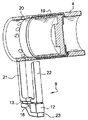
図1は、全体に円筒形形状のマスターシリンダ1を示す。マスターシリンダ1の本体2にはボア3が形成されている。ピストン4がボア3内で並進移動する。
[Example]
FIG. 1 shows a master cylinder 1 having a generally cylindrical shape. A bore 3 is formed in the main body 2 of the master cylinder 1. The piston 4 translates in the bore 3.
タンデムマスターシリンダの場合、ピストン4によって表されるのは、好ましくは副ピストンである。確かに、タンデムマスターシリンダでは、副ピストンの移動がブレーキペダルの移動を最も良く表す。ピストンの移動により、圧力チャンバ5の容積を変化させる。
In the case of a tandem master cylinder, what is represented by the piston 4 is preferably an auxiliary piston. Indeed, in a tandem master cylinder, the movement of the secondary piston best represents the movement of the brake pedal. The displacement of the piston changes the volume of the
マスターシリンダ1には液圧流体リザーバ(図示せず)が固定されている。液圧流体は、例えば、ブレーキパッドに分配される。液圧リザーバに設けられたチューブ状のノズル(管状のノズル)が、例えば、リザーバのチューブ状ノズルと対応する寸法のボア6に押し込まれる。供給オリフィス7により、液圧流体を、液圧流体リザーバからマスターシリンダのチャンバ5に通過させることができる。ボア6は、マスターシリンダ3の上部分に配置されるものと考えられる。
A hydraulic fluid reservoir (not shown) is fixed to the master cylinder 1. Hydraulic fluid is distributed, for example, to brake pads. A tubular nozzle (tubular nozzle) provided in the hydraulic reservoir is, for example, pushed into a bore 6 of a size corresponding to the tubular nozzle of the reservoir. The supply orifice 7 allows hydraulic fluid to pass from the hydraulic fluid reservoir to the
ボア6の反対側の、マスターシリンダ1の下領域8は、制動システムの作動を検出するためのシステム9を備えている。検出システム9は、磁気感知システムである。検出システム9は、磁気回路を有する。例えば、検出システム9は、二つの磁極片10及び11を備えている。磁石12が、二つの枝部10と11との間に配置されている。磁石12は、分極された又は磁化された(polarized)永久磁石であってもよい。磁気検出器13即ちセンサが、更に、二つの磁極片10及び11間に配置されている。空隙16が、磁石12の位置に及びセンサ13の位置に形成されている。別の空隙が、移動磁極片19の位置に形成されている。
The lower area 8 of the master cylinder 1, opposite the bore 6, is provided with a system 9 for detecting the activation of the braking system. The detection system 9 is a magnetic sensing system. The detection system 9 has a magnetic circuit. For example, the detection system 9 comprises two
図1では、磁気検出器13が、磁気回路の一方の側を閉じる、即ち磁極片11の下端14と磁極片10の下端15との間に配置されている。磁石12は、磁気検出器13とピストン4との間に配置される。
In FIG. 1, a
磁石12及び磁気検出器13の位置を逆にすることもできる。
二つの磁極片10及び11でなく、三つの磁極片を設けることができるということは明らかである。例えば、二つの磁極片間に空間が形成され、磁石がこの空間内に配置される。第3磁極片が回路を閉じる。磁気検出器は、この場合、最初の二つの磁極片のうちの一方及び第3磁極片が形成する第2空間に収容されていてもよい。
The positions of the
Obviously, instead of two
図1では、磁極片10及び11の上端17及び18はピストン4のボア3で終端する。移動磁極片19が、ピストン4に固定されているか或いはこのピストン上に成形されている。この移動磁極片19が、磁気回路9を開閉する。移動磁極片19もまた磁極片である。
In FIG. 1, the upper ends 17 and 18 of the
これらの磁極片は、例えば鋼製である。マスターシリンダは、アルミニウム又は任意の他の非磁性体で形成することができる。
ピストン4に取り付けられた磁極片19は、マスターシリンダ1のボア3内で並進移動する。磁極片19は、ピストン4及び従って移動磁極片19の移動により、磁気回路を開閉するように位置決めされている。
These pole pieces are for example made of steel. The master cylinder can be made of aluminum or any other non-magnetic material.
The
図1では、移動磁極片19はピストン4の輪郭に従う。しかしながら、移動磁極片19は、ピストン4の全輪郭をに従わなくてもよい。実際には、移動磁極片19は、磁極片10及び11の端部17及び18のところで磁気回路9を閉鎖するのに十分な寸法を備えていさえすればよい。従って、ピストン4を形成する円筒体の下部分に配置された例えば半円筒形形状の移動磁極片19を提供することができる。
In FIG. 1, the moving
ブレーキペダルによって間接的に作動されるピストン4は、ボア3内で並進移動する。ピストン4の移動により、移動磁極片19を移動させる。この移動により、磁界の大きさを変化させる。センサ13はこの変動を計測する。センサ13は、空隙16内の磁界の大きさに従って制動灯の点灯又は消灯を切り換える電気システム(図示せず)に接続される。
The piston 4, which is indirectly activated by the brake pedal, translates in the bore 3. The movement of the piston 4 causes the moving
本発明によるマスターシリンダは、エンジンルーム内での占有容積が従来技術のマスターシリンダよりも小さいということは容易に理解されよう。確かに、検出装置がマスターシリンダの一端に固定されていないため、その長さは、制動システムの作動を検出する装置が装着されていないマスターシリンダと比べても大きくならない。 It will be readily appreciated that the master cylinder according to the invention occupies less space in the engine compartment than the prior art master cylinder. Indeed, since the detection device is not fixed to one end of the master cylinder, its length is not greater than that of a master cylinder without a device for detecting the operation of the braking system.
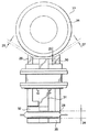
図2及び図3は、本発明のマスターシリンダに組み込んだ磁気回路の長さ方向断面図である。マスターシリンダ(図2及び図3には図示せず)は、複数の膨張穴(又は拡張穴)を持つマスターシリンダである。マスターシリンダは、更に、弁を持つマスターシリンダ、又は任意の他の周知のマスターシリンダであってもよい。 2 and 3 are longitudinal sectional views of a magnetic circuit incorporated in the master cylinder of the present invention. The master cylinder (not shown in FIGS. 2 and 3) is a master cylinder having a plurality of expansion holes (or expansion holes). The master cylinder may also be a master cylinder with a valve or any other known master cylinder.
ピストン4には膨張穴20(又は拡張穴)が設けられている。
図2及び図3では、磁気回路9は、固定された三つの磁極片21、22、及び23で形成されている。これらの磁極片21、22、及び23は、例えば、U形状を形成する。磁極片21及び22は、U形状の二つの枝部を形成し、ピストン4に対して垂直である。磁極片23は、ピストン4と平行なU形状のベースを形成する。磁石12は、例えば、磁極片22の下端と磁極片23との間に形成された空間内に収容されている。磁気検出器13は、例えば、磁極片21の下端と磁極片23との間に形成された空間内に収容されている。磁極片21及び22の下端は、ピストン4から最も遠い端部を意味すると理解されるべきである。
The piston 4 is provided with an expansion hole 20 (or an expansion hole).
2 and 3, the magnetic circuit 9 is formed of three fixed
図2では、移動磁極片19は、スリーブチューブ(すなわち、チューブ状のスリーブ又は管状のスリーブ)に形成されている。スリーブチューブ19は、例えば、プッシュロッドと同じ側で、即ちマスターシリンダの閉鎖端とは反対側で、膨張穴20の近くでピストン4内に成形されている。スリーブチューブ19は、更に、ピストンに取り付けられていてもよい。かくして、マスターシリンダが休止位置にあるとき、即ちブレーキペダルが作動されていないとき、磁気回路9は開いている。換言すると、スリーブチューブ19は磁気回路から離間されている。
In FIG. 2, the moving
図2に示す形態では、磁気回路9が開いている場合には、制動灯は消灯している。制動状態では、運転者がブレーキペダルを踏み込むことによりマスターシリンダを作動する。ピストン4はボアの内側で移動する。移動磁極片19が磁気回路9に近接し、回路を閉鎖する。センサ13が測定する又は計測する磁界の大きさが変化する。センサ13は、従って、情報を電気システムに送出し、制動灯を点灯する。
In the embodiment shown in FIG. 2, when the magnetic circuit 9 is open, the brake lights are off. In the braking state, the driver operates the master cylinder by depressing the brake pedal. The piston 4 moves inside the bore. The moving
制動の持続時間に亘って制動灯を点灯状態に維持する必要がある。従って、移動磁極片19は、制動中に亘って、即ちボアに沿ったピストン4の前進中に亘って、磁気回路を閉じた状態に保持するのに十分な長さを備えていなければならない。従って、制動灯は、制動の中間で不時に消灯されることがない。また、制動灯は、マスターシリンダの休止位置への戻り中に亘り、即ち、車輛の減速中に亘って、停止するまで、又は再度加速するまで、点灯状態のままでなければならない。従って、移動磁極片19の長さは、ピストン4の作動ストローク(換言すれば、働き行程、動作行程、又は動力行程)とほぼ等しくなければならない。
It is necessary to keep the brake lights on for the duration of braking. Accordingly, the moving
ブレーキペダルを放すと、ピストン4は、移動磁極片19とともに休止位置に戻る。次いで、磁気回路9が再度開く。センサ13によって計測した磁界の大きさが変化する。センサ13は、電気システムに指令を送り、制動灯を消灯する。
When the brake pedal is released, the piston 4 returns to the rest position with the moving
磁気回路は定置である。制動時に磁極片19が移動して磁気回路9を閉じることができる。次いで、制動灯が点灯される。
移動磁極片19は、マスターシリンダチャンバ内の圧力が上昇する前でも移動する。センサ13によって検出される磁界の変化は、制動前でも起こる。従って、制動の早期検出がなされ、制動灯は制動と同期して点灯される。
The magnetic circuit is stationary. During braking, the
The moving
図3は、本発明の別の実施例を示す。移動磁極片19は、ピストン4内に成形されている。
移動磁極片19は、図3では、リング19で形成されている。このリング19は、例えば、膨張穴20の近くに配置される。磁気回路9は、リング19に面して位置決めされる。即ち、マスターシリンダが休止状態にあるときにリング19が磁気回路9を閉じる。磁界の大きさは、センサ13によって測定又は計測される。センサ13は、制動灯の消灯又は点灯を指令する電気システム(図示せず)に情報を送る。
FIG. 3 shows another embodiment of the present invention. The moving
The moving
制動時には、ブレーキペダルが踏み込まれ、これによりピストン4をボア内で前進させる。ピストン4の並進移動により、リング19を並進移動させる。リング19は、従って、磁気回路9から遠ざかるように移動する。従って、磁気回路9が開く。センサ13によって測定され又は計測された磁界の大きさが変化する。電気システム(図示せず)に送出された情報により点灯が行われる。
During braking, the brake pedal is depressed, causing the piston 4 to move forward in the bore. The translation of the piston 4 causes the
ピストン4のストロークの持続時間に亘って、磁気回路9は開いている。磁気回路が開くのに伴って制動灯が点灯される。
ブレーキペダルを放すと、ピストン4はその元の位置に戻る。従って、リング19がその元の位置に戻り、磁気回路9を閉じる。センサ13によって測定され又は計測された磁界の大きさが再び変化する。情報が電気回路に送出され、制動灯が消灯される。
For the duration of the stroke of the piston 4, the magnetic circuit 9 is open. The brake light is turned on as the magnetic circuit opens.
When the brake pedal is released, the piston 4 returns to its original position. Accordingly, the
かくして、図3に示す例示の実施例では、磁気回路が閉じたとき、制動灯が消灯する。ピストン4がマスターシリンダ内で並進移動したとき、即ちブレーキペダルを作動したとき、リング19もまた移動する。センサ13によって測定され又は計測された磁界の大きさが変化する。従って、制動灯を点灯する情報が電気回路に送出される。ピストン4の移動中に亘り、磁気回路が開き、制動灯が点灯する。
Thus, in the exemplary embodiment shown in FIG. 3, when the magnetic circuit is closed, the brake light is turned off. When the piston 4 translates in the master cylinder, ie when the brake pedal is actuated, the
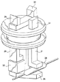
図4のa及びbは、本発明の特定の実施例を示す。センサにはリードスイッチが設けられている。このリードスイッチ回路は、例えば、バルブ(bulb)28内に収容されている。 4a and 4b show a specific embodiment of the present invention. The sensor is provided with a reed switch. This reed switch circuit is housed in, for example, a valve (bulb) 28.
磁気回路は三つの磁極片29、30、及び31を備えており、これらの磁極片は固定されている。図示の例では、これらの磁極片29、30、及び31は互いに平行であり且つマスターシリンダ本体33に対して垂直である。三つの磁極片のうちの一つである磁極片30は、マスターシリンダとは反対側の端部がベース35で終端する。
The magnetic circuit comprises three
一つの移動磁極片(図示せず)がピストン34に、あるいはピストン34の内側に収容されている。有利には、休止状態で、移動磁極片は、磁極片29及び30に面している。しかしながら、ピストン34が作動されていない場合に、移動磁極片を磁極片29、30、及び31から離しておくための手段が設けるようにすることもできる。
One moving pole piece (not shown) is housed in or inside the
リードスイッチ検出器が磁束に対して非常に敏感であるため、マスターシリンダのピストン34が休止位置にあるときに検出作業が最も確実に行われるように、バルブ28を含む回路内に磁界がないか或いはできるだけ弱くするのが好ましい。このため、二つの磁気回路を使用する。二つの磁極片29及び30によって形成された第1磁気回路は磁石32を収容している。例えば、その磁石32は、磁極片29の下端と磁極片30のベース35との間に配置される。ピストン34が作動されていない場合には、残留磁束は、この回路を通って流れる。磁極片29及び磁極片31によって形成された第2回路には、リードスイッチバルブ28が収容されている。ピストン34が作動されていない場合には、この第2回路を通って流れる磁束はない。
Since the reed switch detector is very sensitive to magnetic flux, there should be no magnetic fields in the circuit containing the
ピストン34が前進すると、移動磁極片が前進して磁極片29及び30に近づき、次いで磁極片31に近づく。かくして磁束は第1の回路を通って流れた後、第2の回路を通って流れる。
As the
図4のaに示す例示の実施例では、一方では、第1空隙26が、磁極片29とピストン34の移動磁極片との間に形成され、第2空隙27が、磁極片30と移動磁極片との間に形成される。これらの二つの空隙26及び27により、ピストン34が作動されていない場合でも残留磁束を流すことができる。
In the exemplary embodiment shown in FIG. 4a, on the one hand, a
他方、第3空隙25が、磁極片31とピストン34の移動磁極片との間に形成され、第4空隙24が、磁極片29と磁極片31との間に形成され、有利には、ピストン34が作動されていない場合にリードスイッチバルブを作動しないように十分弱い磁束だけを通すことができる。
On the other hand, a
これを達成するため、第1及び第2の空隙26及び27の和が、第1、第2、及び第3の空隙26、25、24の和よりも小さいのが有利である。更に有利には、第1及び第2の空隙26及び27の和が、第1、第2、及び第3の空隙26、25、24の和よりも厳密に大きいのが有利である。かくして、磁極片29及び31によって形成された回路に含まれるリードスイッチバルブ28は、ピストン34が作動されていない場合には、残留磁束から完全に遮断される。磁石32を含む磁気回路自体により残留磁束を循環させることができる。ピストン34が前進すると直ぐに、バルブ28を含む磁気回路が閉じ、磁束をその中で循環させることができる。
To achieve this, the sum of the first and
センサ即ち磁気検出器は、ホール効果セル又は磁気抵抗効果(AMR、GMR)セルを含んでもよい。
移動磁極片は、ピストン上に成形され、被せられ、又は固定される。しかしながら、本発明の好ましい例示の実施例では、移動磁極片は、ピストン内に成形され又は固定される。移動磁極片は、例えば、プラスチック製ピストンに被せられていてもよい。
The sensor or magnetic detector may include a Hall effect cell or a magnetoresistive effect (AMR, GMR) cell.
The moving pole piece is molded, covered or fixed on the piston. However, in a preferred exemplary embodiment of the present invention, the moving pole piece is molded or fixed in the piston. The moving pole piece may for example be covered by a plastic piston.
更に、移動磁極片をピストンの内側に取り付けることもできる。この場合、例えば、移動磁極片として割れ目を持つリング又はスリーブチューブを使用できる。磁極片をその直径の間隔が詰まるように閉じることによって、割れ目を備えた移動磁極片をピストンの内側に挿入する。ピストンの内側に挿入されると、割れ目を備えた磁極片はピストンの内輪郭に嵌着するまで解放し、弛緩する。 Further, the moving pole piece can be mounted inside the piston. In this case, for example, a ring or a sleeve tube having a split can be used as the moving pole piece. The moving pole piece with the split is inserted inside the piston by closing the pole piece to close its diameter. When inserted inside the piston, the split pole piece releases and relaxes until it snaps into the inner contour of the piston.
かくして、特に膨張穴を持つマスターシリンダの場合には、ピストンの外輪郭は完全に滑らかである。ピストンは、マスターシリンダの本体内で摺動するとき、少なくとも一つのシーリングカップと接触する。シーリングカップは、マスターシリンダに形成されたボア内に収容されている。ボアは、内部でピストンが摺動する圧力チャンバのところで部分的に開放している。移動磁極片がピストンの内側にあり且つピストンの外輪郭が完全に滑らかな本発明のこのような実施例により、ピストンの前進時にシーリングカップが損傷しないようにできる。 Thus, especially in the case of a master cylinder with an expansion hole, the outer contour of the piston is completely smooth. The piston contacts at least one sealing cup as it slides within the body of the master cylinder. The sealing cup is housed in a bore formed in the master cylinder. The bore is partially open at the pressure chamber in which the piston slides. Such an embodiment of the invention in which the moving pole piece is inside the piston and the outer contour of the piston is perfectly smooth can prevent the sealing cup from being damaged when the piston is advanced.
移動磁極片をマスターシリンダの本体の内側で並進移動させることができる任意の他の固定手段が、本発明の範疇に含まれる。
分極磁石は、温度に関して磁気損失(magnetic loss)が小さい材料から、AlNiCo又はサマリウムコバルトのタイプの材料から形成されていてもよい。
Any other securing means by which the moving pole piece can be translated inside the body of the master cylinder are within the scope of the present invention.
The polarizing magnet may be formed from a material with a low magnetic loss with respect to temperature, from a material of the type AlNiCo or samarium cobalt.
一般的にはマスターシリンダは、アルミニウム等の任意の非磁性体から形成することができる。
磁気回路を形成する磁極片及び移動エレメントは、例えば強磁性体から形成される。必要な精度に応じて、磁極片は、例えば、従来のXC10型鋼、又はサンドヴィック社(R Fe 80C参照)が販売しているX6CrNiMoTi17−12−2又はX5CrNiMo17−12−2等の優れた強磁性を持つ鋼でできている。
Generally, the master cylinder can be formed from any non-magnetic material such as aluminum.
The pole pieces and the moving elements forming the magnetic circuit are formed, for example, of ferromagnetic material. Depending on the required accuracy, the pole pieces can be made of an excellent ferromagnetic material such as, for example, conventional XC10 steel or X6CrNiMoTi17-12-2 or X5CrNiMo17-12-2 sold by Sandvik (see R Fe 80C). Made of steel with
このようなセンサは、一つの部片の他の部片に対する位置を知ることを必要とする全ての機能について使用できる。 Such a sensor can be used for all functions that require knowing the position of one piece with respect to another.
1 マスターシリンダ
2 マスターシリンダ本体
4 ピストン
5 圧力チャンバ
9 磁気回路
19 移動磁極片
DESCRIPTION OF SYMBOLS 1 Master cylinder 2 Master cylinder body 4
Claims (13)
非磁性体製のマスターシリンダ(1)の本体(2)と、
前記マスターシリンダの前記本体に形成されたボア(3)と、
前記ボアの内側の可変容積圧力チャンバ(5)と、
前記ボア内で摺動する、前記圧力チャンバの容積を変化するピストン(4)と、
前記マスターシリンダの前記本体に固定された、前記ピストンの通路に向いた、前記制動システムの作動を検出する検出装置(9)であって、磁極片(19)によって開閉できる少なくとも一つの磁気回路(9)を備えた検出装置とを備えた、マスターシリンダにおいて、
前記磁気回路は、少なくとも二つの磁極片(10、11)と、磁石(12)と、磁気感知エレメント(13)とを備える、ことを特徴とするマスターシリンダ。 A master cylinder for a vehicle braking system,
A main body (2) of a non-magnetic master cylinder (1);
A bore (3) formed in the main body of the master cylinder;
A variable volume pressure chamber (5) inside said bore;
A piston (4) that slides in the bore and changes the volume of the pressure chamber;
A detection device (9) fixed to the main body of the master cylinder, facing the passage of the piston, for detecting the operation of the braking system, wherein at least one magnetic circuit (9) can be opened and closed by a pole piece (19); 9) A master cylinder comprising a detection device comprising:
A master cylinder, characterized in that the magnetic circuit comprises at least two pole pieces (10, 11), a magnet (12) and a magnetic sensing element (13).
前記磁極片はリング(19)であり、前記マスターシリンダが前記休止位置にあるとき、前記磁気回路は閉じている、ことを特徴とするマスターシリンダ。 The master cylinder according to claim 1,
A master cylinder, wherein the pole piece is a ring (19) and the magnetic circuit is closed when the master cylinder is in the rest position.
前記磁極片は、前記ピストンの作動ストロークとほぼ等しい長さのスリーブチューブ(19)であり、前記マスターシリンダが休止位置にある場合、前記磁気回路は開いている、ことを特徴とするマスターシリンダ。 The master cylinder according to claim 1,
A master cylinder, characterized in that said pole piece is a sleeve tube (19) of a length approximately equal to the working stroke of said piston, and said magnetic circuit is open when said master cylinder is in a rest position.
前記磁気回路には、二つの磁極片(10、11)が設けられており、
前記二つの磁極片(10、11)は、一方では前記磁石の位置及び前記磁気感知エレメントの位置に空隙を形成しており、他方では移動磁極片の位置に空隙を形成している、ことを特徴とするマスターシリンダ。 In the master cylinder according to any one of claims 1 to 3,
The magnetic circuit is provided with two pole pieces (10, 11),
The two pole pieces (10, 11) on the one hand form a gap at the position of the magnet and at the position of the magnetic sensing element, and on the other hand form a gap at the position of the moving pole piece. Features a master cylinder.
前記磁気回路は、ほぼU形状を形成する三つの磁極片(21、22、23)を有しており、
二つの磁極片(21及び22)が前記U形状の二つの枝部を形成し、
一つの磁極片(23)が前記U形状のベースを形成し、
前記磁石の位置に空隙が形成され、
別の空隙が前記磁気感知エレメントの位置に形成され、
第3空隙が前記移動磁極片の位置に形成されている、ことを特徴とするマスターシリンダ。 The master cylinder according to any one of claims 1 to 4,
The magnetic circuit has three pole pieces (21, 22, 23) forming a substantially U shape,
Two pole pieces (21 and 22) forming two branches of the U-shape;
One pole piece (23) forms the U-shaped base;
A void is formed at the position of the magnet,
Another gap is formed at the location of the magnetic sensing element,
A master cylinder, wherein a third gap is formed at a position of the moving pole piece.
前記磁気感知エレメントは、ホールセル又は磁気抵抗型の、磁界変化を感知するセンサである、ことを特徴とするマスターシリンダ。 The master cylinder according to any one of claims 1 to 5,
The master cylinder according to claim 1, wherein the magnetic sensing element is a Hall cell or a magnetoresistive sensor for sensing a magnetic field change.
前記磁気感知エレメントは、リードスイッチ型の、磁界変化を感知するセンサである、ことを特徴とするマスターシリンダ。 The master cylinder according to any one of claims 1 to 5,
The master cylinder according to claim 1, wherein the magnetic sensing element is a reed switch type sensor for sensing a magnetic field change.
前記検出装置は、第1磁気回路と第2磁気回路とを備え、前記第1磁気回路には磁石が設けられ、前記第2磁気回路には、前記リードスイッチ型の回路が設けられ、その結果、前記ピストンが休止位置にある場合には、前記第2磁気回路を通って流れることができる磁束は、前記リードスイッチ回路を作動するには不十分である、ことを特徴とするマスターシリンダ。 The master cylinder according to claim 7,
The detection device includes a first magnetic circuit and a second magnetic circuit, wherein the first magnetic circuit is provided with a magnet, and the second magnetic circuit is provided with the reed switch type circuit. Master cylinder, wherein when the piston is in the rest position, the magnetic flux that can flow through the second magnetic circuit is insufficient to operate the reed switch circuit.
前記第1磁気回路は、二つの磁極片(29及び30)によって形成され、
磁石(32)が、前記第1磁気回路に収容されており、
前記第2磁気回路は、第1磁極片(29)及び第3磁極片(31)によって形成されている、ことを特徴とするマスターシリンダ。 The master cylinder according to claim 8,
The first magnetic circuit is formed by two pole pieces (29 and 30);
A magnet (32) is housed in the first magnetic circuit;
A master cylinder, wherein the second magnetic circuit is formed by a first pole piece (29) and a third pole piece (31).
空隙(26)が、前記磁極片(29)と、前記マスターシリンダのピストン(34)によって支持された移動磁極片との間に形成され、
第2空隙(27)が、前記磁極片(30)と前記移動磁極片との間に形成され、
第4空隙(24)が、前記磁極片(29)と前記磁極片(31)との間に形成され、
第3空隙(25)が、前記磁極片(31)と前記移動磁極片との間に形成される、ことを特徴とするマスターシリンダ。 The master cylinder according to claim 9,
An air gap (26) is formed between the pole piece (29) and a moving pole piece supported by the master cylinder piston (34);
A second gap (27) is formed between the pole piece (30) and the moving pole piece;
A fourth gap (24) is formed between the pole piece (29) and the pole piece (31);
A master cylinder, wherein a third gap (25) is formed between the pole piece (31) and the moving pole piece.
第1及び第2の空隙(26及び27)の和が、第1、第2、及び第3の空隙(24、25、26)の和よりも小さい、ことを特徴とするマスターシリンダ。 The master cylinder according to claim 10,
A master cylinder, wherein the sum of the first and second gaps (26 and 27) is smaller than the sum of the first, second, and third gaps (24, 25, 26).
前記磁極片(29、30、31)は、互いに平行であり、前記ピストン(34)の前方移動に対して垂直である、ことを特徴とするマスターシリンダ。 The master cylinder according to any one of claims 7 to 11,
A master cylinder, wherein the pole pieces (29, 30, 31) are parallel to each other and perpendicular to forward movement of the piston (34).
前記磁極片及び前記移動エレメントは、強磁性体で形成されている、ことを特徴とするマスターシリンダ。 The master cylinder according to any one of claims 1 to 12,
A master cylinder, wherein the pole piece and the moving element are formed of a ferromagnetic material.
Applications Claiming Priority (1)
| Application Number | Priority Date | Filing Date | Title |
|---|---|---|---|
| FR0302203A FR2851538B1 (en) | 2003-02-21 | 2003-02-21 | MASTER CYLINDER OF A MOTOR VEHICLE WITH A DETECTION DEVICE FOR ACTUATING A BRAKING SYSTEM |
Publications (1)
| Publication Number | Publication Date |
|---|---|
| JP2004249985A true JP2004249985A (en) | 2004-09-09 |
Family
ID=32732051
Family Applications (1)
| Application Number | Title | Priority Date | Filing Date |
|---|---|---|---|
| JP2004043940A Pending JP2004249985A (en) | 2003-02-21 | 2004-02-20 | Master cylinder for automobile having device for detecting actuation of braking system |
Country Status (7)
| Country | Link |
|---|---|
| US (1) | US7018002B2 (en) |
| EP (1) | EP1449729B1 (en) |
| JP (1) | JP2004249985A (en) |
| AT (1) | ATE391643T1 (en) |
| DE (1) | DE602004012911T2 (en) |
| ES (1) | ES2302989T3 (en) |
| FR (1) | FR2851538B1 (en) |
Cited By (3)
| Publication number | Priority date | Publication date | Assignee | Title |
|---|---|---|---|---|
| JP2008230602A (en) * | 2007-03-22 | 2008-10-02 | Robert Bosch Gmbh | Method and booster for detecting braking of vehicle, and manufacturing method of the booster |
| JP2009274523A (en) * | 2008-05-13 | 2009-11-26 | Nissin Kogyo Co Ltd | Apparatus for detecting piston position in master cylinder |
| KR101913610B1 (en) * | 2011-12-13 | 2018-10-31 | 현대모비스 주식회사 | Brake light signal sensor |
Families Citing this family (9)
| Publication number | Priority date | Publication date | Assignee | Title |
|---|---|---|---|---|
| DE10352589B4 (en) * | 2003-11-11 | 2005-09-08 | Lucas Automotive Gmbh | Main brake cylinder for a motor vehicle hydraulic brake system has attached measuring unit and movable piece to give electric signal on cylinder operation |
| FR2885108B1 (en) * | 2005-04-28 | 2008-12-05 | Bosch Gmbh Robert | MASTER CYLINDER DEVICE FOR MOTOR VEHICLE |
| KR101122310B1 (en) * | 2007-02-26 | 2012-03-21 | 가부시키가이샤후지쿠라 | Magnetic sensor module and piston position detecting device |
| FR2921481B1 (en) * | 2007-09-24 | 2009-11-27 | Skf Ab | ROTATION DETECTION DEVICE AND INSTRUMENTAL BEARING EQUIPPED WITH SUCH A DEVICE |
| WO2012003273A2 (en) | 2010-06-30 | 2012-01-05 | Kelsey-Hayes Company | Position sensing assembly for use with a vehicle hydraulic master cylinder of a vehicle braking system and master cylinder assembly including such a position sensing assembly |
| KR101888453B1 (en) * | 2011-10-13 | 2018-08-14 | 현대모비스 주식회사 | Brake device |
| CN104245448B (en) * | 2012-02-14 | 2017-03-08 | 大陆-特韦斯贸易合伙股份公司及两合公司 | There is the position of the piston that can move along a straight line for non-contact type monitoring and the master cylinder of the device of motion |
| DE102014223731A1 (en) * | 2014-11-20 | 2016-05-25 | Robert Bosch Gmbh | Sensor device, hydraulic unit for interaction with the sensor device, brake system and method for mounting the sensor device |
| EP3620754B1 (en) | 2018-09-06 | 2022-01-05 | KNORR-BREMSE Systeme für Nutzfahrzeuge GmbH | A magnet holder and stroke sensor with the magnet holder |
Citations (5)
| Publication number | Priority date | Publication date | Assignee | Title |
|---|---|---|---|---|
| JPS5926355A (en) * | 1982-08-05 | 1984-02-10 | Yamaha Motor Co Ltd | Brake switch for hydraulic type brake |
| JPS59120802A (en) * | 1982-12-27 | 1984-07-12 | Toshiba Mach Co Ltd | Apparatus for detecting displacement |
| JPS63503159A (en) * | 1986-04-29 | 1988-11-17 | ヒビルステツド,ニエル | Hydraulic cylinder with a piston and a magnetic device for determining the position of the piston |
| JPH11211410A (en) * | 1998-01-30 | 1999-08-06 | Matsushita Electric Ind Co Ltd | Non-contact position sensor |
| JP2001174207A (en) * | 1999-12-15 | 2001-06-29 | Mitsubishi Heavy Ind Ltd | Displacement gauge and measuring method for displacement amount |
Family Cites Families (29)
| Publication number | Priority date | Publication date | Assignee | Title |
|---|---|---|---|---|
| US2987669A (en) * | 1959-01-19 | 1961-06-06 | Gulton Ind Inc | Hall effect electromechanical sensing device |
| DE1161698B (en) * | 1959-05-20 | 1964-01-23 | Bayer Ag | Measuring device with a Hall probe that can move freely between the poles of a magnet |
| US3752039A (en) * | 1971-12-22 | 1973-08-14 | Ibm | Master-slave hydraulic control system |
| FR2331774A1 (en) * | 1975-11-12 | 1977-06-10 | Radiotechnique Compelec | METHOD OF DYNAMIC LOCATION OF PARTICULAR POSITIONS OF MOVABLE PARTS USING A HALL-EFFECT CRYSTAL AND DEVICES FOR IMPLEMENTING THE PROCESS |
| FR2388248A1 (en) * | 1977-04-20 | 1978-11-17 | Radiotechnique Compelec | HALL-EFFECT POSITION DETECTOR |
| DE2945895C2 (en) * | 1979-11-14 | 1986-06-05 | Festo-Maschinenfabrik Gottlieb Stoll, 7300 Esslingen | Magnetic position transmitter for hydraulic or pneumatic working cylinders |
| DE3380447D1 (en) * | 1982-07-02 | 1989-09-28 | Deutsche Forsch Luft Raumfahrt | Transducer |
| US4639665A (en) * | 1983-08-22 | 1987-01-27 | Borg-Warner Corporation | Sensing system for measuring a parameter |
| DE3410736A1 (en) * | 1984-03-23 | 1985-10-03 | Wabco Westinghouse Fahrzeug | ANALOGUE SENSOR |
| US4855675A (en) * | 1984-05-21 | 1989-08-08 | Sacol Powerline Limited | Inductive transducers for indicating establishment of a preselected spatial relationship between two parts |
| DE3713880A1 (en) * | 1987-04-25 | 1988-11-17 | Vdo Schindling | MAGNETIC BARRIERS |
| US4857824A (en) * | 1987-07-16 | 1989-08-15 | Cadillac Gage Textron Inc. | Movable core position transducer |
| US4914916A (en) * | 1988-04-04 | 1990-04-10 | Automotive Products Plc | Tandem master cylinder with electromagnetic position sensors for each piston |
| US5477675A (en) * | 1989-02-17 | 1995-12-26 | Nartron Corporation | Fluid power assist method and apparatus |
| DE9010114U1 (en) * | 1990-07-03 | 1990-09-06 | Festo Kg, 7300 Esslingen, De | |
| FR2691534B1 (en) * | 1992-05-19 | 1994-08-26 | Moving Magnet Tech | Permanent magnet position sensor and hall sensor. |
| DE4341810B4 (en) * | 1993-12-08 | 2004-01-29 | Festo Ag & Co | Sensor device for position detection of a piston |
| US5600238A (en) * | 1994-07-05 | 1997-02-04 | Ford Motor Company | Method and apparatus for detecting the linear or rotary position of an object through the use of a variable magnetic shunt disposed in parallel with a yoke air gap |
| JPH08226826A (en) * | 1995-02-22 | 1996-09-03 | Mikuni Corp | Magnetic position sensor |
| US6346806B1 (en) * | 1997-03-12 | 2002-02-12 | Pepperl +Fuchs Gmbh | Device for detecting the position of a moveable magnet to produce a magnetic field |
| US6304078B1 (en) * | 1998-12-09 | 2001-10-16 | Cts Corporation | Linear position sensor |
| DE10053995A1 (en) * | 2000-10-31 | 2002-05-08 | Continental Teves Ag & Co Ohg | Signal generator with Hall sensor integrated in a master cylinder |
| DE10133163A1 (en) * | 2001-02-20 | 2002-08-29 | Bosch Gmbh Robert | measuring system |
| US6619039B2 (en) * | 2001-04-25 | 2003-09-16 | Delphi Technologies, Inc. | Brake master cylinder-sensor system and method |
| FR2825331B1 (en) * | 2001-05-30 | 2003-09-19 | Bosch Gmbh Robert | IMPROVED DEVICE FOR DETECTING THE OPERATION OF A BRAKING SYSTEM, AND APPLICATION |
| US6652039B1 (en) * | 2002-09-30 | 2003-11-25 | Robert Bosch Corporation | Anti-lock braking system with accumulator volume monitoring |
| FR2848936B1 (en) * | 2002-12-20 | 2006-02-10 | Bosch Gmbh Robert | MASTER CYLINDER COMPRISING AN ACTUATION DETECTING DEVICE OF A BRAKING SYSTEM AND VEHICLE COMPRISING SUCH A MASTER CYLINDER |
| US7221151B2 (en) * | 2003-01-31 | 2007-05-22 | Delphi Technologies, Inc. | Magnetic array position sensor |
| EP1489385B1 (en) * | 2003-06-11 | 2016-07-20 | FTE automotive GmbH | Device for detecting the axial position of a first part which is moveable relative to a second part |
-
2003
- 2003-02-21 FR FR0302203A patent/FR2851538B1/en not_active Expired - Fee Related
-
2004
- 2004-02-16 AT AT04003360T patent/ATE391643T1/en not_active IP Right Cessation
- 2004-02-16 ES ES04003360T patent/ES2302989T3/en not_active Expired - Lifetime
- 2004-02-16 DE DE602004012911T patent/DE602004012911T2/en not_active Expired - Lifetime
- 2004-02-16 EP EP04003360A patent/EP1449729B1/en not_active Expired - Lifetime
- 2004-02-17 US US10/780,326 patent/US7018002B2/en not_active Expired - Fee Related
- 2004-02-20 JP JP2004043940A patent/JP2004249985A/en active Pending
Patent Citations (5)
| Publication number | Priority date | Publication date | Assignee | Title |
|---|---|---|---|---|
| JPS5926355A (en) * | 1982-08-05 | 1984-02-10 | Yamaha Motor Co Ltd | Brake switch for hydraulic type brake |
| JPS59120802A (en) * | 1982-12-27 | 1984-07-12 | Toshiba Mach Co Ltd | Apparatus for detecting displacement |
| JPS63503159A (en) * | 1986-04-29 | 1988-11-17 | ヒビルステツド,ニエル | Hydraulic cylinder with a piston and a magnetic device for determining the position of the piston |
| JPH11211410A (en) * | 1998-01-30 | 1999-08-06 | Matsushita Electric Ind Co Ltd | Non-contact position sensor |
| JP2001174207A (en) * | 1999-12-15 | 2001-06-29 | Mitsubishi Heavy Ind Ltd | Displacement gauge and measuring method for displacement amount |
Cited By (3)
| Publication number | Priority date | Publication date | Assignee | Title |
|---|---|---|---|---|
| JP2008230602A (en) * | 2007-03-22 | 2008-10-02 | Robert Bosch Gmbh | Method and booster for detecting braking of vehicle, and manufacturing method of the booster |
| JP2009274523A (en) * | 2008-05-13 | 2009-11-26 | Nissin Kogyo Co Ltd | Apparatus for detecting piston position in master cylinder |
| KR101913610B1 (en) * | 2011-12-13 | 2018-10-31 | 현대모비스 주식회사 | Brake light signal sensor |
Also Published As
| Publication number | Publication date |
|---|---|
| ES2302989T3 (en) | 2008-08-01 |
| US20040164611A1 (en) | 2004-08-26 |
| EP1449729A1 (en) | 2004-08-25 |
| FR2851538B1 (en) | 2006-04-28 |
| ATE391643T1 (en) | 2008-04-15 |
| FR2851538A1 (en) | 2004-08-27 |
| US7018002B2 (en) | 2006-03-28 |
| DE602004012911T2 (en) | 2009-06-04 |
| EP1449729B1 (en) | 2008-04-09 |
| DE602004012911D1 (en) | 2008-05-21 |
Similar Documents
| Publication | Publication Date | Title |
|---|---|---|
| JP2004249985A (en) | Master cylinder for automobile having device for detecting actuation of braking system | |
| BRPI0409218B1 (en) | device for monitoring the position and movement of a brake pedal. | |
| CN103129546B (en) | Electronic control brake booster | |
| ES2339409T3 (en) | BREAK SYSTEM. | |
| JP2019132754A (en) | Sensor unit | |
| US10173649B2 (en) | Brake master cylinder | |
| US4953444A (en) | Brake servo booster | |
| ATE422191T1 (en) | HANDLEBAR MOUNTED DUAL FUNCTION CONTROL DEVICE | |
| FR2885108A1 (en) | Master cylinder device for motor vehicle, has ferromagnetic ring placed at push rod displacing with primary piston inside master cylinder which has permanent magnet and magnetic field detector, where detector controls ignition of stoplight | |
| SE454968B (en) | AUTOMATIC BRAKE CONTROL SYSTEM AT START OF A VEHICLE EX IN A BACK | |
| JPH03148364A (en) | Master cylinder | |
| SE9903730D0 (en) | A lock actuator | |
| KR101076067B1 (en) | Stop lamp switch for vehicle | |
| US7014275B2 (en) | Automatic application hand brake applied sensor | |
| JPH0376761U (en) | ||
| KR101560622B1 (en) | Master cylinder | |
| JP2017531174A (en) | Automotive linear position sensor with Hall effect | |
| KR20140132477A (en) | Brake light switch | |
| KR960021746A (en) | Vehicle accelerator shift system | |
| JP4003153B2 (en) | Automatic brake device automatic operation detection device | |
| KR20150101601A (en) | Brake master cylinder | |
| KR20000026097A (en) | Brake booster of vehicle | |
| JPS6238845Y2 (en) | ||
| JP3445445B2 (en) | Shift lock mechanism of shift lever device | |
| FR2824038B1 (en) | DEVICE FOR DETECTING THE OPERATION OF A BRAKING SYSTEM, AND APPLICATION |
Legal Events
| Date | Code | Title | Description |
|---|---|---|---|
| A621 | Written request for application examination |
Free format text: JAPANESE INTERMEDIATE CODE: A621 Effective date: 20070117 |
|
| A977 | Report on retrieval |
Free format text: JAPANESE INTERMEDIATE CODE: A971007 Effective date: 20100118 |
|
| A131 | Notification of reasons for refusal |
Free format text: JAPANESE INTERMEDIATE CODE: A131 Effective date: 20100126 |
|
| A601 | Written request for extension of time |
Free format text: JAPANESE INTERMEDIATE CODE: A601 Effective date: 20100423 |
|
| A602 | Written permission of extension of time |
Free format text: JAPANESE INTERMEDIATE CODE: A602 Effective date: 20100428 |
|
| A521 | Request for written amendment filed |
Free format text: JAPANESE INTERMEDIATE CODE: A523 Effective date: 20100721 |
|
| A02 | Decision of refusal |
Free format text: JAPANESE INTERMEDIATE CODE: A02 Effective date: 20110209 |