JP2004238431A - Liquid crystal composition, retarder using the same, circular polarizer, and image display device - Google Patents
Liquid crystal composition, retarder using the same, circular polarizer, and image display device Download PDFInfo
- Publication number
- JP2004238431A JP2004238431A JP2003026849A JP2003026849A JP2004238431A JP 2004238431 A JP2004238431 A JP 2004238431A JP 2003026849 A JP2003026849 A JP 2003026849A JP 2003026849 A JP2003026849 A JP 2003026849A JP 2004238431 A JP2004238431 A JP 2004238431A
- Authority
- JP
- Japan
- Prior art keywords
- group
- liquid crystal
- ring
- layer
- optically anisotropic
- Prior art date
- Legal status (The legal status is an assumption and is not a legal conclusion. Google has not performed a legal analysis and makes no representation as to the accuracy of the status listed.)
- Granted
Links
- 0 CCC(CC1COc2cc3ccccc3cc2*Oc2cc(O*c3cc4ccccc4cc3OC*(C*3)=CN3S(C(*)=C)(=O)=O)cc(O*c3cc(cccc4)c4cc3OC)c2)NN1S(C(*N)=C)(=O)=O Chemical compound CCC(CC1COc2cc3ccccc3cc2*Oc2cc(O*c3cc4ccccc4cc3OC*(C*3)=CN3S(C(*)=C)(=O)=O)cc(O*c3cc(cccc4)c4cc3OC)c2)NN1S(C(*N)=C)(=O)=O 0.000 description 12
- ZKBUNGNDTCOGEU-UHFFFAOYSA-N Cc(cc(cc1)OC(c(cc2)ccc2OC(OCCCCOC(C=C)=O)=O)=O)c1OC(c(cc1)ccc1OC(OCCCCOC(C=C)=O)=O)=O Chemical compound Cc(cc(cc1)OC(c(cc2)ccc2OC(OCCCCOC(C=C)=O)=O)=O)c1OC(c(cc1)ccc1OC(OCCCCOC(C=C)=O)=O)=O ZKBUNGNDTCOGEU-UHFFFAOYSA-N 0.000 description 1
Abstract
Description
【0001】
【発明の属する技術分野】
本発明は、液晶性化合物を含む液晶組成物及び該液晶組成物を用いた光学異方性層を有する位相差板に関する。また該位相差板が2層以上の光学異方性層を有する場合、2つの光学異方性層の間に配向膜層を設けない位相差板に関する。さらにこれら位相差板を用いた画像表示装置に関するものである。
【0002】
【従来の技術】
光学異方性材料からなる位相差板は、LCD表示装置において必要な材料である。一種類の材料では、所望とする光学性能が達成できない場合は複数の光学材料を使用する場合がある。たとえば反射型液晶表示装置においてλ/4板が使用されているが、R,G,Bのいずれの波長域においても該λ/4板の位相差は波長の1/4であるような広帯域性を求められているが、かかる光学性能を1種の材料で満足することは難しく、λ/2板とλ/4板が使用されている。これらの材料はおのおのが数十μm以上の厚みを有しておりそれを粘着剤等で貼り合わせて使用している。これに対し、特開2001−4837号公報では長尺状の支持体に液晶性化合物からなる光学異方性層を2層積層して広帯域λ/4板を作製する技術が開示されている。また、液晶化合物を固定化して得られる層を多層積層する技術がUS6160597号明細書に開示されているが、液晶化合物を固定化して得られる層の間には配向膜層を別途形成しており、かかる積層方法では液晶化合物を塗布するためには必ずそのための配向膜を塗布する必要がある。つまり、液晶性化合物の配向を固定化して光学異方性層を1層形成するためには配向膜と液晶化合物を少なくとも2回塗布しなければならず、製造経費が高いものになってしまい、安価な製造技術が求められていた。さらに、塗布回数が増えれば増えるほど、塗布あるいは液晶化合物の配向の不具合によって製品故障が起きる確率が同じであっても出来上がった位相差板としては不具合の個所が多くなってしまい、目的の位相差板の得率が悪くなってしまう。そのため、製造時における得率を上げる意味からも塗布回数を減らすことが求められている。
【0003】
添加剤を空気界面側に移行させて表面層を形成する技術が提案されているが、該技術では、界面活性材料を添加して液晶組成物の空気界面側の傾斜配向を制御している(特許文献1参照)。しかしながら、特許文献1には、空気界面側の表面層にラビングを施して更に重合性液晶組成物からなる光学異方性層を形成する技術に関しては記載も示唆もされていない。また、重合性液晶組成物に表面を平滑にするために界面活性剤をレべリング剤として添加する技術が提案されている(特許文献2及び3参照)。特許文献2及び3には、レべリング剤の機能は液晶組成物の表面張力を低下させることにあり、表面張力を低下させることによって膜厚ムラに起因する光学的なムラを低減できると記載されている。しかしながら、これらにおいても、更に重合性液晶組成物からなる光学異方性層を形成する技術に関しては記載も示唆もされていない。
【0004】
我々は、特許文献3に記載のレベリング剤を用いて重合性液晶化合物からなる1層の光学異方性層を作製し、その表面にラビング処理を施し、更にもう1層の光学異方性層を形成することを試みた。しかしながら、1層目の表面がべたつき、レベリング剤がラビング布に転写したり、2層目の光学異方性層の配向性も不充分であることが明らかになった。
【0005】
【特許文献1】
特開2000−105315号公報
【特許文献2】
特開平11−148080号公報
【特許文献3】
特開平8−231958号公報
【0006】
【発明が解決しようとする課題】
本発明が解決しようとする課題は、液晶化合物の配向を固定化した層を有する位相差板において、固定化後の表面がべとつかず、表面を布などで擦っても添加剤などが転写しない位相差板、及び該位相差板の作製に有用な液晶組成物を提供することである。また、液晶化合物の配向を固定化した層を複数有する位相差板において、上層の液晶化合物を配向させるための配向膜を実質的に用いずに液晶化合物の配向を規制し固定化する方法で作製可能な位相差板、及び該位相差板の作製に有用な液晶組成物を提供することである。更には、該位相差板を用いた表示特性に優れた画像表示装置、及び画像表示装置の表示特性の向上に寄与する前記位相差板を用いた円偏光板を提供することである。
【0007】
【課題を解決するための手段】
上記課題は、以下の手段によって達成された。
(1) 液晶性化合物と、架橋性基を有する非液晶性ポリマーとを含有する液晶組成物。
(2) 架橋性基を有する非液晶性ポリマーが、一般式(III)で表される繰り返し単位を含むポリマーである(1)に記載の液晶組成物。
【0008】
一般式(III)
【化1】
(一般式(III)中、R31は水素原子又は炭素原子数1以上4以下のアルキル基を表す。P31はエチレン性不飽和基を含む一価の基であり、L31は単結合もしくは二価の連結基を表す。)
【0010】
(3) 一般式(III)中、R31が水素原子又はメチル基であり、P31がアクリロイル基、メタクリロイル基及びスチリル基から選ばれる基を含む一価の基であり、L31がアリーレン基、*―COO―、*―CONH―又は*―OCO―(*は主鎖に連結する位置を表す)である(2)に記載の液晶組成物。
(4) 3次元SP値を用いて算出されるδa値において、架橋性基を有する非液晶性ポリマーのδa値が、液晶性化合物のδa値よりも小さい(1)〜(3)のいずれかに記載の液晶組成物。
【0011】
(5) 透明支持体上に、(1)〜(4)のいずれかに記載の液晶組成物から形成される少なくとも1層の光学異方性層を有する位相差板。
(6) 透明支持体上に、少なくとも2層の光学異方性層を有し、少なくとも1層の光学異方性層が(1)〜(4)のいずれかに記載の液晶組成物から形成される光学異方性層を有する位相差板。
(7) 少なくとも2層の光学異方性層同士の間に、実質的に配向膜層を有さない(6)に記載の位相差板。
(8) 光学異方性層の下層の遅相軸と光学異方性層の上層の遅相軸とのなす角度が実質的に60°であり、一方の光学異方性層の波長550nmにおける位相差が実質的にπであり、もう一方の光学異方性層の波長550nmにおける位相差が実質的にπ/2である(6)又は(7)に記載の位相差板。
【0012】
(9) (8)に記載の位相差板と、該位相差板の波長550nmにおける位相差が実質的にπである層の側に偏光板とを有し、該偏光板の偏光の透過軸と前記位相差が実質的にπである層の遅相軸とのなす角が15°又は75°である円偏光板。
(10) (5)〜(8)のいずれかに記載の位相差板、又は(9)に記載の円偏光板を有する画像表示装置。
【0013】
【発明の実施の形態】
以下、本発明について詳細に説明する。
本発明の液晶組成物は、液晶性化合物(以下、「液晶性分子」とも称する)及び架橋性基を有する非液晶性ポリマー(以下、「架橋性ポリマー」とも称する)を必須の成分として含有する。本発明の液晶組成物は、液晶性化合物からなる光学異方性層を形成するのに有用であり、該層を有する位相差板等の光学部材の作製に有用である。
【0014】
前記液晶性分子としては、棒状液晶性分子又はディスコティック液晶性分子が好ましい。液晶性分子は、光学異方性層において、実質的に均一に配向していることが好ましく、実質的に均一に配向している状態で固定されていることがさらに好ましく、重合反応により液晶性分子が固定されていることが最も好ましい。また、光学異方性層中での液晶性分子の配向は、分子の長軸が基板にほぼ水平な配向(水平配向)が好ましく、光学異方性層を少なくとも2層有する場合、すべての光学異方性層がともに水平配向であることが好ましい。
【0015】
棒状液晶性分子としては、アゾメチン類、アゾキシ類、シアノビフェニル類、シアノフェニルエステル類、安息香酸エステル類、シクロヘキサンカルボン酸フェニルエステル類、シアノフェニルシクロヘキサン類、シアノ置換フェニルピリミジン類、アルコキシ置換フェニルピリミジン類、フェニルジオキサン類、トラン類及びアルケニルシクロヘキシルベンゾニトリル類が好ましく用いられる。以上のような低分子液晶性分子だけではなく、高分子液晶性分子も用いることができる。
【0016】
棒状液晶性分子を重合によって配向を固定することがより好ましく、重合性棒状液晶性分子としては、Makromol.Chem.,190巻、2255頁(1989年)、Advanced Materials 5巻、107頁(1993年)、米国特許4683327号、同5622648号、同5770107号、WO95/22586号、同95/24455号、同97/00600号、同98/23580号、同98/52905号、特開平1−272551号、同6−16616号、同7−110469号、同11−80081号、及び特願2001−64627号などの各公報及び明細書に記載の化合物を用いることができる。より好ましくは、下記一般式(I)にて表される化合物である。
【0017】
一般式(I)
Q1−L1−Cy1−L2−(Cy2−L3)n−Cy3−L4−Q2
式中、Q1及びQ2はそれぞれ独立に重合性基であり、L1及びL4はそれぞれ独立に二価の連結基であり、L2及びL3はそれぞれ独立に単結合又は二価の連結基であり、Cy1、Cy2及びCy3はそれぞれ独立に二価の環状基であり、nは0、1又は2である。
【0018】
以下に、さらに前記一般式(I)で表される重合性棒状液晶化合物について説明する。
式中、Q1及びQ2はそれぞれ独立に重合性基である。重合性基の重合反応は、付加重合(開環重合を含む)又は縮合重合であることが好ましい。言い換えると、重合性基は、付加重合反応又は縮合重合反応が可能な官能基であることが好ましい。以下に重合性基の例を示す。
【0019】
【化2】
L1及びL4はそれぞれ独立に二価の連結基である。L1及びL4はそれぞれ独立に、−O−、−S−、−CO−、−NR2−、二価の鎖状基、二価の環状基及びそれらの組み合わせからなる群より選ばれる二価の連結基であることが好ましい。上記R2は炭素原子数が1〜7のアルキル基又は水素原子である。
組み合わせからなる二価の連結基の例を以下に示す。ここで、左側がQ(Q1又はQ2)に、右側がCy(Cy1又はCy3)に結合する。
【0021】
L−1:−CO−O−二価の鎖状基−O−
L−2:−CO−O−二価の鎖状基−O−CO−
L−3:−CO−O−二価の鎖状基−O−CO−O−
L−4:−CO−O−二価の鎖状基−O−二価の環状基−
L−5:−CO−O−二価の鎖状基−O−二価の環状基−CO−O−
L−6:−CO−O−二価の鎖状基−O−二価の環状基−O−CO−
L−7:−CO−O−二価の鎖状基−O−二価の環状基−二価の鎖状基−
L−8:−CO−O−二価の鎖状基−O−二価の環状基−二価の鎖状基−CO−O−
L−9:−CO−O−二価の鎖状基−O−二価の環状基−二価の鎖状基―O−CO−
L−10:−CO−O−二価の鎖状基−O−CO−二価の環状基−
L−11:−CO−O−二価の鎖状基−O−CO−二価の環状基−CO−O−
L−12:−CO−O−二価の鎖状基−O−CO−二価の環状基−O−CO−
L−13:−CO−O−二価の鎖状基−O−CO−二価の環状基−二価の鎖状基−
L−14:−CO−O−二価の鎖状基−O−CO−二価の環状基−二価の鎖状基−CO−O−
L−15:−CO−O−二価の鎖状基−O−CO−二価の環状基−二価の鎖状基―O−CO−
L−16:−CO−O−二価の鎖状基−O−CO−O−二価の環状基−
L−17:−CO−O−二価の鎖状基−O−CO−O−二価の環状基−CO−O−
L−18:−CO−O−二価の鎖状基−O−CO−O−二価の環状基−O−CO−
L−19:−CO−O−二価の鎖状基−O−CO−O−二価の環状基−二価の鎖状基−
L−20:−CO−O−二価の鎖状基−O−CO−O−二価の環状基−二価の鎖状基−CO−O−
L−21:−CO−O−二価の鎖状基−O−CO−O−二価の環状基−二価の鎖状基−O−CO−
【0022】
二価の鎖状基は、アルキレン基、置換アルキレン基、アルケニレン基、置換アルケニレン基、アルキニレン基,置換アルキニレン基を意味する。アルキレン基,置換アルキレン基,アルケニレン基,置換アルケニレン基が好ましく、アルキレン基及びアルケニレン基がさらに好ましい。
アルキレン基は,分岐を有していてもよい。アルキレン基の炭素数は1〜12であることが好ましく、2〜10であることがさらに好ましく、2〜8であることがもっとも好ましい。
置換アルキレン基のアルキレン部分は、上記アルキレン基と同様である。置換基の例としてはハロゲン原子が含まれる。
アルケニレン基は、分岐を有していてもよい。アルケニレン基の炭素数は2〜12であることが好ましく、2〜10であることがさらに好ましく、2〜8であることがもっとも好ましい。
置換アルキレン基のアルキレン部分は、上記アルキレン基と同様である。置換基の例としてはハロゲン原子が含まれる。
アルキニレン基は、分岐を有していてもよい。アルキニレン基の炭素数は2〜12であることが好ましく、2〜10であることがさらに好ましく、2〜8であることがもっとも好ましい。
置換アルキニレン基のアルキニレン部分は、上記アルキニレン基と同様である。置換基の例としてはハロゲン原子が含まれる。
二価の鎖状基の具体例としては、エチレン、トリメチレン、プロピレン、テトラメチレン、2−メチル−テトラメチレン、ペンタメチレン、ヘキサメチレン、オクタメチレン、2−ブテニレン、2−ブチニレンなどが上げられる。
二価の環状基の定義及び例は、後述するCy1、Cy2及びCy3の定義及び例と同様である。
【0023】
L1及びL4が表す−NR2−のR2は、炭素原子数1〜4のアルキル基又は水素原子であることが好ましく、メチル基、エチル基又は水素原子であることがさらに好ましく、水素原子であることがもっとも好ましい。
【0024】
L2及びL3はそれぞれ独立に単結合又は二価の連結基である。L2及びL3はそれぞれ独立に、−O−、−S−、−CO−、−NR2−、二価の鎖状基、二価の環状基及びそれらの組み合わせからなる群より選ばれる二価の連結基又は単結合であることが好ましい。上記R2は炭素原子数が1〜7のアルキル基又は水素原子であり、炭素原子数1〜4のアルキル基又は水素原子であることが好ましく、メチル基、エチル基又は水素原子であることがさらに好ましく、水素原子であることがもっとも好ましい。二価の鎖状基、及び二価の環状基についてはL1及びL4の定義と同義である。
【0025】
式(I)において、nは0、1又は2である。nが2の場合、二つのL3は同じであっても異なっていてもよく、二つのCy2も同じであっても異なっていてもよい。nは1又は2であることが好ましく、1であることがさらに好ましい。
【0026】
式(I)において、Cy1、Cy2及びCy3はそれぞれ独立に、二価の環状基である。
環状基に含まれる環は、5員環、6員環、又は7員環であることが好ましく、5員環又は6員環であることがさらに好ましく、6員環であることが最も好ましい。環状基に含まれる環は、縮合環であっても良い。ただし、縮合環よりも単環であることがより好ましい。
環状基に含まれる環は、芳香族環、脂肪族環、及び複素環のいずれでもよい。芳香族環の例には、ベンゼン環及びナフタレン環が含まれる。脂肪族環の例には、シクロヘキサン環が含まれる。複素環の例には、ピリジン環及びピリミジン環が含まれる。
ベンゼン環を有する環状基としては、1,4−フェニレンが好ましい。ナフタレン環を有する環状基としては、ナフタレン−1,5−ジイル及びナフタレン−2,6−ジイルが好ましい。シクロヘキサン環を有する環状基としては1,4−シクロへキシレンであることが好ましい。ピリジン環を有する環状基としてはピリジン−2,5−ジイルが好ましい。ピリミジン環を有する環状基としては、ピリミジン−2,5−ジイルが好ましい。
環状基は、置換基を有していてもよい。置換基の例には、ハロゲン原子、シアノ基、ニトロ基、炭素原子数が1〜5のアルキル基、炭素原子数が1〜5のハロゲン置換アルキル基、炭素原子数が1〜5のアルコキシ基、炭素原子数が1〜5のアルキルチオ基、炭素原子数が2〜6のアシルオキシ基、炭素原子数が2〜6のアルコキシカルボニル基、カルバモイル基、炭素原子数が2〜6のアルキル置換カルバモイル基及び炭素原子数が2〜6のアシルアミノ基が含まれる。
【0027】
以下に、式(I)で表される重合性液晶化合物の例を示す。本発明はこれらに限定されるものではない。
【0028】
【化3】
【化4】
【化5】
【化6】
次に、好ましいディスコティック液晶性分子について説明する。ディスコティック液晶性分子は、様々な文献(C.Destrade et al.,Mol.Crysr. Liq. Cryst.,vol.71,page 111(1981);日本化学会編、季刊化学総説、No.22、液晶の化学、第5章、第10章第2節(1994);B.Kohne et al.,Angew.Chem.Soc.Chem.Comm.,page 1794(1985);J.Zhang et al.,J.Am.Chem.Soc.,vol.116,page 2655(1994))に記載されている。ディスコティック液晶性分子の重合については、特開平8−27284号公報に記載がある。ディスコティック液晶性分子を重合により固定するためには、ディスコティック液晶性分子の円盤状コアに、置換基として重合性基を結合させる必要がある。ただし、円盤状コアに重合性基を直結させると、重合反応において配向状態を保つことが困難になる。そこで、円盤状コアと重合性基との間に、連結基を導入する。従って、重合性基を有するディスコティック液晶性分子は、下記式(II)で表わされる化合物であることが好ましい。
【0033】
式(II) D(−L−P)n
式中、Dは円盤状コアであり;Lは二価の連結基であり;Pは重合性基であり;そして、nは4〜12の整数である。式(II)の円盤状コア(D)の例を以下に示す。以下の各例において、LP(又はPL)は、二価の連結基(L)と重合性基(P)との組み合わせを意味する。
【0034】
【化7】
【化8】
【化9】
【化10】
【化11】
【化12】
【化13】
【化14】
式(II)において、二価の連結基(L)は、アルキレン基、アルケニレン基、アリーレン基、−CO−、−NH−、−O−、−S−及びそれらの組み合わせからなる群より選ばれる二価の連結基であることが好ましい。二価の連結基(L)は、アルキレン基、アルケニレン基、アリーレン基、−CO−、−NH−、−O−及びS−からなる群より選ばれる二価の基を少なくとも二つ組み合わせた基であることがさらに好ましい。二価の連結基(L)は、アルキレン基、アルケニレン基、アリーレン基、−CO−及びO−からなる群より選ばれる二価の基を少なくとも二つ組み合わせた基であることが最も好ましい。アルキレン基の炭素原子数は、1〜12であることが好ましい。アルケニレン基の炭素原子数は、2〜12であることが好ましい。アリーレン基の炭素原子数は、6〜10であることが好ましい。アルキレン基、アルケニレン基及びアリーレン基は、置換基(例、アルキル基、ハロゲン原子、シアノ、アルコキシ基、アシルオキシ基)を有していてもよい。
【0043】
二価の連結基(L)の例を以下に示す。左側が円盤状コア(D)に結合し、右側が重合性基(P)に結合する。ALはアルキレン基又はアルケニレン基を意味し、ARはアリーレン基を意味する。
L1:−AL−CO−O−AL−
L2:−AL−CO−O−AL−O−
L3:−AL−CO−O−AL−O−AL−
L4:−AL−CO−O−AL−O−CO−
L5:−CO−AR−O−AL−
L6:−CO−AR−O−AL−O−
L7:−CO−AR−O−AL−O−CO−
L8:−CO−NH−AL−
L9:−NH−AL−O−
L10:−NH−AL−O−CO−
【0044】
L11:−O−AL−
L12:−O−AL−O−
L13:−O−AL−O−CO−
L14:−O−AL−O−CO−NH−AL−
L15:−O−AL−S−AL−
L16:−O−CO−AL−AR−O−AL−O−CO−
L17:−O−CO−AR−O−AL−CO−
L18:−O−CO−AR−O−AL−O−CO−
L19:−O−CO−AR−O−AL−O−AL−O−CO−
L20:−O−CO−AR−O−AL−O−AL−O−AL−O−CO−
L21:−S−AL−
L22:−S−AL−O−
L23:−S−AL−O−CO−
L24:−S−AL−S−AL−
L25:−S−AR−AL−
【0045】
式(II)の重合性基(P)は、重合反応の種類に応じて決定する。重合性基(P)の例を以下に示す。
【0046】
【化15】
【化16】
【化17】
【化18】
【化19】
【化20】
重合性基(P)は、不飽和重合性基(P1、P2、P3、P7、P8、P15、P16、P17)又はエポキシ基(P6、P18)であることが好ましく、不飽和重合性基であることがさらに好ましく、エチレン性不飽和重合性基(P1、P7、P8、P15、P16、P17)であることが最も好ましい。式(II)において、nは4〜12の整数である。具体的な数字は、ディスコティックコア(D)の種類に応じて決定される。なお、複数のLとPの組み合わせは、異なっていてもよいが、同一であることが好ましい。二種類以上のディスコティック液晶性分子(例えば、二価の連結基に不斉炭素原子を有する分子と有していない分子)を併用してもよい。
【0053】
本発明の液晶組成物中に含まれる架橋性ポリマーは、架橋性基(重合性基)を有するポリマーで、かつ液晶性を有さない(非液晶性)ポリマーを意味し、液晶組成物を支持体上に塗布して光学異方性層を形成して位相差板を作製する際に、光学異方性層の空気界面の表面を平滑化するレベリング機能を有する。さらに、複数の光学異方性層を有する位相差板を作製する際に、従来必要であった光学異方性層間に形成する配向膜に代る機能を有する。即ち、架橋性ポリマーが光学異方性層の空気界面側に移行して架橋性ポリマーを多く含む表面濃縮層を形成され、この表面濃縮層にラビングなどによって配向機能を付与することによって、上層光学異方性層となる液晶性化合物を配向させる配向膜としての機能を有する。このため、少なくとも2層の光学異方性層同士の間に実質的に配向膜を用いなくても上層の光学異方性層を設けることができる。またこのとき、下層となる光学異方性層をラビング処理して、さらに上層の光学異方性層を設けることが好ましい。また、架橋性ポリマーは、架橋性基を架橋させることで、光学異方性層の表面べたつきを抑えることが可能であり、上層光学異方性層形成時に、液晶性化合物及び用いる塗布溶剤などに対して溶解耐性を付与することが可能となり、著しく配向膜機能を向上させることができる。
【0054】
上記観点、即ち、充分なレベリング機能を発現するとともに、充分な表面濃縮層形成性を示すためには、本発明の液晶組成物に用いる架橋性ポリマーは、用いる液晶性化合物に対して疎水性が高いことが好ましい。架橋性ポリマーの疎水性を大きく高めることで、表面濃縮層を形成させることが可能である。但し、架橋性ポリマー自身は液晶性を有さない。
【0055】
本発明に用いる架橋性ポリマー及び液晶性化合物の親疎水性は、その化合物構造から種々の方法を用いて予測が可能でlogP値、I/O値、SP値などを用いることができる。本発明者らの検討により、Hoyらの方法により算出されるSP値(VAN KREVELEN,D.W.著、「PROPERTIES OF POLYMERS(ED.3)」ELSEVIER出版(1990)参照)の非分散力成分(本発明においてδa値と称する)を求めることで、本発明における架橋性ポリマーのレベリング機能発現及び表面濃縮層形成性を見積もることができることを見出した。δa値はHoyらの方法により算出される3次元SP値(δd、δp、δh)を用いて下記式(1)により算出することができる。Hoyらの方法に従うと、求めたい化合物の化学構造式よりδd、δp、δhの各々の値が算出できる。なお、複数の繰り返し単位からなるコポリマーの場合、各繰り返し単位ごとの3次元SP値の2乗値(δd2、δp2、δh2)に、各繰り返し単位ごとの体積分率を乗じて和を求めることでコポリマーの3次元SP値の2乗値(δd2、δp2、δh2)を算出し、これを式(1)に代入することでコポリマーのδa値を求めることができる。
δa = (δp2 + δh2 )0.5 式(1)
【0056】
本発明に用いる架橋性ポリマーのδa値は、レベリング機能発現及び表面濃縮層を形成するために用いる液晶性化合物のδa値に対して小さいことが好ましい。さらにはその差が大きい方が好ましく、液晶性化合物のδa値から本発明に用いる架橋性ポリマーのδa値を差し引いた値が正に大きいことが好ましく、差し引いた値が1.5以上であることが好ましい。液晶性化合物のδa値から、前記架橋性ポリマーのδa値を差し引いた値の好ましい範囲は、用いる液晶性化合物及び前記架橋性ポリマーの種類や分子量、必要により加熱される配向処理時の温度及び時間によっても異なるが、0.5〜20MPa0.5が好ましく、1.0〜20MPa0.5がより好ましく、2.0〜20MPa0.5が最も好ましい。
【0057】
前記架橋性ポリマー中に含まれる架橋性基は、付加、縮合、置換反応性基など特に制限なく用いることができる。一方で、液晶性化合物自身は、アクリロイル基、メタクリロイル基などエチレン性不飽和基を導入し、光ラジカル重合開始剤を用いて紫外線照射により固定化することが好ましく、架橋性ポリマーも紫外線照射により架橋しうる架橋性基を有することが好ましい。紫外線照射により架橋し得る反応の好ましい例として、紫外線照射によりカチオンを発生する化合物を併用したエポキシ環、オキセタン環などのヘテロ環状化合物の開環重合反応、及び紫外線照射によりラジカルを発生する化合物を併用したエチレン性不飽和基を有する化合物のラジカル重合反応が挙げられる。架橋性ポリマー中に含まれる最も好ましい架橋性基は、エチレン性不飽和基である。
【0058】
架橋性ポリマーのポリマー形成反応は付加、縮合、置換反応など特に制限はないが、エチレン性不飽和化合物のラジカル重合反応が最も簡便で好ましい。本発明では特に、下記一般式(III)で表される繰り返し単位を有する架橋性ポリマーを用いることが好ましい。
【0059】
一般式(III)
【化21】
一般式(III)中、R31は水素原子もしくは炭素原子数1〜4のアルキル基を表し、好ましくは水素原子もしくはメチル基である。P31はエチレン性不飽和基を含む一価の基であり、L31は単結合もしくは二価の連結基であり、好ましくは単結合、−O−、アルキレン基、アリーレン基及び*側で主鎖に連結する*−COO−、*−CONH−、*−OCO−、*−NHCO−である。P31はエチレン性不飽和基を含む一価の基である。好ましいP31としては、アクリロイル基、メタクリロイル基及びスチリル基から選ばれる基を含む一価の基であり、最も好ましくはアクリロイル基及びメタクリロイル基から選ばれる基を含む一価の基である。
【0061】
一般式(III)中、好ましい組合せとしては、R31が水素原子、又はメチル基;L31がアリーレン基、*−COO−、*−CONH−、又は*−OCO−;P31がアクリロイル基、メタクリロイル基、及びスチリル基から選ばれる基を含む一価の基;である。
【0062】
以下に一般式(III)で表される繰り返し単位の好ましい具体例を示すが、本発明はこれらに限定されるものではない。
【0063】
【化22】
【化23】
【化24】
【化25】
【化26】
一般式(III)で表される繰り返し単位を含む架橋性ポリマーは、(a)対応するモノマーを重合させて直接エチレン性不飽和基を導入する方法で合成してもよく、(b)任意の官能基を有するモノマーを重合して得られるポリマーに高分子反応によりエチレン性不飽和基を導入する方法で合成してもよい。また、(a)及び(b)の手法を組み合わせて合成することもできる。(a)及び(b)の方法において利用可能な重合反応としては、ラジカル重合、カチオン重合及びアニオン重合などが挙げられる。前記(a)の方法を用いる場合は、重合反応により消費されるエチレン性不飽和基と架橋性ポリマー中に架橋性基として残されるエチレン性不飽和基の重合性の差を利用することが必要である。例えば、一般式(III)の好ましいP31のなかで、アクリロイル基、又はメタクリロイル基を含む一価の基を用いる場合、架橋性ポリマーを生成させる重合反応をカチオン重合とすることで、前記(a)の方法によって本発明の架橋性ポリマーを得ることができる。一方、P31をスチリル基を含む一価の基とする場合、ラジカル重合、カチオン重合及びアニオン重合のいずれの方法をとってもゲル化が進行しやすいため、通常前記(b)の方法によって本発明の架橋性ポリマーを合成するのが好ましい。
【0069】
この様に、前記(b)に記述した高分子反応を利用する方法は、一般式(III)で示される架橋性ポリマー中に導入されるエチレン性不飽和基の種類によらず、架橋性ポリマーを得ることが可能であり、有用である。高分子反応は、I) 例えば、2−クロロエチル基から塩酸を脱離させるようなエチレン性不飽和基をプレカーサー化した官能基を含むポリマーを生成させた後に、官能基変換(脱離反応、酸化反応、還元反応、脱保護反応など)によりエチレン性不飽和基に誘導する方法と、II) 任意の官能基を含むポリマーを生成させた後に、該ポリマー中の官能基と結合形成反応が進行して共有結合を生成しうる官能基と、エチレン性不飽和基との両方を有する化合物(以降、「反応性モノマー」と称する。)を反応させる方法が挙げられる。また、前記I)及び前記II)の方法を組み合わせて行ってもよい。ここで言う結合形成反応とは、一般に有機合成分野で用いられる結合形成反応の中で、共有結合を形成する反応であれば特に制限なく使用できる。一方で、架橋性ポリマーに含まれるエチレン性不飽和基が反応中に熱重合し、ゲル化してしまう場合があるので、できるだけ低温(好ましくは60℃以下、特に好ましくは室温以下)で反応が進行するものが好ましい。また反応の進行を促進させる目的で触媒を用いてもよく、ゲル化を抑制する目的で重合禁止剤を用いてもよい。
【0070】
以下に、高分子結合形成反応が進行する官能基の組み合わせの好ましい例を挙げるが本発明はこれらに限定されるものではない。
加熱もしくは室温で反応が進行する官能基の組み合わせとしては、
(イ)ヒドロキシル基に対して、エポキシ基、イソシアネート基、N−メチロール基、カルボキシル基、アルキルハライド、酸無水物、酸クロライド、活性エステル基(例えば硫酸エステル)、ホルミル基、アセタール基;
(ロ)イソシアネート基に対してヒドロキシル基、メルカプト基、アミノ基、カルボキシル基、N−メチロール基;
(ハ)カルボキシル基に対して、エポキシ基、イソシアネート基、アミノ基、N−メチロール基;
(ニ)N−メチロール基に対して、イソシアネート基、N−メチロール基、カルボキシル基、アミノ基、ヒドロキシル基;
(ホ)エポキシ基に対して、ヒドロキシル基、アミノ基、メルカプト基、カルボキシル基、N−メチロール基;
(ヘ)ビニルスルホン基に対して、スルフィン酸基、アミノ基;
(ト)ホルミル基に対して、ヒドロキシル基、メルカプト基、活性メチレン基;
(チ)メルカプト基に対して、ホルミル基、ビニル基(アリル基、アクリル基など)、エポキシ基、イソシアネート基、N−メチロール基、カルボキシル基、アルキルハライド、酸無水物、酸クロライド、活性エステル基(例えば硫酸エステル);
(リ)アミノ基に対して、ホルミル基、ビニル基(アリル基、アクリル基など)、エポキシ基、イソシアネート基、N−メチロール基、カルボキシル基、アルキルハライド、酸無水物、酸クロライド、活性エステル基(例えば硫酸エステル);などの組み合わせが挙げられる。
【0071】
以下に、反応性モノマーの好ましい具体例を示すが、本発明はこれらに限定されるものではない。
ヒドロキシル基含有ビニルモノマー(例えば、ヒドロキシエチルアクリレート、ヒドロキシエチルメタクリレート、アリルアルコール、ヒドロキシプロピルアクリレート、ヒドロキシプロピルメタクリレートなど)、イソシアネート基含有ビニルモノマー(例えば、イソシアナトエチルアクリレート、イソシアナトエチルメタクリレートなど)、N−メチロール基含有ビニルモノマー(例えば、N−メチロールアクリルアミド、N−メチロールメタクリルアミドなど)、エポキシ基含有ビニルモノマー(例えば、グリシジルアクリレート、グリシジルメタクリレート、アリルグリシジルエーテル、CYCLOMER−M100、A200(ダイセル化学工業(株)製)など)、カルボキシル基含有ビニルモノマー(例えばアクリル酸、メタクリル酸、イタコン酸、カルボキシエチルアクリレート、安息香酸ビニル)、アルキルハライド含有ビニルモノマー(例えばクロロメチルスチレン、2−ヒドロキシ−3−クロロプロピルメタクリレート)、酸無水物含有ビニルモノマー(例えばマレイン酸無水物)、ホルミル基含有ビニルモノマー(例えばアクロレイン、メタクロレイン)、スルフィン酸基含有ビニルモノマー(例えばスチレンスルフィン酸カリウム)、活性メチレン含有ビニルモノマー(例えばアセトアセトキシエチルメタクリレート)、ビニル基含有ビニルモノマー(例えばアリルメタクリレート、アリルアクリレート)、酸クロライド含有モノマー(例えばアクリル酸クロライド、メタクリル酸クロライド)、アミノ基含有モノマー(例えばアリルアミン)、が挙げられる。
【0072】
前記II)に記載した任意の官能基を含むポリマーは、反応性官能基とエチレン性不飽和基の両方を有する反応性モノマーの重合により得られる。また、ポリ酢酸ビニルを変性して得られるポリビニルアルコールのように反応性の低い前駆体モノマーの重合後、官能基変換を行うことで得ることもできる。これらの場合の重合方法としては、ラジカル重合が最も簡便で好ましい。
【0073】
前記一般式(III)で表される繰り返し単位を含む架橋性ポリマーは、複数種の一般式(III)で表される繰り返し単位で構成されたコポリマーであってもよく、また、一般式(III)以外の繰り返し単位(例えばエチレン性不飽和基を含まない繰り返し単位)を含んだコポリマーでもよい。特に架橋性ポリマーのTgや親疎水性をコントロールしたい場合や、架橋性ポリマーのエチレン性不飽和基の含有量をコントロールすることを目的として、前記一般式(III)以外の繰り返し単位を導入するのが好ましい。前記一般式(III)以外の繰り返し単位の導入方法は、(a)対応するモノマーを共重合させて直接導入する方法を用いてもよく、(b)官能基変換可能な前駆体モノマーを重合させ、高分子反応により導入する方法を用いてもよい。また、(a)及び(b)の方法を組み合わせて導入することもできる。
【0074】
前記(a)の方法によって、即ち、対応するビニルモノマー等を重合することによって、前記一般式(III)以外の繰り返し単位を導入する場合、好ましく用いられるモノマーとしては、アクリル酸又はα−アルキルアクリル酸(例えばメタクリル酸など)類から誘導されるエステル類もしくはアミド類(例えば、N−i−プロピルアクリルアミド、N−n−ブチルアクリルアミド、N−t−ブチルアクリルアミド、N,N−ジメチルアクリルアミド、N−メチルメタクリルアミド、アクリルアミド、2−アクリルアミド−2−メチルプロパンスルホン酸、アクリルアミドプロピルトリメチルアンモニウムクロライド、メタクリルアミド、ジアセトンアクリルアミド、アクリロイルモルホリン、N−メチロールアクリルアミド、N−メチロールメタクリルアミド、メチルアクリレート、エチルアクリレート、ヒドロキシエチルアクリレート、n−プロピルアクリレート、i−プロピルアクリレート、2−ヒドロキシプロピルアクリレート、2−メチル−2−ニトロプロピルアクリレート、n−ブチルアクリレート、i−ブチルアクリレート、t−ブチルアクリレート、t−ペンチルアクリレート、2−メトキシエチルアクリレート、2−エトキシエチルアクリレート、2−メトキシメトキシエチルアクリレート、2,2,2−トリフルオロエチルアクリレート、2,2−ジメチルブチルアクリレート、3−メトキシブチルアクリレート、エチルカルビトールアクリレート、フェノキシエチルアクリレート、n−ペンチルアクリレート、3−ペンチルアクリレート、オクタフルオロペンチルアクリレート、n−ヘキシルアクリレート、シクロヘキシルアクリレート、シクロペンチルアクリレート、セチルアクリレート、ベンジルアクリレート、n−オクチルアクリレート、2−エチルヘキシルアクリレート、4−メチル−2−プロピルペンチルアクリレート、ヘプタデカフルオロデシルアクリレート、n−オクタデシルアクリレート、メチルメタクリレート、2,2,2−トリフルオロエチルメタクリレート、テトラフルオロプロピルメタクリレート、ヘキサフルオロプロピルメタクリレート、ヒドロキシエチルメタクリレート、2−ヒドロキシプロピルメタクリレート、n−ブチルメタクリレート、i−ブチルメタクリレート、sec−ブチルメタクリレート、n−オクチルメタクリレート、2−エチルヘキシルメタクリレート、2−メトキシエチルメタクリレート、2−エトキシエチルメタクリレート、ベンジルメタクリレート、ヘプタデカフルオロデシルメタクリレート、n−オクタデシルメタクリレート、2−イソボルニルメタクリレート、2−ノルボルニルメチルメタクリレート、5−ノルボルネン−2−イルメチルメタクリレート、3−メチル−2−ノルボルニルメチルメタクリレート、ジメチルアミノエチルメタクリレートなど)、アクリル酸又はα−アルキルアクリル酸(アクリル酸、メタクリル酸、イタコン酸など)、ビニルエステル類(例えば酢酸ビニル)、マレイン酸又はフマル酸から誘導されるエステル類(マレイン酸ジメチル、マレイン酸ジブチル、フマル酸ジエチルなど)、マレイミド類(N−フェニルマレイミドなど)、マレイン酸、フマル酸、p−スチレンスルホン酸のナトリウム塩、アクリロニトリル、メタクリロニトリル、ジエン類(例えばブタジエン、シクロペンタジエン、イソプレン)、芳香族ビニル化合物(例えばスチレン、p−クロルスチレン、t−ブチルスチレン、α−メチルスチレン、スチレンスルホン酸ナトリウム)、N−ビニルピロリドン、N−ビニルオキサゾリドン、N−ビニルサクシンイミド、N−ビニルホルムアミド、N−ビニル−N−メチルホルムアミド、N−ビニルアセトアミド、N−ビニル−N−メチルアセトアミド、1−ビニルイミダゾール、4−ビニルピリジン、ビニルスルホン酸、ビニルスルホン酸ナトリウム、アリルスルホン酸ナトリウム、メタリルスルホン酸ナトリウム、ビニリデンクロライド、ビニルアルキルエーテル類(例えばメチルビニルエーテル)、エチレン、プロピレン、1−ブテン、イソブテン等が挙げられる。これらのビニルモノマーは2種類以上組み合わせて使用してもよい。これら以外のビニルモノマーはリサーチディスクロージャーNo.1955(1980年、7月)に記載されているものを使用することができる。本発明ではアクリル酸又はメタクリル酸から誘導されるエステル類、及びアミド類、及び芳香族ビニル化合物が特に好ましく用いられるビニルモノマーである。
【0075】
また、前記(b)の方法により、前記一般式(III)で表される繰り返し単位中の架橋性基を高分子反応で導入し、反応を完結させない場合、エチレン性不飽和基をプレカーサー化した官能基や反応性官能基を含む繰り返し単位を有する共重合体となるが、本発明では特に制限なく用いることができる。
【0076】
上記で挙げたビニルモノマーから誘導されるエチレン性不飽和基を含まない繰り返し単位の大部分は、前述した(b)の方法により、官能基変換可能な前駆体モノマーを重合させ、高分子反応により導入することも可能である。一方で、前記一般式(III)で表される繰り返し単位を含む架橋性ポリマーは、高分子反応によってのみでしか導入できない、前記一般式(III)以外の繰り返し単位を含んでいてもよい。典型的な例としてポリ酢酸ビニルを変性して得られるポリビニルアルコールやポリビニルアルコールのアセタール化反応によって得られるポリビニルブチラール等を挙げることができる。これらの繰り返し単位の具体的な例を以下に示すが本発明はこれらに限定されるものではない。
【0077】
【化27】
前記一般式(III)で表される繰り返し単位を含む架橋性ポリマーは、前記一般式(III)で表される繰り返し単位を、0.5質量%以上100質量%以下含んでいるのが好ましく、2質量%以上100質量%以下含んでいるのがより好ましく、5質量%以上100質量%以下含んでいるのがさらに好ましい。
【0079】
前記一般式(III)で表される繰り返し単位を含む架橋性ポリマーの好ましい分子量範囲は、重量平均分子量で1000〜100万であり、さらに好ましくは3000〜20万であり、最も好ましくは5000〜10万である。
【0080】
以下に、前記一般式(III)で表される繰り返し単位を含む架橋性ポリマーの好ましい例を表1に示すが、本発明はこれに限定されるものではない。なお、前記で具体例を挙げた前記一般式(III)で表される繰り返し単位と、ポリビニルアルコールなどの繰り返し単位とは、前記で挙げた具体例の番号で表し、共重合可能なモノマーから誘導される繰り返し単位は、モノマー名を記載し、共重合組成比を質量%で付記した。
【0081】
【表1】
本発明の液晶組成物中に含まれる架橋性ポリマーの含有量は、光学特性を損なわないように液晶性化合物よりも少ないこと(液晶性化合物が主成分)が好ましく、液晶性化合物の総質量に対して0.01〜20質量%、より好ましくは0.1〜10質量%、特に好ましくは0.5〜5質量%である。また、複数種の架橋性ポリマーを同時に含んでいてもよく、また本発明の効果を損なわない限り、架橋性基を有さないポリマーと併用してもよい。
【0083】
本発明の位相差板は、棒状液晶性分子やディスコティック液晶性分子などの液晶性化合物、架橋性ポリマー、及び所望により重合性開始剤や他の添加剤を含む塗布液を、支持体(好ましくは配向膜を設けた)上に塗布し、液晶性化合物を配向、固定化することで形成した層を少なくとも1層有する。前記層は、液晶性化合物を配向及び固定化した後、支持体上から剥離して用いることもできる。塗布液の調製には、溶媒を用いてよく、有機溶媒が好ましく用いられる。有機溶媒の例には、アミド(例、N,N−ジメチルホルムアミド)、スルホキシド(例、ジメチルスルホキシド)、ヘテロ環化合物(例、ピリジン)、炭化水素(例、ベンゼン、ヘキサン)、アルキルハライド(例、クロロホルム、ジクロロメタン)、エステル(例、酢酸メチル、酢酸ブチル)、ケトン(例、アセトン、メチルエチルケトン、メチルイソブチルケトン、シクロヘキサノン)、エーテル(例、テトラヒドロフラン、1,2−ジメトキシエタン)が含まれる。アルキルハライド及びケトンが好ましい。また、二種類以上の有機溶媒を併用してもよい。塗布方法としてはカーテンコーティング、ディップコーティング、スピンコーティング、印刷コーティング、スプレーコーティング、スロットコーティング、ロールコーティング、スライドコーテティング、ブレードコーティング、グラビアコーティング、ワイヤーバー法等の公知の塗布方法が挙げられる。
【0084】
配向させた液晶性分子は、配向状態を維持して固定することが好ましい。固定化は、液晶性分子に導入した重合性基(P)の重合反応により実施することが好ましい。重合反応には、熱重合開始剤を用いる熱重合反応と光重合開始剤を用いる光重合反応とが含まれるが、光重合反応が好ましい。光の作用によりラジカルを発生させる重合開始剤の例としては、α−カルボニル化合物(米国特許2367661号、同2367670号の各明細書記載)、アシロインエーテル(米国特許2448828号明細書記載)、α−炭化水素置換芳香族アシロイン化合物(米国特許2722512号明細書記載)、多核キノン化合物(米国特許3046127号、同2951758号の各明細書記載)、トリアリールイミダゾールダイマーとp−アミノフェニルケトンとの組み合わせ(米国特許3549367号明細書記載)、アクリジン及びフェナジン化合物(特開昭60−105667号公報、米国特許4239850号明細書記載)及びオキサジアゾール化合物(米国特許4212970号明細書記載)、アセトフェノン系化合物、ベンゾインエーテル系化合物、ベンジル系化合物、ベンゾフェノン系化合物、チオキサントン系化合物等が好ましい。アセトフェノン系化合物としては、例えば、2,2−ジエトキシアセトフェノン、2−ヒドロキシメチル−1−フェニルプロパン−1−オン、4’−イソプロピル−2−ヒドロキシ−2−メチル−プロピオフェノン、2−ヒドロキシ−2−メチル−プロピオフェノン、p−ジメチルアミノアセトン、p−tert−ブチルジクロロアセトフェノン、p−tert−ブチルトリクロロアセトフェノン、p−アジドベンザルアセトフェノン等が挙げられる。ベンジル系化合物としては、例えば、ベンジル、ベンジルジメチルケタール、ベンジル−β−メトキシエチルアセタール、1−ヒドロキシシクロヘキシルフェニルケトン等が挙げられる。ベンゾインエーテル系化合物としては、例えば、ベンゾイン、ベンゾインメチルエーテル、ベンゾインエチルエーテル、ベンゾイン−n−プロピルエーテル、ベンゾインイソプロピルエーテル、ベンゾイン−n−ブチルエーテル、ベンゾインイソブチルエーテル等が挙げられる。ベンゾフェノン系化合物としては、例えば、ベンゾフェノン、o−ベンゾイル安息香酸メチル、ミヒラーズケトン、4,4’−ビスジエチルアミノベンゾフェノン、4,4’−ジクロロベンゾフェノン等が挙げられる。チオキサントン系化合物としては、例えば、チオキサントン、2−メチルチオキサントン、2−エチルチオキサントン、2−イソプロピルチオキサントン、4−イソプロピルチオキサントン、2−クロロチオキサントン、2,4−ジエチルチオキサントン等が挙げられる。このような芳香族ケトン類からなる感光性ラジカル重合開始剤の中でも、アセトフェノン系化合物及びベンジル系化合物が、硬化特性、保存安定性、臭気等の面で特に好ましい。これらの芳香族ケトン類からなる感光性ラジカル重合開始剤は、1種あるいは2種以上のものを所望の性能に応じて配合して使用することができる。また、感度を高める目的で重合開始剤に加えて、増感剤を用いてもよい。増感剤の例には、n−ブチルアミン、トリエチルアミン、トリ−n−ブチルホスフィン、及びチオキサントン等が含まれる。
【0085】
光重合開始剤は複数種を組み合わせてもよく、使用量は、塗布液の固形分の0.01〜20質量%であることが好ましく、0.5〜5質量%であることがさらに好ましい。液晶性分子の重合のための光照射は、紫外線を用いることが好ましい。照射エネルギーは、20mJ/cm2〜50J/cm2であることが好ましく、100〜800mJ/cm2であることがさらに好ましい。光重合反応を促進するため、加熱条件下で光照射を実施してもよい。光学異方性層の厚さは、0.1〜10μmであることが好ましく、0.5〜5μmであることがさらに好ましい。
【0086】
本発明の位相差板は支持体を剥離など除去せずに用いる場合、透明で光学異方性が小さく、波長分散が小さいポリマーフィルムを支持体として用いることが好ましい。ここで支持体が透明であるとは、光透過率が80%以上であることを意味する。波長分散が小さいとは、具体的には、Re400/Re700の比が1.2未満であることが好ましい。光学異方性が小さいとは、具体的には、面内レターデーション(Re)が20nm以下であることが好ましく、10nm以下であることがさらに好ましい。透明支持体は、ロール状又は長方形のシート状の形状を有することが好ましく、ロール状の透明支持体を用いて、光学異方性層を積層してから、必要な大きさに切断することが好ましい。ポリマーの例には、セルロースエステル、ポリカーボネート、ポリスルホン、ポリエーテルスルホン、ポリアクリレート及びポリメタクリレートが含まれる。セルロースエステルが好ましく、アセチルセルロースがさらに好ましく、トリアセチルセルロースが最も好ましい。ポリマーフィルムは、ソルベントキャスト法により形成することが好ましい。透明支持体の厚さは、20〜500μmであることが好ましく、50〜200μmであることがさらに好ましい。透明支持体とその上に設けられる層(接着層、配向膜あるいは光学異方性層)との接着を改善するため、透明支持体に表面処理(例、グロー放電処理、コロナ放電処理、紫外線(UV)処理、火炎処理)を実施してもよい。透明支持体の上に、接着層(下塗り層)を設けてもよい。
【0087】
支持体上に液晶性化合物を配向させるためには配向膜を用いることが好ましい。配向膜は、有機化合物(好ましくはポリマー)のラビング処理、無機化合物の斜方蒸着、マイクログループを有する層の形成、あるいはラングミュア・ブロジェット法(LB膜)による有機化合物(例えば、ω−トリコ酸、ジオクタデシルジメチルアンモニウムクロリド、ステアリル酸メチルなど)の累積のような手段で設けることができる。さらに電場の付与、磁場の付与あるいは光照射により配向機能が生じる配向膜も知られている。ポリマーのラビング処理により形成する配向膜が特に好ましい。ラビング処理はポリマー層の表面を紙や布で一定方向に数回こすることにより実施することができる。
【0088】
棒状液晶性分子は、塗布平面に対して実質的に水平(0〜30度の範囲の平均傾斜角)に配向させることも、実質的に斜め(30〜70度の範囲の平均傾斜角)に配向させることも実質的に垂直(50〜90度の範囲の平均傾斜角)に配向させることも、同一層内で傾斜角が連続的に変化するハイブリッド配向(例えば水平〜垂直)させることも可能であり、配向膜に使用するポリマーの種類を選択することで、棒状液晶性分子の配向(特に配向膜界面の傾斜角)をコントロールすることができる。本発明では、それぞれに用いる配向膜を水平配向膜、斜め配向膜、垂直配向膜と表現する。また、水平配向膜のうちラビング方向と実質的に異なる方向(主として直交方向)に棒状液晶性分子を配向させることのできる配向膜を特に直交配向膜と表現する。
【0089】
ディスコティック液晶性分子は、水平配向膜を用いることで塗布平面に対しディスコティックコア面がおおよそ平行になり、実質的に水平(0〜30度の範囲の平均傾斜角)に配向させることが可能であり、斜め配向膜、垂直配向膜を用いることで実質的に斜め(30〜70度の範囲の平均傾斜角)に配向させることも実質的に垂直(50〜90度の範囲の平均傾斜角)に配向させることが可能であり、同一層内で傾斜角が連続的に変化するハイブリッド配向(例えば水平〜垂直)させることも可能である。一方、直交配向膜を用いた場合、塗布平面に対しディスコティックコア面がおおよそ垂直にかつラビング方向に直交して配向させることができる。いずれの場合も所望の配向方向に合せて適宜、配向膜を選択することができる。
【0090】
配向膜に用いる具体的なポリマーの種類については液晶セル又は光学補償シートについて種々の文献に記載があり、所望の配向方法、使用形態に合せて適宜選択できる。本発明では、特に重合性基を有するポリビニルアルコール誘導体、ポリアクリル酸誘導体を用いることで、液晶化合物と透明支持体の密着性を改善することができ好ましい。このような重合性基を有するポリビニルアルコール誘導体、ポリアクリル酸誘導体からなる水平配向膜、斜め配向膜、垂直配向膜、直交配向膜としては特開平9−152509号、特開2002−62427号、特開2002−90545号、特開2002−98836号等の各公報に記載されている化合物を用いることができる。
【0091】
配向膜の厚さは0.01〜5μmであることが好ましく、0.05〜1μmであることがさらに好ましい。なお、配向膜を用いて液晶性化合物を配向させてから、その配向状態のまま液晶性化合物を固定して光学異方性層を形成し、光学異方性層のみをポリマーフィルム(又は透明支持体)上に転写してもよい。配向状態の固定された液晶性化合物は、配向膜がなくても配向状態を維持することができる。そのため、本発明の位相差板では、配向膜は(位相差板の製造において必須ではあるが)必須ではない。
【0092】
本発明の位相差板は、液晶性化合物の配向が固定された層を複数層有していてもよい。このような位相差板の例としては、特開2001−4837号公報、同2001−21720号公報、同2000−206331号公報に広帯域λ/4板の技術が開示されている。以下に広帯域λ/4板における発明の実施の形態を記載するが、本発明はλ/4板に限定されるものではない。
【0093】
[広帯域λ/4板の光学的性質]
広域帯λ/4とは、具体的には、波長450nm、550nm及び650nmで測定したレターデーション値/波長の値が、いずれも0.2〜0.3の範囲内であることを意味する。レターデーション値/波長の値は、0.21〜0.29の範囲内であることが好ましく、0.22〜0.28の範囲内であることがより好ましい。
偏光膜、位相差πの偏光子及び位相差π/2の偏光子を用いると、広い波長領域で円偏光を近似的に達成することができる。特開平10−68816号公報には、円偏光の達成について、ポアンカレ球による説明が記載されている。偏光子(光学異方性層又は複屈折率フィルム)は、特定の波長において、実質的にπ又はπ/2の位相差を達成していればよい。ただし、可視領域のほぼ中間の波長である550nmにおいて、位相差π又はπ/2を達成していることが好ましい。特定波長(λ)において位相差πを達成するためには、特定波長(λ)において測定した偏光子のレターデーション値をλ/2に調整すればよい。特定波長(λ)において位相差π/2を達成するためには、特定波長(λ)において測定した偏光子のレターデーション値をλ/4に調整すればよい。
【0094】
特定波長(λ)を550nmとすると、位相差πの偏光子として用いる光学異方性層を波長550nmで測定したレターデーション値は、200〜290nmであることが好ましく、210〜280nmであることがより好ましい。特定波長(λ)を550nmとすると、位相差π/2の偏光子として用いる光学異方性層を波長550nmで測定したレターデーション値は、100〜145nmであることが好ましく、110〜140nmであることがより好ましい。
【0095】
レターデーション値は、光学異方性層の法線方向から入射した光に対する面内のレターデーション値を意味する。具体的には、下記式により定義される値である。
レターデーション値(Re)=(nx−ny)×d
式中、nx及びnyは光学異方性層の面内の主屈折率であり、そしてdは光学異方性層の厚み(nm)である。
【0096】
広帯域λ/4板を作製する場合は位相差がπである層と位相差がπ/2である層の交差角度が重要であり、60°±10であることが好ましく、60°±5であることがより好ましい。また、広帯域λ/4と偏光板又は偏光膜から円偏光板を作製する際は、偏光板(又は偏光膜)、位相差がπである層、位相差がπ/2である層の順に積層することが好ましい。本発明の位相差板を利用した円偏光板については、後に詳細に説明する。
【0097】
本発明において上記広帯域λ/4板を作製する場合、下記の▲1▼〜▲6▼の手順で作製することが好ましい。
▲1▼ 透明支持体上に配向膜層を設ける。
▲2▼ 配向膜層をラビングする。
▲3▼ ラビングした配向膜層上に本発明の液晶組成物(架橋性ポリマーは必須)を塗布する。
▲4▼ 必要により加熱処理を行い、液晶性化合物の配向、紫外線照射により固定化し、第1光学異方性層(位相はπかπ/2のいずれか)を形成する。
▲5▼ 第1光学異方性層の遅相軸と60°交差して第1光学異方性層上をラビングする。
▲6▼ 液晶組成物(架橋性ポリマーは必須ではない)を塗布して、第2光学異方性層を形成する。
【0098】
本発明の位相差板が液晶性化合物の配向が固定された層を複数層有する場合、少なくとも1層に用いる液晶組成物中に架橋性ポリマーが添加してあることが必須であるが、全ての層に添加されていてもよい。架橋性ポリマーを用いた層上においては、配向膜を用いずにもう1層の液晶性化合物の配向が固定された層を形成させることが可能となる。また、最上層に架橋性ポリマーを用いた場合、固定化後の表面がべとつかず、表面を布などで擦っても転写せず、有利となる場合もあるが、位相差板作製においては必ずしも必須ではない。
【0099】
一方、液晶性化合物の配向が固定された層を、液晶性化合物と重合開始剤(必要に応じて溶媒)のみの液晶組成物で作製しようとする場合、配向膜側はほぼ水平であっても空気界面側で傾斜角を持って配向するため、光学的にムラが生じてしまう場合が多い。本発明の架橋性ポリマーは、該光学的ムラを抑える効果も有するが、本発明の架橋性ポリマーを用いなくてもある種の添加剤を添加することで該光学的ムラは解消することができる。以下にこのような添加剤を配向制御剤と称し、好ましい例を低分子配向制御剤、高分子配向制御剤と分けて順に説明する。
【0100】
低分子配向制御剤としては、下記一般式(V)で表される化合物を用いるのが特に好ましい。
一般式(V)
(Hb−L1−)nB1
式(V)において、Hbは、炭素原子数が6〜40の脂肪族基又は炭素原子数が6〜40の脂肪族置換オリゴシロキサノキシ基を表す。Hbは、炭素原子数が6〜40の脂肪族基であることが好ましく、炭素原子数が6〜40のフッ素置換脂肪族基又は炭素原子数が6〜40の分岐を有する脂肪族基であることがさらに好ましく、炭素原子数が6〜40のフッ素置換アルキル基もしくは炭素原子数が6〜40の分岐を有するアルキル基であることが最も好ましい。脂肪族基は、環状脂肪族基よりも鎖状脂肪族基の方が好ましい。鎖状脂肪族基は分岐を有していてもよい。脂肪族基の炭素原子数は、7〜35であることが好ましく、8〜30であることがより好ましく、9〜25であることがさらに好ましく、10〜20であることが最も好ましい。
脂肪族基には、アルキル基、置換アルキル基、アルケニル基、置換アルケニル基、アルキニル基及び置換アルキニル基が含まれる。アルキル基、置換アルキル基、アルケニル基及び置換アルケニル基が好ましく、アルキル基及び置換アルキル基がさらに好ましい。
【0101】
脂肪族基の置換基の例には、ハロゲン原子、ヒドロキシル基、シアノ基、ニトロ基、アルコキシ基、置換アルコキシ基(例えば、オリゴアルコキシ基)、アルケニルオキシ基(例、ビニルオキシ)、アシル基(例、アクリロイル、メタクリロイル)、アシルオキシ基(例、アクリロイルオキシ、ベンゾイルオキシ)、スルファモイル基、脂肪族置換スルファモイル基及びエポキシアルキル基(例、エポキシエチル)が含まれる。置換基としては、ハロゲン原子が好ましく、フッ素原子がさらに好ましい。フッ素置換脂肪族基において、フッ素原子が脂肪族基の水素原子を置換している割合は、50〜100%であることが好ましく、60〜100%であることがより好ましく、70〜100%であることがさらに好ましく、80〜100%であることがさらにまた好ましく、85〜100%であることが最も好ましい。
【0102】
前記脂肪族置換オリゴシロキサノキシ基の炭素原子数は、7〜35であることが好ましく、8〜30であることがより好ましく、9〜25であることがさらに好ましく、10〜20であることが最も好ましい。脂肪族置換オリゴシロキサノキシ基は、下記式で表される。
R1−(Si(R2)2−O)q−
式中、R1は水素原子、ヒドロキシル又は脂肪族基を表し;R2は水素原子、脂肪族基又はアルコキシ基を表し;そして、qは1〜12のいずれかの整数を表す。R1及びR2でそれぞれ表される脂肪族基は、環状脂肪族基よりも鎖状脂肪族基の方が好ましい。鎖状脂肪族基は分岐を有していてもよい。脂肪族基の炭素原子数は、1〜12であることが好ましく、1〜8であることがより好ましく、1〜6であることがさらに好ましく、1〜4であることが特に好ましい。
【0103】
R1及びR2でそれぞれ表される脂肪族基には、アルキル基、置換アルキル基、アルケニル基、置換アルケニル基、アルキニル基及び置換アルキニル基が含まれる。アルキル基、置換アルキル基、アルケニル基及び置換アルケニル基が好ましく、アルキル基及び置換アルキル基がさらに好ましい。
R1及びR2でそれぞれ表される脂肪族基は、置換基を有していてもよく、該置換基の例には、ハロゲン原子、ヒドロキシル基、シアノ基、ニトロ基、アルコキシ基、置換アルコキシ基(例えば、オリゴアルコキシ基)、アルケニルオキシ基(例、ビニルオキシ)、アシル基(例、アクリロイル、メタクリロイル)、アシルオキシ基(例、アクリロイルオキシ、ベンゾイルオキシ)、スルファモイル基、脂肪族置換スルファモイル基及びエポキシアルキル基(例、エポキシエチル)が含まれる。
R2で表されるアルコキシ基は、環状構造あるいは分岐を有していてもよい。アルコキシ基の炭素原子数は、1〜12であることが好ましく、1〜8であることがより好ましく、1〜6であることがさらに好ましく、1〜4であることがさらにまた好ましい。
【0104】
以下に、Hbの例を示す。
Hb1:n−C16H33−
Hb2:n−C20H41−
Hb3:n−C6 H13−CH(n−C4H9)−CH2−CH2−
Hb4:n−C12H25−
Hb5:n−C18H37−
Hb6:n−C14H29−
Hb7:n−C15H31−
Hb8:n−C10H21−
Hb9:n−C10H21−CH(n−C4H9)−CH2−CH2−
Hb10:n−C8F17−
【0105】
Hb11:n−C8H17−
Hb12:CH(CH3)2−{C3H6−CH(CH3)}3−C2H4−
Hb13:CH(CH3)2−{C3H6−CH(CH3)}2−C3H6−C(CH3)=CH−CH2−
Hb14:n−C8H17−CH(n−C6H13)−CH2−CH2−
Hb15:n−C6H13−CH(C2H5)−CH2−CH2−
Hb16:n−C8F17−CH(n−C4F9)−CH2−
Hb17:n−C8F17−CF(n−C6F13)−CF2−CF2−
Hb18:n−C3F7−CF(CF3)−CF2−
Hb19:Si(CH3)3−{Si(CH3)2−O}6−O−
Hb20:Si(OC3H7)(C16F33)(C2H4−SO2−NH−C8F17)−O−
【0106】
前記式(V)において、L1は、単結合又は二価の連結基を表す。前記二価の連結基は、−アルキレン基−、−フッ素置換アルキレン基−、−O−、−S−、−CO−、−NR−、−SO2−及びそれらの組み合わせからなる群より選ばれる基であることが好ましい。Rは、水素原子又は炭素原子数が1〜20のアルキル基である。L1は、−アルキレン基−、−O−、−S−、−CO−、−NR−、−SO2−及びそれらの組み合わせからなる群より選ばれる二価の連結基であることがさらに好ましい。Rは、水素原子又は炭素原子数が1〜20のアルキル基であることが好ましく、水素原子又は炭素原子数が1〜15のアルキル基であることがさらに好ましく、水素原子又は炭素原子数が1〜12のアルキル基であることが最も好ましい。
上記アルキレン基又はフッ素置換アルキレン基の炭素原子数は、1〜40であることが好ましく、1〜30であることがより好ましく、1〜20であることがさらに好ましく、1〜15であることがさらにまた好ましく、1〜12であることが最も好ましい。
【0107】
以下に、L1の例を示す。左側がHbに結合し、右側がB1に結合する。
L10:単結合
L11:−O−
L12:−O−CO−
L13:−CO−C4H8−O−
L14:−O−C2H4−O−C2H4−O−
L15:−S−
L16:−N(n−C12H25)−
L17:−SO2−N(n−C3H7)−CH2CH2−O−
L18:−O−{CF(CF3)−CF2−O}3−CF(CF3)−
【0108】
前記式(V)において、nは2〜12のいずれかの整数を表す。nは2〜9のいずれかの整数であることが好ましく、2〜6のいずれかの整数であることがより好ましく、2、3又は4であることがさらに好ましく、3又は4であることが最も好ましい。
【0109】
前記式(V)において、B1は、少なくとも三つの環状構造を含む排除体積効果を有するn価の基である。B1は下記式(V−a)で表されるn価の基であることが好ましい。
一般式(V−a)
(−Cy1−L2−)nCy2
前記式(V−a)において、Cy1は二価の環状基を表す。Cy1は二価の芳香族炭化水素基又は二価の複素環基を表すのが好ましく、二価の芳香族炭化水素基を表すのがより好ましい。
二価の芳香族炭化水素基とは、アリーレン基及び置換アリーレン基を意味する。
アリーレン基の例には、フェニレン基、インデニレン基、ナフチレン基、フルオレニレン基、フェナントレニレン基、アントリレン基及びピレニレン基が含まれる。フェニレン基及びナフチレン基が好ましい。
置換アリーレン基の置換基の例には、脂肪族基、芳香族炭化水素基、複素環基、ハロゲン原子、アルコキシ基(例えば、メトキシ基、エトキシ基、メトキシエトキシ基)、アリールオキシ基(例えば、フェノキシ基)、アリールアゾ基(例えば、フェニルアゾ基)、アルキルチオ基(例えば、メチルチオ基、エチルチオ基、プロピルチオ基)、アルキルアミノ基(例えば、メチルアミノ基、プロピルアミノ基)、アシル基(例えば、アセチル基、プロパノイル基、オクタノイル基、ベンゾイル基)、アシルオキシ基(例えば、アセトキシ基、ピバロイルオキシ基、ベンゾイルオキシ基)、ヒドロキシル基、メルカプト基、アミノ基、カルボキシル基、スルホ基、カルバモイル基、スルファモイル基及びウレイド基が含まれる。
二価の芳香族炭化水素基に、別の芳香族炭化水素環が単結合、ビニレン結合又はエチニレン結合を介して置換基として結合していると、前述したように特定の液晶配向促進機能が得られる。
また、Hb−L1−に相当する基を、置換基として有してもよい。
【0110】
Cy1で表される二価の複素環基は、5員、6員又は7員の複素環を有することが好ましい。5員環又は6員環がさらに好ましく、6員環が最も好ましい。複素環を構成する複素原子としては、窒素原子、酸素原子及び硫黄原子が好ましい。前記複素環は、芳香族性複素環であることが好ましい。芳香族性複素環は、一般に不飽和複素環である。最多二重結合を有する不飽和複素環がさらに好ましい。複素環の例には、フラン環、チオフェン環、ピロール環、ピロリン環、ピロリジン環、オキサゾール環、イソオキサゾール環、チアゾール環、イソチアゾール環、イミダゾール環、イミダゾリン環、イミダゾリジン環、ピラゾール環、ピラゾリン環、ピラゾリジン環、トリアゾール環、フラザン環、テトラゾール環、ピラン環、チイン環、ピリジン環、ピペリジン環、オキサジン環、モルホリン環、チアジン環、ピリダジン環、ピリミジン環、ピラジン環、ピペラジン環及びトリアジン環が含まれる。
【0111】
複素環に、他の複素環、脂肪族環又は芳香族炭化水素環が縮合していてもよい。縮合複素環の例には、ベンゾフラン環、イソベンゾフラン環、ベンゾチオフェン環、インドール環、インドリン環、イソインドール環、ベンゾオキサゾール環、ベンゾチアゾール環、インダゾール環、ベンゾイミダゾール環、クロメン環、クロマン環、イソクロマン環、キノリン環、イソキノリン環、シンノリン環、フタラジン環、キナゾリン環、キノキサリン環、ジベンゾフラン環、カルバゾール環、キサンテン環、アクリジン環、フェナントリジン環、フェナントロリン環、フェナジン環、フェノキサジン環、チアントレン環、インドリジン環、キノリジン環、キヌクリジン環、ナフチリジン環、プリン環及びプテリジン環が含まれる。
二価の複素環基は、置換基を有していてもよい。置換基の例は、置換アリーレン基の置換基の例と同様である。
二価の複素環基は、複素原子(例えば、ピペリジン環の窒素原子)で、L2又は(L2が単結合の場合)分子中心の環状基(Cy2)と結合してもよい。また、結合する複素原子がオニウム塩(例、オキソニウム塩、スルホニウム塩、アンモニウム塩)を形成していてもよい。
【0112】
Cy1及び後述するCy2の環状構造が、全体として平面構造を形成していてもよい。環状構造が全体として平面構造(すなわち円盤状構造)を形成していると、前述したように特定の液晶配向促進機能が得られる。
以下に、Cy1の例を示す。複数のHb−L1−に相当する基が二価の芳香族炭化水素基又は二価の複素環基に結合している場合、いずれか一つが前記式で定義するHb−L1−であって、残りは二価の芳香族炭化水素基又は二価の複素環基の置換基である。
【0113】
【化28】
【化29】
【化30】
【化31】
【化32】
【化33】
【化34】
式(V−a)において、L2は、単結合又はアルキレン基−、−アルケニレン基−、−アルキニレン基−、−O−、−S−、−CO−、−NR−、−SO2 −及びそれらの組み合わせからなる群より選ばれる二価の連結基である。Rは、水素原子又は炭素原子数が1〜30のアルキル基を表す。L2は、−O−、−S−、−CO−、−NR−、−SO2−及びそれらの組み合わせからなる群より選ばれる二価の連結基であることが好ましい。Rは水素原子又は炭素原子数が1〜20のアルキル基であることが好ましく、水素原子又は炭素原子数が1〜15のアルキル基であることがさらに好ましく、水素原子又は炭素原子数が1〜12のアルキル基であることが最も好ましい。
上記アルキレン基の炭素原子数は、1〜40であることが好ましく、1〜30であることがより好ましく、1〜20であることがさらに好ましく、1〜15であることがさらにまた好ましく、1〜12であることが最も好ましい。
上記アルケニレン基又はアルキニレン基の炭素原子数は、2〜40であることが好ましく、2〜30であることがより好ましく、2〜20であることがさらに好ましく、2〜15であることがさらにまた好ましく、2〜12であることが最も好ましい。
【0121】
以下に、L2の例を示す。左側がCy1に結合し、右側がCy2に結合する。
L20:単結合
L21:−S−
L22:−NH−
L23:−NH−SO2−NH−
L24:−NH−CO−NH−
L25:−SO2−
L26:−O−NH−
L27:−C≡C−
L28:−CH=CH−S−
L29:−CH2−O−
L30:−N(CH3)−
L31:−CO−O−
【0122】
前記式(V−a)において、nは2〜12のいずれかの整数を表す。nは2〜9のいずれかの整数であることが好ましく、2〜6のいずれかの整数であることがより好ましく、2、3又は4であることがさらに好ましく、3又は4であることが最も好ましい。
前記式(V−a)において、Cy2は、n価の環状基である。Cy2は、n価の芳香族炭化水素基又はn価の複素環基であることが好ましい。
Cy2で表される芳香族炭化水素基の芳香族炭化水素環の例には、ベンゼン環、インデン環、ナフタレン環、フルオレン環、フェナントレン環、アントラセン環及びピレン環が含まれる。ベンゼン環及びナフタレン環が好ましく、ベンゼン環が特に好ましい。
Cy2で表される芳香族炭化水素基は置換基を有していてもよい。置換基の例には、脂肪族基、芳香族炭化水素基、複素環基、ハロゲン原子、アルコキシ基(例えば、メトキシ基、エトキシ基、メトキシエトキシ基)、アリールオキシ基(例えば、フェノキシ基)、アリールアゾ基(例えば、フェニルアゾ基)、アルキルチオ基(例えば、メチルチオ基、エチルチオ基、プロピルチオ基)、アルキルアミノ基(例えば、メチルアミノ基、プロピルアミノ基)、アリールアミノ基(例えば、フェニルアミノ基)、アシル基(例えば、アセチル基、プロパノイル基、オクタノイル基、ベンゾイル基)、アシルオキシ基(例えば、アセトキシ基、ピバロイルオキシ基、ベンゾイルオキシ基)、ヒドロキシル基、メルカプト基、アミノ基、カルボキシル基、スルホ基、カルバモイル基、スルファモイル基及びウレイド基が含まれる。
【0123】
Cy2で表される複素環基は、5員、6員又は7員の複素環を有することが好ましい。5員環又は6員環がさらに好ましく、6員環が最も好ましい。前記複素環を構成する複素原子としては、窒素原子、酸素原子及び硫黄原子が好ましい。前記複素環は、芳香族性複素環であることが好ましい。芳香族性複素環は、一般に不飽和複素環である。最多二重結合を有する不飽和複素環がさらに好ましい。前記複素環の例には、フラン環、チオフェン環、ピロール環、ピロリン環、ピロリジン環、オキサゾール環、イソオキサゾール環、チアゾール環、イソチアゾール環、イミダゾール環、イミダゾリン環、イミダゾリジン環、ピラゾール環、ピラゾリン環、ピラゾリジン環、トリアゾール環、フラザン環、テトラゾール環、ピラン環、チイン環、ピリジン環、ピペリジン環、オキサジン環、モルホリン環、チアジン環、ピリダジン環、ピリミジン環、ピラジン環、ピペラジン環及びトリアジン環が含まれる。トリアジン環が好ましく、1,3,5−トリアジン環が特に好ましい。
前記複素環に他の複素環、脂肪族環又は芳香族炭化水素環が縮合していてもよい。ただし、単環式複素環が好ましい。
【0124】
以下に、Cy2の例を示す。
【化35】
【化36】
【化37】
【化38】
液晶配向促進剤は、以上述べた疎水性基(Hb)、連結基(L1)及び排除体積効果を有する基(B1)を組み合わせた化合物である。これらの組み合わせについて、特に制限はない。
以下に、前記一般式(V)で表される液晶配向促進剤の例を示す。
【0129】
【化39】
【化40】
【化41】
【化42】
【化43】
【化44】
【化45】
【化46】
【化47】
【化48】
【化49】
【化50】
【化51】
【化52】
【化53】
【化54】
【化55】
【化56】
【化57】
【化58】
【化59】
【化60】
【化61】
【化62】
【化63】
【化64】
【化65】
【化66】
【化67】
【化68】
【化69】
【化70】
【化71】
【化72】
【化73】
【化74】
【化75】
【化76】
【化77】
【化78】
【化79】
【化80】
【化81】
【化82】
【化83】
【化84】
次に高分子配向制御剤について説明する。添加される高分子配向制御剤は液晶層の塗布液に溶解し得るポリマーであればよい。好ましい高分子配向制御剤の一例を以下に示す。
【0176】
ポリプロピレンオキシド
ポリテトラメチレンオキシド
ポリ−ε−カプロラクトン
ポリ−ε−カプロラクトン ジオール
ポリ−ε−カプロラクトン トリオール
ポリビニルアセテート
ポリメラミン
ポリ(エチレン アジペート)
ポリ(1,4−ブチレン アジペート)
ポリ(1,4−ブチレン グルタレート)
ポリ(1,2−ブチレン グリコール)
ポリ(1,4−ブチレン スクシネート)
ポリ(1,4−ブチレン テレフタレート)
ポリ(エチレンテレフタレート)
ポリ(2−メチル−1,3−プロピレンアジペート)
ポリ(2−メチル−1,3−プロピレン グルタレート)
ポリ(ネオペンチルグリコールアジペート)
ポリ(ネオペンチルグリコール セバケート)
ポリ(1,3−プロピレン アジペート)
ポリ(1,3−プロピレン グルタレート)
ポリビニルブチラール
ポリビニルホルマール
ポリビニルアセタール
ポリビニルプロパナール
ポリビニルヘキサナール
ポリビニルピロリドン
ポリアクリル酸エステル
ポリメタクリル酸エステル
ポリ(3−ヒドロキシブチリックアシッド)
【0177】
配向制御剤の添加量は、該制御剤の添加する液晶組成物中の液晶性化合物に対し0.05〜10質量%添加することが好ましい。より好ましくは0.1〜5質量%である。
【0178】
[円偏光板]
本発明の位相差板は、反射型液晶表示装置において使用されるλ/4板、光ディスクの書き込み用のピックアップに使用されるλ/4板、あるいは反射防止膜として利用されるλ/4板として、特に有利に用いることができる。λ/4板は、一般に偏光板(本明細書において偏光膜を含む意味で用いる。以下、同様である)と組み合わせた円偏光板として使用される。よって、位相差板と偏光膜とを組み合わせた円偏光板として構成しておくと、容易に反射型液晶表示装置のような用途とする装置に組み込むことができる。偏光膜には、ヨウ素系偏光膜、二色性染料を用いる染料系偏光膜やポリエン系偏光膜がある。ヨウ素系偏光膜及び染料系偏光膜は、一般にポリビニルアルコール系フィルムを用いて製造する。偏光膜の透過軸は、フィルムの延伸方向に垂直な方向に相当する。偏光膜は、一般に両側に保護膜を有する。ただし、本発明の位相差板を用いる場合、光学異方性層自身や透明支持体を偏光膜の片側の保護膜として機能させることができる。透明支持体とは別に保護膜を用いる場合は、保護膜として光学的等方性が高いセルロースエステルフィルム、特にトリアセチルセルロースフィルムを用いることが好ましい。
【0179】
本発明の位相差板からなる広帯域λ/4と、偏光板とから円偏光板を作製する際は、偏光板、位相差がπである層、位相差がπ/2である層の順に積層することが好ましく、該偏光板(又は偏光膜)の偏光透過軸と位相差がπである層の遅相軸が15°±5であることが好ましく、15°±3であることがより好ましい。一般に入手可能な長尺状の偏光板は長尺の長手方向に偏光の吸収軸があり、それに直交する方向に偏光透過軸がある。したがって円偏光板を偏光板と広帯域λ/4板から作製する場合には位相がπである層を支持体の長手方向に対し実質的に75°にすることが好ましい。特開2002−86554号公報に偏光の吸収軸が長手方向に対し実質的に45°である偏光板の技術が開示されている。かかる偏光板の場合には、位相がπである層の遅相軸を偏光の吸収軸に対し15°又は75°にすることが好ましい。
【0180】
[画像表示装置]
本発明の画像表示装置の一態様は、液晶セル及び両側に配置された二枚の偏光素子からなる液晶表示装置であって、偏光素子の少なくとも一方が、透明保護膜、偏光膜、及び本発明の位相差板からなることを特徴とする。前記位相差板は、位相差がπである層及び位相差がπ/2である層を積層してなるλ/4板であるのが好ましく、位相差がπである層を偏光膜側にして積層するのが好ましい。また、本発明の位相差板と偏光膜とを一体化して(好ましくは上記構成で一体化して)円偏光板とした後に、画像表示装置に組み込むこともできる。
本発明の位相差板、円偏光板及び画像表示装置についての詳細(例えば、各種の液晶表示装置の構成、液晶セル等)については、特開2001−166144号公報の第129段落〜第192段落に記載の内容を適用できる。
【0181】
【実施例】
[実施例1]
<単層位相差板の作製>
厚さ100μm、幅150mm、長さ200mの光学的に等方性のトリアセチルセルロースフィルムを透明支持体として用いた。配向膜(下記構造式のポリマー)の希釈液を透明支持体の片面に連続塗布し、厚さ0.5μmの配向膜を形成した。次いで、透明支持体の長手方向に対し左手30°の方向に連続的にラビング処理を実施した。
【0182】
配向膜用ポリマー
【化85】
ラビング処理を行った配向膜の上に、下記の組成の塗布液をバーコーターを用いて連続的に塗布、乾燥、及び加熱(配向熟成)し、さらに紫外線照射して光学的異方性層(A)を形成した。光学的異方性層は透明支持体の長手方向に対して30°の方向に遅相軸を有していた。なお、光学的異方性層(A)の膜厚は550nmにおけるレターデーション値(Re550)が265nmとなるように調整し、約2.4μmであった。
【0184】
光学的異方性層(A)塗布液組成
下記の棒状液晶性化合物 I−1) 14.5 質量部
下記の増感剤 0.15質量部
下記の光重合開始剤 0.29質量部
架橋性ポリマー(K−1) 0.30質量部
メチルエチルケトン 84.8 質量部
【0185】
棒状液晶化合物 I−1)
【化86】
増感剤
【化87】
光重合開始剤
【化88】
<積層位相差板(λ/4板)の作製>
上記で作製した単層位相差板に、光学的異方性層(A)の遅相軸に対し右手60°であり、かつ長手方向に対し右手30°になるように連続的にラビング処理を施した。
【0189】
ラビング処理を行った単層位相差板の上に、下記の組成の塗布液を、バーコーターを用いて連続的に塗布、乾燥及び加熱(配向熟成)し、さらに紫外線照射して、厚さ1.2μmの光学的異方性層(B)を形成し、積層位相差板101を作製した。
光学異方性層(B)塗布液組成
実施例1の棒状液晶性化合物 13.0 質量部
実施例1の増感剤 0.13質量部
実施例1の光重合開始剤 0.39質量部
実施例1の架橋性ポリマー 0.13質量部
メチルエチルケトン 86.5 質量部
【0190】
<45°偏光板の作製>
PVAフィルムをヨウ素2.0g/L、ヨウ化カリウム4.0g/Lの水溶液に25℃にて240秒浸漬し、さらにホウ酸10g/Lの水溶液に25℃にて60秒浸漬後、特開2002−86554号公報の図2の形態のテンター延伸機に導入し、5.3倍に延伸し、テンターを延伸方向に対し特開2002−86554号公報の図2の如く屈曲させ、以降幅を一定に保ち、収縮させながら80℃雰囲気で乾燥させた後、テンターから離脱した。延伸開始前のPVAフィルムの含水率は31%で、乾燥後の含水率は1.5%であった。
左右のテンタークリップの搬送速度差は0.05%未満であり、導入されるフィルムの中心線と次工程に送られるフィルムの中心線のなす角は、46゜であった。ここで|L1−L2|は0.7m、Wは0.7mであり、|L1−L2|=Wの関係にあった。テンター出口における実質延伸方向Ax−Cxは、次工程へ送られるフィルムの中心線22に対し45゜傾斜していた。テンター出口におけるシワ、フィルム変形は観察されなかった。
【0191】
さらに、PVA((株)クラレ製PVA−117H)3%水溶液を接着剤としてケン化処理した富士写真フイルム(株)製フジタック(セルローストリアセテート、レターデーション値3.0nm)と貼り合わせ、さらに80℃で乾燥して有効幅650mmの偏光板を得た。
得られた偏光板の吸収軸方向は、長手方向に対し45゜傾斜していた。この偏光板の550nmにおける透過率は43.7%、偏光度は99.97%であった。さらに特開2002−86554号公報の図8の如く310×233mmサイズに裁断したところ、91.5%の面積効率で辺に対し45゜吸収軸が傾斜した偏光板を得ることができた。
【0192】
<円偏光板の作製>
次に、上記で作製した45°偏光板のヨウ素を浸漬したPVAフィルム部分を富士写真フイルム(株)製フジタックと貼り合わせる代わりに片面に、支持体(トリアセチルセルロース)側をケン化処理した防眩性反射防止フィルムを、もう一方の面に支持体側をケン化処理した上記で作製した積層位相差板101を、PVA((株)クラレ製PVA−117H)3%水溶液を接着剤としてそれぞれの支持体面を貼り合わせ、さらに80℃で乾燥して円偏光板201を作製した。このとき、偏光膜と位相差板の長手方向が一致するように貼り合わせて、円偏光板を作製した。
【0193】
[実施例2〜4(本発明)]
実施例1で、光学異方性層(A)及び(B)の形成に用いた架橋性ポリマーを、下記表2に示す化合物に変更した以外は、実施例1と同じ方法で積層位相差板102〜104を作製した。また、積層位相差板102〜104を用いて、実施例1と同じ方法で円偏光板202〜204を作製した。
【0194】
[比較例1〜3]
実施例1で、光学異方性層(A)及び(B)の形成に用いた架橋性ポリマーを、下記表2に示す化合物に変更した以外は、実施例1と同じ方法で積層位相差板105〜107を作製した。また、積層位相差板105〜107を用いて、実施例1と同じ方法で円偏光板205〜207を作製した。
【0195】
【表2】
なお、実施例で用いた化合物のδa値は各々以下の通りである。I−1 15.7;K−1 13.1;K−16 10.7。
【0197】
配向制御剤−27
【化89】
ポリマー1
MEGAFAC F−177(大日本インキ化学工業株式会社製;架橋性基を有しないポリマー δa値は不明;特開平8−231958号公報の実施例に記載の化合物)
ポリマー2
ポリブチルアクリレート(ALDRICH製:架橋性基を有しないポリマー
δa値=10.7;溶媒を除去した後に使用した)
【0199】
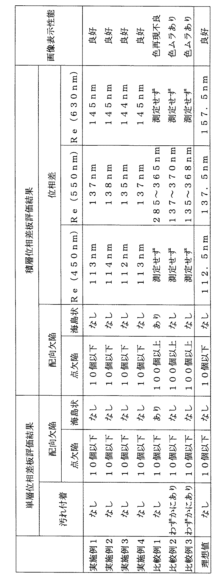
位相差板及び円偏光板の評価は以下に示す方法で行った。結果を表3中に示す。
(単層位相差板のラビング布への汚れ付着)
単層位相差板表面をラビングした後のラビング布の汚れ(白っぽく見える)を目視で評価した。
(単層位相差板の配向欠陥の評価)
表面をラビング処理する前の単層位相差板を、偏光顕微鏡下で観察し、配向欠陥の評価を行った。配向欠陥は、点欠陥と海島状の欠陥の2種類が観察される場合もあったため、点欠陥の個数と海島状欠陥の有無(両方とも1mm2における平均値として算出)を評価した。
(積層位相差板の配向欠陥の評価)
円偏光板とする前の積層位相差板を偏光顕微鏡下で観察し、配向欠陥の評価を行った。配向欠陥は、点欠陥と海島状の欠陥の2種類が観察される場合もあったため、点欠陥の個数と海島状欠陥の有無を評価した。
【0200】
(積層位相差板の位相差の測定及び面内ムラの評価)
積層位相差板を円偏光板とした後、円偏光板の偏光膜側(反射防止フィルム側)から光(測定波長は450nm、550nm、及び650nm)を照射し、通過した光の位相差(レターデーション値:Re)を測定した。また、面内に位相差の大きく異なるムラのある場合もあったため、該当する円偏光板は550nmのみのレターデーション値の最大値と最小値を測定した。
(円偏光板の画像表示性能の評価)
シャープ製ザウルスMI−E1の液晶セル以下を残して円偏光板部を含め上側を全てとりはずし、上記で作製した円偏光板を貼り付け、人物画像を表示した状態を目視で観察した。
【0201】
【表3】
表3に示す結果より、比較例1は単層及び積層とも海島状欠陥が発生し、更に光学異方性層(A)と光学異方性層(B)は目的の交差角で遅相軸が交差せずに所望の位相差の積層位相差板が得られなかった。従って、画像表示性能も不充分であった。比較例2及び3は、海島状欠陥は発生しないもののラビング布への汚れの付着があり、積層した場合は、点欠陥が多発した。更に所望の位相差は面内に部分的に発現するのみで、画像表示性能も不充分であった。これに対し、本発明の構成に従えば、ラビング布への汚れの付着もなく光学異方性層にラビング処理をすることが可能であり、配向欠陥の少ない安定した位相差板、円偏光板が作製できる。さらに、画像表示装置に取り付けた場合も良好な画像表示性能を得ることができる。
【0203】
【発明の効果】
本発明によれば、液晶化合物の配向を固定化した層を有する位相差板において、固定化後の表面がべとつかず、表面を布などで擦っても添加剤などが転写しない位相差板、及び該位相差板の作製に有用な液晶組成物を提供することができる。また、本発明によれば、液晶化合物の配向を固定化した層を複数有する位相差板において、上層の液晶化合物を配向させるための配向膜を実質的に用いずに液晶化合物の配向を規制し固定化する方法で作製可能な位相差板、及び該位相差板の作製に有用な液晶組成物を提供することができる。更には、該位相差板を用いた表示特性に優れた画像表示装置、及び画像表示装置の表示特性の向上に寄与する前記位相差板を用いた円偏光板を提供することができる。[0001]
BACKGROUND OF THE INVENTION
The present invention relates to a liquid crystal composition containing a liquid crystal compound and a retardation plate having an optically anisotropic layer using the liquid crystal composition. In the case where the retardation plate has two or more optically anisotropic layers, the invention relates to a retardation plate in which no alignment film layer is provided between the two optically anisotropic layers. Furthermore, the present invention relates to an image display device using these retardation plates.
[0002]
[Prior art]
A retardation plate made of an optically anisotropic material is a necessary material in an LCD display device. When one kind of material cannot achieve a desired optical performance, a plurality of optical materials may be used. For example, a λ / 4 plate is used in a reflection type liquid crystal display device, but in such a wavelength range of R, G, B, the phase difference of the λ / 4 plate is ¼ of the wavelength. However, it is difficult to satisfy such optical performance with a single material, and λ / 2 plates and λ / 4 plates are used. Each of these materials has a thickness of several tens of μm or more, and is used by sticking them together with an adhesive or the like. On the other hand, Japanese Patent Application Laid-Open No. 2001-4837 discloses a technique for producing a broadband λ / 4 plate by laminating two optically anisotropic layers made of a liquid crystalline compound on a long support. Also, US Pat. No. 6,160,597 discloses a technique for laminating layers obtained by immobilizing a liquid crystal compound, but an alignment film layer is separately formed between the layers obtained by immobilizing the liquid crystal compound. In such a laminating method, in order to apply a liquid crystal compound, it is necessary to apply an alignment film therefor. That is, in order to fix the alignment of the liquid crystal compound and form one optically anisotropic layer, the alignment film and the liquid crystal compound must be applied at least twice, resulting in high production costs. There was a need for inexpensive manufacturing technology. Furthermore, as the number of times of application increases, even if the probability of product failure due to application or liquid crystal compound orientation failure is the same, the number of defects in the completed retardation plate increases, and the target phase difference is increased. The yield of a board will worsen. Therefore, it is required to reduce the number of coatings from the viewpoint of increasing the yield at the time of manufacture.
[0003]
A technique for forming a surface layer by transferring an additive to the air interface side has been proposed, but in this technique, a surface active material is added to control the tilt alignment on the air interface side of the liquid crystal composition ( Patent Document 1). However, Patent Document 1 does not describe or suggest a technique for rubbing the surface layer on the air interface side to form an optically anisotropic layer made of a polymerizable liquid crystal composition. In addition, a technique of adding a surfactant as a leveling agent to smooth the surface of the polymerizable liquid crystal composition has been proposed (see Patent Documents 2 and 3). Patent Documents 2 and 3 describe that the function of the leveling agent is to reduce the surface tension of the liquid crystal composition, and reducing the surface tension can reduce optical unevenness due to film thickness unevenness. Has been. However, there is no description or suggestion regarding a technique for forming an optically anisotropic layer made of a polymerizable liquid crystal composition.
[0004]
We made one optically anisotropic layer composed of a polymerizable liquid crystal compound using the leveling agent described in Patent Document 3, and rubbed the surface, and then another optically anisotropic layer. Tried to form. However, it became clear that the surface of the first layer was sticky, the leveling agent was transferred to the rubbing cloth, and the orientation of the second optically anisotropic layer was insufficient.
[0005]
[Patent Document 1]
JP 2000-105315 A
[Patent Document 2]
JP-A-11-148080
[Patent Document 3]
JP-A-8-231958
[0006]
[Problems to be solved by the invention]
The problem to be solved by the present invention is that, in a retardation plate having a layer in which the orientation of a liquid crystal compound is fixed, the surface after fixation is not sticky, and the additive does not transfer even if the surface is rubbed with a cloth or the like. A retardation plate and a liquid crystal composition useful for producing the retardation plate are provided. In addition, in a retardation plate having a plurality of layers in which the alignment of the liquid crystal compound is fixed, the liquid crystal compound is prepared by a method that regulates and fixes the alignment of the liquid crystal compound without substantially using an alignment film for aligning the upper liquid crystal compound. It is an object to provide a possible retardation plate and a liquid crystal composition useful for producing the retardation plate. Furthermore, it is providing the image display apparatus excellent in the display characteristic using this phase difference plate, and the circularly-polarizing plate using the said phase difference plate which contributes to the improvement of the display characteristic of an image display apparatus.
[0007]
[Means for Solving the Problems]
The above problems have been achieved by the following means.
(1) A liquid crystal composition containing a liquid crystal compound and a non-liquid crystal polymer having a crosslinkable group.
(2) The liquid crystal composition according to (1), wherein the non-liquid crystalline polymer having a crosslinkable group is a polymer containing a repeating unit represented by the general formula (III).
[0008]
Formula (III)
[Chemical 1]
(In the general formula (III), R31Represents a hydrogen atom or an alkyl group having 1 to 4 carbon atoms. P31Is a monovalent group containing an ethylenically unsaturated group, L31Represents a single bond or a divalent linking group. )
[0010]
(3) In general formula (III), R31Is a hydrogen atom or a methyl group, and P31Is a monovalent group containing a group selected from an acryloyl group, a methacryloyl group and a styryl group, and L31Is an arylene group, * —COO—, * —CONH— or * —OCO— (* represents a position linked to the main chain).
(4) The δa value calculated using the three-dimensional SP value is any one of (1) to (3), wherein the δa value of the non-liquid crystalline polymer having a crosslinkable group is smaller than the δa value of the liquid crystalline compound The liquid crystal composition described in 1.
[0011]
(5) A retardation plate having at least one optically anisotropic layer formed from the liquid crystal composition according to any one of (1) to (4) on a transparent support.
(6) The transparent support has at least two optically anisotropic layers, and at least one optically anisotropic layer is formed from the liquid crystal composition according to any one of (1) to (4). A retardation plate having an optically anisotropic layer.
(7) The retardation plate according to (6), which has substantially no alignment film layer between at least two optically anisotropic layers.
(8) The angle formed by the slow axis of the lower layer of the optically anisotropic layer and the slow axis of the upper layer of the optically anisotropic layer is substantially 60 °, and one optically anisotropic layer has a wavelength of 550 nm. The phase difference plate according to (6) or (7), wherein the phase difference is substantially π and the phase difference of the other optically anisotropic layer at a wavelength of 550 nm is substantially π / 2.
[0012]
(9) The retardation plate according to (8) and a polarizing plate on a side of the retardation plate having a phase difference of substantially π at a wavelength of 550 nm, and the polarization transmission axis of the polarizing plate And a circularly polarizing plate having an angle of 15 ° or 75 ° formed by a slow axis of a layer having a phase difference of substantially π.
(10) An image display device having the retardation plate according to any one of (5) to (8) or the circularly polarizing plate according to (9).
[0013]
DETAILED DESCRIPTION OF THE INVENTION
Hereinafter, the present invention will be described in detail.
The liquid crystal composition of the present invention contains a liquid crystal compound (hereinafter also referred to as “liquid crystal molecule”) and a non-liquid crystal polymer having a crosslinkable group (hereinafter also referred to as “crosslinkable polymer”) as essential components. . The liquid crystal composition of the present invention is useful for forming an optically anisotropic layer composed of a liquid crystalline compound, and is useful for producing an optical member such as a retardation plate having the layer.
[0014]
The liquid crystalline molecules are preferably rod-shaped liquid crystalline molecules or discotic liquid crystalline molecules. The liquid crystalline molecules are preferably substantially uniformly aligned in the optically anisotropic layer, more preferably fixed in a substantially uniformly aligned state, and liquid crystallinity is obtained by a polymerization reaction. Most preferably, the molecule is immobilized. The orientation of the liquid crystalline molecules in the optically anisotropic layer is preferably an orientation in which the major axis of the molecule is substantially horizontal to the substrate (horizontal orientation). Both anisotropic layers are preferably horizontally oriented.
[0015]
Examples of rod-like liquid crystalline molecules include azomethines, azoxys, cyanobiphenyls, cyanophenyl esters, benzoic acid esters, cyclohexanecarboxylic acid phenyl esters, cyanophenylcyclohexanes, cyano-substituted phenylpyrimidines, alkoxy-substituted phenylpyrimidines. , Phenyldioxanes, tolanes and alkenylcyclohexylbenzonitriles are preferably used. In addition to the above low-molecular liquid crystalline molecules, high-molecular liquid crystalline molecules can also be used.
[0016]
It is more preferable to fix the orientation of the rod-like liquid crystalline molecules by polymerization, and examples of the polymerizable rod-like liquid crystalline molecules include those described in Makromol. Chem. 190, 2255 (1989), Advanced Materials 5, 107 (1993), U.S. Pat. Nos. 4,683,327, 5,622,648, 5,770,107, WO 95/22586, 95/24455, 97/97. No. 0600, No. 98/23580, No. 98/52905, JP-A-1-272551, JP-A-6-16616, JP-A-7-110469, JP-A-11-80081, and Japanese Patent Application No. 2001-64627 The compounds described in the publications and specifications can be used. More preferably, it is a compound represented by the following general formula (I).
[0017]
Formula (I)
Q1-L1-Cy1-L2-(Cy2-L3)n-Cy3-L4-Q2
Where Q1And Q2Are each independently a polymerizable group, L1And L4Are each independently a divalent linking group, L2And L3Are each independently a single bond or a divalent linking group, and Cy1, Cy2And Cy3Are each independently a divalent cyclic group, and n is 0, 1 or 2.
[0018]
Hereinafter, the polymerizable rod-like liquid crystal compound represented by the general formula (I) will be described.
Where Q1And Q2Are each independently a polymerizable group. The polymerization reaction of the polymerizable group is preferably addition polymerization (including ring-opening polymerization) or condensation polymerization. In other words, the polymerizable group is preferably a functional group capable of addition polymerization reaction or condensation polymerization reaction. Examples of polymerizable groups are shown below.
[0019]
[Chemical 2]
L1And L4Are each independently a divalent linking group. L1And L4Are each independently -O-, -S-, -CO-, -NR2It is preferably a divalent linking group selected from the group consisting of-, a divalent chain group, a divalent cyclic group, and combinations thereof. R above2Is an alkyl group having 1 to 7 carbon atoms or a hydrogen atom.
The example of the bivalent coupling group which consists of a combination is shown below. Here, the left side is Q (Q1Or Q2), The right side is Cy (Cy1Or Cy3).
[0021]
L-1: —CO—O—divalent chain group —O—
L-2: -CO-O-divalent chain group -O-CO-
L-3: —CO—O—divalent chain group —O—CO—O—
L-4: -CO-O-divalent chain group -O-divalent cyclic group-
L-5: -CO-O-divalent chain group -O-divalent cyclic group -CO-O-
L-6: -CO-O-divalent chain group -O-divalent cyclic group -O-CO-
L-7: -CO-O-divalent chain group-O-divalent cyclic group-divalent chain group-
L-8: -CO-O-divalent chain group -O-divalent cyclic group -divalent chain group -CO-O-
L-9: -CO-O-divalent chain group -O-divalent cyclic group -divalent chain group -O-CO-
L-10: —CO—O—divalent chain group—O—CO—divalent cyclic group—
L-11: -CO-O-divalent chain group -O-CO-divalent cyclic group -CO-O-
L-12: -CO-O-divalent chain group -O-CO-divalent cyclic group -O-CO-
L-13: —CO—O—Divalent chain group—O—CO—Divalent cyclic group—Divalent chain group—
L-14: -CO-O-divalent chain group -O-CO-divalent cyclic group -divalent chain group -CO-O-
L-15: -CO-O-divalent chain group-O-CO-divalent cyclic group-divalent chain group-O-CO-
L-16: —CO—O—divalent chain group—O—CO—O—divalent cyclic group—
L-17: -CO-O-divalent chain group -O-CO-O-divalent cyclic group -CO-O-
L-18: -CO-O-divalent chain group -O-CO-O-divalent cyclic group -O-CO-
L-19: —CO—O—Divalent chain group—O—CO—O—Divalent cyclic group—Divalent chain group—
L-20: -CO-O-divalent chain group -O-CO-O-divalent cyclic group -divalent chain group -CO-O-
L-21: -CO-O-divalent chain group -O-CO-O-divalent cyclic group -divalent chain group -O-CO-
[0022]
The divalent chain group means an alkylene group, a substituted alkylene group, an alkenylene group, a substituted alkenylene group, an alkynylene group, or a substituted alkynylene group. An alkylene group, a substituted alkylene group, an alkenylene group and a substituted alkenylene group are preferred, and an alkylene group and an alkenylene group are more preferred.
The alkylene group may have a branch. The alkylene group preferably has 1 to 12 carbon atoms, more preferably 2 to 10 carbon atoms, and most preferably 2 to 8 carbon atoms.
The alkylene part of the substituted alkylene group is the same as the above alkylene group. Examples of the substituent include a halogen atom.
The alkenylene group may have a branch. The alkenylene group preferably has 2 to 12 carbon atoms, more preferably 2 to 10 carbon atoms, and most preferably 2 to 8 carbon atoms.
The alkylene part of the substituted alkylene group is the same as the above alkylene group. Examples of the substituent include a halogen atom.
The alkynylene group may have a branch. The alkynylene group preferably has 2 to 12 carbon atoms, more preferably 2 to 10 carbon atoms, and most preferably 2 to 8 carbon atoms.
The alkynylene part of the substituted alkynylene group is the same as the above alkynylene group. Examples of the substituent include a halogen atom.
Specific examples of the divalent chain group include ethylene, trimethylene, propylene, tetramethylene, 2-methyl-tetramethylene, pentamethylene, hexamethylene, octamethylene, 2-butenylene, 2-butynylene and the like.
The definition and examples of the divalent cyclic group are described later in Cy.1, Cy2And Cy3This is the same as the definition and example in FIG.
[0023]
L1And L4-NR represented by2-R2Is preferably an alkyl group having 1 to 4 carbon atoms or a hydrogen atom, more preferably a methyl group, an ethyl group or a hydrogen atom, and most preferably a hydrogen atom.
[0024]
L2And L3Are each independently a single bond or a divalent linking group. L2And L3Are each independently -O-, -S-, -CO-, -NR2It is preferably a divalent linking group or a single bond selected from the group consisting of-, a divalent chain group, a divalent cyclic group and combinations thereof. R above2Is an alkyl group having 1 to 7 carbon atoms or a hydrogen atom, preferably an alkyl group having 1 to 4 carbon atoms or a hydrogen atom, more preferably a methyl group, an ethyl group or a hydrogen atom, Most preferably, it is a hydrogen atom. L for a divalent chain group and a divalent cyclic group1And L4It is synonymous with the definition of
[0025]
In the formula (I), n is 0, 1 or 2. If n is 2, then two L3May be the same or different, and two Cy2May be the same or different. n is preferably 1 or 2, and more preferably 1.
[0026]
In formula (I), Cy1, Cy2And Cy3Are each independently a divalent cyclic group.
The ring contained in the cyclic group is preferably a 5-membered ring, a 6-membered ring, or a 7-membered ring, more preferably a 5-membered ring or a 6-membered ring, and most preferably a 6-membered ring. The ring contained in the cyclic group may be a condensed ring. However, it is more preferably a monocycle than a condensed ring.
The ring contained in the cyclic group may be any of an aromatic ring, an aliphatic ring, and a heterocyclic ring. Examples of the aromatic ring include a benzene ring and a naphthalene ring. Examples of the aliphatic ring include a cyclohexane ring. Examples of the heterocyclic ring include a pyridine ring and a pyrimidine ring.
As the cyclic group having a benzene ring, 1,4-phenylene is preferable. As the cyclic group having a naphthalene ring, naphthalene-1,5-diyl and naphthalene-2,6-diyl are preferable. The cyclic group having a cyclohexane ring is preferably 1,4-cyclohexylene. As the cyclic group having a pyridine ring, pyridine-2,5-diyl is preferable. The cyclic group having a pyrimidine ring is preferably pyrimidine-2,5-diyl.
The cyclic group may have a substituent. Examples of the substituent include a halogen atom, a cyano group, a nitro group, an alkyl group having 1 to 5 carbon atoms, a halogen-substituted alkyl group having 1 to 5 carbon atoms, and an alkoxy group having 1 to 5 carbon atoms. , An alkylthio group having 1 to 5 carbon atoms, an acyloxy group having 2 to 6 carbon atoms, an alkoxycarbonyl group having 2 to 6 carbon atoms, a carbamoyl group, and an alkyl-substituted carbamoyl group having 2 to 6 carbon atoms And an acylamino group having 2 to 6 carbon atoms.
[0027]
Examples of the polymerizable liquid crystal compound represented by the formula (I) are shown below. The present invention is not limited to these.
[0028]
[Chemical 3]
[Formula 4]
[Chemical formula 5]
[Chemical 6]
Next, preferred discotic liquid crystal molecules will be described. Discotic liquid crystalline molecules are disclosed in various literatures (C. Destrade et al., Mol. Crysr. Liq. Cryst., Vol. 71, page 111 (1981); edited by The Chemical Society of Japan, Quarterly Review, No. 22, Liquid Crystal Chemistry, Chapter 5, Chapter 10 Section 2 (1994); B. Kohne et al., Angew. Chem. Soc. Chem. Comm., Page 1794 (1985); J. Zhang et al., J Am.Chem.Soc., Vol.116, page 2655 (1994)). The polymerization of discotic liquid crystalline molecules is described in JP-A-8-27284. In order to fix the discotic liquid crystalline molecules by polymerization, it is necessary to bond a polymerizable group as a substituent to the discotic core of the discotic liquid crystalline molecules. However, when the polymerizable group is directly connected to the disc-shaped core, it becomes difficult to maintain the orientation state in the polymerization reaction. Therefore, a linking group is introduced between the discotic core and the polymerizable group. Accordingly, the discotic liquid crystalline molecule having a polymerizable group is preferably a compound represented by the following formula (II).
[0033]
Formula (II) D (-LP)n
Where D is a discotic core; L is a divalent linking group; P is a polymerizable group; and n is an integer from 4 to 12. Examples of the discotic core (D) of the formula (II) are shown below. In each of the following examples, LP (or PL) means a combination of a divalent linking group (L) and a polymerizable group (P).
[0034]
[Chemical 7]
[Chemical 8]
[Chemical 9]
Embedded image
Embedded image
Embedded image
Embedded image
Embedded image
In the formula (II), the divalent linking group (L) is selected from the group consisting of an alkylene group, an alkenylene group, an arylene group, —CO—, —NH—, —O—, —S—, and combinations thereof. A divalent linking group is preferred. The divalent linking group (L) is a group obtained by combining at least two divalent groups selected from the group consisting of an alkylene group, an alkenylene group, an arylene group, -CO-, -NH-, -O-, and S-. More preferably. The divalent linking group (L) is most preferably a group obtained by combining at least two divalent groups selected from the group consisting of an alkylene group, an alkenylene group, an arylene group, -CO- and O-. The alkylene group preferably has 1 to 12 carbon atoms. The alkenylene group preferably has 2 to 12 carbon atoms. The number of carbon atoms in the arylene group is preferably 6-10. The alkylene group, alkenylene group and arylene group may have a substituent (eg, alkyl group, halogen atom, cyano, alkoxy group, acyloxy group).
[0043]
Examples of the divalent linking group (L) are shown below. The left side is bonded to the discotic core (D), and the right side is bonded to the polymerizable group (P). AL represents an alkylene group or an alkenylene group, and AR represents an arylene group.
L1: -AL-CO-O-AL-
L2: -AL-CO-O-AL-O-
L3: -AL-CO-O-AL-O-AL-
L4: -AL-CO-O-AL-O-CO-
L5: -CO-AR-O-AL-
L6: -CO-AR-O-AL-O-
L7: -CO-AR-O-AL-O-CO-
L8: -CO-NH-AL-
L9: -NH-AL-O-
L10: -NH-AL-O-CO-
[0044]
L11: -O-AL-
L12: -O-AL-O-
L13: -O-AL-O-CO-
L14: -O-AL-O-CO-NH-AL-
L15: -O-AL-S-AL-
L16: -O-CO-AL-AR-O-AL-O-CO-
L17: -O-CO-AR-O-AL-CO-
L18: -O-CO-AR-O-AL-O-CO-
L19: -O-CO-AR-O-AL-O-AL-O-CO-
L20: -O-CO-AR-O-AL-O-AL-O-AL-O-CO-
L21: -S-AL-
L22: -S-AL-O-
L23: -S-AL-O-CO-
L24: -S-AL-S-AL-
L25: -S-AR-AL-
[0045]
The polymerizable group (P) of the formula (II) is determined according to the type of polymerization reaction. Examples of the polymerizable group (P) are shown below.
[0046]
Embedded image
Embedded image
Embedded image
Embedded image
Embedded image
Embedded image
The polymerizable group (P) is preferably an unsaturated polymerizable group (P1, P2, P3, P7, P8, P15, P16, P17) or an epoxy group (P6, P18). More preferably, it is most preferably an ethylenically unsaturated polymerizable group (P1, P7, P8, P15, P16, P17). In formula (II), n is an integer of 4-12. A specific number is determined according to the type of discotic core (D). In addition, although the combination of several L and P may differ, it is preferable that it is the same. Two or more kinds of discotic liquid crystalline molecules (for example, a molecule having an asymmetric carbon atom in a divalent linking group and a molecule not having it) may be used in combination.
[0053]
The crosslinkable polymer contained in the liquid crystal composition of the present invention means a polymer having a crosslinkable group (polymerizable group) and having no liquid crystallinity (non-liquid crystallinity), and supporting the liquid crystal composition. When a retardation plate is produced by forming an optically anisotropic layer by coating on a body, it has a leveling function of smoothing the surface of the air interface of the optically anisotropic layer. Furthermore, it has a function in place of an alignment film formed between optically anisotropic layers, which has been required in the past when a retardation plate having a plurality of optically anisotropic layers is produced. That is, the crosslinkable polymer moves to the air interface side of the optically anisotropic layer to form a surface concentrated layer containing a large amount of the crosslinkable polymer, and the surface concentrated layer is imparted with an alignment function by rubbing or the like. It has a function as an alignment film for aligning a liquid crystalline compound to be an anisotropic layer. Therefore, the upper optically anisotropic layer can be provided without using an alignment film between at least two optically anisotropic layers. Further, at this time, it is preferable that a lower optical anisotropic layer is rubbed to further provide an upper optical anisotropic layer. In addition, the crosslinkable polymer can suppress the surface stickiness of the optically anisotropic layer by crosslinking the crosslinkable group. When forming the upper optically anisotropic layer, it can be used as a liquid crystalline compound and a coating solvent to be used. On the other hand, it becomes possible to impart dissolution resistance and remarkably improve the alignment film function.
[0054]
In order to exhibit the above viewpoint, that is, sufficient leveling function and sufficient surface concentration layer forming property, the crosslinkable polymer used in the liquid crystal composition of the present invention is hydrophobic to the liquid crystal compound used. High is preferred. A surface concentrated layer can be formed by greatly increasing the hydrophobicity of the crosslinkable polymer. However, the crosslinkable polymer itself does not have liquid crystallinity.
[0055]
The hydrophilicity / hydrophobicity of the crosslinkable polymer and the liquid crystal compound used in the present invention can be predicted from the compound structure using various methods, and a log P value, an I / O value, an SP value, and the like can be used. The non-dispersive force component of the SP value calculated by the method of Hoy et al. (See VAN KREVELEEN, DW, “PROPERITES OF POLYMERS (ED.3)” ELSEVIER publication (1990)) by the study of the present inventors. It was found that by obtaining (referred to as δa value in the present invention), the expression of the leveling function and the surface concentrated layer forming property of the crosslinkable polymer in the present invention can be estimated. The δa value can be calculated by the following formula (1) using the three-dimensional SP values (δd, δp, δh) calculated by the method of Hoy et al. According to the method of Hoy et al., Each value of δd, δp, and δh can be calculated from the chemical structural formula of the desired compound. In the case of a copolymer composed of a plurality of repeating units, the square value of the three-dimensional SP value for each repeating unit (δd2, Δp2, Δh2) Multiplied by the volume fraction of each repeating unit to obtain the sum, the square value of the three-dimensional SP value of the copolymer (δd2, Δp2, Δh2) And substituting this into equation (1), the δa value of the copolymer can be determined.
δa = (δp2 + Δh2 )0.5 Formula (1)
[0056]
The δa value of the crosslinkable polymer used in the present invention is preferably smaller than the δa value of the liquid crystalline compound used for forming the leveling function and forming the surface concentrated layer. Furthermore, it is preferable that the difference is large, and it is preferable that the value obtained by subtracting the δa value of the crosslinkable polymer used in the present invention from the δa value of the liquid crystal compound is positively large, and the subtracted value is 1.5 or more. Is preferred. The preferable range of the value obtained by subtracting the δa value of the crosslinkable polymer from the δa value of the liquid crystal compound is the type and molecular weight of the liquid crystal compound used and the crosslinkable polymer, and the temperature and time during the alignment treatment that is heated as necessary. 0.5 to 20 MPa, depending on0.5Is preferred, 1.0-20 MPa0.5Is more preferable, 2.0-20MPa0.5Is most preferred.
[0057]
The crosslinkable group contained in the crosslinkable polymer can be used without particular limitation such as an addition, condensation, and substitution reactive group. On the other hand, the liquid crystalline compound itself is preferably introduced by introducing an ethylenically unsaturated group such as an acryloyl group or a methacryloyl group, and fixed by irradiation with ultraviolet rays using a photo radical polymerization initiator, and the crosslinkable polymer is also crosslinked by irradiation with ultraviolet rays. It preferably has a crosslinkable group. Preferred examples of reactions that can be cross-linked by UV irradiation include ring-opening polymerization reactions of heterocyclic compounds such as epoxy rings and oxetane rings combined with compounds that generate cations by UV irradiation, and compounds that generate radicals by UV irradiation A radical polymerization reaction of a compound having an ethylenically unsaturated group. The most preferred crosslinkable group contained in the crosslinkable polymer is an ethylenically unsaturated group.
[0058]
The polymer forming reaction of the crosslinkable polymer is not particularly limited, such as addition, condensation, and substitution reaction, but radical polymerization reaction of an ethylenically unsaturated compound is the simplest and preferable. In the present invention, it is particularly preferable to use a crosslinkable polymer having a repeating unit represented by the following general formula (III).
[0059]
Formula (III)
Embedded image
In general formula (III), R31Represents a hydrogen atom or an alkyl group having 1 to 4 carbon atoms, preferably a hydrogen atom or a methyl group. P31Is a monovalent group containing an ethylenically unsaturated group, L31Is a single bond or a divalent linking group, preferably a single bond, -O-, an alkylene group, an arylene group, and * -COO-, * -CONH-, * -OCO- linked to the main chain on the * side, * —NHCO—. P31Is a monovalent group containing an ethylenically unsaturated group. Preferred P31Is a monovalent group containing a group selected from an acryloyl group, a methacryloyl group and a styryl group, and most preferably a monovalent group containing a group selected from an acryloyl group and a methacryloyl group.
[0061]
In general formula (III), preferred combinations include R31Is a hydrogen atom or a methyl group; L31Is an arylene group, * —COO—, * —CONH—, or * —OCO—; P31Is a monovalent group including a group selected from an acryloyl group, a methacryloyl group, and a styryl group.
[0062]
Although the preferable specific example of the repeating unit represented by general formula (III) below is shown, this invention is not limited to these.
[0063]
Embedded image
Embedded image
Embedded image
Embedded image
Embedded image
The crosslinkable polymer containing the repeating unit represented by the general formula (III) may be synthesized by (a) a method in which a corresponding monomer is polymerized to directly introduce an ethylenically unsaturated group, and (b) You may synthesize | combine by the method of introduce | transducing an ethylenically unsaturated group into a polymer obtained by superposing | polymerizing the monomer which has a functional group by polymer reaction. Moreover, it can also synthesize | combine combining the method of (a) and (b). Examples of the polymerization reaction that can be used in the methods (a) and (b) include radical polymerization, cationic polymerization, and anionic polymerization. When the method (a) is used, it is necessary to use the difference in polymerizability between the ethylenically unsaturated group consumed by the polymerization reaction and the ethylenically unsaturated group remaining as a crosslinkable group in the crosslinkable polymer. It is. For example, preferred P of general formula (III)31Among them, when a monovalent group containing an acryloyl group or a methacryloyl group is used, the crosslinkable polymer of the present invention can be obtained by the method of (a) above by setting the polymerization reaction for generating a crosslinkable polymer to cationic polymerization. Can be obtained. On the other hand, P31Is a monovalent group containing a styryl group, gelation is likely to proceed by any of radical polymerization, cationic polymerization and anionic polymerization. Therefore, the crosslinkable polymer of the present invention is usually prepared by the method (b). It is preferable to synthesize.
[0069]
As described above, the method utilizing the polymer reaction described in the above (b) is not limited to the type of the ethylenically unsaturated group introduced into the crosslinkable polymer represented by the general formula (III). Can be obtained and is useful. The polymer reaction is, for example, I) For example, after forming a polymer containing a functional group obtained by precuring an ethylenically unsaturated group that removes hydrochloric acid from a 2-chloroethyl group, functional group conversion (elimination reaction, oxidation) A method in which an ethylenically unsaturated group is derived by a reaction, a reduction reaction, a deprotection reaction, etc.), and II) after a polymer containing an arbitrary functional group is formed, a bond formation reaction with the functional group in the polymer proceeds. And a compound having both a functional group capable of forming a covalent bond and an ethylenically unsaturated group (hereinafter referred to as “reactive monomer”). Moreover, you may carry out combining the method of said I) and said II). The bond formation reaction mentioned here can be used without particular limitation as long as it is a reaction that forms a covalent bond among the bond formation reactions generally used in the field of organic synthesis. On the other hand, since the ethylenically unsaturated group contained in the crosslinkable polymer may be thermally polymerized and gelled during the reaction, the reaction proceeds at the lowest possible temperature (preferably 60 ° C. or less, particularly preferably room temperature or less). Those that do are preferred. A catalyst may be used for the purpose of promoting the progress of the reaction, and a polymerization inhibitor may be used for the purpose of suppressing gelation.
[0070]
Although the preferable example of the combination of the functional group which polymer bond formation reaction advances below is given, this invention is not limited to these.
As a combination of functional groups that the reaction proceeds at heating or room temperature,
(A) With respect to the hydroxyl group, an epoxy group, an isocyanate group, an N-methylol group, a carboxyl group, an alkyl halide, an acid anhydride, an acid chloride, an active ester group (for example, a sulfate ester), a formyl group, an acetal group;
(B) Hydroxyl group, mercapto group, amino group, carboxyl group, N-methylol group with respect to isocyanate group;
(C) An epoxy group, an isocyanate group, an amino group, an N-methylol group with respect to the carboxyl group;
(D) Isocyanate group, N-methylol group, carboxyl group, amino group, hydroxyl group with respect to N-methylol group;
(E) Hydroxyl group, amino group, mercapto group, carboxyl group, N-methylol group with respect to epoxy group;
(F) a vinylsulfone group, a sulfinic acid group, an amino group;
(G) hydroxyl group, mercapto group, active methylene group with respect to formyl group;
(H) For mercapto group, formyl group, vinyl group (allyl group, acrylic group, etc.), epoxy group, isocyanate group, N-methylol group, carboxyl group, alkyl halide, acid anhydride, acid chloride, active ester group (Eg sulfate esters);
(Li) Amino group, formyl group, vinyl group (allyl group, acrylic group, etc.), epoxy group, isocyanate group, N-methylol group, carboxyl group, alkyl halide, acid anhydride, acid chloride, active ester group (For example, sulfate ester);
[0071]
Although the preferable specific example of a reactive monomer is shown below, this invention is not limited to these.
Hydroxyl group-containing vinyl monomers (eg, hydroxyethyl acrylate, hydroxyethyl methacrylate, allyl alcohol, hydroxypropyl acrylate, hydroxypropyl methacrylate, etc.), isocyanate group-containing vinyl monomers (eg, isocyanatoethyl acrylate, isocyanatoethyl methacrylate, etc.), N -Methylol group-containing vinyl monomers (for example, N-methylol acrylamide, N-methylol methacrylamide, etc.), epoxy group-containing vinyl monomers (for example, glycidyl acrylate, glycidyl methacrylate, allyl glycidyl ether, CYCLOMER-M100, A200 (Daicel Chemical Industries ( Etc.)), carboxyl group-containing vinyl monomers (eg acrylic acid, methacrylate) Acid, itaconic acid, carboxyethyl acrylate, vinyl benzoate), alkyl halide-containing vinyl monomers (for example, chloromethylstyrene, 2-hydroxy-3-chloropropyl methacrylate), acid anhydride-containing vinyl monomers (for example, maleic anhydride) , Formyl group-containing vinyl monomers (eg acrolein, methacrolein), sulfinic acid group-containing vinyl monomers (eg potassium styrenesulfinate), active methylene-containing vinyl monomers (eg acetoacetoxyethyl methacrylate), vinyl group-containing vinyl monomers (eg allyl methacrylate) , Allyl acrylate), acid chloride-containing monomers (for example, acrylic acid chloride, methacrylic acid chloride), amino group-containing monomers (for example, allylamine), and the like. That.
[0072]
The polymer containing any functional group described in II) is obtained by polymerization of a reactive monomer having both a reactive functional group and an ethylenically unsaturated group. Moreover, it can also obtain by performing functional group conversion after superposition | polymerization of a precursor monomer with low reactivity like polyvinyl alcohol obtained by modify | denaturating polyvinyl acetate. As a polymerization method in these cases, radical polymerization is the simplest and preferable.
[0073]
The crosslinkable polymer containing the repeating unit represented by the general formula (III) may be a copolymer composed of a plurality of types of repeating units represented by the general formula (III). ) May be a copolymer containing a repeating unit other than (for example, a repeating unit not containing an ethylenically unsaturated group). In particular, when it is desired to control the Tg or hydrophilicity / hydrophobicity of the crosslinkable polymer, or to control the content of the ethylenically unsaturated group of the crosslinkable polymer, a repeating unit other than the general formula (III) is introduced. preferable. As a method for introducing the repeating unit other than the general formula (III), (a) a method of directly introducing the corresponding monomer by copolymerization may be used, and (b) a precursor monomer capable of functional group conversion is polymerized. Alternatively, a method of introducing by polymer reaction may be used. Moreover, it can also introduce combining the method of (a) and (b).
[0074]
When the repeating unit other than the general formula (III) is introduced by the method (a), that is, by polymerizing the corresponding vinyl monomer or the like, the monomer preferably used is acrylic acid or α-alkylacrylic. Esters or amides derived from acids (such as methacrylic acid) (for example, Ni-propylacrylamide, Nn-butylacrylamide, Nt-butylacrylamide, N, N-dimethylacrylamide, N- Methylmethacrylamide, acrylamide, 2-acrylamido-2-methylpropanesulfonic acid, acrylamidopropyltrimethylammonium chloride, methacrylamide, diacetoneacrylamide, acryloylmorpholine, N-methylolacrylamide, N-methylo Methacrylamide, methyl acrylate, ethyl acrylate, hydroxyethyl acrylate, n-propyl acrylate, i-propyl acrylate, 2-hydroxypropyl acrylate, 2-methyl-2-nitropropyl acrylate, n-butyl acrylate, i-butyl acrylate, t-butyl acrylate, t-pentyl acrylate, 2-methoxyethyl acrylate, 2-ethoxyethyl acrylate, 2-methoxymethoxyethyl acrylate, 2,2,2-trifluoroethyl acrylate, 2,2-dimethylbutyl acrylate, 3- Methoxybutyl acrylate, ethyl carbitol acrylate, phenoxyethyl acrylate, n-pentyl acrylate, 3-pentyl acrylate, octafluorope Nthyl acrylate, n-hexyl acrylate, cyclohexyl acrylate, cyclopentyl acrylate, cetyl acrylate, benzyl acrylate, n-octyl acrylate, 2-ethylhexyl acrylate, 4-methyl-2-propylpentyl acrylate, heptadecafluorodecyl acrylate, n-octadecyl Acrylate, methyl methacrylate, 2,2,2-trifluoroethyl methacrylate, tetrafluoropropyl methacrylate, hexafluoropropyl methacrylate, hydroxyethyl methacrylate, 2-hydroxypropyl methacrylate, n-butyl methacrylate, i-butyl methacrylate, sec-butyl methacrylate , N-octyl methacrylate, 2-ethylhexyl methacrylate 2-methoxyethyl methacrylate, 2-ethoxyethyl methacrylate, benzyl methacrylate, heptadecafluorodecyl methacrylate, n-octadecyl methacrylate, 2-isobornyl methacrylate, 2-norbornylmethyl methacrylate, 5-norbornene-2- Ylmethyl methacrylate, 3-methyl-2-norbornylmethyl methacrylate, dimethylaminoethyl methacrylate, etc.), acrylic acid or α-alkyl acrylic acid (acrylic acid, methacrylic acid, itaconic acid, etc.), vinyl esters (eg, vinyl acetate) ), Esters derived from maleic acid or fumaric acid (such as dimethyl maleate, dibutyl maleate, diethyl fumarate), maleimides (such as N-phenylmaleimide), maleic acid , Fumaric acid, sodium salt of p-styrenesulfonic acid, acrylonitrile, methacrylonitrile, dienes (for example, butadiene, cyclopentadiene, isoprene), aromatic vinyl compounds (for example, styrene, p-chlorostyrene, t-butylstyrene, α -Methylstyrene, sodium styrenesulfonate), N-vinylpyrrolidone, N-vinyloxazolidone, N-vinylsuccinimide, N-vinylformamide, N-vinyl-N-methylformamide, N-vinylacetamide, N-vinyl-N -Methylacetamide, 1-vinylimidazole, 4-vinylpyridine, vinyl sulfonic acid, sodium vinyl sulfonate, sodium allyl sulfonate, sodium methallyl sulfonate, vinylidene chloride, vinyl alkyl ethers Such as methyl vinyl ether), ethylene, propylene, 1-butene, isobutene and the like. Two or more of these vinyl monomers may be used in combination. Vinyl monomers other than these are listed in Research Disclosure No. Those described in 1955 (1980, July) can be used. In the present invention, esters derived from acrylic acid or methacrylic acid, amides, and aromatic vinyl compounds are particularly preferably used vinyl monomers.
[0075]
In addition, when the crosslinkable group in the repeating unit represented by the general formula (III) is introduced by a polymer reaction by the method (b) and the reaction is not completed, the ethylenically unsaturated group is converted into a precursor. The copolymer has a repeating unit containing a functional group or a reactive functional group, but can be used without particular limitation in the present invention.
[0076]
Most of the repeating units that do not contain an ethylenically unsaturated group derived from the vinyl monomers listed above are polymerized by a precursor monomer that can be converted into a functional group by the method (b) described above, and polymer reaction. It is also possible to introduce. On the other hand, the crosslinkable polymer containing the repeating unit represented by the general formula (III) may contain a repeating unit other than the general formula (III) that can be introduced only by a polymer reaction. Typical examples include polyvinyl alcohol obtained by modifying polyvinyl acetate, polyvinyl butyral obtained by acetalization reaction of polyvinyl alcohol, and the like. Specific examples of these repeating units are shown below, but the present invention is not limited thereto.
[0077]
Embedded image
The crosslinkable polymer containing the repeating unit represented by the general formula (III) preferably contains 0.5% by mass to 100% by mass of the repeating unit represented by the general formula (III). It is more preferably 2% by mass or more and 100% by mass or less, and further preferably 5% by mass or more and 100% by mass or less.
[0079]
A preferred molecular weight range of the crosslinkable polymer containing the repeating unit represented by the general formula (III) is 1,000 to 1,000,000, more preferably 3000 to 200,000, and most preferably 5000 to 10 in terms of weight average molecular weight. Ten thousand.
[0080]
Although the preferable example of the crosslinkable polymer containing the repeating unit represented by the said general formula (III) below is shown in Table 1, this invention is not limited to this. In addition, the repeating unit represented by the above general formula (III) and the repeating unit such as polyvinyl alcohol, which are given as specific examples above, are represented by the numbers of the specific examples given above and are derived from a copolymerizable monomer. The repeating unit is described with the monomer name, and the copolymer composition ratio is indicated by mass%.
[0081]
[Table 1]
The content of the crosslinkable polymer contained in the liquid crystal composition of the present invention is preferably less than the liquid crystal compound (the main component is a liquid crystal compound) so as not to impair the optical properties, and the total mass of the liquid crystal compound is It is 0.01-20 mass% with respect to it, More preferably, it is 0.1-10 mass%, Most preferably, it is 0.5-5 mass%. In addition, a plurality of types of crosslinkable polymers may be included at the same time, and may be used in combination with a polymer having no crosslinkable group as long as the effects of the present invention are not impaired.
[0083]
The retardation plate of the present invention comprises a support (preferably a coating liquid containing a liquid crystalline compound such as a rod-like liquid crystalline molecule or a discotic liquid crystalline molecule, a crosslinkable polymer, and optionally a polymerizable initiator or other additives. Is provided with an alignment film) and has at least one layer formed by aligning and fixing the liquid crystalline compound. The layer can also be used by separating and fixing the liquid crystalline compound from the support after aligning and fixing. In preparing the coating solution, a solvent may be used, and an organic solvent is preferably used. Examples of organic solvents include amides (eg, N, N-dimethylformamide), sulfoxides (eg, dimethyl sulfoxide), heterocyclic compounds (eg, pyridine), hydrocarbons (eg, benzene, hexane), alkyl halides (eg, , Chloroform, dichloromethane), esters (eg, methyl acetate, butyl acetate), ketones (eg, acetone, methyl ethyl ketone, methyl isobutyl ketone, cyclohexanone), ethers (eg, tetrahydrofuran, 1,2-dimethoxyethane). Alkyl halides and ketones are preferred. Two or more organic solvents may be used in combination. Examples of the coating method include known coating methods such as curtain coating, dip coating, spin coating, printing coating, spray coating, slot coating, roll coating, slide coating, blade coating, gravure coating, and wire bar method.
[0084]
The aligned liquid crystal molecules are preferably fixed while maintaining the alignment state. The immobilization is preferably performed by a polymerization reaction of the polymerizable group (P) introduced into the liquid crystal molecule. The polymerization reaction includes a thermal polymerization reaction using a thermal polymerization initiator and a photopolymerization reaction using a photopolymerization initiator, and a photopolymerization reaction is preferred. Examples of polymerization initiators that generate radicals by the action of light include α-carbonyl compounds (described in US Pat. Nos. 2,367,661 and 2,367,670), acyloin ethers (described in US Pat. No. 2,448,828), α -Combination of hydrocarbon-substituted aromatic acyloin compound (described in US Pat. No. 2,722,512), polynuclear quinone compound (described in US Pat. Nos. 3,046,127 and 2,951,758), triarylimidazole dimer and p-aminophenyl ketone (Described in US Pat. No. 3,549,367), acridine and phenazine compounds (JP-A-60-105667, US Pat. No. 4,239,850) and oxadiazole compounds (described in US Pat. No. 4,221,970), acetophenone compounds , Benzoy Preferred are ether ether compounds, benzyl compounds, benzophenone compounds, thioxanthone compounds, and the like. Examples of the acetophenone compound include 2,2-diethoxyacetophenone, 2-hydroxymethyl-1-phenylpropan-1-one, 4′-isopropyl-2-hydroxy-2-methyl-propiophenone, 2-hydroxy -2-methyl-propiophenone, p-dimethylaminoacetone, p-tert-butyldichloroacetophenone, p-tert-butyltrichloroacetophenone, p-azidobenzalacetophenone and the like. Examples of the benzyl compound include benzyl, benzyl dimethyl ketal, benzyl-β-methoxyethyl acetal, 1-hydroxycyclohexyl phenyl ketone and the like. Examples of benzoin ether compounds include benzoin, benzoin methyl ether, benzoin ethyl ether, benzoin-n-propyl ether, benzoin isopropyl ether, benzoin-n-butyl ether, and benzoin isobutyl ether. Examples of the benzophenone compounds include benzophenone, methyl o-benzoylbenzoate, Michler's ketone, 4,4'-bisdiethylaminobenzophenone, 4,4'-dichlorobenzophenone, and the like. Examples of the thioxanthone compound include thioxanthone, 2-methylthioxanthone, 2-ethylthioxanthone, 2-isopropylthioxanthone, 4-isopropylthioxanthone, 2-chlorothioxanthone, 2,4-diethylthioxanthone, and the like. Among such photosensitive radical polymerization initiators composed of aromatic ketones, acetophenone compounds and benzyl compounds are particularly preferable in terms of curing characteristics, storage stability, odor, and the like. The photosensitive radical polymerization initiators composed of these aromatic ketones can be used alone or in combination of two or more according to the desired performance. In addition to a polymerization initiator, a sensitizer may be used for the purpose of increasing sensitivity. Examples of the sensitizer include n-butylamine, triethylamine, tri-n-butylphosphine, thioxanthone and the like.
[0085]
Multiple photopolymerization initiators may be combined, and the amount used is preferably 0.01 to 20% by mass, more preferably 0.5 to 5% by mass, based on the solid content of the coating solution. It is preferable to use ultraviolet rays for light irradiation for polymerization of liquid crystalline molecules. Irradiation energy is 20mJ / cm2~ 50J / cm2It is preferably 100 to 800 mJ / cm.2More preferably. In order to accelerate the photopolymerization reaction, light irradiation may be performed under heating conditions. The thickness of the optically anisotropic layer is preferably 0.1 to 10 μm, and more preferably 0.5 to 5 μm.
[0086]
When the retardation plate of the present invention is used without removing the support, for example, it is preferable to use a polymer film that is transparent, has a small optical anisotropy, and has a small wavelength dispersion as the support. Here, that the support is transparent means that the light transmittance is 80% or more. Specifically, the small chromatic dispersion means that the ratio of Re400 / Re700 is preferably less than 1.2. Specifically, the small optical anisotropy means that in-plane retardation (Re) is preferably 20 nm or less, and more preferably 10 nm or less. The transparent support preferably has a roll-like or rectangular sheet-like shape. The roll-like transparent support is used to laminate the optically anisotropic layer and then cut into a required size. preferable. Examples of the polymer include cellulose ester, polycarbonate, polysulfone, polyethersulfone, polyacrylate and polymethacrylate. Cellulose esters are preferred, acetyl cellulose is more preferred, and triacetyl cellulose is most preferred. The polymer film is preferably formed by a solvent cast method. The thickness of the transparent support is preferably 20 to 500 μm, and more preferably 50 to 200 μm. In order to improve the adhesion between the transparent support and the layer (adhesive layer, alignment film or optically anisotropic layer) provided on the transparent support, surface treatment (eg, glow discharge treatment, corona discharge treatment, ultraviolet light ( UV) treatment, flame treatment). An adhesive layer (undercoat layer) may be provided on the transparent support.
[0087]
In order to align the liquid crystalline compound on the support, it is preferable to use an alignment film. The alignment film may be an organic compound (for example, ω-triconic acid) formed by rubbing treatment of an organic compound (preferably a polymer), oblique deposition of an inorganic compound, formation of a layer having a micro group, or Langmuir-Blodgett method (LB film). , Dioctadecyldimethylammonium chloride, methyl stearylate, etc.). Furthermore, an alignment film in which an alignment function is generated by application of an electric field, application of a magnetic field, or light irradiation is also known. An alignment film formed by a polymer rubbing treatment is particularly preferable. The rubbing treatment can be performed by rubbing the surface of the polymer layer with paper or cloth several times in a certain direction.
[0088]
The rod-like liquid crystalline molecules can be oriented substantially horizontally (average inclination angle in the range of 0 to 30 degrees) with respect to the coating plane, or can be substantially oblique (average inclination angle in the range of 30 to 70 degrees). Orientation can be oriented substantially vertically (average tilt angle in the range of 50 to 90 degrees), or hybrid orientation (for example, horizontal to vertical) in which the tilt angle continuously changes in the same layer. By selecting the type of polymer used for the alignment film, the alignment of the rod-like liquid crystalline molecules (especially the inclination angle of the alignment film interface) can be controlled. In the present invention, the alignment films used for each are expressed as a horizontal alignment film, an oblique alignment film, and a vertical alignment film. In addition, an alignment film capable of aligning rod-like liquid crystalline molecules in a direction (mainly orthogonal direction) substantially different from the rubbing direction in the horizontal alignment film is particularly expressed as an orthogonal alignment film.
[0089]
Discotic liquid crystalline molecules can be aligned substantially horizontally (average tilt angle in the range of 0 to 30 degrees) by using a horizontal alignment film so that the discotic core surface is approximately parallel to the coating plane. It is also possible to substantially obliquely align (an average inclination angle in a range of 30 to 70 degrees) by using an oblique alignment film or a vertical alignment film, and also to make a substantially vertical alignment (an average inclination angle in a range of 50 to 90 degrees). ), And hybrid orientation (for example, horizontal to vertical) in which the tilt angle continuously changes in the same layer is also possible. On the other hand, when the orthogonal alignment film is used, the discotic core surface can be aligned approximately perpendicular to the coating plane and orthogonal to the rubbing direction. In any case, an alignment film can be appropriately selected according to a desired alignment direction.
[0090]
Specific types of polymers used for the alignment film are described in various literatures on liquid crystal cells or optical compensation sheets, and can be appropriately selected according to a desired alignment method and use form. In the present invention, it is particularly preferable to use a polyvinyl alcohol derivative or a polyacrylic acid derivative having a polymerizable group because the adhesion between the liquid crystal compound and the transparent support can be improved. JP-A-9-152509, JP-A-2002-62427, JP-A-9-152509, JP-A-9-152509 and JP-A-2002-62427 The compounds described in JP-A-2002-90545, JP-A-2002-9836, and the like can be used.
[0091]
The thickness of the alignment film is preferably 0.01 to 5 μm, and more preferably 0.05 to 1 μm. In addition, after aligning a liquid crystalline compound using an alignment film, the liquid crystalline compound is fixed in the aligned state to form an optically anisotropic layer, and only the optically anisotropic layer is a polymer film (or transparent support) It may be transferred onto the body). The liquid crystal compound in which the alignment state is fixed can maintain the alignment state without an alignment film. Therefore, in the retardation plate of the present invention, the alignment film is not essential (although essential in the production of the retardation plate).
[0092]
The retardation plate of the present invention may have a plurality of layers in which the orientation of the liquid crystal compound is fixed. As an example of such a phase difference plate, Japanese Patent Application Laid-Open Nos. 2001-4837, 2001-21720, and 2000-206331 disclose broadband λ / 4 plate technology. In the following, embodiments of the invention in the broadband λ / 4 plate will be described, but the present invention is not limited to the λ / 4 plate.
[0093]
[Optical properties of broadband λ / 4 plate]
Specifically, the broad band λ / 4 means that the retardation value / wavelength value measured at wavelengths of 450 nm, 550 nm, and 650 nm are all in the range of 0.2 to 0.3. The retardation value / wavelength value is preferably in the range of 0.21 to 0.29, and more preferably in the range of 0.22 to 0.28.
When a polarizing film, a polarizer having a phase difference of π, and a polarizer having a phase difference of π / 2 are used, circularly polarized light can be approximately achieved in a wide wavelength region. Japanese Patent Application Laid-Open No. 10-68816 describes an explanation using a Poincare sphere regarding achievement of circularly polarized light. The polarizer (optically anisotropic layer or birefringent film) only needs to achieve a phase difference of substantially π or π / 2 at a specific wavelength. However, it is preferable that a phase difference of π or π / 2 is achieved at 550 nm, which is a substantially intermediate wavelength in the visible region. In order to achieve the phase difference π at the specific wavelength (λ), the retardation value of the polarizer measured at the specific wavelength (λ) may be adjusted to λ / 2. In order to achieve the phase difference π / 2 at the specific wavelength (λ), the retardation value of the polarizer measured at the specific wavelength (λ) may be adjusted to λ / 4.
[0094]
When the specific wavelength (λ) is 550 nm, the retardation value measured at a wavelength of 550 nm of the optically anisotropic layer used as a polarizer having a phase difference π is preferably 200 to 290 nm, and preferably 210 to 280 nm. More preferred. When the specific wavelength (λ) is 550 nm, the retardation value measured at a wavelength of 550 nm of the optically anisotropic layer used as a polarizer having a phase difference of π / 2 is preferably 100 to 145 nm, and preferably 110 to 140 nm. It is more preferable.
[0095]
The retardation value means an in-plane retardation value for light incident from the normal direction of the optically anisotropic layer. Specifically, it is a value defined by the following formula.
Retardation value (Re) = (nx−ny) × d
Where nx and ny are the in-plane principal refractive indices of the optically anisotropic layer, and d is the thickness (nm) of the optically anisotropic layer.
[0096]
When producing a broadband λ / 4 plate, the crossing angle between a layer having a phase difference of π and a layer having a phase difference of π / 2 is important, and is preferably 60 ° ± 10, and 60 ° ± 5. More preferably. When a circularly polarizing plate is produced from a broadband λ / 4 and a polarizing plate or a polarizing film, the polarizing plate (or polarizing film), a layer having a phase difference of π, and a layer having a phase difference of π / 2 are stacked in this order. It is preferable to do. The circularly polarizing plate using the retardation plate of the present invention will be described in detail later.
[0097]
In the present invention, when the broadband λ / 4 plate is manufactured, it is preferable to manufacture by the following procedures (1) to (6).
(1) An alignment film layer is provided on a transparent support.
(2) The alignment film layer is rubbed.
(3) The liquid crystal composition of the present invention (crosslinkable polymer is essential) is applied on the rubbed alignment layer.
{Circle around (4)} Heat treatment is carried out if necessary, and the first optically anisotropic layer (the phase is either π or π / 2) is formed by fixing the liquid crystalline compound by orientation and ultraviolet irradiation.
(5) Rubbing is performed on the first optical anisotropic layer by crossing 60 ° with the slow axis of the first optical anisotropic layer.
(6) A liquid crystal composition (a crosslinkable polymer is not essential) is applied to form a second optically anisotropic layer.
[0098]
When the retardation plate of the present invention has a plurality of layers in which the alignment of the liquid crystal compound is fixed, it is essential that a crosslinkable polymer is added to the liquid crystal composition used in at least one layer. It may be added to the layer. On the layer using the crosslinkable polymer, it is possible to form a layer in which the orientation of another liquid crystal compound is fixed without using an orientation film. Also, when a crosslinkable polymer is used for the uppermost layer, the surface after immobilization is not sticky and may not be transferred even if the surface is rubbed with a cloth, etc. is not.
[0099]
On the other hand, when the layer in which the alignment of the liquid crystal compound is fixed is to be produced with a liquid crystal composition comprising only the liquid crystal compound and a polymerization initiator (a solvent if necessary), the alignment film side may be substantially horizontal. In many cases, the optical interface is uneven because it is oriented with an inclination angle on the air interface side. The crosslinkable polymer of the present invention has an effect of suppressing the optical unevenness, but the optical unevenness can be eliminated by adding a certain additive without using the crosslinkable polymer of the present invention. . Hereinafter, such an additive is referred to as an orientation control agent, and preferable examples will be described in order separately from a low molecular orientation control agent and a polymer orientation control agent.
[0100]
As the low molecular orientation controller, it is particularly preferable to use a compound represented by the following general formula (V).
General formula (V)
(Hb-L1−)nB1
In the formula (V), Hb represents an aliphatic group having 6 to 40 carbon atoms or an aliphatic substituted oligosiloxanoxy group having 6 to 40 carbon atoms. Hb is preferably an aliphatic group having 6 to 40 carbon atoms, and is a fluorine-substituted aliphatic group having 6 to 40 carbon atoms or a branched aliphatic group having 6 to 40 carbon atoms. It is more preferable that the fluorine-substituted alkyl group having 6 to 40 carbon atoms or the branched alkyl group having 6 to 40 carbon atoms is most preferable. The aliphatic group is preferably a chain aliphatic group rather than a cyclic aliphatic group. The chain aliphatic group may have a branch. The number of carbon atoms in the aliphatic group is preferably 7 to 35, more preferably 8 to 30, further preferably 9 to 25, and most preferably 10 to 20.
Aliphatic groups include alkyl groups, substituted alkyl groups, alkenyl groups, substituted alkenyl groups, alkynyl groups, and substituted alkynyl groups. An alkyl group, a substituted alkyl group, an alkenyl group and a substituted alkenyl group are preferred, and an alkyl group and a substituted alkyl group are more preferred.
[0101]
Examples of the substituent of the aliphatic group include a halogen atom, hydroxyl group, cyano group, nitro group, alkoxy group, substituted alkoxy group (for example, oligoalkoxy group), alkenyloxy group (for example, vinyloxy), acyl group (for example, , Acryloyl, methacryloyl), acyloxy groups (eg, acryloyloxy, benzoyloxy), sulfamoyl groups, aliphatic substituted sulfamoyl groups and epoxyalkyl groups (eg, epoxyethyl). As the substituent, a halogen atom is preferable, and a fluorine atom is more preferable. In the fluorine-substituted aliphatic group, the ratio of the fluorine atom replacing the hydrogen atom of the aliphatic group is preferably 50 to 100%, more preferably 60 to 100%, and 70 to 100%. More preferably, it is more preferably 80 to 100%, and most preferably 85 to 100%.
[0102]
The number of carbon atoms of the aliphatic-substituted oligosiloxanoxy group is preferably 7 to 35, more preferably 8 to 30, further preferably 9 to 25, and 10 to 20. Is most preferred. The aliphatic substituted oligosiloxanoxy group is represented by the following formula.
R1-(Si (R2)2-O)q−
Where R1Represents a hydrogen atom, hydroxyl or an aliphatic group; R2Represents a hydrogen atom, an aliphatic group or an alkoxy group; and q represents an integer of 1 to 12. R1And R2Are preferably a chain aliphatic group rather than a cyclic aliphatic group. The chain aliphatic group may have a branch. The number of carbon atoms in the aliphatic group is preferably 1 to 12, more preferably 1 to 8, still more preferably 1 to 6, and particularly preferably 1 to 4.
[0103]
R1And R2The aliphatic group represented by each includes an alkyl group, a substituted alkyl group, an alkenyl group, a substituted alkenyl group, an alkynyl group, and a substituted alkynyl group. An alkyl group, a substituted alkyl group, an alkenyl group and a substituted alkenyl group are preferred, and an alkyl group and a substituted alkyl group are more preferred.
R1And R2Each of the aliphatic groups represented by each may have a substituent, and examples of the substituent include a halogen atom, a hydroxyl group, a cyano group, a nitro group, an alkoxy group, and a substituted alkoxy group (for example, an oligo group). Alkoxy group), alkenyloxy group (eg, vinyloxy), acyl group (eg, acryloyl, methacryloyl), acyloxy group (eg, acryloyloxy, benzoyloxy), sulfamoyl group, aliphatic substituted sulfamoyl group and epoxyalkyl group (eg, Epoxyethyl).
R2The alkoxy group represented by may have a cyclic structure or a branch. The number of carbon atoms of the alkoxy group is preferably 1 to 12, more preferably 1 to 8, still more preferably 1 to 6, and still more preferably 1 to 4.
[0104]
An example of Hb is shown below.
Hb1: n-C16H33−
Hb2: n-C20H41−
Hb3: n-C6H13-CH (n-C4H9) -CH2-CH2−
Hb4: n-C12H25−
Hb5: n-C18H37−
Hb6: n-C14H29−
Hb7: n-C15H31−
Hb8: n-C10H21−
Hb9: n-C10H21-CH (n-C4H9) -CH2-CH2−
Hb10: n-C8F17−
[0105]
Hb11: n-C8H17−
Hb12: CH (CH3)2-{C3H6-CH (CH3)}3-C2H4−
Hb13: CH (CH3)2-{C3H6-CH (CH3)}2-C3H6-C (CH3) = CH-CH2−
Hb14: n-C8H17-CH (n-C6H13) -CH2-CH2−
Hb15: n-C6H13-CH (C2H5) -CH2-CH2−
Hb16: n-C8F17-CH (n-C4F9) -CH2−
Hb17: n-C8F17-CF (n-C6F13) -CF2-CF2−
Hb18: n-C3F7-CF (CF3) -CF2−
Hb19: Si (CH3)3-{Si (CH3)2-O}6-O-
Hb20: Si (OC3H7) (C16F33) (C2H4-SO2-NH-C8F17-O-
[0106]
In the formula (V), L1Represents a single bond or a divalent linking group. The divalent linking group is -alkylene group-, -fluorine-substituted alkylene group-, -O-, -S-, -CO-, -NR-, -SO.2It is preferably a group selected from the group consisting of-and combinations thereof. R is a hydrogen atom or an alkyl group having 1 to 20 carbon atoms. L1Represents -alkylene group-, -O-, -S-, -CO-, -NR-, -SO.2More preferably, it is a divalent linking group selected from the group consisting of-and combinations thereof. R is preferably a hydrogen atom or an alkyl group having 1 to 20 carbon atoms, more preferably a hydrogen atom or an alkyl group having 1 to 15 carbon atoms, and a hydrogen atom or carbon number of 1 Most preferred is an alkyl group of ˜12.
The alkylene group or the fluorine-substituted alkylene group preferably has 1 to 40 carbon atoms, more preferably 1 to 30, more preferably 1 to 20, and more preferably 1 to 15. Furthermore, it is preferable and it is most preferable that it is 1-12.
[0107]
Below, L1An example of The left side is bound to Hb, the right side is B1To join.
L10: Single bond
L11: -O-
L12: -O-CO-
L13: -CO-C4H8-O-
L14: -O-C2H4-OC2H4-O-
L15: -S-
L16: -N (n-C12H25) −
L17: -SO2-N (n-C3H7) -CH2CH2-O-
L18: -O- {CF (CF3) -CF2-O}3-CF (CF3) −
[0108]
In the formula (V), n represents an integer of 2 to 12. n is preferably an integer of 2 to 9, more preferably an integer of 2 to 6, further preferably 2, 3 or 4, and preferably 3 or 4. Most preferred.
[0109]
In the formula (V), B1Is an n-valent group having an excluded volume effect comprising at least three cyclic structures. B1Is preferably an n-valent group represented by the following formula (Va).
General formula (Va)
(-Cy1-L2−)nCy2
In the formula (Va), Cy1Represents a divalent cyclic group. Cy1Preferably represents a divalent aromatic hydrocarbon group or a divalent heterocyclic group, more preferably a divalent aromatic hydrocarbon group.
The divalent aromatic hydrocarbon group means an arylene group and a substituted arylene group.
Examples of the arylene group include a phenylene group, an indenylene group, a naphthylene group, a fluorenylene group, a phenanthrenylene group, an anthrylene group, and a pyrenylene group. A phenylene group and a naphthylene group are preferred.
Examples of the substituent of the substituted arylene group include an aliphatic group, an aromatic hydrocarbon group, a heterocyclic group, a halogen atom, an alkoxy group (for example, a methoxy group, an ethoxy group, a methoxyethoxy group), an aryloxy group (for example, Phenoxy group), arylazo group (for example, phenylazo group), alkylthio group (for example, methylthio group, ethylthio group, propylthio group), alkylamino group (for example, methylamino group, propylamino group), acyl group (for example, acetyl group) , Propanoyl group, octanoyl group, benzoyl group), acyloxy group (for example, acetoxy group, pivaloyloxy group, benzoyloxy group), hydroxyl group, mercapto group, amino group, carboxyl group, sulfo group, carbamoyl group, sulfamoyl group and ureido group Is included.
When another aromatic hydrocarbon ring is bonded to the divalent aromatic hydrocarbon group as a substituent via a single bond, vinylene bond or ethynylene bond, a specific liquid crystal alignment promoting function is obtained as described above. It is done.
Hb-L1A group corresponding to-may be present as a substituent.
[0110]
Cy1It is preferable that the bivalent heterocyclic group represented by these has a 5-membered, 6-membered or 7-membered heterocyclic ring. A 5-membered ring or a 6-membered ring is more preferable, and a 6-membered ring is most preferable. As the hetero atom constituting the heterocyclic ring, a nitrogen atom, an oxygen atom and a sulfur atom are preferable. The heterocycle is preferably an aromatic heterocycle. The aromatic heterocycle is generally an unsaturated heterocycle. An unsaturated heterocyclic ring having the most double bond is more preferable. Examples of heterocyclic rings include furan ring, thiophene ring, pyrrole ring, pyrroline ring, pyrrolidine ring, oxazole ring, isoxazole ring, thiazole ring, isothiazole ring, imidazole ring, imidazoline ring, imidazolidine ring, pyrazole ring, pyrazoline Ring, pyrazolidine ring, triazole ring, triazole ring, tetrazole ring, pyran ring, pyran ring, thiyne ring, pyridine ring, piperidine ring, oxazine ring, morpholine ring, thiazine ring, pyridazine ring, pyrimidine ring, pyrazine ring, piperazine ring and triazine ring included.
[0111]
Another heterocyclic ring, aliphatic ring or aromatic hydrocarbon ring may be condensed with the heterocyclic ring. Examples of the condensed heterocyclic ring include benzofuran ring, isobenzofuran ring, benzothiophene ring, indole ring, indoline ring, isoindole ring, benzoxazole ring, benzothiazole ring, indazole ring, benzimidazole ring, chromene ring, chroman ring, Isochroman ring, quinoline ring, isoquinoline ring, cinnoline ring, phthalazine ring, quinazoline ring, quinoxaline ring, dibenzofuran ring, carbazole ring, xanthene ring, acridine ring, phenanthridine ring, phenanthroline ring, phenazine ring, phenoxazine ring, thianthrene ring , An indolizine ring, a quinolidine ring, a quinuclidine ring, a naphthyridine ring, a purine ring and a pteridine ring.
The divalent heterocyclic group may have a substituent. The example of a substituent is the same as the example of the substituent of a substituted arylene group.
A divalent heterocyclic group is a heteroatom (for example, a nitrogen atom of a piperidine ring) and L2Or (L2Is a single bond) Cyclic group at the center of the molecule (Cy2). Further, the bonded hetero atom may form an onium salt (eg, oxonium salt, sulfonium salt, ammonium salt).
[0112]
Cy1And Cy to be described later2The annular structure may form a planar structure as a whole. When the annular structure as a whole forms a planar structure (that is, a disk-like structure), a specific liquid crystal alignment promoting function can be obtained as described above.
Below, Cy1An example of Multiple Hb-L1When a group corresponding to-is bonded to a divalent aromatic hydrocarbon group or a divalent heterocyclic group, any one of them is Hb-L defined by the above formula1-And the remainder is a substituent of a divalent aromatic hydrocarbon group or a divalent heterocyclic group.
[0113]
Embedded image
Embedded image
Embedded image
Embedded image
Embedded image
Embedded image
Embedded image
In the formula (Va), L2Is a single bond or an alkylene group-, -alkenylene group-, -alkynylene group-, -O-, -S-, -CO-, -NR-, -SO2-And a divalent linking group selected from the group consisting of combinations thereof. R represents a hydrogen atom or an alkyl group having 1 to 30 carbon atoms. L2Are —O—, —S—, —CO—, —NR—, —SO.2It is preferable that it is a bivalent coupling group chosen from the group which consists of-and those combination. R is preferably a hydrogen atom or an alkyl group having 1 to 20 carbon atoms, more preferably a hydrogen atom or an alkyl group having 1 to 15 carbon atoms, and a hydrogen atom or carbon number having 1 to 15 carbon atoms. Most preferably, it is 12 alkyl groups.
The alkylene group preferably has 1 to 40 carbon atoms, more preferably 1 to 30, more preferably 1 to 20, still more preferably 1 to 15, and still more preferably 1 to 1. Most preferably, it is ~ 12.
The number of carbon atoms of the alkenylene group or alkynylene group is preferably 2 to 40, more preferably 2 to 30, further preferably 2 to 20, and further preferably 2 to 15. Preferably, it is 2-12.
[0121]
Below, L2An example of Cy on the left1And the right side is Cy2To join.
L20: Single bond
L21: -S-
L22: —NH—
L23: —NH—SO2-NH-
L24: -NH-CO-NH-
L25: -SO2−
L26: -O-NH-
L27: -C≡C-
L28: -CH = CH-S-
L29: -CH2-O-
L30: -N (CH3) −
L31: -CO-O-
[0122]
In the formula (Va), n represents an integer of 2 to 12. n is preferably an integer of 2 to 9, more preferably an integer of 2 to 6, further preferably 2, 3 or 4, and preferably 3 or 4. Most preferred.
In the formula (Va), Cy2Is an n-valent cyclic group. Cy2Is preferably an n-valent aromatic hydrocarbon group or an n-valent heterocyclic group.
Cy2Examples of the aromatic hydrocarbon ring of the aromatic hydrocarbon group represented by the formula include a benzene ring, an indene ring, a naphthalene ring, a fluorene ring, a phenanthrene ring, an anthracene ring and a pyrene ring. A benzene ring and a naphthalene ring are preferable, and a benzene ring is particularly preferable.
Cy2The aromatic hydrocarbon group represented by may have a substituent. Examples of the substituent include an aliphatic group, an aromatic hydrocarbon group, a heterocyclic group, a halogen atom, an alkoxy group (eg, methoxy group, ethoxy group, methoxyethoxy group), an aryloxy group (eg, phenoxy group), Arylazo group (for example, phenylazo group), alkylthio group (for example, methylthio group, ethylthio group, propylthio group), alkylamino group (for example, methylamino group, propylamino group), arylamino group (for example, phenylamino group), Acyl group (for example, acetyl group, propanoyl group, octanoyl group, benzoyl group), acyloxy group (for example, acetoxy group, pivaloyloxy group, benzoyloxy group), hydroxyl group, mercapto group, amino group, carboxyl group, sulfo group, carbamoyl Group, sulfamoyl group and ureido It is included.
[0123]
Cy2It is preferable that the heterocyclic group represented by has a 5-membered, 6-membered or 7-membered heterocyclic ring. A 5-membered ring or a 6-membered ring is more preferable, and a 6-membered ring is most preferable. As the hetero atom constituting the heterocyclic ring, a nitrogen atom, an oxygen atom and a sulfur atom are preferable. The heterocycle is preferably an aromatic heterocycle. The aromatic heterocycle is generally an unsaturated heterocycle. An unsaturated heterocyclic ring having the most double bond is more preferable. Examples of the heterocyclic ring include furan ring, thiophene ring, pyrrole ring, pyrroline ring, pyrrolidine ring, oxazole ring, isoxazole ring, thiazole ring, isothiazole ring, imidazole ring, imidazoline ring, imidazolidine ring, pyrazole ring, Pyrazoline ring, pyrazolidine ring, triazole ring, furazane ring, tetrazole ring, pyran ring, thiyne ring, pyridine ring, piperidine ring, oxazine ring, morpholine ring, thiazine ring, pyridazine ring, pyrimidine ring, pyrazine ring, piperazine ring and triazine ring Is included. A triazine ring is preferred, and a 1,3,5-triazine ring is particularly preferred.
Another heterocyclic ring, an aliphatic ring or an aromatic hydrocarbon ring may be condensed with the heterocyclic ring. However, monocyclic heterocycles are preferred.
[0124]
Below, Cy2An example of
Embedded image
Embedded image
Embedded image
Embedded image
The liquid crystal alignment accelerator includes the hydrophobic group (Hb) and linking group (L1) And groups with excluded volume effect (B1). There are no particular restrictions on these combinations.
Examples of the liquid crystal alignment accelerator represented by the general formula (V) are shown below.
[0129]
Embedded image
Embedded image
Embedded image
Embedded image
Embedded image
Embedded image
Embedded image
Embedded image
Embedded image
Embedded image
Embedded image
Embedded image
Embedded image
Embedded image
Embedded image
Embedded image
Embedded image
Embedded image
Embedded image
Embedded image
Embedded image
Embedded image
Embedded image
Embedded image
Embedded image
Embedded image
Embedded image
Embedded image
Embedded image
Embedded image
Embedded image
Embedded image
Embedded image
Embedded image
Embedded image
Embedded image
Embedded image
Embedded image
Embedded image
Embedded image
Embedded image
Embedded image
Embedded image
Embedded image
Embedded image
Embedded image
Next, the polymer orientation control agent will be described. The polymer alignment control agent to be added may be any polymer that can be dissolved in the liquid crystal layer coating solution. An example of a preferred polymer alignment controller is shown below.
[0176]
Polypropylene oxide
Polytetramethylene oxide
Poly-ε-caprolactone
Poly-ε-caprolactone diol
Poly-ε-caprolactone triol
Polyvinyl acetate
Polymelamine
Poly (ethylene adipate)
Poly (1,4-butylene adipate)
Poly (1,4-butylene glutarate)
Poly (1,2-butylene glycol)
Poly (1,4-butylene succinate)
Poly (1,4-butylene terephthalate)
polyethylene terephthalate)
Poly (2-methyl-1,3-propylene adipate)
Poly (2-methyl-1,3-propylene glutarate)
Poly (neopentyl glycol adipate)
Poly (neopentyl glycol sebacate)
Poly (1,3-propylene adipate)
Poly (1,3-propylene glutarate)
Polyvinyl butyral
Polyvinyl formal
Polyvinyl acetal
Polyvinylpropanal
Polyvinylhexanal
Polyvinylpyrrolidone
Polyacrylate ester
Polymethacrylate
Poly (3-hydroxybutyric acid)
[0177]
The addition amount of the alignment control agent is preferably 0.05 to 10% by mass with respect to the liquid crystal compound in the liquid crystal composition to which the control agent is added. More preferably, it is 0.1-5 mass%.
[0178]
[Circularly polarizing plate]
The retardation plate of the present invention is a λ / 4 plate used in a reflective liquid crystal display device, a λ / 4 plate used for a pickup for writing on an optical disk, or a λ / 4 plate used as an antireflection film. Can be used particularly advantageously. The λ / 4 plate is generally used as a circularly polarizing plate in combination with a polarizing plate (in the present specification, including a polarizing film; hereinafter the same). Therefore, if it is configured as a circularly polarizing plate in which a retardation plate and a polarizing film are combined, it can be easily incorporated into a device for use such as a reflective liquid crystal display device. Examples of the polarizing film include an iodine polarizing film, a dye polarizing film using a dichroic dye, and a polyene polarizing film. The iodine polarizing film and the dye polarizing film are generally produced using a polyvinyl alcohol film. The transmission axis of the polarizing film corresponds to a direction perpendicular to the stretching direction of the film. A polarizing film generally has protective films on both sides. However, when the retardation plate of the present invention is used, the optically anisotropic layer itself or the transparent support can function as a protective film on one side of the polarizing film. When a protective film is used separately from the transparent support, it is preferable to use a cellulose ester film having high optical isotropy, particularly a triacetyl cellulose film, as the protective film.
[0179]
When producing a circularly polarizing plate from a broadband λ / 4 comprising the retardation plate of the present invention and a polarizing plate, a polarizing plate, a layer having a phase difference of π, and a layer having a phase difference of π / 2 are stacked in this order. The slow axis of the layer having a phase difference of π from the polarization transmission axis of the polarizing plate (or polarizing film) is preferably 15 ° ± 5, more preferably 15 ° ± 3. . A generally available long polarizing plate has a polarization absorption axis in the long longitudinal direction and a polarization transmission axis in a direction perpendicular thereto. Therefore, when a circularly polarizing plate is produced from a polarizing plate and a broadband λ / 4 plate, it is preferable that the layer having a phase of π is substantially 75 ° with respect to the longitudinal direction of the support. Japanese Patent Application Laid-Open No. 2002-86554 discloses a polarizing plate technique in which the absorption axis of polarized light is substantially 45 ° with respect to the longitudinal direction. In the case of such a polarizing plate, the slow axis of the layer having a phase of π is preferably 15 ° or 75 ° with respect to the absorption axis of polarized light.
[0180]
[Image display device]
One aspect of the image display device of the present invention is a liquid crystal display device comprising a liquid crystal cell and two polarizing elements disposed on both sides, wherein at least one of the polarizing elements is a transparent protective film, a polarizing film, and the present invention. It is characterized by comprising a phase difference plate. The retardation plate is preferably a λ / 4 plate formed by laminating a layer having a phase difference of π and a layer having a phase difference of π / 2, and the layer having a phase difference of π is disposed on the polarizing film side. Are preferably laminated. In addition, the retardation plate of the present invention and the polarizing film can be integrated (preferably integrated with the above structure) to form a circularly polarizing plate, and then incorporated into an image display device.
For details about the retardation plate, the circularly polarizing plate and the image display device of the present invention (for example, configurations of various liquid crystal display devices, liquid crystal cells, etc.), paragraphs 129 to 192 of JP-A-2001-166144. The contents described in can be applied.
[0181]
【Example】
[Example 1]
<Preparation of single layer retardation plate>
An optically isotropic triacetylcellulose film having a thickness of 100 μm, a width of 150 mm, and a length of 200 m was used as a transparent support. A dilution liquid of the alignment film (polymer having the following structural formula) was continuously applied to one side of the transparent support to form an alignment film having a thickness of 0.5 μm. Subsequently, the rubbing process was continuously performed in the direction of 30 ° on the left hand with respect to the longitudinal direction of the transparent support.
[0182]
Polymer for alignment film
Embedded image
On the alignment film subjected to the rubbing treatment, a coating solution having the following composition is continuously applied using a bar coater, dried and heated (alignment aging), and further irradiated with ultraviolet rays to form an optically anisotropic layer ( A) was formed. The optically anisotropic layer had a slow axis in the direction of 30 ° with respect to the longitudinal direction of the transparent support. The film thickness of the optically anisotropic layer (A) was adjusted to have a retardation value (Re550) at 550 nm of 265 nm, and was about 2.4 μm.
[0184]
Optically anisotropic layer (A) coating solution composition
The following rod-like liquid crystalline compound I-1) 14.5 parts by mass
0.15 parts by mass of the following sensitizer
0.29 parts by mass of the following photopolymerization initiator
Crosslinkable polymer (K-1) 0.30 parts by mass
Methyl ethyl ketone 84.8 parts by mass
[0185]
Rod-shaped liquid crystal compound I-1)
[Chemical Formula 86]
Sensitizer
Embedded image
Photopolymerization initiator
Embedded image
<Preparation of laminated retardation plate (λ / 4 plate)>
The single-layer retardation plate produced above is continuously rubbed so that the right hand is 60 ° with respect to the slow axis of the optically anisotropic layer (A) and the right hand is 30 ° with respect to the longitudinal direction. gave.
[0189]
A coating solution having the following composition is continuously applied, dried and heated (orientation aging) using a bar coater on a single-layer retardation plate subjected to rubbing treatment, and further irradiated with ultraviolet rays to obtain a thickness of 1 An optically anisotropic layer (B) having a thickness of 2 μm was formed, and a laminated retardation plate 101 was produced.
Optically anisotropic layer (B) coating solution composition
Rod-like liquid crystalline compound of Example 1 13.0 parts by mass
Sensitizer of Example 1 0.13 parts by mass
0.39 parts by mass of the photopolymerization initiator of Example 1
0.13 parts by mass of the crosslinkable polymer of Example 1
Methyl ethyl ketone 86.5 parts by mass
[0190]
<Preparation of 45 ° polarizing plate>
The PVA film was immersed in an aqueous solution of 2.0 g / L of iodine and 4.0 g / L of potassium iodide at 25 ° C. for 240 seconds, and further immersed in an aqueous solution of boric acid 10 g / L for 60 seconds at 25 ° C. Introduced in the tenter stretching machine in the form of FIG. 2 of 2002-86554, stretched 5.3 times, bent the tenter with respect to the stretching direction as shown in FIG. It was kept constant and dried in an atmosphere at 80 ° C. while shrinking, and then detached from the tenter. The moisture content of the PVA film before starting stretching was 31%, and the moisture content after drying was 1.5%.
The difference in transport speed between the left and right tenter clips was less than 0.05%, and the angle formed by the center line of the introduced film and the center line of the film sent to the next process was 46 °. Here, | L1-L2 | is 0.7 m, W is 0.7 m, and | L1-L2 | = W. The substantial stretching direction Ax-Cx at the tenter outlet was inclined by 45 ° with respect to the center line 22 of the film sent to the next process. Wrinkles and film deformation at the tenter exit were not observed.
[0191]
Furthermore, it was bonded to Fuji Photo Film Co., Ltd. Fujitac (cellulose triacetate, retardation value 3.0 nm) which was saponified using an aqueous solution of PVA (Pura-117H, Kuraray Co., Ltd.) 3% as an adhesive, and further 80 ° C. And dried to obtain a polarizing plate having an effective width of 650 mm.
The absorption axis direction of the obtained polarizing plate was inclined 45 ° with respect to the longitudinal direction. The polarizing plate had a transmittance at 550 nm of 43.7% and a polarization degree of 99.97%. Further, as shown in FIG. 8 of JP-A-2002-86554, when cut into a size of 310 × 233 mm, a polarizing plate having an absorption efficiency of 91.5% and an inclination angle of 45 ° with respect to the side was obtained.
[0192]
<Production of circularly polarizing plate>
Next, instead of laminating the PVA film part soaked with iodine of the 45 ° polarizing plate prepared above with Fujitak manufactured by Fuji Photo Film Co., Ltd., the support (triacetylcellulose) side was saponified. The anti-glare antireflection film was prepared by saponifying the support side of the other side of the anti-glare film 101. Each of the laminated retardation plates 101 was a PVA (PVA-117H manufactured by Kuraray Co., Ltd.) 3% aqueous solution as an adhesive. The support surfaces were bonded together and further dried at 80 ° C. to prepare a circularly polarizing plate 201. At this time, the polarizing film and the retardation film were bonded so that the longitudinal directions thereof coincided to produce a circularly polarizing plate.
[0193]
[Examples 2 to 4 (present invention)]
A laminated retardation plate in the same manner as in Example 1 except that the crosslinkable polymer used in forming the optically anisotropic layers (A) and (B) in Example 1 was changed to the compounds shown in Table 2 below. 102-104 were produced. In addition, circularly polarizing plates 202 to 204 were produced in the same manner as in Example 1 using the laminated retardation plates 102 to 104.
[0194]
[Comparative Examples 1-3]
A laminated retardation plate in the same manner as in Example 1 except that the crosslinkable polymer used in forming the optically anisotropic layers (A) and (B) in Example 1 was changed to the compounds shown in Table 2 below. 105-107 were produced. In addition, circularly polarizing plates 205 to 207 were produced in the same manner as in Example 1 using the laminated retardation plates 105 to 107.
[0195]
[Table 2]
The δa values of the compounds used in the examples are as follows. I-1 15.7; K-1 13.1; K-16 10.7.
[0197]
Orientation control agent-27
Embedded image
Polymer 1
MEGAFAC F-177 (manufactured by Dainippon Ink & Chemicals, Inc .; polymer having no crosslinkable group; δa value is unknown; compound described in Examples of JP-A-8-231958)
Polymer 2
Polybutyl acrylate (manufactured by ALDRICH: polymer having no crosslinkable group)
δa value = 10.7; used after removing solvent)
[0199]
Evaluation of the phase difference plate and the circularly polarizing plate was performed by the following method. The results are shown in Table 3.
(Stain adhesion to rubbing cloth of single layer retardation plate)
The rubbing cloth stain (which looks whitish) after rubbing the surface of the single layer retardation plate was visually evaluated.
(Evaluation of orientation defects of single layer retardation plate)
The single-layer retardation plate before the surface was rubbed was observed under a polarizing microscope to evaluate alignment defects. Since two types of orientation defects, point defects and sea-island defects, were observed, the number of point defects and the presence or absence of sea-island defects (both 1 mm2Calculated as an average value).
(Evaluation of orientation defects in laminated phase difference plate)
The laminated phase difference plate before making it into a circularly polarizing plate was observed under a polarizing microscope to evaluate alignment defects. Since two types of orientation defects, point defects and sea-island defects, were observed, the number of point defects and the presence or absence of sea-island defects were evaluated.
[0200]
(Measurement of retardation of laminated retardation plate and evaluation of in-plane unevenness)
After making the laminated retardation plate a circularly polarizing plate, light (measurement wavelengths are 450 nm, 550 nm, and 650 nm) is irradiated from the polarizing film side (antireflection film side) of the circularly polarizing plate, and the phase difference (letter) of the light that has passed therethrough (Foundation value: Re) was measured. Moreover, since there may be unevenness in which the phase difference is greatly different in the plane, the maximum value and the minimum value of the retardation value of only 550 nm were measured for the corresponding circularly polarizing plate.
(Evaluation of image display performance of circularly polarizing plate)
The upper part including the circularly polarizing plate part was removed except for the liquid crystal cell of Sharp's Zaurus MI-E1, and the circularly polarizing plate prepared above was attached, and the state where the person image was displayed was visually observed.
[0201]
[Table 3]
From the results shown in Table 3, in Comparative Example 1, sea-island defects are generated in both the single layer and the laminate, and the optically anisotropic layer (A) and the optically anisotropic layer (B) have a slow axis at the target crossing angle. As a result, the laminated phase difference plate having a desired retardation could not be obtained. Therefore, the image display performance is also insufficient. In Comparative Examples 2 and 3, no sea-island defects occurred, but dirt adhered to the rubbing cloth. When laminated, point defects occurred frequently. Furthermore, the desired phase difference is only partially expressed in the plane, and the image display performance is insufficient. On the other hand, according to the configuration of the present invention, the optically anisotropic layer can be rubbed without adhesion of dirt to the rubbing cloth, and a stable retardation plate and circularly polarizing plate with few orientation defects Can be made. Furthermore, good image display performance can be obtained even when it is attached to an image display device.
[0203]
【The invention's effect】
According to the present invention, in the retardation plate having a layer in which the orientation of the liquid crystal compound is fixed, the surface after fixation is not sticky, and the additive or the like is not transferred even if the surface is rubbed with a cloth, and A liquid crystal composition useful for producing the retardation plate can be provided. According to the invention, in the retardation plate having a plurality of layers in which the alignment of the liquid crystal compound is fixed, the alignment of the liquid crystal compound is regulated without substantially using an alignment film for aligning the upper liquid crystal compound. A phase difference plate that can be produced by a fixing method and a liquid crystal composition useful for producing the phase difference plate can be provided. Furthermore, it is possible to provide an image display device having excellent display characteristics using the retardation plate, and a circularly polarizing plate using the retardation plate contributing to improvement of display characteristics of the image display device.
Claims (10)
一般式(III)
(一般式(III)中、R31は水素原子又は炭素原子数1以上4以下のアルキル基を表す。P31はエチレン性不飽和基を含む一価の基であり、L31は単結合もしくは二価の連結基を表す。)The liquid crystal composition according to claim 1, wherein the non-liquid crystalline polymer having a crosslinkable group is a polymer containing a repeating unit represented by the general formula (III).
Formula (III)
(In the general formula (III), R 31 represents a hydrogen atom or an alkyl group having 1 to 4 carbon atoms. P 31 is a monovalent group containing an ethylenically unsaturated group, and L 31 is a single bond or Represents a divalent linking group.)
Priority Applications (3)
| Application Number | Priority Date | Filing Date | Title |
|---|---|---|---|
| JP2003026849A JP4184818B2 (en) | 2003-02-04 | 2003-02-04 | Liquid crystal composition, retardation plate using the same, circularly polarizing plate, and image display device |
| US10/632,915 US7128951B2 (en) | 2002-08-07 | 2003-08-04 | Retarders, circular polarizer and processes for preparing them |
| EP03017514A EP1391754A1 (en) | 2002-08-07 | 2003-08-05 | Retarders, circular polarizer and processes for preparing them |
Applications Claiming Priority (1)
| Application Number | Priority Date | Filing Date | Title |
|---|---|---|---|
| JP2003026849A JP4184818B2 (en) | 2003-02-04 | 2003-02-04 | Liquid crystal composition, retardation plate using the same, circularly polarizing plate, and image display device |
Publications (2)
| Publication Number | Publication Date |
|---|---|
| JP2004238431A true JP2004238431A (en) | 2004-08-26 |
| JP4184818B2 JP4184818B2 (en) | 2008-11-19 |
Family
ID=32954735
Family Applications (1)
| Application Number | Title | Priority Date | Filing Date |
|---|---|---|---|
| JP2003026849A Expired - Fee Related JP4184818B2 (en) | 2002-08-07 | 2003-02-04 | Liquid crystal composition, retardation plate using the same, circularly polarizing plate, and image display device |
Country Status (1)
| Country | Link |
|---|---|
| JP (1) | JP4184818B2 (en) |
Cited By (8)
| Publication number | Priority date | Publication date | Assignee | Title |
|---|---|---|---|---|
| JP2006220682A (en) * | 2005-02-08 | 2006-08-24 | Fuji Photo Film Co Ltd | Optical compensation sheet and manufacturing method for the same, polarizing plate and liquid crystal display |
| JP2006259212A (en) * | 2005-03-17 | 2006-09-28 | Fuji Photo Film Co Ltd | Retardation plate, its manufacturing method, polarizing plate and image display apparatus using the same |
| JP2006276203A (en) * | 2005-03-28 | 2006-10-12 | Fuji Photo Film Co Ltd | Retardation plate |
| JP2010163505A (en) * | 2009-01-14 | 2010-07-29 | Fujifilm Corp | Polymerizable liquid crystal composition, optically anisotropic film, optical member and liquid crystal display element |
| JP2014071381A (en) * | 2012-09-28 | 2014-04-21 | Dainippon Printing Co Ltd | Transfer body for optical film, optical film, image display device and production method of optical film |
| WO2014175342A1 (en) * | 2013-04-23 | 2014-10-30 | 富士フイルム株式会社 | Liquid crystal composition, retarder plate, circular polarization plate, and image display device |
| US9726798B2 (en) | 2014-03-31 | 2017-08-08 | Fujifilm Corporation | Optical film, polarizing plate, and method for producing optical film |
| USRE49321E1 (en) | 2004-08-18 | 2022-11-29 | Dolby International Ab | Picture coding method, picture decoding method, picture coding apparatus, picture decoding apparatus, and program thereof |
-
2003
- 2003-02-04 JP JP2003026849A patent/JP4184818B2/en not_active Expired - Fee Related
Cited By (9)
| Publication number | Priority date | Publication date | Assignee | Title |
|---|---|---|---|---|
| USRE49321E1 (en) | 2004-08-18 | 2022-11-29 | Dolby International Ab | Picture coding method, picture decoding method, picture coding apparatus, picture decoding apparatus, and program thereof |
| JP2006220682A (en) * | 2005-02-08 | 2006-08-24 | Fuji Photo Film Co Ltd | Optical compensation sheet and manufacturing method for the same, polarizing plate and liquid crystal display |
| JP2006259212A (en) * | 2005-03-17 | 2006-09-28 | Fuji Photo Film Co Ltd | Retardation plate, its manufacturing method, polarizing plate and image display apparatus using the same |
| JP2006276203A (en) * | 2005-03-28 | 2006-10-12 | Fuji Photo Film Co Ltd | Retardation plate |
| JP4491366B2 (en) * | 2005-03-28 | 2010-06-30 | 富士フイルム株式会社 | Retardation plate |
| JP2010163505A (en) * | 2009-01-14 | 2010-07-29 | Fujifilm Corp | Polymerizable liquid crystal composition, optically anisotropic film, optical member and liquid crystal display element |
| JP2014071381A (en) * | 2012-09-28 | 2014-04-21 | Dainippon Printing Co Ltd | Transfer body for optical film, optical film, image display device and production method of optical film |
| WO2014175342A1 (en) * | 2013-04-23 | 2014-10-30 | 富士フイルム株式会社 | Liquid crystal composition, retarder plate, circular polarization plate, and image display device |
| US9726798B2 (en) | 2014-03-31 | 2017-08-08 | Fujifilm Corporation | Optical film, polarizing plate, and method for producing optical film |
Also Published As
| Publication number | Publication date |
|---|---|
| JP4184818B2 (en) | 2008-11-19 |
Similar Documents
| Publication | Publication Date | Title |
|---|---|---|
| JP4694929B2 (en) | Polymerizable composition, retardation plate, method for producing polymer film, liquid crystal display device | |
| JP2001091741A (en) | Phase difference plate and circularly polarizing plate | |
| JP2001004837A (en) | Phase difference plate and circular polarization plate | |
| US20060083867A1 (en) | Retarder and circular polarizer | |
| JP4335567B2 (en) | Retardation plate and elliptically polarizing plate | |
| US7128951B2 (en) | Retarders, circular polarizer and processes for preparing them | |
| JP4184818B2 (en) | Liquid crystal composition, retardation plate using the same, circularly polarizing plate, and image display device | |
| JP2001021720A (en) | Phase difference plate and circular polarizing plate | |
| JP4335620B2 (en) | Optically anisotropic layer, retardation plate, circularly polarizing plate, and image display device | |
| JP4184840B2 (en) | Liquid crystal composition, retardation plate using the same, polarizing plate and image display device | |
| JP4278451B2 (en) | Retardation plate and circularly polarizing plate | |
| US20040109114A1 (en) | Retarder and circular polarizer | |
| JP2003262727A (en) | Optical retardation plate and circularly polarizing plate | |
| JP2005097377A (en) | Alignment layer, polymer, retardation plate using it, its preparing method and liquid crystal display device | |
| JP2000206331A (en) | Phase difference plate and elliptic polarizing plate | |
| JP2000284120A (en) | Phase difference plate and circular polarizing plate | |
| JP2002122736A (en) | Optically anisotropic element and method for manufacturing the same | |
| WO2006064950A1 (en) | Preparation of an optical compensation sheet using photosensitive compounds | |
| JP4393126B2 (en) | Phase difference plate and manufacturing method thereof | |
| KR101699652B1 (en) | Optical-film material, optical film, method for manufacturing polarizer, and polarizer | |
| JP2004125842A (en) | Retardation film, method of manufacturing the same, and elliptically polarizing plate | |
| JP2003262728A (en) | Optical retardation plate and circularly polarizing plate | |
| JP2004145071A (en) | Optical retardation plate and its manufacturing method | |
| JP2004077719A (en) | Retardation plate and circular polarizer | |
| JP2004077720A (en) | Retardation plate and circular polarizer |
Legal Events
| Date | Code | Title | Description |
|---|---|---|---|
| A621 | Written request for application examination |
Free format text: JAPANESE INTERMEDIATE CODE: A621 Effective date: 20050301 |
|
| A711 | Notification of change in applicant |
Free format text: JAPANESE INTERMEDIATE CODE: A712 Effective date: 20061214 |
|
| A131 | Notification of reasons for refusal |
Free format text: JAPANESE INTERMEDIATE CODE: A131 Effective date: 20080520 |
|
| A521 | Request for written amendment filed |
Free format text: JAPANESE INTERMEDIATE CODE: A523 Effective date: 20080722 |
|
| TRDD | Decision of grant or rejection written | ||
| A01 | Written decision to grant a patent or to grant a registration (utility model) |
Free format text: JAPANESE INTERMEDIATE CODE: A01 Effective date: 20080826 |
|
| A01 | Written decision to grant a patent or to grant a registration (utility model) |
Free format text: JAPANESE INTERMEDIATE CODE: A01 |
|
| A61 | First payment of annual fees (during grant procedure) |
Free format text: JAPANESE INTERMEDIATE CODE: A61 Effective date: 20080904 |
|
| FPAY | Renewal fee payment (event date is renewal date of database) |
Free format text: PAYMENT UNTIL: 20110912 Year of fee payment: 3 |
|
| R150 | Certificate of patent or registration of utility model |
Ref document number: 4184818 Country of ref document: JP Free format text: JAPANESE INTERMEDIATE CODE: R150 Free format text: JAPANESE INTERMEDIATE CODE: R150 |
|
| FPAY | Renewal fee payment (event date is renewal date of database) |
Free format text: PAYMENT UNTIL: 20120912 Year of fee payment: 4 |
|
| R250 | Receipt of annual fees |
Free format text: JAPANESE INTERMEDIATE CODE: R250 |
|
| FPAY | Renewal fee payment (event date is renewal date of database) |
Free format text: PAYMENT UNTIL: 20130912 Year of fee payment: 5 |
|
| R250 | Receipt of annual fees |
Free format text: JAPANESE INTERMEDIATE CODE: R250 |
|
| R250 | Receipt of annual fees |
Free format text: JAPANESE INTERMEDIATE CODE: R250 |
|
| R250 | Receipt of annual fees |
Free format text: JAPANESE INTERMEDIATE CODE: R250 |
|
| R250 | Receipt of annual fees |
Free format text: JAPANESE INTERMEDIATE CODE: R250 |
|
| R250 | Receipt of annual fees |
Free format text: JAPANESE INTERMEDIATE CODE: R250 |
|
| R250 | Receipt of annual fees |
Free format text: JAPANESE INTERMEDIATE CODE: R250 |
|
| R250 | Receipt of annual fees |
Free format text: JAPANESE INTERMEDIATE CODE: R250 |
|
| R250 | Receipt of annual fees |
Free format text: JAPANESE INTERMEDIATE CODE: R250 |
|
| R250 | Receipt of annual fees |
Free format text: JAPANESE INTERMEDIATE CODE: R250 |
|
| R250 | Receipt of annual fees |
Free format text: JAPANESE INTERMEDIATE CODE: R250 |
|
| LAPS | Cancellation because of no payment of annual fees |