JP2004237607A - Liquid ejector and method for adjusting position of its nozzle array - Google Patents
Liquid ejector and method for adjusting position of its nozzle array Download PDFInfo
- Publication number
- JP2004237607A JP2004237607A JP2003029720A JP2003029720A JP2004237607A JP 2004237607 A JP2004237607 A JP 2004237607A JP 2003029720 A JP2003029720 A JP 2003029720A JP 2003029720 A JP2003029720 A JP 2003029720A JP 2004237607 A JP2004237607 A JP 2004237607A
- Authority
- JP
- Japan
- Prior art keywords
- nozzle
- nozzle row
- liquid
- print head
- row
- Prior art date
- Legal status (The legal status is an assumption and is not a legal conclusion. Google has not performed a legal analysis and makes no representation as to the accuracy of the status listed.)
- Granted
Links
Images


Classifications
-
- B—PERFORMING OPERATIONS; TRANSPORTING
- B41—PRINTING; LINING MACHINES; TYPEWRITERS; STAMPS
- B41J—TYPEWRITERS; SELECTIVE PRINTING MECHANISMS, i.e. MECHANISMS PRINTING OTHERWISE THAN FROM A FORME; CORRECTION OF TYPOGRAPHICAL ERRORS
- B41J25/00—Actions or mechanisms not otherwise provided for
- B41J25/304—Bodily-movable mechanisms for print heads or carriages movable towards or from paper surface
-
- B—PERFORMING OPERATIONS; TRANSPORTING
- B41—PRINTING; LINING MACHINES; TYPEWRITERS; STAMPS
- B41J—TYPEWRITERS; SELECTIVE PRINTING MECHANISMS, i.e. MECHANISMS PRINTING OTHERWISE THAN FROM A FORME; CORRECTION OF TYPOGRAPHICAL ERRORS
- B41J2/00—Typewriters or selective printing mechanisms characterised by the printing or marking process for which they are designed
- B41J2/005—Typewriters or selective printing mechanisms characterised by the printing or marking process for which they are designed characterised by bringing liquid or particles selectively into contact with a printing material
- B41J2/01—Ink jet
- B41J2/135—Nozzles
- B41J2/145—Arrangement thereof
- B41J2/15—Arrangement thereof for serial printing
-
- B—PERFORMING OPERATIONS; TRANSPORTING
- B41—PRINTING; LINING MACHINES; TYPEWRITERS; STAMPS
- B41J—TYPEWRITERS; SELECTIVE PRINTING MECHANISMS, i.e. MECHANISMS PRINTING OTHERWISE THAN FROM A FORME; CORRECTION OF TYPOGRAPHICAL ERRORS
- B41J2/00—Typewriters or selective printing mechanisms characterised by the printing or marking process for which they are designed
- B41J2/005—Typewriters or selective printing mechanisms characterised by the printing or marking process for which they are designed characterised by bringing liquid or particles selectively into contact with a printing material
- B41J2/01—Ink jet
- B41J2/21—Ink jet for multi-colour printing
- B41J2/2132—Print quality control characterised by dot disposition, e.g. for reducing white stripes or banding
- B41J2/2135—Alignment of dots
-
- B—PERFORMING OPERATIONS; TRANSPORTING
- B41—PRINTING; LINING MACHINES; TYPEWRITERS; STAMPS
- B41J—TYPEWRITERS; SELECTIVE PRINTING MECHANISMS, i.e. MECHANISMS PRINTING OTHERWISE THAN FROM A FORME; CORRECTION OF TYPOGRAPHICAL ERRORS
- B41J25/00—Actions or mechanisms not otherwise provided for
- B41J25/001—Mechanisms for bodily moving print heads or carriages parallel to the paper surface
- B41J25/005—Mechanisms for bodily moving print heads or carriages parallel to the paper surface for serial printing movements superimposed to character- or line-spacing movements
-
- B—PERFORMING OPERATIONS; TRANSPORTING
- B41—PRINTING; LINING MACHINES; TYPEWRITERS; STAMPS
- B41J—TYPEWRITERS; SELECTIVE PRINTING MECHANISMS, i.e. MECHANISMS PRINTING OTHERWISE THAN FROM A FORME; CORRECTION OF TYPOGRAPHICAL ERRORS
- B41J2202/00—Embodiments of or processes related to ink-jet or thermal heads
- B41J2202/01—Embodiments of or processes related to ink-jet heads
- B41J2202/20—Modules
Landscapes
- Engineering & Computer Science (AREA)
- Quality & Reliability (AREA)
- Ink Jet (AREA)
- Coating Apparatus (AREA)
- Particle Formation And Scattering Control In Inkjet Printers (AREA)
- Application Of Or Painting With Fluid Materials (AREA)
Abstract
Description
【0001】
【発明の属する技術分野】
本発明は、移動力を受けて移動する移動体と、媒体に向けて液体を吐出する複数のノズル列とを備え、前記移動体上における前記ノズル列の位置が調整可能な液体吐出装置およびそのノズル列の位置の調整方法に関する。
【0002】
【従来の技術】
媒体に向けてノズル列(多数のノズルを一直線上に整列させたもの)から液体を吐出する液体吐出装置のなかで、最近、特に、前記液体としてインクを吐出するインクジェットプリンタが普及している。このインクジェットプリンタは、前記ノズル列を複数列備えてなる印刷ヘッドと、この印刷ヘッドを保持しつつ主走査方向に往復移動するキャリッジとを備えている。そして、この主走査方向と直交する副走査方向に、前記媒体としての印刷用紙を間欠的に紙送りするとともに、この紙送りの停留中に前記キャリッジを主走査方向に移動させながら印刷用紙に向けて前記ノズル列からインク滴を吐出して印刷用紙上に多数のドット列(インク滴の着弾痕であるドットが、一直線上に多数整列したもの)を形成するようになっている。そして、このような紙送りとキャリッジの移動とを交互に繰り返して、印刷用紙上に所定の印刷画像を形成する。最近では、このようなインクジェットプリンタの種類も増えて、例えば、前記キャリッジに複数の印刷ヘッドを並設することによって、A列0番等の大判印刷が可能な大型インクジェットプリンタも提供されている。
【0003】
このようなインクジェットプリンタが形成する印刷画像は、ノズル列からインク滴を吐出して形成された多数のドット列から構成される。このため、印刷用紙上におけるインク滴の着弾位置であるドット列の形成位置が、所期の設計位置からずれている場合には、印刷用紙上に綺麗な印刷画像を描けない。特に、前述の複数の印刷ヘッドを備えた大型インクジェットプリンタの場合には、キャリッジ上の複数の印刷ヘッド間でノズル列の位置の整合が取れていないと、印刷ヘッド同士の間でドット列の形成位置の整合を欠いてしまい、これら全ての印刷ヘッドを用いて一つの印刷画像を描いた場合には、綺麗な印刷画像を描けない。
【0004】
従って、このような大型プリンタに関しては、キャリッジ上における印刷ヘッドの位置調整を、印刷ヘッド単位で実施可能なプリンタが提案されている(例えば、特許文献1参照。)。そして、この構成によれば、各印刷ヘッドを主走査方向や副走査方向に適宜移動することによって、そのキャリッジ上におけるノズル列の位置の整合を取るようにしている。
【0005】
【特許文献1】
特開平9−262992号公報
【0006】
【発明が解決しようとする課題】
しかしながら、この特許文献1には、キャリッジ上に複数ある印刷ヘッドのうちの、どの印刷ヘッドを基準にして位置調整するかについては示されていない。このため、仮に、キャリッジの移動中に振動し易い印刷ヘッドを基準にしてしまった場合には、基準自体のドット列形成位置が変動してしまうがために、その基準に合わせて他の印刷ヘッドの位置をいくら精細に調整しても、これら印刷ヘッド間でドット列形成位置の整合を取ることは難しい。そして、その結果、綺麗な印刷画像も描けない。
【0007】
本発明は、かかる課題に鑑みてなされたものであり、その目的とするところは、媒体に向けて吐出された液体の着弾位置に関し、ノズル列同士の間の整合を正確に取ることが可能な液体吐出装置、およびそのノズル列の位置の調整方法を実現することにある。
【0008】
【課題を解決するための手段】
主たる本発明は、移動力を受けて移動する移動体と、媒体に向けて液体を吐出する複数のノズル列とを備え、前記移動体上における前記ノズル列の位置が調整可能な液体吐出装置において、各ノズル列の位置の調整は、前記移動力の作用線に近い側のノズル列を基準にしてなされていることを特徴とする液体吐出装置である。
本発明の他の特徴については、本明細書及び添付図面の記載により明らかにする。
【0009】
【発明の実施の形態】
本明細書における発明の詳細な説明の項の記載により、少なくとも次のことが明らかにされる。
移動力を受けて移動する移動体と、媒体に向けて液体を吐出する複数のノズル列とを備え、前記移動体上における前記ノズル列の位置が調整可能な液体吐出装置において、各ノズル列の位置の調整は、前記移動力の作用線に近い側のノズル列を基準にしてなされていることを特徴とする液体吐出装置。
このような液体吐出装置によれば、移動力の作用線に近い側のノズル列を基準にして各ノズル列の位置を調整する。これは、移動体における前記作用線に近い部分ほど、移動力が直接伝達されるために移動中の振動が小さく、すなわち、前記作用線に近いノズル列ほど、前記移動中に媒体に向けて吐出された液体の、振動による着弾位置ズレが小さいためである。そして、この着弾位置ズレの小さいノズル列を基準にして他のノズル列の位置調整をするので、ノズル列同士の間の着弾位置の整合を正確に取ることが可能となる。
尚、前述の作用線という言葉の一般的な定義が「力のはたらく点を通り、力の方向を向いた直線」であることから、前記移動力の作用線とは、「移動力のはたらく点を通り、移動力の方向を向いた直線」を示している。
【0010】
かかる液体吐出装置において、各ノズル列の位置の調整は、前記移動力の作用線に最も近いノズル列を基準にしてなされているのが望ましい。
このような液体吐出装置によれば、前記作用線に最も近いノズル列を基準にして、すなわち一つの共通のノズル列を基準にして他のノズル列の位置を調整するので、ノズル列同士の間の着弾位置の整合を更に正確に取ることが可能となる。
【0011】
かかる液体吐出装置において、前記作用線上における一対の作用点において互いに逆方向の移動力を受け、該移動力によって前記移動体は往復移動し、前記位置の調整は、前記作用線に最も近い複数のノズル列のうちの、前記一対の作用点の間の中点に最も近いノズル列を基準にしてなされるのが望ましい。
このような液体吐出装置によれば、前記移動力を受けて往復移動する移動体において、その振動が平均的に最も小さい部分は、前記移動力の一対の作用点の中点である。そして、前記位置の調整は、この中点に最も近いノズル列を基準にしてなされている。すなわち、移動体上において最も振動の小さいノズル列を基準にして各ノズル列の位置を調整することになり、もって、ノズル列同士の間の着弾位置の整合を最も正確に取ることができる。
【0012】
かかる液体吐出装置において、前記媒体は、前記移動体の移動方向と交わる方向に間欠搬送され、該媒体の停留中に前記移動体が移動して前記媒体に向けて液体を吐出することが望ましい。
このような液体吐出装置によれば、媒体は、移動体の移動方向と交わる方向に間欠搬送されて、その停留中に液体が吐出される。このため、媒体に対して前記間欠搬送方向に亘って液体を吐出可能であり、よって前記移動方向と前記間欠搬送方向とからなる媒体の広い平面を、液体の吐出対象にすることができる。
【0013】
かかる液体吐出装置において、前記媒体に向けて各ノズル列から液体を吐出してドットを形成し、該媒体上に形成されたドット列に基づいて、前記位置の調整をすることが望ましい。
このような液体吐出装置によれば、液体の着弾位置であるドット列の形成位置に基づいて調整するので、より直接的に着弾位置の整合を取ることが可能となる。従って、ノズル列同士の間の着弾位置の整合を更に正確に取ることができる。
【0014】
かかる液体吐出装置において、前記位置調整用のドット列を形成するための各ノズル当たりの液滴量を、該ノズルが吐出する最大液滴量未満であることが望ましい。
このような液体吐出装置によれば、前記位置調整用のドット列を形成するための各ノズル当たりの液滴量は、前記ノズルが吐出する最大液滴量未満にしている。この理由は、液滴量によって吐出速度等の変化を来たしその着弾位置が微妙に変わる場合があって、最大液適量未満の吐出が多い実使用時の液適量に合わせる方が、実使用時により近い状態で位置調整をできるためである。
従って、この液体吐出装置によれば、実使用時のドットに近い状態のドット列である最大液滴量未満のドット列によって位置調整をするため、ノズル列同士の間の着弾位置の整合をより正確に取ることができる。
【0015】
かかる液体吐出装置において、前記各ノズル列は、多数のノズルが一直線に整列されてなる単列であることとしても良い。
かかる液体吐出装置において、前記移動体は、複数のノズル列からなるノズル列群を複数備え、該ノズル列群単位で、前記ノズル列の位置の調整が可能であるのが望ましい。
このような液体吐出装置によれば、ノズル列群は複数のノズル列を有するので、当該ノズル列群の位置調整によって、複数のノズル列を一括して位置調整することができて、その位置調整の手間を軽減することができる。
【0016】
かかる液体吐出装置において、前記ノズル列群は、少なくとも、ブラックインクを吐出可能なノズル列と、シアンインクを吐出可能なノズル列と、マゼンダインクを吐出可能なノズル列と、イエローインクを吐出可能なノズル列とを有する印刷ヘッドであるのがの望ましい。
このような液体吐出装置によれば、フルカラー印刷を行うことができる。
【0017】
かかる液体吐出装置において、前記各ノズル列の位置の調整とは、前記基準となるノズル列に各ノズル列の向きを揃えることであるのが望ましい。
このような液体吐出装置によれば、各ノズル列の向きが揃うため、ノズル列同士の間の着弾位置の整合を取ることができる。
【0018】
かかる液体吐出装置において、前記各ノズル列の位置の調整とは、前記基準となるノズル列に対して、各ノズル列の、前記移動体の移動方向における相対位置を揃えることであるのが望ましい。
このような液体吐出装置によれば、前記移動方向における相対位置に関して各ノズル列が揃うため、ノズル列同士の間の着弾位置の整合を取ることができる。
【0019】
かかる液体吐出装置において、前記媒体は、前記移動体の移動方向と交わる方向に間欠搬送され、前記各ノズル列の位置の調整とは、前記基準となるノズル列に対して、各ノズル列の前記間欠搬送方向における相対位置を揃えることであるのが望ましい。
このような液体吐出装置によれば、前記間欠搬送方向における相対位置に関して各ノズル列が揃うため、ノズル列同士の間の着弾位置の整合を取ることができる。
【0020】
かかる液体吐出装置において、前記液体は、前記媒体に印刷画像を印刷するためのインクであるのが望ましい。
このような液体吐出装置によれば、ノズル列同士の間の着弾位置の整合が取れた印刷画像を、前記媒体に印刷することができるので、綺麗な印刷画像を印刷可能となる。
【0021】
かかる液体吐出装置において、少なくとも、互いに独立に位置調整可能な二つ以上のノズル列を用いて一つの画像を描くことが望ましい。
このような液体吐出装置によれば、二つ以上のノズル列を用いて一つの画像を描くので、短時間で画像を描くことが可能となる。
【0022】
また、移動力の作用線上における一対の作用点において互いに逆方向の移動力を受けて往復移動する移動体と、該移動体の移動方向と交わる方向に間欠搬送される媒体に向けて、該媒体の停留中に移動する前記移動体からインクを吐出する複数のノズル列からなる複数の印刷ヘッドと、を備えた液体吐出装置であって、前記ノズル列は、多数のノズルが一直線に整列されてなる単列であり、前記印刷ヘッドは、少なくとも、ブラックインクを吐出可能なノズル列と、シアンインクを吐出可能なノズル列と、マゼンダインクを吐出可能なノズル列と、イエローインクを吐出可能なノズル列とを有し、前記印刷ヘッド単位で、前記移動体上における位置の調整が可能であり、少なくとも、互いに独立に位置調整可能な二つ以上の印刷ヘッドを用いて一つの印刷画像を印刷する液体吐出装置において、前記各印刷ヘッドの位置の調整は、前記作用線に最も近い印刷ヘッドのうちの、前記一対の作用点の間の中点に最も近い印刷ヘッドのノズル列を基準にするとともに、前記媒体に向けて各印刷ヘッドのノズル列からインクを吐出してドットを形成し、該媒体上に形成されたドット列に基づいてなされ、該ドット列を形成するための各ノズル当たりのインク滴量は、該ノズルが吐出する最大インク滴量未満であり、前記各印刷ヘッドの位置の調整とは、前記基準となる印刷ヘッドのノズル列に各印刷ヘッドのノズル列の向きを揃えることと、前記基準となる印刷ヘッドのノズル列に対して、各印刷ヘッドのノズル列の、前記移動体の移動方向における相対位置を揃えることと、前記基準となる印刷ヘッドのノズル列に対して、各印刷ヘッドのノズル列の前記間欠搬送方向における相対位置を揃えることであることを特徴とする液体吐出装置。
このような液体吐出装置によれば、既述の全ての効果を奏するため、本発明の目的が最も有効に達成される。
【0023】
また、移動力を受けて移動する移動体と、媒体に向けて液体を吐出する複数のノズル列とを備え、前記移動体上における前記ノズル列の位置が調整可能な液体吐出装置のノズル列の位置の調整方法において、各ノズル列の位置の調整を、前記移動力の作用線に近い側のノズル列を基準にして行うことを特徴とする液体吐出装置のノズル列の位置の調整方法も実現可能である。
【0024】
===液体吐出装置の概略構成例===
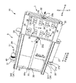
図1は、液体吐出装置の第1実施形態としてのカラーインクジェットプリンタ(以下、カラープリンタという)20の概要を示す斜視図である。
このカラープリンタ20は、カラー画像の出力が可能なインクジェットプリンタであり、例えば、シアン(C)、ライトシアン(淡いシアン、LC)、マゼンタ(M)、ライトマゼンタ(淡いマゼンタ、LM)、イエロ(Y)、ブラック(K)の6色の色インク等の液体を、印刷用紙等の様々な媒体上に吐出してドットを形成することによって印刷画像を印刷するインクジェット方式のプリンタである。尚、色インクは上記6色に限らず、例えばダークイエロ(暗いイエロ、DY)などを用いても良い。また、カラープリンタ20は、図1に示すように印刷用紙をロール状に巻き付けたロール紙や、JIS規格のA列0番用紙といった比較的大型の単票状の印刷用紙にも対応している。
このようなカラープリンタ20は、インクを吐出してロール紙Pに印刷する印刷部3と、ロール紙Pを搬送するための印刷用紙搬送部5とを有している。
【0025】
―――(1)印刷部―――
印刷部3は、複数の印刷ヘッド36を複数保持する移動体としてのキャリッジ28と、このキャリッジ28を、前記ロール紙Pの搬送方向(以下、副走査方向ともいう)とほぼ直交する方向(以下、主走査方向または左右方向ともいう)に往復移動可能に案内するための上下一対のガイドレール34と、同キャリッジ28を前記往復移動させるためのキャリッジモータ30と、このキャリッジモータ30の移動力をキャリッジ28に伝達するための牽引ベルト32とを備えている。
【0026】
(A)キャリッジ
キャリッジ28は略矩形状平板であり、その下端縁が上端縁よりも前方に突き出た傾斜状態で前記ガイドレール34に支持されている。このキャリッジ28の左端縁および右端縁のそれぞれにおける副走査方向の中央には、前記牽引ベルト32を固定するための係合部28a,28bが設けられている。そして、左の係合部28aからは、牽引ベルト32によって左方向の移動力Fが付与されてキャリッジ28は主走査方向の左側へ移動するとともに、逆に右の係合部28bからは右方向の移動力Fが付与されて右側へ移動する。
【0027】
尚、この移動力Fは主走査方向を向いており、よってこの移動力Fの作用線(移動力のはたらく点を通り、移動力の方向を向いた直線)は、前記左右の係合部28a,28bを結ぶ線分と一致するようになっている。そして、この作用線の近傍の部分は、前記移動力Fが直接伝達されるために、キャリッジ28移動中の振動が小さい部分となっている。このことは、後述する印刷ヘッド36のノズル列ユニット136の位置調整に関係する。
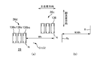
【0028】
このキャリッジ28には、その全面に亘って8つの印刷ヘッド36が配置されている。図2に印刷ヘッド36を拡大して示すが、印刷ヘッド36は、インクを吐出する多数のノズルnを有している。そして、これらノズルnは、副走査方向に沿って所定ピッチk・Dで列状に並べられることによってノズル列Nを構成している。このノズル列Nは、印刷ヘッド36一つ当たり6列設けられ、これらノズル列Nは、主走査方向に設計ピッチWnで並設されている。尚、この印刷ヘッド36及びノズルnの配列については後述する。
【0029】
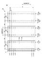
図3に、キャリッジ28上における印刷ヘッド36の平面配置図を示す。尚、この図は、キャリッジ28を背面側、すなわち後記プラテン26側から見ており、図1とは左右が反転している。同図に示すように、キャリッジ28平面の左右方向の中央を境として左側の領域には4つの印刷ヘッド36が、また右側の領域にも4つの印刷ヘッド36が配置され、各領域の印刷ヘッド36は、副走査方向に沿って設計ピッチ2L0(=2(H+k・D))で一直線に整列されている。つまり、各領域においては、副走査方向に隣り合う印刷ヘッド36,36同士は、互いの間に印刷ヘッド36一つ分に相当する間隔を隔てて配されている。尚、ここで、前記Hは、図2に示すように前記ノズル列Nの全長を示し、以下ではヘッド高さとも言う。
【0030】
一方、図3に示すように、左右に隣り合う印刷ヘッド36,36同士は、主走査方向には設計ピッチWhで配されているとともに、副走査方向については、互いに前記設計ピッチ2L0の半分だけシフトされており、よって印刷ヘッド36はキャリッジ28平面上の左右に千鳥状に配されている。詳細には、一方の片側の領域(例えば左側領域)における、印刷ヘッド36の存在しない間隔部分に対応させて、他方の片側の領域(例えば右側領域)の印刷ヘッド36が配置されており、もってそれぞれの領域における印刷ヘッド36が存在しない前記間隔部分を互いに補うようになっている。従って、キャリッジ28上の8つの印刷ヘッド36を合わせると、あたかも前記ノズル列Nの略8倍の全長のノズル列を有するのと同等となって、これによって大きな印刷画像の印刷を極短時間で実行可能となっている(図10を参照)。
【0031】
尚、これら8つの印刷ヘッド36の平面配置中心C2は、前記キャリッジ28の平面中心C1に一致させている。従って、前記牽引ベルト32の左右の係合部28a,28bを結ぶ線分は、前記印刷ヘッド36の平面配置を、副走査方向の上下に二分するようになっているとともに、前記係合部28a,28bに係る線分の中点は前記平面配置中心C2に一致している。つまり、前記係合部28a,28bを結ぶ線分は、図3においてキャリッジ28平面の左側領域の上から2番目の印刷ヘッド36と、右側領域の上から3番目の印刷ヘッド36との間に位置しており、この線分よりも上側の領域には、4つの印刷ヘッド36が、また下側の領域には、残る4つの印刷ヘッド36が配置されている。
【0032】
(B)ガイドレール
図1に示すように、ガイドレール34は、主走査方向に沿って2本が設けられている。そして、これらガイドレール34は、副走査方向に互いに間隔を隔てて上下に配置され、左右の両端部側にて基台となるフレーム(不図示)により支持されている。この2本のガイドレール34は、下側のガイドレール341が上側のガイドレール342より手前に配置されており、もって、これらに架け渡された前記キャリッジ28は、前述したように、その下端縁が前方に突き出た傾斜状態を維持しつつ主走査方向に往復移動するようになっている。
【0033】
(C)牽引ベルト
牽引ベルト32は金属製の帯状体であり、その一端がキャリッジ28の前記左の係合部28aに、またもう一端が、キャリッジ28の背面側を通って前記右の係合部28bに固定されている。また、この牽引ベルト32は、キャリッジ28の左右の移動ストローク端に設けられた一対のプーリ44a,44bに掛け回されている。そして、このうちの一方のプーリ44bには、前記キャリッジモータ30が連結されており、このキャリッジモータ30によって牽引ベルト32を介してキャリッジ28には主走査方向の移動力Fが付与されて、これによってキャリッジ28は同方向に移動する。
【0034】
―――(2)印刷用紙搬送部―――
印刷用紙搬送部5は、前記2本のガイドレール34の背面側に設けられている。そして、この印刷用紙搬送部5は、下側ガイドレール341より下方にてロール紙Pを回動自在に保持するロール紙保持部35と、上側のガイドレール342より上方にてロール紙Pを搬送するロール紙搬送部37と、それらロール紙保持部35とロール紙搬送部37との間にて搬送されるロール紙Pが沿わされるプラテン26とを有している。
【0035】
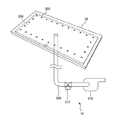
(A)プラテン
プラテン26は、搬送されるロール紙Pの全幅に亘る平面を有し、この平面が、前記傾斜状態にて走査するキャリッジ28の平面と平行になるように傾斜して設けられている。そして、このキャリッジ28に組み付けられる各印刷ヘッド36と等間隔を隔てて対向するようになっている。このプラテン26は、ロール紙Pを安定搬送させるための吸引機構16を備えているが、これについては後述する。
【0036】
(B)ロール紙保持部
ロール紙保持部35は、ロール紙Pを回転自在に保持するホルダ27を備えている。このホルダ27は、ロール紙Pを保持した状態で回動軸となる軸体27aを有し、その軸体27aの両端部には、供給するロール紙Pの蛇行や斜行を防止するためのガイド円盤27bがそれぞれ設けられている。
【0037】
(C)ロール紙搬送部
ロール紙搬送部37は、ロール紙Pを搬送するためのスマップローラ24と、これと対向して配置されスマップローラ24との間にロール紙Pを挟持する挟持ローラ29と、スマップローラ24を回動させるための搬送モータ31とを備えている。搬送モータ31の軸には駆動ギア40が、スマップローラ24の軸には駆動ギア40と噛み合う中継ギア41がそれぞれ設けられ、搬送モータ31の動力は、駆動ギア40と中継ギア41とを介してスマップローラ24に伝達される。すなわち、ホルダ27に保持されたロール紙Pは、スマップローラ24と挟持ローラ29との間に挟持され、搬送モータ31によって、ロール紙Pはプラテン26に沿って搬送される。
【0038】
(D)プラテンの吸引機構
図4は、プラテン26における吸引機構16を示す概念図である。このプラテン26には、ロール紙Pの搬送面側に多数の吸引孔302が、その周縁部に沿って環状に配設され、これら吸引孔302はプラテン26内部に設けられたチャンバ304と連通している。また、このチャンバ304は、プラテン26の背面側に設けられてチャンバ304内のエアーを吸引する吸引機構16と連通している。すなわち、吸引機構16は、多数の吸引孔302及びチャンバ304を介してプラテン26の外部と連通している。
【0039】
吸引機構16は、チャンバ304内のエアーを吸引してこれを負圧にする吸引ブロワ310と、吸引ブロワ310とチャンバ304とを接続するホース308と、ホース308に介設した切替バルブ312とを有している。切替バルブ312は、大気開放口を有する電磁三方弁で構成されている。そして、吸引ブロワ310を駆動すると、チャンバ304内の圧力が下がり、プラテン26に沿って搬送されるロール紙Pは、多数の吸引孔302を介して吸引され、ロール紙Pは撓むことなく、プラテン26に沿って平坦な状態にて搬送される。尚、前記切替バルブ312の切り替えによって、前記チャンバ304内を大気開放にすることもできる。
【0040】
===印刷ヘッドの構成===
―――(1)印刷ヘッドのノズル配列―――
図2に示すように、印刷ヘッド36は、多数のノズルnが副走査方向に沿って一直線上に整列されてなるノズル列Nを6列有しており、これらノズル列Nは、主走査方向に設計ピッチWnで並設されている。本実施形態においては、前記ノズル列Nとして、ブラックノズル列Nk、シアンノズル列Nc、ライトシアンノズル列Nlc、マゼンタノズル列Nm、ライトマゼンタノズル列Nlm、およびイエローノズル列Nyが、吐出するインク色毎に列をなしている。また、この印刷ヘッド36にあっては、前記ノズル列2列からなるノズル列群としての後記ノズル列ユニット136単位でキャリッジ28上における位置の調整を行えるようになっており、これについては後述する。
【0041】
各ノズル列Nは、それぞれに180個のノズルn1〜n180を有し、各々のノズルnには、ノズルnを駆動してインク滴を吐出させるための駆動素子としてピエゾ素子(不図示)が設けられている。ノズル列Nのノズルn1,n2,・・・n180は、副走査方向に沿って一定のノズルピッチk・Dで配置されている。ここで、Dは副走査方向のドットピッチであり、kは1以上の整数である。尚、副走査方向のドットピッチDは、主走査ライン(ラスタライン)のピッチとも等しくなっている。
【0042】
そして、印刷時には、ロール紙Pが印刷用紙搬送部5によって間欠的に所定の搬送量で搬送され、この間欠搬送における停留中にキャリッジ28が主走査方向に移動し、この移動中に各ノズルnからインク滴が吐出される。但し、印刷方式によっては、すべてのノズルnが常に使用されるとは限らず、一部のノズルnのみが使用される場合もある。
【0043】
―――(2)印刷ヘッドのノズル列ユニット―――
前述したように、印刷ヘッド36が備える6列のノズル列Nは、2列単位に区分されている。すなわち、印刷ヘッド36は、2列のノズル列Nからなるノズル列群としてのノズル列ユニット136を3ユニット備えている。図2にあっては、ブラックノズル列Nkとシアンノズル列Ncとが一つ目のノズル列ユニット136を構成し、以下、ライトシアンノズル列Nlcとマゼンダノズル列Nmとが二つ目136を、ライトマゼンダノズル列Nlmとイエローノズル列Nyとが三つ目のノズル列ユニット136をそれぞれ構成している。そして、このノズル列ユニット136単位で、キャリッジ28平面上における位置を調整可能となっている。尚、ここで言う位置の調整とは、主走査方向および副走査方向の位置の調整と、ノズル列Nの向きを副走査方向に揃えることを言う。
【0044】
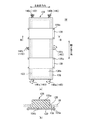
図5(a)に、図2の裏側から見たノズル列ユニット136を、また、図5(b)に、図5(a)中のB−B線矢視の断面図を示す。図2および図5に示すように、このノズル列ユニット136の外形形状は略直方体である。そして、その外壁面のうちの、キャリッジ28に組み付けられた際にプラテン26と対面する面136aには、ノズル列Nが2列設置されている(以下、設置面と言う)。この2列のノズル列Nは、予め高い精度で前記設計ピッチWnで平行に設置されており、この2列間の相対位置に関してはその後の調整が必要ないようになっている。
【0045】
また、図5に示すように、このノズル列Nの設置面136aと反対側の外壁面136bには、その四側縁に沿って延出した略矩形状の鍔状部138が一体に形成されている。この鍔状部138は、キャリッジ28に組み付けられたノズル列ユニット136を、キャリッジ28の平面に沿ってスライド移動可能に案内する案内部材である。すなわち、ノズル列ユニット136の組み付けは、キャリッジ28平面に形成された矩形開口部128に、ノズル列ユニット136が隙間をもって通されて、前記ノズル列Nの設置面136aがプラテン26に対面するようにしてなされるが、その際には、前記鍔状部138が矩形開口部128の四方の周囲部分に当接して係合するようになっている。尚、この鍔状部138を有する外壁面136bは、キャリッジ28平面にビス139a止めされた板材139によって面当たりされており、これによりキャリッジ28平面に押し付けられている。従って、ノズル列ユニット136は、前記キャリッジ28平面上において、当該平面からの離間は規制されつつ、所期の位置調整代分だけ主走査方向および副走査方向にスライド移動自在となっている。
【0046】
また、このノズル列ユニット136は、前記スライド移動量を調整するとともに、その調整後の位置にノズル列ユニット136を固定保持するための調整保持機構140,142備えている。この調整保持機構140,142は、前記主走査方向および副走査方向のそれぞれに対して設けられている。
【0047】
副走査方向の調整保持機構140は、前記鍔状部138の下端面に当接して設けられる左右一対の第1偏心カム140a,140aと、前記鍔状部138の上端面に当接して、前記第1偏心カム140aにノズル列ユニット136を押し付ける板バネ等の第1バネ部材140bとから構成される。一方、主走査方向の調整保持機構142は、前記鍔状部138の右側端面に当接して設けられる一つの第2偏心カム142aと、前記鍔状部138の左側端面に当接して前記第2偏心カム142aにノズル列ユニット136を押し付ける第2バネ部材142bとから構成される。
【0048】
そして、第1偏心カム140aを回転して副走査方向への押し出し量を調整することによって、ノズル列ユニット136の副走査方向の位置およびその副走査方向に対する傾きを調整する。すなわち、左右一対の第1偏心カム140a,140aの押し出し量を互いに同量だけ変更すれば、ノズル列ユニット136を副走査方向に並進移動させることができるとともに、互いの押し出し量を異ならせればその偏差分だけノズル列ユニット136の向きを傾けることができる。また、前記第2偏心カム142aを回転して主走査方向への押し出し量を調整することによって、ノズル列ユニット136を主走査方向に並進移動させてその主走査方向の位置を調整する。
【0049】
尚、前記第1および第2偏心カム140a,142aを回転させるためには、前記第1および第2バネ部材140b,142bの弾性力よりも大きな力を要する。従って、これら第1および第2偏心カム140a,142aは、ノズル列ユニット136を介して前記バネ部材140b,142bに押されているが、バネ部材140b,142bの弾性力によっては回転されないようになっている。
【0050】
===印刷ヘッドの駆動===
次に、印刷ヘッド36の駆動について図6を参照しつつ説明する。
図6は、ヘッド制御ユニット63(図8)内に設けられた駆動信号発生部の構成を示すブロック図であり、図7は、駆動信号発生部の動作を示す原信号ODRV、印刷信号PRT(i)、駆動信号DRV(i)のタイミングチャートである。
【0051】
図6において、駆動信号発生部200は、複数のマスク回路204と、原駆動信号発生部206と、駆動信号補正部230とを備えている。マスク回路204は、印刷ヘッド36のノズルn1〜n180をそれぞれ駆動するための複数のピエゾ素子に対応して設けられている。尚、図6において、各信号名の最後に付されたかっこ内の数字は、その信号が供給されるノズルの番号を示している。
【0052】
原駆動信号発生部206は、ノズルn1〜n180に共通に用いられる原駆動信号ODRVを生成する。この原駆動信号ODRVは、一画素分の主走査期間内に、第1パルスW1と第2パルスW2の2つのパルスを含む信号である。
駆動信号補正部230は、マスク回路204が整形した駆動信号波形のタイミングを復路全体で前後にずらし、補正を行う。この駆動信号波形のタイミングの補正によって、往路と復路におけるインク滴の着弾位置のズレが補正される、すなわち、往路と復路におけるドットの形成位置のズレが補正される。
【0053】
図6に示すように、入力されたシリアル印刷信号PRT(i)は、原駆動信号発生部206から出力される原駆動信号ODRVとともにマスク回路204に入力される。このシリアル印刷信号PRT(i)は、一画素当たり2ビットのシリアル信号であり、その各ビットは、第1パルスW1と第2パルスW2とにそれぞれ対応している。また、マスク回路204は、シリアル印刷信号PRT(i)のレベルに応じて原駆動信号ODRVをマスクするためのゲートである。すなわち、マスク回路204は、シリアル印刷信号PRT(i)が1レベルのときには原駆動信号ODRVの対応するパルスをそのまま通過させて駆動信号DRVとしてピエゾ素子に供給し、一方、シリアル印刷信号PRT(i)が0レベルのときには原駆動信号ODRVの対応するパルスを遮断する。
【0054】
図7に示すように、原信号ODRVは、各画素区間T1、T2、T3、T4において、第1パルスW1と第2パルスW2とを順に発生する。尚、画素区間とは、一画素分の主走査期間と同じ意味である。そして、図示のように印刷信号PRT(i)が2ビットの画素データ『1、0』に対応しているときは、第1パルスW1のみが一画素区間の前半で出力される。これにより、ノズルから小さいインク滴が吐出され、印刷用紙には小さいドット(小ドット)が形成される。また、印刷信号PRT(i)が2ビットの画素データ『0、1』に対応しているときには、第2パルスW2のみが一画素区間の後半で出力される。そして、これにより、ノズルから中サイズのインク滴が吐出され、印刷用紙には中サイズのドット(中ドット)が形成される。また、印刷信号PRT(i)が2ビットの画素データ『1、1』に対応しているときには、第1パルスW1と第2パルスW2とが一画素区間で出力される。そして、これにより、ノズルから大きいインク滴が吐出され、印刷用紙には大きいドット(大ドット)が形成される。また、印刷信号PRT(i)が2ビットの画素データ『0、0』に対応しているときには、第1パルスW1および第2パルスW2のいずれも一画素区間で出力されない。そして、この場合には、ノズルからインク滴が吐出されず、印刷用紙にはドットが形成されない。
【0055】
以上説明したとおり、一画素区間における駆動信号DRV(i)は、印刷信号PRT(i)の4つの異なる値に応じて互いに異なる4種類の波形を有するように整形され、これらの信号に基づいて印刷ヘッド36は、3種類のサイズのドットを形成するか、若しくはドットを形成しないようにすることができるようになっている。
【0056】
===液体吐出装置の制御構成例===
次に液体吐出装置としてのカラープリンタ20の制御構成例について、図8及び図9を用いて説明する。図8は、カラープリンタ20の制御構成を示すブロック図である。図9は、画像処理ユニット38の構成を示すブロック図である。
【0057】
このカラープリンタ20は、パーソナルコンピュータ等のコンピュータ90に接続して使用され、このコンピュータ90から送信された画像データに基づいてロール紙Pに印刷画像を印刷する。尚、このカラープリンタ20に前記コンピュータ90を加えた上記構成を、広義の「液体吐出装置」と呼ぶこともできる。
【0058】
このコンピュータ90は、CRT21及び、図示しない、液晶表示装置等の表示装置、キーボードやマウス等の入力装置、フレキシブルドライブ装置、CD−ROMドライブ装置等のドライブ装置等を備えている。そして、このコンピュータ90では、所定のオペレーティングシステムの下で、アプリケーションプログラム95が動作している。オペレーティングシステムには、ビデオドライバ91が組み込まれており、画像のレタッチなどを行うアプリケーションプログラム95は、処理対象の画像に対して所望の処理を行い、また、ビデオドライバ91を介してCRT21に画像を表示する。
【0059】
カラープリンタ20は、アプリケーションプログラム95からの画像データ等が入力される情報生成手段としての画像処理ユニット38と、カラープリンタ20全体の動作を制御するシステムコントローラ54と、メインメモリ56と、EEPROM58とを備えている。システムコントローラ54には、さらに、キャリッジモータ30を駆動する主走査駆動回路61と、搬送モータ31を駆動するための副走査駆動回路62と、各印刷ヘッド36に対応させて設けられ、これら印刷ヘッド36を制御するための制御手段としての8つのヘッド制御ユニット63と、が接続されている。
【0060】
そして、アプリケーションプログラム95が印刷命令を発すると、カラープリンタ20に設けられた画像処理ユニット38が、画像データをアプリケーションプログラム95から受け取り、これを印刷データPDに変換する。図9に示すように、この画像処理ユニット38の内部には、解像度変換モジュール97と、色変換モジュール98と、ハーフトーンモジュール99と、ラスタライザ100と、UIプリンタインターフェースモジュール102と、ラスタデータ格納部103と、色変換ルックアップテーブルLUTと、バッファメモリ50と、イメージバッファ52が備えられている。
【0061】
解像度変換モジュール97は、アプリケーションプログラム95で形成されたカラー画像データの解像度を、画像データと共に受け取った印刷モード等の情報に基づいて、対応する印刷解像度に変換する役割を果たす。こうして解像度変換された画像データは、まだRGBの3つの色成分からなる画像情報である。色変換モジュール98は、色変換ルックアップテーブルLUTを参照しつつ、画素毎にRGB画像データを、カラープリンタ20が利用可能な複数のインク色の多階調データに変換する。
【0062】
色変換された多階調データは、例えば256階調の階調値を有している。ハーフトーンモジュール99は、いわゆるハーフトーン処理を実行してハーフトーン画像データを生成する。ここでハーフトーンは、例えば画像を、画素を形成可能な複数の部位にて構成される所定領域毎に分割し、各領域における濃度を、その領域を構成する複数の部位に、大ドット、中ドット、小ドットのいずれかを形成するか否かにより各領域の濃度を表現するものとする。このため、ハーフトーン画像データは、各画素のデータが、画素毎の階調を示す2値データとして生成される。
【0063】
このハーフトーン画像データは、ラスタライザ100により所望のデータ順に並べ替えられ、最終的な印刷データPDとしてラスタデータ格納部103に対して出力される。この印刷データPDは、各主走査時のドットの形成状態を示すラスターデータと、副走査送り量を示すデータとを含んでいる。
【0064】
一方、コンピュータ90に備えられたユーザインターフェース表示モジュール101は、印刷に関係する種々のユーザインターフェースウィンドウを表示する機能と、それらのウィンドウ内におけるユーザの入力を受け取る機能とを有している。例えば、ユーザは、印刷用紙の種類、サイズや印刷モード等をユーザインターフェース表示モジュール101に指示することが可能である。
【0065】
また、UIプリンタインターフェースモジュール102は、ユーザインターフェース表示モジュール101とカラープリンタ20との間のインターフェースとしての機能を有している。ユーザがユーザインターフェースにより指示した命令を解釈して、システムコントローラ54等へ各種コマンドCOMを送信したり、逆に、システムコントローラ54等から受信したコマンドCOMを解釈して、ユーザインターフェースへ各種表示を行ったりする。例えば、ユーザインターフェース表示モジュール101により受け取られた印刷用紙の種類、サイズ等に係る前記指示は、UIプリンタインターフェースモジュール102へ送られ、UIプリンタインターフェースモジュール102は、指示された命令を解釈してシステムコントローラ54へコマンドCOMを送信する。
【0066】
また、UIプリンタインタフェースモジュール102は、印刷モード設定部としての機能も有する。すなわち、UIプリンタインタフェースモジュール102は、ユーザインターフェース表示モジュール101により受け取られた印刷情報、すなわち印刷する画像の解像度、印刷に使用するノズルに係る情報、副走査送り量を示すデータに係る情報等に基づいて記録モードとしての印刷モードを決定し、この印刷モードに応じた印刷データPDがハーフトーンモジュール99やラスタライザ100により生成され、ラスタデータ格納部103へ出力する。
【0067】
ラスタデータ格納部103に出力された印刷データPDは、一旦、バッファメモリ50に蓄えられ、ノズルに対応したデータに変換されてイメージバッファ52に格納される。カラープリンタ20のシステムコントローラ54は、UIプリンタインターフェースモジュール102により出力されたコマンドCOMの情報に基づいて主走査駆動回路61、副走査駆動回路62、ヘッド制御ユニット63等を制御し、イメージバッファ52のデータに基づいて印刷ヘッド36に設けられた各色のノズルを駆動して印刷する。ここで、印刷モードとしては、例えば、いわゆるインターレース方式を用いてドットを記録する高画質モード、当該方式を用いないでドットを記録する高速モードなどがある。
【0068】
===液体吐出装置の動作===
図10に、上述した液体吐出装置としてのカラープリンタ20の印刷動作を説明するための説明図を示す。ここでは、前記印刷動作の一例として、キャリッジ28の8つの印刷ヘッド36を用いて、ロール紙Pに一つの印刷画像「A」を印刷する場合を例に説明する。尚、この印刷画像「A」の副走査方向の大きさは、同図に示すように、印刷ヘッド36のヘッド高さHの略8倍であるものとし、前記8つの印刷ヘッド36を、あたかも一つの印刷ヘッドの如く使用して、キャリッジ28の一回の走査によって前記印刷画像「A」12を印刷する。
すなわち、この印刷画像「A」12は、副走査方向に関して8つの帯状画像12a,12b,…12hに区分され、各帯状画像は、副走査方向の上下に隣接する帯状画像との間に隙間や重複部分が無い連続状態に印刷される。そして、各帯状画像の印刷は、帯状画像毎に対応する各印刷ヘッド36によってなされる。詳細には、副走査方向の一番上の印刷ヘッド36aを用いて、副走査方向の一番上の帯状画像12aを印刷し、上から2番目の印刷ヘッド36bを用いて上から2番目の帯状画像12bを印刷し、以降3番目から8番目についても各番目の印刷ヘッド36c,36d,…36hを用いて、その対応する番号の帯状画像12c,12d,…12hを印刷するように指示する。
【0069】
ユーザインターフェース表示モジュール101により受け取られたこれらの指示は、前述した8つの画像処理ユニット38a,38b,…38hに備えられたUIプリンタインターフェースモジュール102へ送られ、UIプリンタインターフェースモジュール102は、指示された命令を解釈してシステムコントローラ54へコマンドCOMを送信する。
【0070】
次に、ユーザはアプリケーションプログラム95等において印刷を行う旨を指示する。本指示を受け取ったアプリケーションプログラム95が、印刷命令を発すると、前述した8つの画像処理ユニット38a,38b,…38hが、それぞれに前記印刷画像「A」12における8等分された帯状画像12a,12b,…12hに対応する各画像データをアプリケーションプログラム95からそれぞれ受け取り、これらを印刷データPDに変換した後にバッファメモリ50に送信する。各々の画像処理ユニット38a,38b,…38hは、それぞれ各印刷ヘッド36a,36b,…36hに対応した印刷データPDを、バッファメモリ50により受信した後に、イメージバッファ52へ送信する。
【0071】
また、各々の画像処理ユニット38a,38b,…38hは、上述したコマンドCOMをシステムコントローラ54へ送信する。システムコントローラ54は、各々の画像処理ユニット38a,38b,…38hから受け取った情報に基づいて、主走査駆動回路61、副走査駆動回路62、及び、前述した8つのヘッド制御ユニット63a,63b,…63hに対して制御信号を送る。
【0072】
また、各々のヘッド制御ユニット63a,63b,…63hは、システムコントローラ54からの制御信号に従って、それぞれのヘッド制御ユニット63に対応した画像処理ユニット38a,38b,…38h内のイメージバッファ52から各色成分の印刷データを読み出す。そして、各々のヘッド制御ユニット63a,63b,…63hは、当該読み出されたデータに基づいて、対応する印刷ヘッド36a,36b,…36hを制御する。
【0073】
そして、前記主走査駆動回路61によりキャリッジモータ30を制御してキャリッジ28を主走査方向に移動させて、各々の印刷ヘッド制御ユニット63a,63b,…63hにより制御された各印刷ヘッド36a,36b,…36hからインクを吐出して、ロール紙Pに印刷を行って印刷画像「A」12を印刷する。
【0074】
但し、この印刷画像12に係る各帯状画像12a,12b,…12hは、前記複数のノズル列Nからインク滴を吐出して形成された多数のドット列から構成される。このため、これらドット列の形成位置が、所期の設計位置からずれている場合には、ロール紙P上に綺麗な印刷画像を描けない。
【0075】
このドット列の形成位置が設計位置からずれる要因としては、ノズル列Nの主走査方向および副走査方向に対する位置精度が挙げられる。特に、本実施形態にあっては、8つの印刷ヘッド36を備えているため、前記キャリッジ28上における8つの印刷ヘッド36に亘って、そのノズル列Nの向き、主走査方向の相対位置、および副走査方向の相対位置の整合が取れていないと、前記帯状画像12a,12b,…12h同士の印刷位置の整合がとれず、もって、8つの帯状画像が一つになって形成される前記印刷画像「A」は、綺麗に印刷されない。例えば、8つの印刷ヘッド36に亘ってノズル列N向きが副走査方向に平行に揃っていないと、ノズル列Nにて形成されるドット列の向きが帯状画像同士で異なってしまい、もって帯状画像の境界部分等で画像が不連続になってしまう。また、各印刷ヘッド36のノズル列Nの主走査方向の相対位置が、図3に示す設計位置になっていないと、印刷ヘッド36毎にドット列の形成位置が主走査方向にずれてしまい、もって帯状画像同士の境界部分等で画像が不連続になってしまう。更には、副走査方向の相対位置が、図3に示す設計位置になっていないと、印刷ヘッド36毎にドット列の形成位置が副走査方向にずれてしまい、もって帯状画像同士の境界部分等で、空白といった未印刷部分や画像の重なり部分を生じて画像が不連続となる。
【0076】
従って、本発明にあっては、前記ノズル列ユニット136の調整保持機構140,142を用いて、ノズル列ユニット136毎に以下に示す位置調整を行い、これによって印刷ヘッド36の相対位置等の整合を取るようにしている。
【0077】
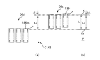
===印刷ヘッドのノズル列ユニットの位置調整===
図3を参照しながら、ノズル列ユニット136の位置調整方法の基本的な考え方を説明する。尚、ノズル列ユニット136の位置調整とは、キャリッジ28上における主走査方向および副走査方向の位置の調整と、その向きを副走査方向に揃える調整とを言う。詳細には、所定の一つのノズル列ユニット136sを基準として、この基準ノズル列ユニット136sに対して、調整対象のノズル列ユニット136の位置が、図3に示す設計位置となるように調整することを言う。例えば、基準ノズル列ユニット136sからの主走査方向および副走査方向の相対位置を、設計ピッチWh,L0だけ離して配置するとともに、そのノズル列ユニット136の向きを基準ノズル列ユニット136sと平行に揃える。
【0078】
ここで、本発明にあっては、この位置調整の基準となるノズル列ユニット136sとしては、キャリッジ28の移動力である牽引ベルト32の牽引力Fの作用線に最も近い側のノズル列ユニット136sを用いるようにしている。すなわち、図3の例にあっては、印刷ヘッド36dまたは印刷ヘッド36eが備えるノズル列ユニット136sのうちのいずれか一つのノズル列ユニットを基準にする。
【0079】
この理由は、キャリッジ28における前記作用線に近い部分は、前記牽引力Fがより直接伝達されるために、キャリッジ28移動中の振動が小さく、よって、前記作用線に近いノズル列ユニット136sほど、前記移動中にロール紙Pに向けて吐出されたインク滴の、振動による着弾位置ズレたるドット形成位置ズレが小さいためである。そして、このドット形成位置ズレの小さいノズル列ユニット136sを基準にして他のノズル列ユニット136の位置を調整すれば、ノズル列ユニット136,136間のドット列の形成位置の整合を正確に取ることが可能となる。
【0080】
尚、図示例のように、この作用線に最も近いノズル列ユニット136sが、6ユニットというように複数ある場合には、そのうちの、前記一対の牽引力Fの作用点である前記一対の係合部28a,28bの間の中点に最も近いノズル列ユニット136bsを基準にする。
【0081】
これの理由は、前記往復移動中のキャリッジ28においては、その振動が平均的に最も小さい部分は、前記一対の作用点28a,28bの間の中点であるからである。本実施例の場合には、この中点は、キャリッジ28の平面中心C1に相当するため、この平面中心C1に最も近いノズル列ユニット136bsを基準として他のノズル列ユニット136の位置を調整していく。尚、図示例にあっては、上記条件に該当するノズル列ユニット136bsが、印刷ヘッド36d,36eのそれぞれについて一つずつ存在するが、これらについてはいずれのノズル列ユニット136bsを基準にしても良く、以下では、印刷ヘッド36dのノズル列ユニット136bsを基準に選択したものとして説明する。
【0082】
以下、図11〜図18を参照しつつ、ノズル列ユニット136の位置の調整方法を具体的に説明する。尚、これら図11〜図18のいずれも、その(a)図には、キャリッジ28上におけるノズル列ユニットの平面配置を示し、また(b)図には、このノズル列ユニットからインク滴を吐出してロール紙Pに描かれたドット列または横罫線を示している。
【0083】
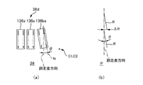
―――(1)基準ノズル列ユニットの位置調整―――
始めに、基準ノズル列ユニット136bsの向きを副走査方向に平行に揃える調整をする。この調整手順は、先ず、図11(a)に示すように、基準ノズル列ユニット136bsが備える2列のうちの一方のノズル列Nからロール紙Pに向けてインク滴を吐出して、図11(b)に示すようにドット列R(図中上側のドット列)を一列形成する。尚、前記ドット列Rを形成するノズル列Nとしては、前記2列のうちの前記中点に近い列を選択すると更に良い。
しかる後、副走査方向に略ヘッド高さH分だけ紙送りして、再度同じノズル列Nからインク滴を吐出してドット列R(図中下側のドット列)を形成する。
【0084】
ここで、図11(a)に示すように、基準ノズル列ユニット136bsのノズル列Nの向きが副走査方向に平行に揃っている場合には、図11(b)に示すように前記二つのドット列Rは一直線上に乗る。しかし、図12(a)のように傾いている場合には、その傾きが、図12(b)に示すように、二つのドット列R間の位置ズレ量ΔRとなって顕れる。つまり、副走査方向に対する傾き角θは、一方のドット列Rの下端と、他方のドット列Rの上端との間の、主走査方向の位置ズレ量ΔRとして示される。そして、この位置ズレ量ΔRが、基準ノズル列ユニット136bsの傾きの調整代である。従って、図5に示した前記一対の第1偏心カム140,140aを、前記位置ズレ量ΔRだけ互いの間に差をつけて回転して、基準ノズル列ユニット136bsの向きを副走査方向に揃える。
【0085】
―――(2)他のノズル列ユニットの位置調整―――
このようにして、基準ノズル列ユニット136bsの向きを副走査方向に揃えたら、これを基準にして、他のノズル列ユニット136の位置を調整する。当該他のノズル列ユニット136の位置調整は、基準ノズル列ユニット136bsに対する傾きの調整、基準ノズル列ユニット136sに対する主走査方向の相対位置の調整、基準ノズル列ユニット136sに対する副走査方向の相対位置の調整の三つに大別される。ここでは、図3に示す基準ノズル列ユニット136bsの斜め上に位置する印刷ヘッド36cのノズル列ユニット136(図中、右端のノズル列ユニット)を調整する場合を例に説明する。
【0086】
(A)ノズル列ユニットの傾きの調整
始めに、調整対象のノズル列ユニット136の向きが、基準ノズル列ユニット136bsと平行になるように調整する。具体的には、先ず、図13(a)に示すように、基準ノズル列ユニット136sの一方のノズル列Nからロール紙Pに向けてインク滴を吐出して図13(b)に示す基準ドット列Rsを一列形成する。しかる後、キャリッジ28移動および紙送りを適宜行って、副走査方向における前記基準ドット列Rsの隣に、調整対象のノズル列ユニット136の一方のノズル列Nからインク滴を吐出してドット列Rを形成する。
【0087】
ここで、図13(a)のように、このノズル列ユニット136の向きが基準ノズル列ユニット136sと平行に揃っている場合には、図13(b)に示すように、これら二つのドット列Rs,Rは平行になる。すなわち、二つのドット列Rs,Rの上端の間隔ΔRuと、下端の間隔ΔRdとは等しくなる。しかし、図14(a)に示すように傾いている場合には、その傾き角θが、図14(b)に示すように二つのドット列Rs,Rの上端の間隔ΔRuと下端の間隔ΔRdとの偏差(=ΔRu−ΔRd)となって顕れる。そして、この偏差(=ΔRu−ΔRd)が、前記調整対象のノズル列ユニット136の傾きの調整代である。従って、図5に示した前記一対の第1偏心カム140,140aを、前記偏差分だけ互いの間に差をつけて回転して、ノズル列ユニット136の向きを揃える。
【0088】
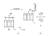
(B)ノズル列ユニットの副走査方向の相対位置の調整
次に、ノズル列ユニット136の副走査方向の相対位置が設計位置になるように調整する。すなわち、図15(a)に示すように、調整対象のノズル列ユニット136を、前記基準ノズル列ユニット136bsから設計ピッチL0だけ副走査方向に離れた位置に設定する。
具体的には、先ず、図15(a)に示すように、基準ノズル列ユニット136bsおよび調整対象のノズル列ユニット136のノズル列Nのそれぞれの上端のノズルnからロール紙Pに向けてインク滴を吐出しながら主走査方向にキャリッジ28を移動させて、これにより図15(b)に示すように主走査方向の罫線Ks,K(以下では横罫線と言う)を一対描く。尚、横罫線Ksは、基準ノズル列ユニット136bsのノズルnによって、また横罫線Kは、調整用のノズル列ユニット136のノズルnによって描かれたものである。
【0089】
ここで、図15(a)に示すように、基準ノズル列ユニット136bsに対して調整対象のノズル列ユニット136が、副走査方向に上記設計ピッチL0どおり離れて位置していれば、両横罫線Ks,Kの間隔Lは、前記設計ピッチL0に等しくなる。しかし、図16(a)に示すように、調整対象のノズル列ユニット136の相対位置が、前記設計位置からずれていれば、この位置ズレは、両横罫線Ks,Kの間隔Lと前記設計ピッチL0との偏差ΔL(=L−L0)となって顕れる。そして、この偏差ΔLが、前記調整対象のノズル列ユニット136の副走査方向の位置の調整代であり、この偏差ΔL分だけ、図5に示した前記一対の第1偏心カム140,140aを回転して、その副走査方向における相対位置を調整する。
【0090】
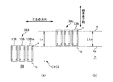
(C)ノズル列ユニットの主走査方向の相対位置の調整
次に、ノズル列ユニット136の主走査方向の相対位置が設計位置になるように調整する。すなわち、図17(a)に示すように、調整対象のノズル列ユニット136を、前記基準ノズル列136bsから設計ピッチWhだけ主走査方向に離れた位置に設定する。
具体的には、先ず、図17(a)に示すように、基準ノズル列ユニット136bsおよび調整対象のノズル列ユニット136のそれぞれのノズル列Nからロール紙Pに向けてインク滴を吐出して、図17(b)に示すように基準ドット列Rsおよび調整対象のドット列Rを形成する。ここで、図17(a)に示すように、基準ノズル列ユニット136bsに対して調整対象のノズル列ユニット136が、主走査方向に上記設計ピッチWhどおり離れて位置していれば、図17(b)に示す両ドット列Rs,Rの間隔Wは、前記設計ピッチWhに等しくなる。しかし、図18(a)に示すように、調整対象のノズル列ユニット136の相対位置が前記設計位置からずれていれば、この位置ズレは、図18(b)に示すように両ドット列Rs,Rdの間隔Wと前記設計ピッチWhとの偏差ΔW(=W−Wh)となって顕れる。そして、この偏差ΔWが、前記調整対象のノズル列ユニット136の主走査方向の位置の調整代であり、この偏差ΔW分だけ、図5に示した前記第2偏心カム142aを回転して、その副走査方向における相対位置を調整する。
【0091】
尚、前記位置調整用のドット列R,Rsおよび横罫線K,Ksは、多数のドットから構成されるが、このドットのサイズは、実使用により近い状態、すなわち実使用頻度の高い大きさにするのが好ましい。これは、ドットのサイズによってインク滴量が変化するが、このインク滴量に応じて吐出速度等の変化を来たしその着弾位置たるドット形成位置が微妙に変わる場合があるためである。例えば、本実施例のドットのサイズは、前述したように大中小の三段階であるが、大ドットよりも実使用頻度の高い中ドットや小ドットを用いるのが好ましい。また、実使用時の印刷画像において、ドット列の形成位置ズレが目立ち易いのは、印刷画像におけるハイライト部分であり、このハイライト部分では小ドットの使用頻度が高い。従って、更に好ましくは、小ドットを用いてドット列R,Rsおよび横罫線K,Ksを形成すると良い。
【0092】
以上、他のノズル列ユニット136の位置調整手順について、印刷ヘッド36cのノズル列ユニット136を調整する場合を例に説明してきたが、この例説したノズル列ユニット136以外の他の印刷ヘッド36a,36b,36e,36f,36g,36hに係るノズル列ユニット136に対して、更には基準ノズル列ユニット136bsと同じ印刷ヘッド36d内にあるノズル列ユニット136sに対しても、同様の手順で位置調整できるのは言うまでもない。すなわち、これら他の印刷ヘッド等のノズル列ユニット136に関しては、基準ノズル列ユニット136bsとの副走査方向の設計ピッチWhが、Wh−2Wn,Wh−4Wn,0,2Wn,4Wnに変わり、また主走査方向の設定ピッチL0が、2L0,3L0,4L0に変わるだけである。よって、その説明は省略する。
【0093】
===その他の実施の形態===
以上、一実施形態に基づき本発明に係る液体吐出装置等を説明してきたが、上記した発明の実施の形態は、本発明の理解を容易にするためのものであり、本発明を限定するものではない。本発明は、その趣旨を逸脱することなく、変更、改良され得ると共に、本発明にはその等価物が含まれることは勿論である。
【0094】
例えば、以下に述べる実施形態も、本発明に係る液体吐出装置に含まれる。すなわち、カラーフィルタ製造装置、染色装置、微細加工装置、半導体製造装置、表面加工装置、三次元造形機、液体気化装置、有機EL製造装置(特に高分子EL製造装置)、ディスプレイ製造装置、成膜装置、DNAチップ製造装置などに、本実施形態と同様の技術を適用しても良い。また、これらの方法や製造方法も応用範囲の範疇である。
【0095】
前述の実施形態では、染料インク又は顔料インクといったインクをノズルnから吐出していた。しかし、ノズルnから吐出する液体は、このようなインクに限られるものではない。例えば、金属材料、有機材料(特に高分子材料)、磁性材料、導電性材料、配線材料、成膜材料、電子インク、加工液、遺伝子溶液などを含む液体(水も含む)をノズルから吐出しても良い。このような液体を対象物に向かって直接的に吐出すれば、省材料、省工程、コストダウンを図ることができる。
【0096】
前述の実施形態では、キャリッジ28の副走査方向の中央に、主走査方向の移動力Fを受けるための一対の係合部28a,28bを設けたが、この係合部28a,28bの位置はこれに限るものではなく、例えば、図19に示すように副走査方向の端部に設けるようにしても良い。尚、図19(a)は、前記係合部28a,28bをキャリッジ28の上端部に、また、図19(b)は、下端部に設けたものである。そして、いずれの場合も、前記位置調整の基準となる基準ノズル列ユニット136bsは、前記係合部28a,28bの中点C3に最も近いノズル列ユニット136bsとなるのは言うまでもない。
【0097】
前述の実施形態では、キャリッジ28上の位置を調整可能な最小単位であるノズル列群として、二列のノズル列Nを備えたノズル列ユニット136を例示したが、このノズル列ユニット136が備えるノズル列Nの数は、これに限るものではない。例えば、このノズル列ユニット136にノズル列Nを一列だけ設けて、一列単位で位置調整可能にしても良いし、更には図2に示す、ブラックノズル列Nkからイエローノズル列Nyまでの六列のノズル列Nをノズル列ユニット136に設けて、六列単位で位置調整可能にしても良い。尚、この六列のノズル列を有するノズル列ユニット136は、実質的に前記印刷ヘッド36と同等となるのは言うまでもない。
【0098】
前述の実施形態では、ピエゾ素子を用いてインクを吐出していた。しかし、液体を吐出する方式は、これに限られるものではない。例えば、熱によりノズル内に泡を発生させる方式など、他の方式を用いてもよい。
【0099】
前述の実施形態では、印刷用紙としてロール紙Pを例にとって説明したが、印刷用紙にA列0番用紙等を用いてもよい。
【0100】
前述の実施形態では、独立に位置調整可能な最小単位であるノズル列群として例示したノズル列ユニット136は、副走査方向に間隔を隔てて配されていたが、これに限るものではない。例えば、副走査方向に間隔を隔てずにノズル列ユニット136を連続配置し、見かけ上8つのノズル列ユニット136が副走査方向に一直線に繋がっているようにしても良い。尚、この場合には、副走査方向に8つのノズル列が連なっており、一見すると、副走査方向に亘って一列のノズル列に見えるが、実質的には8つのノズル列ユニット136毎に分かれているため、それぞれ独立に位置調整が可能である。従って、この一見一体に見えるノズル列に対しても、これを構成する8つのノズル列のうちで前記作用線に最も近いノズル列を基準として他のノズル列の位置調整すれば良い。
【0101】
【発明の効果】
本発明によれば、媒体に向けて吐出された液体の着弾位置に関し、ノズル列同士の間の整合を正確に取ることが可能な液体吐出装置、およびそのノズル列の位置の調整方法を実現することが可能となる。
【図面の簡単な説明】
【図1】本発明にかかるカラープリンタの第1実施形態の概要を示す斜視図である。
【図2】印刷ヘッドを拡大して示す図である。
【図3】キャリッジ上における印刷ヘッドの平面配置図である。
【図4】プラテンにおける吸引機構を表す概念図である。
【図5】ノズル列ユニットの説明図であって、図5(a)は、図2の裏側から見たノズル列ユニットを示す図であり、図5(b)は、図5(a)中のB−B線矢視の断面図である。
【図6】ヘッド制御ユニット内に設けられた駆動信号発生部の構成を示す図である。
【図7】駆動信号発生部の動作を示すタイミングチャートである。
【図8】カラープリンタを備えた印刷システムの構成を示すブロック図である。
【図9】画像処理ユニットの構成を示すブロック図である。
【図10】カラープリンタの印刷動作を説明するための説明図である。
【図11】ノズル列ユニットの位置の調整方法を説明するための説明図である。
【図12】ノズル列ユニットの位置の調整方法を説明するための説明図である。
【図13】ノズル列ユニットの位置の調整方法を説明するための説明図である。
【図14】ノズル列ユニットの位置の調整方法を説明するための説明図である。
【図15】ノズル列ユニットの位置の調整方法を説明するための説明図である。
【図16】ノズル列ユニットの位置の調整方法を説明するための説明図である。
【図17】ノズル列ユニットの位置の調整方法を説明するための説明図である。
【図18】ノズル列ユニットの位置の調整方法を説明するための説明図である。
【図19】本発明に係る他の実施形態を説明するための説明図である。
【符号の説明】
3 印刷部 5 印刷用紙搬送部
12 印刷画像 12a〜12h 帯状画像
16 吸引機構 20 カラープリンタ
21 CRT 24 スマップローラ
26 プラテン 27 ホルダ
27a 軸体 27b ガイド円盤
28 キャリッジ 28a,28b 係合部
128 キャリッジの矩形開口部 136 ノズル列ユニット
136a 外壁面(設置面) 136b 外壁面
136s ノズル列ユニット 136bs 基準ノズル列ユニット
138 鍔状部 139 板材
139a ビス 140 副走査方向の調整保持機構
140a 第1偏心カム 140b 第1バネ部材
142 主走査方向の調整保持機構 142a 第2偏心カム
142b 第2バネ部材 29 挟持ローラ
30 キャリッジモータ 31 搬送モータ
32 牽引ベルト 34 ガイドレール
341 下側ガイドレール 342 上側ガイドレール
35 ロール紙保持部 36,36a〜36h 印刷ヘッド
37 ロール紙搬送部 38,38a〜38h 画像処理ユニット
40 駆動ギア 41 中継ギア
44a,44b プーリ 50 バッファメモリ
52 イメージバッファ 54 システムコントローラ
56 メインメモリ 58 EEPROM
61 主走査駆動回路 62 副走査駆動回路
63,63a〜63h ヘッド制御ユニット
90 コンピュータ 91 ビデオドライバ
95 アプリケーションプログラム 97 解像度変換モジュール
98 色変換モジュール 99 ハーフトーンモジュール
100 ラスタライザ
101 ユーザインターフェース表示モジュール
102 UIプリンタインターフェースモジュール
103 ラスタデータ格納部 200 駆動信号発生部
204 マスク回路 206 原駆動信号発生部
230 駆動信号補正部 302 吸引孔
304 チャンバ 308 ホース
310 吸引ブロア 312 切替バルブ
C1 キャリッジの平面中心 C2 印刷ヘッドの平面配置中心
COM コマンド F 移動力、牽引力
LUT 色変換ルックアップテーブル
n,n1〜n180 ノズル
N,Nk,Nc,Nlc,Nm,Nlm,Ny ノズル列
P ロール紙 PD 印刷データ[0001]
TECHNICAL FIELD OF THE INVENTION
The present invention includes a moving body that moves by receiving a moving force, and a plurality of nozzle rows that discharge liquid toward a medium, and a liquid ejection apparatus that can adjust the position of the nozzle row on the moving body, and a The present invention relates to a method for adjusting the position of a nozzle row.
[0002]
[Prior art]
2. Description of the Related Art Among liquid ejecting apparatuses that eject a liquid from a nozzle row (a number of nozzles arranged in a straight line) toward a medium, an ink jet printer that ejects ink as the liquid has recently become widespread. The ink jet printer includes a print head including a plurality of the nozzle rows, and a carriage that reciprocates in the main scanning direction while holding the print head. Then, the printing paper as the medium is intermittently fed in a sub-scanning direction orthogonal to the main scanning direction, and the carriage is moved in the main scanning direction while the paper feeding is stopped, and is directed toward the printing paper. Ink droplets are ejected from the nozzle array to form a large number of dot arrays (a large number of dots, which are ink droplet landing marks, are aligned in a straight line) on printing paper. Then, such a paper feed and the movement of the carriage are alternately repeated to form a predetermined print image on the print paper. Recently, the types of such ink jet printers have been increased, and for example, a large ink jet printer capable of performing large-format printing such as row A No. 0 by arranging a plurality of print heads on the carriage has been provided.
[0003]
A print image formed by such an inkjet printer is composed of a large number of dot rows formed by discharging ink droplets from nozzle rows. For this reason, when the dot row formation position, which is the landing position of the ink droplet on the printing paper, is deviated from the intended design position, a beautiful print image cannot be drawn on the printing paper. In particular, in the case of a large-sized inkjet printer having a plurality of print heads as described above, if the positions of the nozzle rows are not aligned between the plurality of print heads on the carriage, the formation of dot rows between the print heads may occur. Position alignment is lacking, and if one print image is drawn using all these print heads, a beautiful print image cannot be drawn.
[0004]
Therefore, with respect to such a large-sized printer, a printer capable of adjusting the position of the print head on the carriage for each print head has been proposed (for example, see Patent Document 1). According to this configuration, the positions of the nozzle rows on the carriage are aligned by appropriately moving each print head in the main scanning direction and the sub-scanning direction.
[0005]
[Patent Document 1]
JP-A-9-262992
[0006]
[Problems to be solved by the invention]
However,
[0007]
The present invention has been made in view of such a problem, and an object of the present invention is to enable accurate alignment between nozzle rows with respect to a landing position of a liquid ejected toward a medium. It is an object of the present invention to realize a liquid ejecting apparatus and a method for adjusting a position of a nozzle array.
[0008]
[Means for Solving the Problems]
A main aspect of the present invention is a liquid ejecting apparatus including a moving body that moves by receiving a moving force, and a plurality of nozzle rows that eject liquid toward a medium, and in which the position of the nozzle row on the moving body can be adjusted. The position of each nozzle row is adjusted with reference to the nozzle row on the side closer to the line of action of the moving force.
Other features of the present invention will become apparent from the description of the present specification and the accompanying drawings.
[0009]
BEST MODE FOR CARRYING OUT THE INVENTION
The description of the detailed description of the invention in this specification makes it clear at least the following.
A liquid ejecting apparatus, comprising: a moving body that moves by receiving a moving force, and a plurality of nozzle rows that discharge liquid toward a medium, wherein a position of the nozzle row on the moving body is adjustable. The position adjustment is performed with reference to the nozzle row on the side closer to the line of action of the moving force.
According to such a liquid ejection device, the position of each nozzle row is adjusted with reference to the nozzle row on the side closer to the line of action of the moving force. This is because, as the moving force is directly transmitted to the portion of the moving body closer to the action line, the vibration during the movement is smaller. This is because the displacement of the applied liquid due to vibration is small. Then, since the positions of the other nozzle rows are adjusted with reference to the nozzle rows having a small landing position deviation, it is possible to accurately match the landing positions between the nozzle rows.
Since the general definition of the above-mentioned term "action line" is "a straight line passing through the point where the force acts and facing the direction of the force", the action line of the movement force is defined as "the point at which the movement force acts". , And a straight line directed in the direction of the moving force. "
[0010]
In such a liquid ejection apparatus, it is preferable that the position of each nozzle row is adjusted with reference to the nozzle row closest to the line of action of the moving force.
According to such a liquid ejecting apparatus, the positions of the other nozzle rows are adjusted with reference to the nozzle row closest to the action line, that is, with reference to one common nozzle row. The landing position can be more accurately aligned.
[0011]
In such a liquid ejecting apparatus, a moving force in opposite directions is received at a pair of action points on the action line, and the moving body reciprocates by the moving force, and the adjustment of the position is performed by a plurality of action points closest to the action line. It is desirable that the determination be made based on the nozzle row closest to the midpoint between the pair of action points in the nozzle row.
According to such a liquid ejecting apparatus, in the moving body that reciprocates upon receiving the moving force, the portion where the vibration is the smallest on average is the middle point between the pair of action points of the moving force. The adjustment of the position is performed based on the nozzle row closest to the midpoint. In other words, the position of each nozzle row is adjusted on the basis of the nozzle row with the smallest vibration on the moving body, so that the landing positions between the nozzle rows can be most accurately aligned.
[0012]
In the liquid ejecting apparatus, it is preferable that the medium is intermittently conveyed in a direction intersecting with the moving direction of the moving body, and the moving body moves while the medium is stopped, and discharges the liquid toward the medium.
According to such a liquid ejection apparatus, the medium is intermittently transported in a direction intersecting with the moving direction of the moving body, and the liquid is ejected while the medium is stopped. For this reason, the liquid can be ejected to the medium in the intermittent transport direction, and a wide plane of the medium including the moving direction and the intermittent transport direction can be a target of the liquid ejection.
[0013]
In such a liquid ejecting apparatus, it is preferable that dots are formed by ejecting liquid from the nozzle rows toward the medium, and the position is adjusted based on the dot rows formed on the medium.
According to such a liquid ejecting apparatus, since the adjustment is performed based on the dot row forming position, which is the liquid landing position, it is possible to more directly match the landing position. Therefore, the landing positions between the nozzle rows can be more accurately aligned.
[0014]
In such a liquid ejection apparatus, it is desirable that the amount of droplets per nozzle for forming the dot row for position adjustment be less than the maximum amount of droplets ejected by the nozzles.
According to such a liquid ejecting apparatus, the amount of droplets per nozzle for forming the position adjustment dot row is less than the maximum amount of droplets ejected by the nozzles. The reason for this is that the discharge speed changes depending on the amount of liquid droplets, and the landing position may change slightly.Therefore, it is better to match the liquid amount in actual use when there are many discharges less than the maximum liquid amount. This is because the position can be adjusted in a close state.
Therefore, according to this liquid ejecting apparatus, since the position is adjusted by a dot row that is less than the maximum droplet amount, which is a dot row in a state close to the dot in actual use, the alignment of the landing positions between the nozzle rows is improved. Can be taken exactly.
[0015]
In the liquid ejecting apparatus, each of the nozzle rows may be a single row in which a number of nozzles are aligned in a straight line.
In the liquid ejecting apparatus, it is preferable that the moving body includes a plurality of nozzle row groups each including a plurality of nozzle rows, and the position of the nozzle row can be adjusted in units of the nozzle row groups.
According to such a liquid ejecting apparatus, since the nozzle row group has a plurality of nozzle rows, the position adjustment of the plurality of nozzle rows can be performed collectively by adjusting the position of the nozzle row group. Can be reduced.
[0016]
In such a liquid ejection apparatus, the nozzle row group includes at least a nozzle row that can eject black ink, a nozzle row that can eject cyan ink, a nozzle row that can eject magenta ink, and a nozzle row that can eject yellow ink. Desirably, the print head has a row of nozzles.
According to such a liquid ejection apparatus, full-color printing can be performed.
[0017]
In such a liquid ejecting apparatus, it is preferable that the adjustment of the position of each nozzle row is to align the direction of each nozzle row with the reference nozzle row.
According to such a liquid ejecting apparatus, since the directions of the nozzle rows are aligned, the landing positions between the nozzle rows can be matched.
[0018]
In the liquid ejecting apparatus, it is preferable that the adjustment of the position of each nozzle row is to align the relative positions of the nozzle rows in the moving direction of the moving body with respect to the reference nozzle row.
According to such a liquid ejecting apparatus, since the nozzle rows are aligned with respect to the relative position in the movement direction, it is possible to match the landing positions between the nozzle rows.
[0019]
In such a liquid ejecting apparatus, the medium is intermittently conveyed in a direction intersecting with a moving direction of the moving body, and adjusting the position of each of the nozzle rows includes, with respect to the reference nozzle row, It is desirable to align the relative positions in the intermittent transport direction.
According to such a liquid ejection apparatus, since the nozzle rows are aligned with respect to the relative position in the intermittent transport direction, it is possible to match the landing positions between the nozzle rows.
[0020]
In the liquid ejecting apparatus, it is preferable that the liquid is ink for printing a print image on the medium.
According to such a liquid ejecting apparatus, a print image in which the landing positions of the nozzle rows are aligned can be printed on the medium, so that a clear print image can be printed.
[0021]
In such a liquid ejecting apparatus, it is desirable to draw one image using at least two or more nozzle rows whose positions can be adjusted independently of each other.
According to such a liquid ejection apparatus, since one image is drawn using two or more nozzle rows, it is possible to draw an image in a short time.
[0022]
In addition, the moving medium moves toward and away from the moving body that reciprocates by receiving the moving forces in opposite directions at a pair of points of action on the line of action of the moving force, and the medium is intermittently conveyed in a direction intersecting the moving direction of the moving body. And a plurality of print heads composed of a plurality of nozzle rows that eject ink from the moving body that moves during the stop, the nozzle row, a large number of nozzles are aligned in a straight line The print head includes at least a nozzle row capable of discharging black ink, a nozzle row capable of discharging cyan ink, a nozzle row capable of discharging magenta ink, and a nozzle capable of discharging yellow ink. Row, the position of the print head unit can be adjusted on the moving body, at least, using two or more print heads position adjustable independently of each other In the liquid ejection apparatus that prints one print image, the adjustment of the position of each print head is performed by adjusting the position of the print head closest to the midpoint between the pair of action points among the print heads closest to the action line. The dots are formed by ejecting ink from the nozzle rows of each print head toward the medium, based on the nozzle rows, and the dot rows are formed based on the dot rows formed on the medium. The amount of ink droplets for each nozzle is smaller than the maximum amount of ink droplets ejected by the nozzle, and the adjustment of the position of each print head means that the nozzle row of each print head is Aligning the orientation of the rows, aligning the relative positions of the nozzle rows of each print head in the moving direction of the moving body with respect to the reference print head nozzle rows, A liquid discharge apparatus characterized by the nozzle row of the print head is to align the relative position in the intermittent transport direction of the nozzle row of each print head.
According to such a liquid ejection device, all the effects described above are exhibited, and thus the object of the present invention is most effectively achieved.
[0023]
A moving body that moves by receiving a moving force, and a plurality of nozzle rows that discharge liquid toward a medium, wherein a position of the nozzle row on the moving body is adjustable. In the position adjustment method, the position of each nozzle array is adjusted with reference to the nozzle array on the side closer to the line of action of the moving force. It is possible.
[0024]
=== Schematic Configuration Example of Liquid Discharge Apparatus ===
FIG. 1 is a perspective view illustrating an outline of a color inkjet printer (hereinafter, referred to as a color printer) 20 as a first embodiment of a liquid ejection apparatus.
The
Such a
[0025]
――― (1) Printing department ―――
The
[0026]
(A) Carriage
The
[0027]
The moving force F is oriented in the main scanning direction, and therefore, the line of action of the moving force F (a straight line passing through the point at which the moving force works and oriented in the direction of the moving force) is defined by the left and right engaging
[0028]
Eight print heads 36 are arranged on the entire surface of the
[0029]
FIG. 3 shows a plan layout of the
[0030]
On the other hand, as shown in FIG. 3, the print heads 36 adjacent to each other on the left and right are arranged at the design pitch Wh in the main scanning direction, and in the sub-scanning direction, only half of the design pitch 2L0. The print heads 36 are thus shifted, so that the print heads 36 are arranged in a zigzag pattern on the left and right sides of the plane of the
[0031]
The plane arrangement center C2 of these eight
[0032]
(B) Guide rail
As shown in FIG. 1, two
[0033]
(C) Towing belt
The
[0034]
――― (2) Printing paper transport section ―――
The printing paper transport unit 5 is provided on the back side of the two
[0035]
(A) Platen
The
[0036]
(B) Roll paper holding unit
The roll
[0037]
(C) Roll paper transport unit
The roll
[0038]
(D) Platen suction mechanism
FIG. 4 is a conceptual diagram showing the
[0039]
The
[0040]
=== Print Head Configuration ===
――― (1) Print head nozzle arrangement ―――
As shown in FIG. 2, the
[0041]
Each nozzle row N has 180 nozzles n1 to n180, and each nozzle n is provided with a piezo element (not shown) as a driving element for driving the nozzle n to eject ink droplets. Have been. The nozzles n1, n2,... N180 of the nozzle row N are arranged at a constant nozzle pitch kD along the sub-scanning direction. Here, D is a dot pitch in the sub-scanning direction, and k is an integer of 1 or more. Note that the dot pitch D in the sub-scanning direction is also equal to the pitch of the main scanning line (raster line).
[0042]
Then, at the time of printing, the roll paper P is intermittently conveyed by a predetermined conveyance amount by the print paper conveyance unit 5, and the
[0043]
――― (2) Nozzle array unit of print head ―――
As described above, the six nozzle rows N provided in the
[0044]
FIG. 5A shows the
[0045]
As shown in FIG. 5, a substantially
[0046]
The
[0047]
The adjustment and holding
[0048]
Then, the position of the
[0049]
In order to rotate the first and second
[0050]
=== Print head drive ===
Next, driving of the
FIG. 6 is a block diagram showing a configuration of a drive signal generation unit provided in the head control unit 63 (FIG. 8). FIG. 7 is an original signal ODRV and print signal PRT ( 5I is a timing chart of the drive signal DRV (i).
[0051]
6, the
[0052]
The original drive
The drive
[0053]
As shown in FIG. 6, the input serial print signal PRT (i) is input to the
[0054]
As shown in FIG. 7, the original signal ODRV generates a first pulse W1 and a second pulse W2 in order in each pixel section T1, T2, T3, T4. The pixel section has the same meaning as the main scanning period for one pixel. When the print signal PRT (i) corresponds to the 2-bit pixel data "1, 0" as shown in the figure, only the first pulse W1 is output in the first half of one pixel section. Thus, small ink droplets are ejected from the nozzles, and small dots (small dots) are formed on the printing paper. When the print signal PRT (i) corresponds to 2-bit pixel data “0, 1”, only the second pulse W2 is output in the latter half of one pixel section. Thus, a medium-sized ink droplet is ejected from the nozzle, and a medium-sized dot (medium dot) is formed on the printing paper. When the print signal PRT (i) corresponds to the 2-bit pixel data “1, 1”, the first pulse W1 and the second pulse W2 are output in one pixel section. As a result, large ink droplets are ejected from the nozzles, and large dots (large dots) are formed on the printing paper. When the print signal PRT (i) corresponds to 2-bit pixel data “0, 0”, neither the first pulse W1 nor the second pulse W2 is output in one pixel section. In this case, no ink droplet is ejected from the nozzle, and no dot is formed on the printing paper.
[0055]
As described above, the drive signal DRV (i) in one pixel section is shaped so as to have four different waveforms according to the four different values of the print signal PRT (i), and based on these signals, The
[0056]
=== Control Configuration Example of Liquid Discharge Apparatus ===
Next, an example of a control configuration of the
[0057]
The
[0058]
The
[0059]
The
[0060]
Then, when the
[0061]
The
[0062]
The color-converted multi-tone data has, for example, 256 tone values. The
[0063]
The halftone image data is rearranged in a desired data order by the
[0064]
On the other hand, the user
[0065]
The UI
[0066]
Further, the UI
[0067]
The print data PD output to the raster
[0068]
=== Operation of Liquid Discharge Apparatus ===
FIG. 10 is an explanatory diagram for explaining a printing operation of the
That is, the print image “A” 12 is divided into eight
[0069]
These instructions received by the user
[0070]
Next, the user gives an instruction to perform printing in the
[0071]
Each of the
[0072]
Each of the
[0073]
The
[0074]
However, each of the
[0075]
Factors that cause the dot row formation position to deviate from the design position include the positional accuracy of the nozzle row N in the main scanning direction and the sub scanning direction. In particular, in the present embodiment, since eight
[0076]
Accordingly, in the present invention, the following position adjustment is performed for each
[0077]
=== Position adjustment of print head nozzle row unit ===
The basic concept of the method for adjusting the position of the
[0078]
Here, in the present invention, the
[0079]
The reason for this is that the portion of the
[0080]
In the case where there are a plurality of
[0081]
The reason for this is that, in the
[0082]
Hereinafter, a method of adjusting the position of the
[0083]
――― (1) Position adjustment of the reference nozzle row unit ―――
First, the direction of the reference nozzle array unit 136bs is adjusted to be parallel to the sub-scanning direction. In this adjustment procedure, first, as shown in FIG. 11A, ink droplets are ejected from one of the two nozzle rows N of the reference nozzle row unit 136bs toward the roll paper P. As shown in (b), one dot row R (the upper dot row in the figure) is formed. It is more preferable to select a row close to the midpoint among the two rows as the nozzle row N forming the dot row R.
Thereafter, the paper is fed in the sub-scanning direction by approximately the head height H, and ink droplets are ejected again from the same nozzle row N to form a dot row R (a lower dot row in the drawing).
[0084]
Here, as shown in FIG. 11A, when the directions of the nozzle rows N of the reference nozzle row unit 136bs are aligned in parallel with the sub-scanning direction, as shown in FIG. The dot rows R are on a straight line. However, when tilted as shown in FIG. 12A, the tilt appears as a positional deviation amount ΔR between the two dot rows R as shown in FIG. 12B. That is, the tilt angle θ with respect to the sub-scanning direction is indicated as a positional deviation amount ΔR in the main scanning direction between the lower end of one dot row R and the upper end of the other dot row R. The positional deviation amount ΔR is a margin for adjusting the inclination of the reference nozzle array unit 136bs. Therefore, the pair of first
[0085]
――― (2) Position adjustment of other nozzle row units ―――
After the direction of the reference nozzle array unit 136bs is aligned in the sub-scanning direction in this way, the positions of the other
[0086]
(A) Adjusting the inclination of the nozzle row unit
First, adjustment is performed so that the direction of the
[0087]
Here, as shown in FIG. 13A, when the direction of the
[0088]
(B) Adjustment of the relative position of the nozzle row unit in the sub-scanning direction
Next, adjustment is performed so that the relative position of the
Specifically, first, as shown in FIG. 15A, ink droplets are directed from the upper end nozzle n of the nozzle row N of the reference nozzle row unit 136bs and the nozzle row N of the
[0089]
Here, as shown in FIG. 15 (a), if the
[0090]
(C) Adjustment of the relative position of the nozzle row unit in the main scanning direction
Next, adjustment is performed so that the relative position of the
Specifically, first, as shown in FIG. 17A, ink droplets are ejected from the respective nozzle rows N of the reference nozzle row unit 136bs and the
[0091]
The position adjustment dot rows R and Rs and the horizontal ruled lines K and Ks are composed of a large number of dots, and the size of the dots is in a state closer to actual use, that is, a size that is frequently used. Is preferred. This is because the amount of ink droplet changes depending on the size of the dot, but the discharge speed and the like change in accordance with the amount of ink droplet, and the dot formation position as the landing position may slightly change. For example, as described above, the dot size of this embodiment has three levels of large, medium, and small, but it is preferable to use medium dots and small dots that are actually used more frequently than large dots. Also, in the print image at the time of actual use, the deviation of the dot row formation position is conspicuous in a highlight portion of the print image, and small dots are frequently used in the highlight portion. Therefore, it is more preferable to form the dot rows R and Rs and the horizontal ruled lines K and Ks using small dots.
[0092]
As described above, the position adjustment procedure of the other
[0093]
=== Other Embodiments ===
As described above, the liquid ejection device and the like according to the present invention have been described based on one embodiment. However, the above-described embodiment of the present invention is for facilitating understanding of the present invention, and limits the present invention. is not. The present invention can be modified and improved without departing from the gist of the present invention, and the present invention naturally includes equivalents thereof.
[0094]
For example, the embodiments described below are also included in the liquid ejection device according to the present invention. That is, a color filter manufacturing apparatus, a dyeing apparatus, a fine processing apparatus, a semiconductor manufacturing apparatus, a surface processing apparatus, a three-dimensional modeling machine, a liquid vaporizing apparatus, an organic EL manufacturing apparatus (especially a polymer EL manufacturing apparatus), a display manufacturing apparatus, and a film forming apparatus The same technology as in the present embodiment may be applied to an apparatus, a DNA chip manufacturing apparatus, and the like. These methods and manufacturing methods are also within the scope of application.
[0095]
In the above-described embodiment, the ink such as the dye ink or the pigment ink is ejected from the nozzle n. However, the liquid ejected from the nozzle n is not limited to such ink. For example, a liquid (including water) including a metal material, an organic material (especially a polymer material), a magnetic material, a conductive material, a wiring material, a film forming material, an electronic ink, a processing solution, a gene solution, and the like is discharged from the nozzle. May be. If such a liquid is directly discharged toward an object, material saving, process saving, and cost reduction can be achieved.
[0096]
In the above-described embodiment, the pair of engaging
[0097]
In the above-described embodiment, the
[0098]
In the above-described embodiment, the ink is ejected using the piezo element. However, the method of discharging the liquid is not limited to this. For example, another method such as a method of generating bubbles in a nozzle by heat may be used.
[0099]
In the above-described embodiment, the roll paper P has been described as an example of the printing paper.
[0100]
In the above-described embodiment, the
[0101]
【The invention's effect】
According to the present invention, it is possible to realize a liquid ejecting apparatus that can accurately align nozzle rows with respect to a landing position of a liquid ejected toward a medium, and a method of adjusting the positions of the nozzle rows. It becomes possible.
[Brief description of the drawings]
FIG. 1 is a perspective view showing an outline of a first embodiment of a color printer according to the present invention.
FIG. 2 is an enlarged view showing a print head.
FIG. 3 is a plan view of a print head on a carriage.
FIG. 4 is a conceptual diagram illustrating a suction mechanism in a platen.
5A and 5B are explanatory diagrams of a nozzle array unit, wherein FIG. 5A is a diagram illustrating the nozzle array unit as viewed from the back side of FIG. 2, and FIG. It is sectional drawing of the BB line arrow.
FIG. 6 is a diagram illustrating a configuration of a drive signal generation unit provided in the head control unit.
FIG. 7 is a timing chart showing the operation of the drive signal generator.
FIG. 8 is a block diagram illustrating a configuration of a printing system including a color printer.
FIG. 9 is a block diagram illustrating a configuration of an image processing unit.
FIG. 10 is an explanatory diagram illustrating a printing operation of the color printer.
FIG. 11 is an explanatory diagram for explaining a method of adjusting the position of the nozzle row unit.
FIG. 12 is an explanatory diagram for describing a method of adjusting the position of a nozzle row unit.
FIG. 13 is an explanatory diagram for explaining a method of adjusting the position of the nozzle row unit.
FIG. 14 is an explanatory diagram for describing a method of adjusting the position of the nozzle row unit.
FIG. 15 is an explanatory diagram for describing a method of adjusting the position of the nozzle row unit.
FIG. 16 is an explanatory diagram for explaining a method of adjusting the position of the nozzle row unit.
FIG. 17 is an explanatory diagram for explaining a method of adjusting the position of the nozzle row unit.
FIG. 18 is an explanatory diagram for explaining a method of adjusting the position of the nozzle row unit.
FIG. 19 is an explanatory diagram for explaining another embodiment according to the present invention.
[Explanation of symbols]
3 printing section 5 printing paper transport section
12
16
21
26
27a Shaft 27b Guide disk
28
128 Rectangular opening of
136a Outer wall surface (installation surface) 136b Outer wall surface
136s nozzle row unit 136bs reference nozzle row unit
138
140a first
142 Main scanning direction
142b
30
32
341
35
37 Roll
40
44a,
52
56
61 main
63, 63a to 63h Head control unit
90
95
98
100 rasterizer
101 User interface display module
102 UI printer interface module
103 Raster
204
230 Drive
304
310
C1 Center of plane of carriage C2 Center of plane arrangement of print head
COM command F Moving force, Traction force
LUT color conversion lookup table
n, n1 to n180 nozzle
N, Nk, Nc, Nlc, Nm, Nlm, Ny nozzle row
P roll paper PD print data
Claims (16)
各ノズル列の位置の調整は、前記移動力の作用線に近い側のノズル列を基準にしてなされていることを特徴とする液体吐出装置。A moving body that moves by receiving a moving force, and includes a plurality of nozzle rows that discharge liquid toward a medium, wherein the position of the nozzle row on the moving body is adjustable, a liquid discharge apparatus,
The position of each nozzle row is adjusted with reference to the nozzle row on the side closer to the line of action of the moving force.
各ノズル列の位置の調整は、前記移動力の作用線に最も近いノズル列を基準にしてなされていることを特徴とする液体吐出装置。The liquid ejection device according to claim 1,
The position of each nozzle array is adjusted based on the nozzle array closest to the line of action of the moving force.
前記作用線上における一対の作用点において互いに逆方向の移動力を受け、該移動力によって前記移動体は往復移動し、
前記位置の調整は、前記作用線に最も近い複数のノズル列のうちの、前記一対の作用点の間の中点に最も近いノズル列を基準にしてなされることを特徴とする液体吐出装置。The liquid ejection device according to claim 1, wherein
At a pair of action points on the action line, receiving a moving force in opposite directions, the moving body reciprocates by the moving force,
The liquid ejecting apparatus according to claim 1, wherein the adjustment of the position is performed based on a nozzle row closest to a middle point between the pair of action points among a plurality of nozzle rows closest to the action line.
前記媒体は、前記移動体の移動方向と交わる方向に間欠搬送され、該媒体の停留中に前記移動体が移動して前記媒体に向けて液体を吐出することを特徴とする液体吐出装置。The liquid ejecting apparatus according to any one of claims 1 to 3,
The liquid ejecting apparatus, wherein the medium is intermittently conveyed in a direction intersecting with the moving direction of the moving body, and the moving body moves to eject liquid toward the medium while the medium is stopped.
前記媒体に向けて各ノズル列から液体を吐出してドットを形成し、該媒体上に形成されたドット列に基づいて、前記位置の調整をすることを特徴とする液体吐出装置。The liquid ejection device according to claim 1, wherein
A liquid ejection apparatus, wherein a liquid is ejected from each nozzle row toward the medium to form dots, and the position is adjusted based on the dot rows formed on the medium.
前記位置調整用のドット列を形成するための各ノズル当たりの液滴量は、該ノズルが吐出する最大液滴量未満であることを特徴とする液体吐出装置。The liquid ejection device according to claim 5,
A liquid ejection apparatus, wherein a droplet amount per nozzle for forming the position adjustment dot row is less than a maximum droplet amount ejected by the nozzle.
前記各ノズル列は、多数のノズルが一直線に整列されてなる単列であることを特徴とする液体吐出装置。The liquid ejection device according to claim 1,
Each of the nozzle rows is a single row in which a number of nozzles are aligned in a straight line.
前記移動体は、複数のノズル列からなるノズル列群を複数備え、
該ノズル列群単位で、前記ノズル列の位置の調整が可能であることを特徴とする液体吐出装置。The liquid ejection device according to claim 1, wherein
The moving body includes a plurality of nozzle row groups including a plurality of nozzle rows,
A liquid discharge apparatus wherein the position of the nozzle row can be adjusted for each nozzle row group.
前記ノズル列群は、少なくとも、ブラックインクを吐出可能なノズル列と、シアンインクを吐出可能なノズル列と、マゼンダインクを吐出可能なノズル列と、イエローインクを吐出可能なノズル列とを有する印刷ヘッドであることを特徴とする液体吐出装置。The liquid ejection device according to claim 8,
The nozzle row group includes at least a nozzle row capable of discharging black ink, a nozzle row capable of discharging cyan ink, a nozzle row capable of discharging magenta ink, and a nozzle row capable of discharging yellow ink. A liquid ejection device, which is a head.
前記各ノズル列の位置の調整とは、前記基準となるノズル列に各ノズル列の向きを揃えることであることを特徴とする液体吐出装置。The liquid ejection device according to claim 1,
The liquid ejection apparatus according to claim 1, wherein adjusting the position of each nozzle row includes aligning the direction of each nozzle row with the reference nozzle row.
前記各ノズル列の位置の調整とは、前記基準となるノズル列に対して、各ノズル列の、前記移動体の移動方向における相対位置を揃えることであることを特徴とする液体吐出装置。The liquid ejecting apparatus according to any one of claims 1 to 10,
The liquid ejecting apparatus according to claim 1, wherein adjusting the position of each nozzle row includes aligning the relative position of each nozzle row in the moving direction of the moving body with respect to the reference nozzle row.
前記媒体は、前記移動体の移動方向と交わる方向に間欠搬送され、
前記各ノズル列の位置の調整とは、前記基準となるノズル列に対して、各ノズル列の前記間欠搬送方向における相対位置を揃えることであることを特徴とする液体吐出装置。The liquid ejecting apparatus according to any one of claims 1 to 11,
The medium is intermittently conveyed in a direction that intersects a moving direction of the moving body,
The liquid ejection apparatus according to claim 1, wherein adjusting the position of each of the nozzle rows includes aligning the relative positions of the respective nozzle rows in the intermittent transport direction with respect to the reference nozzle row.
前記液体は、前記媒体に印刷画像を印刷するためのインクであることを特徴とする液体吐出装置。The liquid ejecting apparatus according to any one of claims 1 to 12,
The liquid ejection device according to claim 1, wherein the liquid is ink for printing a print image on the medium.
少なくとも、互いに独立に位置調整可能な二つ以上のノズル列を用いて一つの画像を描くことを特徴とする液体吐出装置。The liquid ejecting apparatus according to any one of claims 1 to 13,
At least one liquid ejecting apparatus that draws one image using at least two nozzle arrays whose positions can be adjusted independently of each other.
前記ノズル列は、多数のノズルが一直線に整列されてなる単列であり、
前記印刷ヘッドは、少なくとも、ブラックインクを吐出可能なノズル列と、シアンインクを吐出可能なノズル列と、マゼンダインクを吐出可能なノズル列と、イエローインクを吐出可能なノズル列とを有し、
前記印刷ヘッド単位で、前記移動体上における位置の調整が可能であり、
少なくとも、互いに独立に位置調整可能な二つ以上の印刷ヘッドを用いて一つの印刷画像を印刷する液体吐出装置において、
前記各印刷ヘッドの位置の調整は、前記作用線に最も近い印刷ヘッドのうちの、前記一対の作用点の間の中点に最も近い印刷ヘッドのノズル列を基準にするとともに、前記媒体に向けて各印刷ヘッドのノズル列からインクを吐出してドットを形成し、該媒体上に形成されたドット列に基づいてなされ、
該ドット列を形成するための各ノズル当たりのインク滴量は、該ノズルが吐出する最大インク滴量未満であり、
前記各印刷ヘッドの位置の調整とは、前記基準となる印刷ヘッドのノズル列に各印刷ヘッドのノズル列の向きを揃えることと、前記基準となる印刷ヘッドのノズル列に対して、各印刷ヘッドのノズル列の、前記移動体の移動方向における相対位置を揃えることと、前記基準となる印刷ヘッドのノズル列に対して、各印刷ヘッドのノズル列の前記間欠搬送方向における相対位置を揃えることであることを特徴とする液体吐出装置。A moving body that reciprocates by receiving moving forces in opposite directions at a pair of points of action on a line of action of the moving force, and stopping the medium toward a medium intermittently conveyed in a direction intersecting the moving direction of the moving body. A plurality of print heads composed of a plurality of nozzle rows that eject ink from the moving body that moves inside, a liquid ejection device comprising:
The nozzle row is a single row in which a number of nozzles are aligned in a straight line,
The print head has at least a nozzle row capable of discharging black ink, a nozzle row capable of discharging cyan ink, a nozzle row capable of discharging magenta ink, and a nozzle row capable of discharging yellow ink,
Adjustment of the position on the moving body is possible for each print head,
At least, in a liquid ejection apparatus that prints one print image using two or more print heads that can be adjusted in position independently of each other,
Adjustment of the position of each of the print heads is performed with reference to a nozzle row of the print head closest to the midpoint between the pair of action points, of the print head closest to the action line, and directing the print head toward the medium. To form dots by discharging ink from the nozzle rows of each print head, based on the dot rows formed on the medium,
The amount of ink droplets for each nozzle for forming the dot row is less than the maximum amount of ink droplets ejected by the nozzles,
The adjustment of the position of each print head includes aligning the orientation of the nozzle row of each print head with the nozzle row of the reference print head, and adjusting each print head with respect to the nozzle row of the reference print head. By aligning the relative positions of the nozzle rows in the moving direction of the moving body, and by aligning the relative positions of the nozzle rows of each print head in the intermittent transport direction with respect to the reference print head nozzle row. A liquid ejection device, comprising:
各ノズル列の位置の調整を、前記移動力の作用線に近い側のノズル列を基準にして行うことを特徴とする液体吐出装置のノズル列の位置の調整方法。A moving body that moves by receiving a moving force, and a plurality of nozzle rows that discharge liquid toward a medium, wherein a position of the nozzle row of the liquid discharge apparatus in which the position of the nozzle row on the moving body is adjustable is adjusted. In the adjustment method,
A method of adjusting the position of a nozzle row of a liquid ejection apparatus, wherein the position of each nozzle row is adjusted with reference to the nozzle row on the side closer to the line of action of the moving force.
Priority Applications (3)
| Application Number | Priority Date | Filing Date | Title |
|---|---|---|---|
| JP2003029720A JP4103612B2 (en) | 2003-02-06 | 2003-02-06 | Liquid ejecting apparatus and method for adjusting position of nozzle row thereof |
| US10/771,515 US7591526B2 (en) | 2003-02-06 | 2004-02-05 | Liquid ejecting apparatus and method for adjusting positions of nozzle rows |
| US12/505,798 US7918529B2 (en) | 2003-02-06 | 2009-07-20 | Liquid ejecting apparatus and method for adjusting positions of nozzle rows |
Applications Claiming Priority (1)
| Application Number | Priority Date | Filing Date | Title |
|---|---|---|---|
| JP2003029720A JP4103612B2 (en) | 2003-02-06 | 2003-02-06 | Liquid ejecting apparatus and method for adjusting position of nozzle row thereof |
Publications (2)
| Publication Number | Publication Date |
|---|---|
| JP2004237607A true JP2004237607A (en) | 2004-08-26 |
| JP4103612B2 JP4103612B2 (en) | 2008-06-18 |
Family
ID=32956818
Family Applications (1)
| Application Number | Title | Priority Date | Filing Date |
|---|---|---|---|
| JP2003029720A Expired - Fee Related JP4103612B2 (en) | 2003-02-06 | 2003-02-06 | Liquid ejecting apparatus and method for adjusting position of nozzle row thereof |
Country Status (2)
| Country | Link |
|---|---|
| US (2) | US7591526B2 (en) |
| JP (1) | JP4103612B2 (en) |
Cited By (4)
| Publication number | Priority date | Publication date | Assignee | Title |
|---|---|---|---|---|
| JP2006159182A (en) * | 2004-11-04 | 2006-06-22 | Applied Materials Inc | Methods and apparatus for inkjet printing color filters for displays |
| JP2006192883A (en) * | 2004-12-17 | 2006-07-27 | Konica Minolta Holdings Inc | Detection method of recorded position interval and recording apparatus |
| JP2008036512A (en) * | 2006-08-04 | 2008-02-21 | Seiko Epson Corp | Positioning method, head unit assembling method, head unit assembling apparatus, head unit and droplet discharge apparatus |
| JP2008049216A (en) * | 2006-08-22 | 2008-03-06 | Seiko Epson Corp | Liquid droplet discharge device, head unit, head unit assembling method and head unit assembling apparatus |
Families Citing this family (10)
| Publication number | Priority date | Publication date | Assignee | Title |
|---|---|---|---|---|
| JP4103612B2 (en) * | 2003-02-06 | 2008-06-18 | セイコーエプソン株式会社 | Liquid ejecting apparatus and method for adjusting position of nozzle row thereof |
| JP5093999B2 (en) * | 2005-07-08 | 2012-12-12 | キヤノン株式会社 | Recording apparatus and recording position adjusting method |
| GB2438233B (en) * | 2006-05-15 | 2011-08-24 | Cametrics Ltd | Ink jet printing systems |
| JP2010089454A (en) * | 2008-10-10 | 2010-04-22 | Seiko Epson Corp | Image forming apparatus and image forming method |
| JP5510178B2 (en) * | 2010-08-18 | 2014-06-04 | セイコーエプソン株式会社 | Liquid ejecting head unit and liquid ejecting apparatus |
| JP5531856B2 (en) * | 2010-08-18 | 2014-06-25 | セイコーエプソン株式会社 | Position adjustment mechanism and recording apparatus |
| JP5699521B2 (en) | 2010-10-18 | 2015-04-15 | セイコーエプソン株式会社 | Liquid ejecting head unit and liquid ejecting apparatus |
| US10173447B2 (en) * | 2016-12-14 | 2019-01-08 | Océ Holding B.V. | Printer with movable carriage |
| JP7229782B2 (en) | 2019-01-09 | 2023-02-28 | キヤノン株式会社 | Measuring device and image forming system |
| US11198311B2 (en) * | 2019-03-28 | 2021-12-14 | Brother Kogyo Kabushiki Kaisha | Liquid ejection device |
Family Cites Families (16)
| Publication number | Priority date | Publication date | Assignee | Title |
|---|---|---|---|---|
| JPH03234534A (en) | 1990-02-09 | 1991-10-18 | Canon Inc | Ink jet recorder |
| JPH05301353A (en) | 1991-06-20 | 1993-11-16 | Ricoh Co Ltd | Color ink jet printer |
| JPH05238004A (en) | 1992-02-26 | 1993-09-17 | Canon Inc | Method and apparatus for recording, and matter recorded thereby |
| JPH09262992A (en) | 1996-03-28 | 1997-10-07 | Canon Inc | Ink jet recording head and ink jet recording apparatus loaded therewith |
| JPH1034980A (en) | 1996-07-22 | 1998-02-10 | Minolta Co Ltd | Ink jet recorder |
| US6092887A (en) | 1996-07-22 | 2000-07-25 | Minolta Co., Ltd. | Ink-jet printer |
| US6517175B2 (en) * | 1998-05-12 | 2003-02-11 | Seiko Epson Corporation | Printer, method of monitoring residual quantity of ink, and recording medium |
| US6315383B1 (en) * | 1999-12-22 | 2001-11-13 | Hewlett-Packard Company | Method and apparatus for ink-jet drop trajectory and alignment error detection and correction |
| US6416165B1 (en) * | 2000-05-15 | 2002-07-09 | Hewlett-Packard Company | Printhead assembly and method of using same |
| JP3654141B2 (en) * | 2000-05-29 | 2005-06-02 | セイコーエプソン株式会社 | Determination of the adjustment value of the recording position deviation during printing using two types of inspection patterns |
| JP2001341293A (en) | 2000-06-02 | 2001-12-11 | Canon Inc | Recorder and recording system |
| JP4523133B2 (en) * | 2000-08-31 | 2010-08-11 | セイコーインスツル株式会社 | Recording unit and ink jet recording apparatus |
| EP1190864A1 (en) * | 2000-09-21 | 2002-03-27 | GRETAG IMAGING Trading AG | Method and device for printing digital image information |
| US6769759B2 (en) * | 2001-07-02 | 2004-08-03 | Seiko Epson Corporation | Printing with selection of sub-scanning |
| JP2003053951A (en) * | 2001-08-09 | 2003-02-26 | Olympus Optical Co Ltd | Printer system |
| JP4103612B2 (en) * | 2003-02-06 | 2008-06-18 | セイコーエプソン株式会社 | Liquid ejecting apparatus and method for adjusting position of nozzle row thereof |
-
2003
- 2003-02-06 JP JP2003029720A patent/JP4103612B2/en not_active Expired - Fee Related
-
2004
- 2004-02-05 US US10/771,515 patent/US7591526B2/en not_active Expired - Fee Related
-
2009
- 2009-07-20 US US12/505,798 patent/US7918529B2/en not_active Expired - Fee Related
Cited By (5)
| Publication number | Priority date | Publication date | Assignee | Title |
|---|---|---|---|---|
| JP2006159182A (en) * | 2004-11-04 | 2006-06-22 | Applied Materials Inc | Methods and apparatus for inkjet printing color filters for displays |
| JP2006192883A (en) * | 2004-12-17 | 2006-07-27 | Konica Minolta Holdings Inc | Detection method of recorded position interval and recording apparatus |
| JP4655887B2 (en) * | 2004-12-17 | 2011-03-23 | コニカミノルタホールディングス株式会社 | Recording position interval detection method and recording apparatus |
| JP2008036512A (en) * | 2006-08-04 | 2008-02-21 | Seiko Epson Corp | Positioning method, head unit assembling method, head unit assembling apparatus, head unit and droplet discharge apparatus |
| JP2008049216A (en) * | 2006-08-22 | 2008-03-06 | Seiko Epson Corp | Liquid droplet discharge device, head unit, head unit assembling method and head unit assembling apparatus |
Also Published As
| Publication number | Publication date |
|---|---|
| US7591526B2 (en) | 2009-09-22 |
| JP4103612B2 (en) | 2008-06-18 |
| US20090309910A1 (en) | 2009-12-17 |
| US7918529B2 (en) | 2011-04-05 |
| US20040223024A1 (en) | 2004-11-11 |
Similar Documents
| Publication | Publication Date | Title |
|---|---|---|
| US7918529B2 (en) | Liquid ejecting apparatus and method for adjusting positions of nozzle rows | |
| US7441854B2 (en) | Ink jet print head, ink jet printing apparatus, and method for manufacturing ink jet print head | |
| JP5764976B2 (en) | Dot formation position adjusting apparatus, recording method, setting method, and recording program | |
| JP5105777B2 (en) | Image processing method and inkjet recording apparatus | |
| JP2001171119A (en) | Liquid ejection recording head | |
| US7478893B2 (en) | Liquid ejection control method and liquid ejection apparatus | |
| US11407242B2 (en) | Image recording apparatus | |
| US10569548B2 (en) | Liquid ejection head | |
| US20040263550A1 (en) | Printing apparatus, liquid ejecting apparatus, method of adjusting positions of liquid droplet marks, and liquid ejecting system | |
| JP2004276394A (en) | Printer and its print head fixing method | |
| JP5188049B2 (en) | Recording head | |
| JP4539182B2 (en) | Printing apparatus, computer program, printing system, and printing method | |
| JP2006321189A (en) | Recording device and recording method | |
| JP2000318217A (en) | Serial recording apparatus | |
| JP4507724B2 (en) | Printing apparatus, computer program, printing system, and printing method | |
| JP4419471B2 (en) | Liquid ejection device and liquid ejection method | |
| JP2004314434A (en) | Liquid discharging device and its discharging timing adjustment method | |
| JP4604570B2 (en) | Adjustment pattern forming method, adjustment pattern, printing method, and printing apparatus | |
| JPH10151735A (en) | Ink jet plotter | |
| JP4284881B2 (en) | Inkjet recording apparatus and printing method | |
| JP4978739B2 (en) | Inkjet recording device | |
| JP2004237553A (en) | Printer, computer program, and computer system | |
| JP2011046061A (en) | Inkjet recording device | |
| JP2005035166A (en) | Recording device | |
| JP2004314433A (en) | Liquid discharging device, position adjustment method for liquid droplet trace, and liquid discharging system |
Legal Events
| Date | Code | Title | Description |
|---|---|---|---|
| RD04 | Notification of resignation of power of attorney |
Free format text: JAPANESE INTERMEDIATE CODE: A7424 Effective date: 20040917 |
|
| A621 | Written request for application examination |
Free format text: JAPANESE INTERMEDIATE CODE: A621 Effective date: 20050421 |
|
| RD02 | Notification of acceptance of power of attorney |
Free format text: JAPANESE INTERMEDIATE CODE: A7422 Effective date: 20050421 |
|
| RD04 | Notification of resignation of power of attorney |
Free format text: JAPANESE INTERMEDIATE CODE: A7424 Effective date: 20050421 |
|
| A977 | Report on retrieval |
Free format text: JAPANESE INTERMEDIATE CODE: A971007 Effective date: 20070829 |
|
| A131 | Notification of reasons for refusal |
Free format text: JAPANESE INTERMEDIATE CODE: A131 Effective date: 20071211 |
|
| A521 | Request for written amendment filed |
Free format text: JAPANESE INTERMEDIATE CODE: A523 Effective date: 20080204 |
|
| TRDD | Decision of grant or rejection written | ||
| A01 | Written decision to grant a patent or to grant a registration (utility model) |
Free format text: JAPANESE INTERMEDIATE CODE: A01 Effective date: 20080304 |
|
| A61 | First payment of annual fees (during grant procedure) |
Free format text: JAPANESE INTERMEDIATE CODE: A61 Effective date: 20080317 |
|
| R150 | Certificate of patent or registration of utility model |
Free format text: JAPANESE INTERMEDIATE CODE: R150 |
|
| FPAY | Renewal fee payment (event date is renewal date of database) |
Free format text: PAYMENT UNTIL: 20110404 Year of fee payment: 3 |
|
| FPAY | Renewal fee payment (event date is renewal date of database) |
Free format text: PAYMENT UNTIL: 20110404 Year of fee payment: 3 |
|
| LAPS | Cancellation because of no payment of annual fees |