JP2004235622A - Transport apparatus for plate-like object - Google Patents

Transport apparatus for plate-like object Download PDF

Info

Publication number
JP2004235622A
JP2004235622A JP2004000823A JP2004000823A JP2004235622A JP 2004235622 A JP2004235622 A JP 2004235622A JP 2004000823 A JP2004000823 A JP 2004000823A JP 2004000823 A JP2004000823 A JP 2004000823A JP 2004235622 A JP2004235622 A JP 2004235622A
Authority
JP
Japan
Prior art keywords
plate
air
suction
holding
semiconductor wafer
Prior art date
Legal status (The legal status is an assumption and is not a legal conclusion. Google has not performed a legal analysis and makes no representation as to the accuracy of the status listed.)
Pending
Application number
JP2004000823A
Other languages
Japanese (ja)
Inventor
Takaaki Inoue
高明 井上
Current Assignee (The listed assignees may be inaccurate. Google has not performed a legal analysis and makes no representation or warranty as to the accuracy of the list.)
Disco Corp
Original Assignee
Disco Abrasive Systems Ltd
Priority date (The priority date is an assumption and is not a legal conclusion. Google has not performed a legal analysis and makes no representation as to the accuracy of the date listed.)
Filing date
Publication date
Application filed by Disco Abrasive Systems Ltd filed Critical Disco Abrasive Systems Ltd
Priority to JP2004000823A priority Critical patent/JP2004235622A/en
Publication of JP2004235622A publication Critical patent/JP2004235622A/en
Pending legal-status Critical Current

Links

Images

Abstract

<P>PROBLEM TO BE SOLVED: To provide a transport apparatus for plate-like objects, which has a Bernoulli-type noncontact suction holder and can avoid falling of a plate-like object being transported, even if air supply to the noncontact suction holder is interrupted. <P>SOLUTION: This transport equipment for plate-like objects has a suction holding mechanism which holds a plate-like object by suction and a movement mechanism, which moves the suction holding mechanism between a first predetermined position and a second predetermined position. The suction holding mechanism is equipped with a plate-like object holding member, a noncontact suction holder provided on the bottom face of the central region of the plate-like object holding member, a regulation means which is provided on the bottom face of the periphery region of the plate-like object holding member and regulates the horizontal movement of the plate-like object, and multiple falling-prevention means, which are provided in the periphery region of the plate-like object holding member at predetermined spacings in the circumferential direction and prevent the plate-like object held by the noncontact suction holder from falling. <P>COPYRIGHT: (C)2004,JPO&NCIPI

Description

本発明は、半導体ウエーハ等の板状物を搬送するための搬送装置に関する。   The present invention relates to a transfer device for transferring a plate-like object such as a semiconductor wafer.

半導体デバイス製造工程においては、略円板形状である半導体ウエーハの表面に格子状に配列された多数の領域にIC、LSI等の回路を形成し、該回路が形成された各領域を所定のストリートといわれる切断ラインに沿ってダイシングすることにより個々の半導体チップを製造している。このようにして分割された半導体チップは、パッケージングされて携帯電話やパソコン等の電気機器に広く利用されている。半導体チップの放熱性を良好にするためは、半導体チップの厚さをできるだけ薄く形成することが望ましい。また、半導体素子を多数用いる携帯電話、スマートカード、パソコン等の小型化を可能にするためにも、半導体素子の厚さをできるだけ薄く形成することが望ましい。   In a semiconductor device manufacturing process, circuits such as ICs and LSIs are formed in a large number of regions arranged in a lattice on the surface of a semiconductor wafer having a substantially disk shape, and each region where the circuits are formed is formed into a predetermined street. Individual semiconductor chips are manufactured by dicing along a cutting line called "cutting line". The semiconductor chips thus divided are packaged and widely used for electric devices such as mobile phones and personal computers. In order to improve the heat dissipation of the semiconductor chip, it is desirable to form the semiconductor chip as thin as possible. In addition, in order to enable miniaturization of a mobile phone, a smart card, a personal computer, and the like using a large number of semiconductor elements, it is desirable to form the semiconductor elements as thin as possible.

半導体チップの厚さを薄くできる技術として、半導体ウエーハの裏面を研削する前に切削装置によりストリートに沿って表面から所定深さ(半導体チップの仕上がり厚さに相当する深さ)の切削溝を予め形成しておき、半導体ウエーハの裏面を研削装置により研削して切削溝を表出させることにより、個々の半導体チップに分割する所謂先ダイシング法が広く用いられている。   As a technology that can reduce the thickness of a semiconductor chip, before grinding the back surface of a semiconductor wafer, a cutting groove having a predetermined depth (depth corresponding to the finished thickness of the semiconductor chip) is cut from a surface along a street by a cutting device in advance. The so-called pre-dicing method of dividing the semiconductor wafer into individual semiconductor chips by forming the cut back surface by grinding the back surface of the semiconductor wafer with a grinding device is widely used.

而して、半導体ウエーハの表面に切削溝を形成すると割れ易くなり、切削溝を形成した半導体ウエーハはその搬送中に割れが発生する。このような問題を解消するために、半導体ウエーハの表面に切削溝を形成する切削装置においては、切削溝を形成した半導体ウエーハを搬送する搬送装置の吸引保持機構としてベルヌーイ式の非接触式吸引パッドを用いることが提案されている。(例えば、特許文献1参照。)
特開平5−36816号公報
Thus, when a cutting groove is formed on the surface of the semiconductor wafer, the semiconductor wafer is liable to crack, and the semiconductor wafer having the cutting groove is cracked during transportation. In order to solve such a problem, in a cutting device for forming a cutting groove on the surface of a semiconductor wafer, a Bernoulli-type non-contact suction pad is used as a suction holding mechanism of a transfer device for transferring the semiconductor wafer having the cutting groove. It has been proposed to use (For example, refer to Patent Document 1.)
JP-A-5-36816

しかるに、ベルヌーイ式の非接触式吸引パッドは吸引板の内面に沿って空気を流出させることによって負圧を発生させ、この負圧によって半導体ウエーハを吸引保持するように構成されているため、半導体ウエーハを吸引保持して搬送している際にエアー供給源が故障して空気の供給が停止されると上記負圧を発生させることができず、半導体ウエーハが落下するという問題がある。   However, the Bernoulli-type non-contact suction pad is configured to generate a negative pressure by causing air to flow out along the inner surface of the suction plate, and the semiconductor wafer is suction-held by the negative pressure. If the air supply source breaks down and the supply of air is stopped while the wafer is being suction-held and conveyed, the negative pressure cannot be generated and the semiconductor wafer falls.

本発明は上記事実に鑑みてなされたものであり、その主たる技術課題は、ベルヌーイ式の非接触式吸引保持器を備えた搬送装置において、非接触式吸引保持器への空気の供給が停止した場合であっても、被搬送物としての板状物の落下を防止することができる板状物の搬送装置を提供することにある。   The present invention has been made in view of the above-described facts, and a main technical problem of the present invention is that supply of air to a non-contact type suction holder has been stopped in a transport device having a Bernoulli type non-contact type suction holder. Even in such a case, it is an object of the present invention to provide a plate-like object transfer device capable of preventing a plate-like object as a transferred object from falling.

上記技術課題を解決するために、本発明によれば、板状物を吸引保持する吸引保持機構と、該吸引保持機構を第1の所定位置と第2の所定位置との間を移動せしめる移動機構と、を具備する板状物の搬送装置において、
該吸引保持機構は、板状物保持部材と、該板状物保持部材の中心領域下面に配設された非接触式吸引保持器と、該板状物保持部材の外周領域下面に配設され板状物の水平方向移動を規制する規制手段と、該板状物保持部材の外周領域に周方向に所定の間隔をもって配設され該非接触式吸引保持器によって吸引された板状物の落下を防止する複数個の落下防止手段と、を備えている、
ことを特徴とする板状物の搬送装置が提供される。
In order to solve the above technical problem, according to the present invention, a suction holding mechanism for sucking and holding a plate-like object, and a movement for moving the suction holding mechanism between a first predetermined position and a second predetermined position And a mechanism for transporting a plate-like object comprising:
The suction holding mechanism is provided on a plate-like object holding member, a non-contact type suction holder provided on a lower surface of a central region of the plate-like material holding member, and provided on a lower surface of an outer peripheral region of the plate-like material holding member. Regulating means for regulating the horizontal movement of the plate-like material, and a plate-like material which is disposed at a predetermined interval in the circumferential direction in an outer peripheral area of the plate-like material holding member and which is sucked by the non-contact type suction holder, A plurality of fall prevention means for preventing
A transport device for a plate-like object is provided.

上記落下防止手段は、上記非接触式吸引保持器によって吸引された板状物の外周部下面を支持する保持位置と該保持位置から上記板状物保持部材の径方向外方に退避する退避位置に移動可能に構成された支持部材と、該支持部材を保持位置と退避位置に作動せしめるエアーピストン機構とからなっている。このエアーピストン機構は、上記支持部材を保持位置に向けて付勢するスプリングを具備しており、エアーが供給されるとスプリングのスプリング力に抗して支持部材を退避位置に位置付け、エアーの供給が絶たれるとスプリングのスプリング力によって支持部材を保持位置に位置付ける。   The drop prevention means includes a holding position for supporting a lower surface of an outer peripheral portion of the plate-like object sucked by the non-contact type suction holder, and a retreat position for retreating from the holding position radially outward of the plate-like object holding member. , And an air piston mechanism for operating the support member between the holding position and the retreat position. This air piston mechanism includes a spring that urges the support member toward the holding position. When air is supplied, the support member is positioned at the retracted position against the spring force of the spring, and the air supply is performed. Is disconnected, the support member is positioned at the holding position by the spring force of the spring.

上記エアーピストン機構に供給するエアーは、上記非接触式吸引保持器にエアーを供給するエアー供給源を備えたエアー供給手段によって供給されるように構成されている。このエアー供給手段は、エアー供給源のエアータンクとエアーピストン機構とを接続する配管に配設された電磁制御弁と、エアータンク内のエアー圧力を検出する圧力検出手段と、該圧力検出手段からの検出信号に基づいて電磁制御弁を制御する制御手段とを具備しており、該制御手段はエアータンク内のエアー圧力が所定値以下になったときエアーピストン機構とエアータンクとの連通を遮断し該エアーピストン機構のエアーを開放するように電磁制御弁を作動する。   The air supplied to the air piston mechanism is configured to be supplied by air supply means having an air supply source for supplying air to the non-contact type suction holder. The air supply means includes an electromagnetic control valve disposed on a pipe connecting the air tank and the air piston mechanism of the air supply source, a pressure detection means for detecting an air pressure in the air tank, and a pressure detection means. Control means for controlling the electromagnetic control valve based on the detection signal of the air tank, and the control means cuts off the communication between the air piston mechanism and the air tank when the air pressure in the air tank falls below a predetermined value. Then, the electromagnetic control valve is operated so as to release the air of the air piston mechanism.

なお、上記落下防止手段は、上記板状物保持部材の径方向に移動調整可能に構成されていることが望ましい。   In addition, it is desirable that the fall prevention means is configured to be movable and adjustable in the radial direction of the plate-like object holding member.

本発明による板状物の搬送装置は、吸引保持機構を構成する板状物保持部材の外周領域に周方向に所定の間隔をもって配設され非接触式吸引保持器によって吸引された板状物の落下を防止する複数個の落下防止手段を備えているので、吸引保持機構に板状物が保持されている状態でコンプレッサーが故障したり電源が遮断し非接触式吸引保持器による吸引機能が喪失しても板状物は複数個の落下防止手段によって支持され落下することがない。   The plate-like material transfer device according to the present invention is provided with a plate-like material sucked by a non-contact type suction holder which is disposed at a predetermined interval in a circumferential direction in an outer peripheral region of a plate-like material holding member constituting a suction holding mechanism. Since a plurality of fall prevention means are provided to prevent the fall, the compressor breaks down or the power is shut off while the plate-shaped object is held by the suction holding mechanism, and the suction function of the non-contact suction holder is lost. Even if the plate-like object is supported by the plurality of fall prevention means, it does not fall.

以下、本発明に従って構成された板状物の搬送装置の好適な実施形態について、添付図面を参照して詳細に説明する。

図1には、本発明に従って構成された板状物の搬送装置を装備したダイシング装置としての切削装置の斜視図が示されている。
図示の実施形態における切削装置は、略直方体状の装置ハウジング2を具備している。この装置ハウジング2内には、被加工物を保持するチャックテーブル3が切削送り方向である矢印Xで示す方向に移動可能に配設されている。チャックテーブル3は、吸着チャック支持台31と、該吸着チャック支持台3a上に装着された吸着チャック3bを具備しており、該吸着チャック3bが図示しない負圧制御手段に接続されている。従って、吸着チャック3bの上面である載置面上に被加工物である例えば円板形状の半導体ウエーハを載置し、図示しない負圧制御手段によって吸着チャック3bに負圧を作用せしめると、半導体ウエーハは吸着チャック3b上に吸引保持される。また、チャックテーブル3は、図示しない回転機構によって回動可能に構成されている。
DETAILED DESCRIPTION OF THE PREFERRED EMBODIMENTS Preferred embodiments of a plate-like object transport device configured according to the present invention will be described below in detail with reference to the accompanying drawings.

FIG. 1 is a perspective view of a cutting device as a dicing device equipped with a plate-like object transfer device configured according to the present invention.
The cutting device in the illustrated embodiment includes a substantially rectangular parallelepiped device housing 2. In the apparatus housing 2, a chuck table 3 for holding a workpiece is disposed so as to be movable in a cutting feed direction indicated by an arrow X. The chuck table 3 includes a suction chuck support 31 and a suction chuck 3b mounted on the suction chuck support 3a. The suction chuck 3b is connected to negative pressure control means (not shown). Therefore, when a workpiece, for example, a disk-shaped semiconductor wafer is placed on the mounting surface, which is the upper surface of the suction chuck 3b, and a negative pressure is applied to the suction chuck 3b by negative pressure control means (not shown), the semiconductor The wafer is suction-held on the suction chuck 3b. The chuck table 3 is configured to be rotatable by a rotation mechanism (not shown).

図示の実施形態における切削装置は、切削機構としてのスピンドルユニット4を具備している。スピンドルユニット4は、図示しない移動基台に装着され割り出し方向である矢印Yで示す方向および切り込み方向である矢印Zで示す方向に移動調整されるスピンドルハウジング41と、該スピンドルハウジング41に回転自在に支持され図示しない回転駆動機構によって回転駆動される回転スピンドル42と、該回転スピンドル42に装着された切削ブレード43とを具備している。   The cutting device in the illustrated embodiment includes a spindle unit 4 as a cutting mechanism. The spindle unit 4 is mounted on a moving base (not shown) and is adjusted to move in a direction indicated by an arrow Y which is an indexing direction and a direction indicated by an arrow Z which is a cutting direction. A rotary spindle 42 is supported and is driven to rotate by a rotary drive mechanism (not shown), and a cutting blade 43 mounted on the rotary spindle 42 is provided.

図示の実施形態における切削装置は、上記チャックテーブル3を構成する吸着チャック3bの上面に保持された半導体ウエーハの表面を撮像し、上記切削ブレード43によって切削すべき領域を検出したり、切削溝の状態を確認したりするための撮像機構5を具備している。なお、撮像機構5は顕微鏡やCCDカメラ等の光学手段からなっている。また、ダイシング装置は、撮像機構5によって撮像された画像を表示する表示手段6を具備している。   The cutting device in the illustrated embodiment captures an image of the surface of the semiconductor wafer held on the upper surface of the suction chuck 3b constituting the chuck table 3 and detects an area to be cut by the cutting blade 43, An imaging mechanism 5 for checking the state is provided. Note that the imaging mechanism 5 is made up of optical means such as a microscope and a CCD camera. Further, the dicing apparatus includes a display unit 6 that displays an image captured by the imaging mechanism 5.

図示の実施形態における切削装置は、カセット載置領域に配設され被加工物である半導体ウエーハを収容したカセット7を載置するカセット載置機構8を具備している。ここで、カセット載置機構8に載置するカセット7について説明する。図示の実施形態におけるカセット7は、一側部に半導体ウエーハを出し入れするための搬出入開口71を備えており、内部には半導体ウエーハ9を載置するための複数個のラック棚72が上下方向に設けられている。このカセット7を載置するカセット載置機構8は、カセット7を載置するカセットテーブル81と、該カセットテーブル81を昇降せしめる図示しない昇降機構とからなっている。カセットテーブル81は、上面に上記カセット7を載置したとき位置決めするための位置決め部材811が設けられているとともに、カセットが載置されていることを検出するカセットセンサー812が配設されている。   The cutting device in the illustrated embodiment includes a cassette mounting mechanism 8 that is disposed in a cassette mounting area and mounts a cassette 7 that accommodates a semiconductor wafer as a workpiece. Here, the cassette 7 mounted on the cassette mounting mechanism 8 will be described. The cassette 7 in the illustrated embodiment has a loading / unloading opening 71 for loading / unloading a semiconductor wafer on one side thereof, and a plurality of rack shelves 72 for loading the semiconductor wafer 9 therein in the vertical direction. It is provided in. The cassette mounting mechanism 8 for mounting the cassette 7 includes a cassette table 81 on which the cassette 7 is mounted, and a lifting mechanism (not shown) for raising and lowering the cassette table 81. The cassette table 81 is provided with a positioning member 811 for positioning when the cassette 7 is placed on the upper surface, and a cassette sensor 812 for detecting that the cassette 7 is placed.

また、図示の切削装置は、カセット載置機構8のカセットテーブル81上に載置されたカセット7に収容された被加工物としての半導体ウエーハ9を搬出する被加工物搬出機構11を備えている。この被加工物搬出機構11は、カセット載置機構8に載置されたカセット7に対して進退することにより、カセット7に収容された半導体ウエーハ9を仮置き領域に配設された位置合わせ機構12に搬送する。   Further, the illustrated cutting apparatus includes a workpiece unloading mechanism 11 that unloads a semiconductor wafer 9 as a workpiece stored in the cassette 7 mounted on the cassette table 81 of the cassette mounting mechanism 8. . The workpiece unloading mechanism 11 moves forward and backward with respect to the cassette 7 mounted on the cassette mounting mechanism 8, so that the semiconductor wafer 9 accommodated in the cassette 7 is aligned with the positioning mechanism arranged in the temporary storage area. To 12.

図示の実施形態における切削装置は、位置合わせ機構12に搬出された半導体ウエーハ9を上記チャックテーブル3上に搬送する第1の搬送装置13と、チャックテーブル3上において切削加工された半導体ウエーハ9を洗浄する洗浄手段14と、チャックテーブル3上において切削加工された半導体ウエーハ9を洗浄手段14へ搬送する第2の搬送装置15を具備している。なお、第1の搬送装置13は、洗浄手段14で洗浄された半導体ウエーハ9を上記位置合わせ機構12に搬送する搬送装置としても機能する。   The cutting device in the illustrated embodiment includes a first transfer device 13 for transferring the semiconductor wafer 9 carried out to the alignment mechanism 12 onto the chuck table 3 and a semiconductor wafer 9 cut on the chuck table 3. The cleaning unit 14 includes a cleaning unit 14 for cleaning, and a second transfer unit 15 for transferring the semiconductor wafer 9 cut on the chuck table 3 to the cleaning unit 14. The first transfer device 13 also functions as a transfer device that transfers the semiconductor wafer 9 cleaned by the cleaning unit 14 to the alignment mechanism 12.

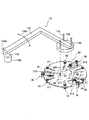
次に、上記第1の搬送装置13について、図2乃至図6を参照して説明する。 第1の搬送装置13は、L字状の作動アーム131を備えている。このL字状の作動アーム131は、その一端部が昇降手段132に連結されている。昇降手段132は例えばエアピストン等からなっており、作動アーム131を図2において矢印130aで示すように上下方向に作動せしめる。また、作動アーム131の一端部と連結した昇降手段132は、正転・逆転可能な電動モータを含む移動機構133に連結されている。従って、移動機構133を正転方向または逆転方向に駆動することにより、作動アーム131は昇降手段132を中心として図2において矢印130bで示す方向に揺動せしめられる。この結果、作動アーム131は水平面内で作動せしめられ、この作動アーム131の他端部に装着部材135を介して装着される後述する吸引保持機構20が水平面内において、上記位置合わせ機構12と上記チャックテーブル3および上記洗浄手段14との間を移動せしめられる。   Next, the first transport device 13 will be described with reference to FIGS. The first transfer device 13 includes an L-shaped operating arm 131. One end of the L-shaped operating arm 131 is connected to the elevating means 132. The elevating means 132 is, for example, an air piston or the like, and operates the operating arm 131 in a vertical direction as shown by an arrow 130a in FIG. The elevating means 132 connected to one end of the operation arm 131 is connected to a moving mechanism 133 including an electric motor capable of rotating forward and backward. Therefore, by driving the moving mechanism 133 in the normal rotation direction or the reverse rotation direction, the operating arm 131 is swung in the direction indicated by the arrow 130b in FIG. As a result, the operating arm 131 is operated in a horizontal plane, and the suction holding mechanism 20 described later attached to the other end of the operating arm 131 via the mounting member 135 is connected to the positioning mechanism 12 in the horizontal plane. It is moved between the chuck table 3 and the cleaning means 14.

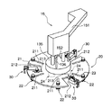
上記作動アーム131の他端部に装着部材135を介して装着される吸引保持機構20は、図2に示すように円盤状の板状物保持部材21を具備している。板状物保持部材21の中心領域下面には、3個の非接触式吸引保持器24が配設されている。非接触式吸引保持器24は、図3に示すように円盤状の本体241と、該本体241の中心部に空気を下面に沿って噴出するノズル242と、本体241にノズル242と連通して形成された空気供給通路243とからなっている。なお、非接触式吸引保持器24を構成する本体241の上面には、空気供給通路243に連通する接続部244が突出して設けられている。この非接触式吸引保持器24は、空気供給通路243を通してノズル242から本体241の下面に沿って空気が噴出されると、中心部には負圧が発生し、この負圧によって板状物が引き寄せられるが、板状物が接近すると本体241の下面と板状物との間を流れる空気が反発力として作用し板状物との接触が阻止され非接触で板状物を吸引保持する。このように構成された非接触式吸引保持器24は、板状物保持部材21の中心領域下面に装着され、接続部244が板状物保持部材21に設けられた穴(図示せず)を挿通して配設される。また、接続部244は、上記装着部材135に設けられた穴(図示せず)にも挿通して配設され、後述するエアー供給手段と連通されたフレキシブルパイプ136に接続される。なお、非接触式吸引保持器24は、板状物の中央領域を広く安定して吸引するために少なくとも3個が望ましい。   The suction holding mechanism 20 mounted on the other end of the operation arm 131 via the mounting member 135 includes a disk-shaped plate-like material holding member 21 as shown in FIG. On the lower surface of the central region of the plate-like material holding member 21, three non-contact suction holders 24 are provided. As shown in FIG. 3, the non-contact type suction holder 24 includes a disc-shaped main body 241, a nozzle 242 for ejecting air to the center of the main body 241 along the lower surface, and a main body 241 that communicates with the nozzle 242. The air supply passage 243 is formed. A connecting portion 244 that communicates with the air supply passage 243 protrudes from an upper surface of the main body 241 that forms the non-contact suction holder 24. When air is ejected from the nozzle 242 along the lower surface of the main body 241 through the air supply passage 243, a negative pressure is generated at the center of the non-contact suction holder 24, and a plate-like object is generated by the negative pressure. However, when the plate-like object approaches, the air flowing between the lower surface of the main body 241 and the plate-like object acts as a repulsive force, so that the contact with the plate-like object is prevented and the plate-like object is sucked and held without contact. The non-contact type suction holder 24 thus configured is mounted on the lower surface of the central region of the plate-like object holding member 21, and the connection part 244 is formed in a hole (not shown) provided in the plate-like object holder 21. It is arranged to be inserted. The connection portion 244 is also inserted through a hole (not shown) provided in the mounting member 135, and is connected to a flexible pipe 136 that communicates with an air supply unit described later. The number of the non-contact type suction holders 24 is desirably at least three in order to widely and stably suction the central region of the plate-like object.

上記板状物保持部材21の外周部には、径方向に長い複数個の長穴211が放射状に周方向に等間隔で形成されている。この長穴211には、板状物保持部材21の外周領域下面に配設され半導体ウエーハ等の板状物の外周部上面に接触して板状物の水平方向移動を規制する規制手段として機能する外周支持部材22がそれぞれ装着されている。この外周支持部材22は、図4に示すように直方体状の移動ブロック221と、該移動ブロック221の下面に装着されたラバーシート222とからなっている。移動ブロック221は、その上面に上記長穴211に嵌合する被案内突起221aが設けられているとともに、ネジ穴221bが形成されている。このように構成された外周支持部材22は、板状物保持部材21の下面側から被案内突起221aを長穴211に嵌合し、板状物保持部材21の上面側から長穴211を通して調整ボルト23をネジ穴221bに螺合することによって板状物保持部材21に装着される。この装着時には、調整ボルト23を締めつける前に、外周支持部材22を長穴211に沿って移動し半導体ウエーハ等の板状物の外形寸法に対応する所定位置に位置付けた状態で、調整ボルト23を締めつける。従って、板状物保持部材21に形成された長穴211と調整ボルト23は、外周支持部材22を板状物保持部材21の径方向に移動調整する調整手段として機能する。このように、外周支持部材22は板状物保持部材21の径方向に移動調整可能に構成されているので、搬送する半導体ウエーハ等の板状物の大きさに対応することができる。なお、上記外周支持部材22は、板状物の外周部を安定して支持するために少なくとも3個が望ましい。   A plurality of elongated holes 211 long in the radial direction are formed radially at equal intervals in the circumferential direction on the outer peripheral portion of the plate-like object holding member 21. The elongated hole 211 is provided on the lower surface of the outer peripheral region of the plate-like object holding member 21 and functions as a restricting means that contacts the upper surface of the outer peripheral portion of the plate-like object such as a semiconductor wafer to restrict the horizontal movement of the plate-like object. The outer peripheral supporting members 22 are mounted respectively. As shown in FIG. 4, the outer peripheral support member 22 includes a rectangular parallelepiped movable block 221 and a rubber sheet 222 mounted on the lower surface of the movable block 221. The moving block 221 has a guided projection 221a fitted on the long hole 211 on the upper surface thereof and a screw hole 221b formed therein. In the outer peripheral supporting member 22 configured as described above, the guided protrusion 221 a is fitted into the elongated hole 211 from the lower surface side of the plate-like object holding member 21, and adjusted through the elongated hole 211 from the upper surface side of the plate-like object holding member 21. The bolt 23 is screwed into the screw hole 221b to be mounted on the plate-like object holding member 21. At this time, before the adjusting bolt 23 is tightened, the adjusting bolt 23 is moved in a state where the outer peripheral supporting member 22 is moved along the elongated hole 211 and is positioned at a predetermined position corresponding to the outer dimensions of a plate-like object such as a semiconductor wafer. Tighten. Therefore, the elongated hole 211 and the adjustment bolt 23 formed in the plate-like object holding member 21 function as an adjusting unit that moves and adjusts the outer peripheral support member 22 in the radial direction of the plate-like object holding member 21. As described above, since the outer peripheral support member 22 is configured to be movable and adjustable in the radial direction of the plate-shaped object holding member 21, it can correspond to the size of the plate-shaped object such as a semiconductor wafer to be conveyed. The number of the outer peripheral support members 22 is desirably at least three in order to stably support the outer peripheral portion of the plate-like object.

図2に示す吸引保持機構20は、板状物保持部材21の外周領域に周方向に所定の間隔をもって配設された複数個(図示の実施形態においては3個)の落下防止手段30を備えている。落下防止手段30は、板状物保持部材21の外周部に周方向に等間隔で径方向に形成された3個の切欠212に沿ってそれぞれ径方向に移動調整可能に配設されている。   The suction holding mechanism 20 shown in FIG. 2 includes a plurality (three in the illustrated embodiment) of drop prevention means 30 arranged at a predetermined interval in a circumferential direction in an outer peripheral region of the plate-shaped object holding member 21. ing. The drop prevention means 30 is provided on the outer peripheral portion of the plate-like object holding member 21 so as to be movable in the radial direction along three notches 212 formed in the radial direction at equal intervals in the circumferential direction.

ここで、落下防止手段30について図5および図6を参照して説明する。図5および図6に示す落下防止手段30は、ハウジング31と、該ハウジング31に一端が揺動可能に支持された支持部材32と、支持部材32を図6において実線で示す保持位置と2点鎖線で示す退避位置に位置付けるエアーピストン機構33とを具備している。ハウジング31の上部には図5に示すように装着部材34が側方に突出して設けられており、この装着部材34にはボルト挿通穴341が形成されている。このよに装着部材34を備えたハウジング31は、板状物保持部材21に設けられた切欠212に沿って配置し、装着部材34を板状物保持部材21の上面に載置する。そして、装着部材34に設けられたボルト挿通穴341に調整ボルト35を挿通するとともに、該調整ボルト35を板状物保持部材21に設けられた上記切欠212と平行に形成された長穴213を挿通し、板状物保持部材21の下側に配設されるナット36に螺合することによって、ハウジング31が板状物保持部材21に装着される。この装着時には、調整ボルト35を締めつける前に、ハウジング31を長穴213に沿って移動し上記外周支持部材22と対応する所定位置に位置付けた状態で、調整ボルト35を締めつける。従って、板状物保持部材21に形成された長穴213と調整ボルト35およびナット36は、ハウジング31即ち落下防止手段30を板状物保持部材21の径方向に移動調整する調整手段として機能する。   Here, the fall prevention means 30 will be described with reference to FIGS. The fall prevention means 30 shown in FIGS. 5 and 6 includes a housing 31, a support member 32 one end of which is swingably supported by the housing 31, and a holding position indicated by a solid line in FIG. And an air piston mechanism 33 positioned at a retracted position indicated by a chain line. As shown in FIG. 5, a mounting member 34 is provided on an upper portion of the housing 31 so as to protrude laterally, and a bolt insertion hole 341 is formed in the mounting member 34. Thus, the housing 31 provided with the mounting member 34 is arranged along the notch 212 provided in the plate-like object holding member 21, and the mounting member 34 is placed on the upper surface of the plate-like object holding member 21. Then, the adjustment bolt 35 is inserted into the bolt insertion hole 341 provided in the mounting member 34, and the adjustment bolt 35 is inserted into the elongated hole 213 formed in parallel with the notch 212 provided in the plate-like object holding member 21. The housing 31 is attached to the plate-like object holding member 21 by being inserted and screwed into a nut 36 provided below the plate-like object holding member 21. At this time, before the adjustment bolt 35 is tightened, the adjustment bolt 35 is tightened while the housing 31 is moved along the elongated hole 213 and positioned at a predetermined position corresponding to the outer peripheral support member 22. Therefore, the elongated hole 213, the adjusting bolt 35, and the nut 36 formed in the plate-like object holding member 21 function as adjusting means for moving and adjusting the housing 31, that is, the drop prevention means 30 in the radial direction of the plate-like object holding member 21. .

次に、上記支持部材32について説明する。支持部材32は、下端に支持爪321を備えており、その上端が上記ハウジング31に設けられた取付部311に支持軸37によって揺動可能に支持される。なお、支持部材32の中間部には、上下方向に長い長穴322が形成されているとともに、該長穴322の上端に円形の挿通穴323が形成されている。   Next, the support member 32 will be described. The support member 32 has a support claw 321 at a lower end, and an upper end thereof is swingably supported by a mounting shaft 311 provided on the housing 31 by a support shaft 37. In addition, a vertically long slot 322 is formed in an intermediate portion of the support member 32, and a circular insertion hole 323 is formed at the upper end of the slot 322.

上記エアーピストン機構33について、図6を参照して説明する。
エアーピストン機構33は、上記ハウジング31に形成されたシリンダ穴331と、該シリンダ穴331に摺動可能に配設されたピストン332と、該ピストン332に一端を連結したピストンロッド333とを具備しており、ピストンロッド333の他端が上記支持部材32に形成された長穴322に係合するようになっている。即ち、ピストンロッド333の他端部には、第1の係合部333aと第2の係合部333bが上記支持部材32の厚さより大きい間隔をおいて設けられており、この第1の係合部333aと第2の係合部333bの間を支持部材32の上記長穴322に遊嵌する。
上記ピストン332の図6において左側に形成される一方の室331aには後述するエアー供給手段38によって適宜エアーが供給されるようになっており、ピストン332の図6において右側に形成される他方の室331bにはピストン332を図6において左方に移動すべく付勢する圧縮コイルスプリング334が配設されている。このように構成されたエアーピストン機構33は、室331aにエアーが供給されない場合には、ピストン332がコイルスプリング334のスプリング力によって図6に示す位置付けられ、上記支持部材32を図6において実線で示す保持位置に位置付ける。一方、一方の室331aにエアーが供給されるとピストン332がコイルスプリング334のスプリング力に抗して図6において右方に移動し、上記支持部材32を支持軸37を中心として反時計方向に回動せしめ、図6において2点鎖線で示す退避位置に位置付ける。なお、上記ハウジング31の支持部材32側の下端部には、支持部材32の図6において実線で示す状態から支持軸37を中心として時計方向への回動を規制するための回動規制部材331cが配設されている。
The air piston mechanism 33 will be described with reference to FIG.
The air piston mechanism 33 includes a cylinder hole 331 formed in the housing 31, a piston 332 slidably disposed in the cylinder hole 331, and a piston rod 333 having one end connected to the piston 332. The other end of the piston rod 333 engages with an elongated hole 322 formed in the support member 32. That is, at the other end of the piston rod 333, a first engagement portion 333a and a second engagement portion 333b are provided at an interval larger than the thickness of the support member 32. The gap between the joint portion 333a and the second engagement portion 333b is loosely fitted in the elongated hole 322 of the support member 32.
Air is appropriately supplied to one chamber 331a formed on the left side of the piston 332 in FIG. 6 by air supply means 38 described later, and the other chamber 331a formed on the right side of the piston 332 in FIG. A compression coil spring 334 for urging the piston 332 to move leftward in FIG. 6 is provided in the chamber 331b. When the air is not supplied to the chamber 331a, the piston 332 is positioned as shown in FIG. 6 by the spring force of the coil spring 334, and the support member 32 is moved by a solid line in FIG. At the indicated holding position. On the other hand, when air is supplied to one of the chambers 331a, the piston 332 moves rightward in FIG. 6 against the spring force of the coil spring 334, and moves the support member 32 counterclockwise around the support shaft 37. Then, it is turned to the retracted position shown by the two-dot chain line in FIG. The lower end of the housing 31 on the support member 32 side is provided with a rotation restricting member 331c for restricting the clockwise rotation of the support member 32 about the support shaft 37 from the state shown by the solid line in FIG. Are arranged.

上記エアー供給手段38は、コンプレッサー381と該コンプレッサー381から吐出された圧縮エアーを貯えるエアータンク382とからなるエアー供給源380を具備している。エアータンク382と上記エアーピストン機構33の一方の室331aは配管383aおよびフレキシブルパイプ383bによって接続されており、配管383aとフレキシブルパイプ383bの間には電磁制御弁384が配設されている。この電磁制御弁384は、除勢(OFF)状態では配管383aとフレキシブルパイプ383bとの連通を遮断してフレキシブルパイプ383bを大気に開放しており、付勢(ON)されると配管383aとフレキシブルパイプ383bを連通するように構成されている。また、上記エアータンク382と上記非接触式吸引保持器24は、配管383aと上記フレキシブルパイプ136によって接続されており、配管383aとフレキシブルパイプ136の間には電磁制御弁385が配設されている。この電磁制御弁385は、除勢(OFF)状態では配管383aとフレキシブルパイプ136とが連通しており、、付勢(ON)されると配管383aとフレキシブルパイプ136との連通を遮断するように構成されている。   The air supply means 38 includes an air supply source 380 including a compressor 381 and an air tank 382 for storing compressed air discharged from the compressor 381. The air tank 382 and one chamber 331a of the air piston mechanism 33 are connected by a pipe 383a and a flexible pipe 383b, and an electromagnetic control valve 384 is provided between the pipe 383a and the flexible pipe 383b. The electromagnetic control valve 384 disconnects the communication between the pipe 383a and the flexible pipe 383b in the de-energized (OFF) state to open the flexible pipe 383b to the atmosphere. It is configured to communicate with the pipe 383b. Further, the air tank 382 and the non-contact type suction holder 24 are connected by a pipe 383a and the flexible pipe 136, and an electromagnetic control valve 385 is provided between the pipe 383a and the flexible pipe 136. . The electromagnetic control valve 385 communicates with the pipe 383a and the flexible pipe 136 in the deenergized (OFF) state, and shuts off the communication between the pipe 383a and the flexible pipe 136 when energized (ON). It is configured.

図示の実施形態におけるエアー供給手段38は、上記エアータンク382内のエアー圧力を検出する圧力検出手段386と、該圧力検出手段386からの検出信号に基づいて上記電磁制御弁384を制御する制御手段387を具備している。なお、制御手段387は、搬送装置の作動を制御するための制御信号が入力されるようになっており、この制御信号に基づいて上記電磁制御弁384、電磁制御弁385および後述する電磁制御弁385aに制御信号を出力する。また、上記配管383aには、手動切換弁388が配設されている。この手動切換弁388は、切削作業開示時にオペレーターによって開かれ、配管383aを連通する。   The air supply means 38 in the illustrated embodiment includes a pressure detection means 386 for detecting the air pressure in the air tank 382 and a control means for controlling the electromagnetic control valve 384 based on a detection signal from the pressure detection means 386. 387. The control means 387 receives a control signal for controlling the operation of the transfer device. Based on the control signal, the electromagnetic control valve 384, the electromagnetic control valve 385, and the electromagnetic control valve 385a to output a control signal. Further, a manual switching valve 388 is provided in the pipe 383a. The manual switching valve 388 is opened by the operator when the cutting operation is disclosed, and communicates with the pipe 383a.

図示の実施形態における吸引保持機構20は以上のように構成されており、その作用について図7を参照して説明する。
吸引保持機構20を板状物である半導体ウエーハ9の上方位置に位置付け、電磁制御弁384を付勢(ON)するとともに電磁制御弁385を除勢(OFF)する。電磁制御弁384が付勢(ON)されると、上述したように配管383aとフレキシブルパイプ383bが連通し、エアータンク382からエアーが上記エアーピストン機構33の一方の室331aに供給される。この結果、上述したようにピストン332がコイルスプリング334のスプリング力に抗して図6において右方に移動し、上記支持部材32を2点鎖線で示す退避位置に位置付ける。即ち、支持部材32は図7において2点鎖線で示す退避位置に位置付けられ、支持爪321が外周支持部材22のラバーシート222の外側上方に位置付けられる。一方、電磁制御弁385が除勢(OFF)されると、上述したように配管383aとフレキシブルパイプ136が連通するため、エアータンク382からエアーが上記3個の非接触式吸引保持器24のそれぞれに供給される。この結果、非接触式吸引保持器24のノズル242から空気が噴出され、図3に示すように各非接触式吸引保持器24の中央部には負圧が発生する。この負圧によって図7に示すように半導体ウエーハ9が吸引されるが、上述したように半導体ウエーハ9が非接触式吸引保持器24に接近すると空気が反発力として作用し半導体ウエーハ9との接触が阻止され非接触で吸引保持される。このようにして半導体ウエーハ9が3個の非接触式吸引保持器24に吸引されると、半導体ウエーハ9の外周縁が板状物保持部材21の外周領域下面に配設された複数個の外周支持部材22を構成するラバーシート222に接触し、半導体ウエーハ9の水平方向移動が規制される。以上のようにして吸引保持機構20に吸引保持された半導体ウエーハ9は、その中央部が3個の非接触式吸引保持器24によって部分的に吸引されるため、中心部が大きく湾曲することがないので、後述するように切削溝が形成されていても割れることはない。
The suction holding mechanism 20 in the illustrated embodiment is configured as described above, and its operation will be described with reference to FIG.
The suction holding mechanism 20 is positioned above the semiconductor wafer 9 which is a plate-like object, and the electromagnetic control valve 384 is energized (ON) and the electromagnetic control valve 385 is deenergized (OFF). When the electromagnetic control valve 384 is energized (ON), the pipe 383a communicates with the flexible pipe 383b as described above, and air is supplied from the air tank 382 to one chamber 331a of the air piston mechanism 33. As a result, as described above, the piston 332 moves rightward in FIG. 6 against the spring force of the coil spring 334, and positions the support member 32 at the retracted position shown by the two-dot chain line. That is, the support member 32 is located at the retracted position indicated by the two-dot chain line in FIG. 7, and the support claw 321 is located above the rubber sheet 222 of the outer peripheral support member 22. On the other hand, when the electromagnetic control valve 385 is deenergized (OFF), the pipe 383a communicates with the flexible pipe 136 as described above, so that air from the air tank 382 is supplied to each of the three non-contact suction holders 24 Supplied to As a result, air is ejected from the nozzle 242 of the non-contact type suction holder 24, and a negative pressure is generated at the center of each non-contact type suction holder 24 as shown in FIG. As shown in FIG. 7, the semiconductor wafer 9 is sucked by this negative pressure. As described above, when the semiconductor wafer 9 approaches the non-contact type suction holder 24, the air acts as a repulsive force and the semiconductor wafer 9 comes into contact with the semiconductor wafer 9. And is sucked and held without contact. When the semiconductor wafer 9 is sucked by the three non-contact type suction holders 24 in this manner, the outer peripheral edge of the semiconductor wafer 9 becomes a plurality of outer peripheral areas disposed on the lower surface of the outer peripheral region of the plate-like object holding member 21. The semiconductor wafer 9 contacts the rubber sheet 222 constituting the support member 22, and the horizontal movement of the semiconductor wafer 9 is regulated. As described above, the central portion of the semiconductor wafer 9 sucked and held by the suction holding mechanism 20 is partially sucked by the three non-contact suction holders 24, so that the center portion may be greatly curved. Since there is no cutting groove, it does not break even if a cutting groove is formed as described later.

上述したように吸引保持機構20によって半導体ウエーハ9を吸引保持し搬送している際に、エアー供給源380を構成するコンプレッサー381が故障した場合について説明する。
コンプレッサー381が故障するとエアータンク382にエアーが供給されないため、エアータンク382内のエアー圧力が低下する。このエアー圧力が所定値以下になると圧力検出手段386からの検出信号に基づいて、制御手段387が電磁制御弁384を除勢(OFF)させる。電磁制御弁384が除勢(OFF)すると上述したように配管383aとフレキシブルパイプ383bとの連通が遮断されてエアーの供給が断たれるとともに、フレキシブルパイプ383bが大気に開放されるため、上記エアーピストン機構33の一方の室331a内のエアーがフレキシブルパイプ383bおよび電磁制御弁384を通して大気に排出される。この結果、上述したようにエアーピストン機構33のピストン332が圧縮コイルスプリング334のスプリング力によって図6に実線で示す保持位置に位置付ける。即ち、支持部材32は図7において2点鎖線で示す退避位置から1点鎖線で示す保持位置に位置付けられる。
A case where the compressor 381 constituting the air supply source 380 breaks down while the semiconductor wafer 9 is suction-held and conveyed by the suction holding mechanism 20 as described above will be described.
If the compressor 381 fails, air is not supplied to the air tank 382, so that the air pressure in the air tank 382 decreases. When the air pressure falls below a predetermined value, the control means 387 deactivates (turns off) the electromagnetic control valve 384 based on the detection signal from the pressure detection means 386. When the electromagnetic control valve 384 is deenergized (OFF), as described above, the communication between the pipe 383a and the flexible pipe 383b is cut off, the supply of air is cut off, and the flexible pipe 383b is opened to the atmosphere. Air in one chamber 331a of the piston mechanism 33 is discharged to the atmosphere through the flexible pipe 383b and the electromagnetic control valve 384. As a result, as described above, the piston 332 of the air piston mechanism 33 is positioned at the holding position indicated by the solid line in FIG. 6 by the spring force of the compression coil spring 334. That is, the support member 32 is positioned from the retracted position shown by the two-dot chain line in FIG. 7 to the holding position shown by the one-dot chain line.

一方、エアータンク382内のエアー圧力が低下しても大気圧になるまでは非接触式吸引保持器24へエアーが供給されている。従って、僅かな時間ではあるが非接触式吸引保持器24による吸引機能が維持される。この間に上記3個の落下防止手段30の支持部材32が図7において1点鎖線で示す保持位置に位置付けられているので、非接触式吸引保持器24による吸引機能が喪失したときには、半導体ウエーハ9は1点鎖線で示すように支持部材32の支持爪321によって保持される。従って、吸引保持機構20によって半導体ウエーハ9を吸引保持し搬送している際にコンプレッサー351が故障した場合においても、半導体ウエーハ9が落下することはない。   On the other hand, even if the air pressure in the air tank 382 decreases, the air is supplied to the non-contact type suction holder 24 until the pressure becomes the atmospheric pressure. Therefore, the suction function of the non-contact suction holder 24 is maintained for a short time. During this time, the support members 32 of the three fall prevention means 30 are positioned at the holding positions indicated by the dashed line in FIG. 7, so that when the suction function of the non-contact suction holder 24 is lost, the semiconductor wafer 9 Is held by the support claws 321 of the support member 32 as indicated by the dashed line. Therefore, even if the compressor 351 breaks down while the semiconductor wafer 9 is suction-held and transported by the suction holding mechanism 20, the semiconductor wafer 9 does not fall.

次に、上述したように吸引保持機構20によって半導体ウエーハ9を吸引保持し搬送している際に、電源が遮断された場合について説明する。
電源が遮断すると、エアー供給源380を構成するコンプレッサー381が停止するとともに、制御手段387による制御が不能となる。従って、電磁制御弁384および電磁制御弁385は、除勢(OFF)状態となる。この結果、配管383aとフレキシブルパイプ383bとの連通が遮断されてエアーの供給が断たれるとともに、フレキシブルパイプ383bが大気に開放されるため、上述したように支持部材32は図7において2点鎖線で示す退避位置から1点鎖線で示す保持位置に位置付けられる。
Next, a case where the power is shut off while the semiconductor wafer 9 is being suctioned and held by the suction holding mechanism 20 as described above will be described.
When the power supply is cut off, the compressor 381 constituting the air supply source 380 stops and the control by the control unit 387 becomes impossible. Therefore, the electromagnetic control valve 384 and the electromagnetic control valve 385 are in the deenergized (OFF) state. As a result, the communication between the pipe 383a and the flexible pipe 383b is cut off, the supply of air is cut off, and the flexible pipe 383b is opened to the atmosphere. As described above, the support member 32 is a two-dot chain line in FIG. Is positioned at the holding position indicated by the one-dot chain line from the retracted position indicated by.

一方、コンプレッサー381が停止してエアータンク382にエアーが供給されなくなるが、エアータンク382内に貯えられているエアーの圧力が大気圧になるまでは非接触式吸引保持器24へエアーが供給されるので、非接触式吸引保持器24による吸引機能が維持される。この間に上記3個の落下防止手段30の支持部材32が図7において1点鎖線で示す保持位置に位置付けられているので、非接触式吸引保持器24による吸引機能が喪失したときには、半導体ウエーハ9は1点鎖線で示すように支持部材32の支持爪321によって保持される。従って、図示の実施形態においては吸引保持機構20によって半導体ウエーハ9を吸引保持し搬送している際に電源が遮断された場合においても、半導体ウエーハ9が落下することはない。   On the other hand, although the compressor 381 stops and no air is supplied to the air tank 382, the air is supplied to the non-contact type suction holder 24 until the pressure of the air stored in the air tank 382 becomes the atmospheric pressure. Therefore, the suction function of the non-contact suction holder 24 is maintained. During this time, the support members 32 of the three fall prevention means 30 are positioned at the holding positions indicated by the dashed line in FIG. 7, so that when the suction function of the non-contact suction holder 24 is lost, the semiconductor wafer 9 Is held by the support claws 321 of the support member 32 as indicated by the dashed line. Therefore, in the illustrated embodiment, the semiconductor wafer 9 does not fall even when the power is shut off while the semiconductor wafer 9 is being suction-held and transported by the suction-holding mechanism 20.

次に、第2の搬送機構15について、図8を参照して説明する。
図示の実施形態における第2の搬送機構15は、作動アーム151を備えている。この作動アーム151は、その一端部が図示しない従来から用いられている往復移動機構に連結されている。従って、作動アーム151の他端部に装着される後述する吸引保持機構20が水平面内において、上記洗浄手段14と上記チャックテーブル3との間を移動せしめられる。作動アーム151の他端部に装着される吸引保持機構20は、上記図2乃至図7に示す第1の搬送機構13の吸引保持機構20と実質的に同一の構成であり、従って、同一部材には同一符号を付してその説明は省略する。吸引保持機構20を構成する板状物保持部材21の上面に取り付けられる装着部材135は、作動アーム151の他端部に配設された昇降手段152に装着されている。この昇降手段152は、例えばエアピストン等からなっている。このように構成された第2の搬送機構15の吸引保持機構20は、図6に示すエアー供給手段38に作動せしめられる。なお、第2の搬送機構15の吸引保持機構20を構成するエアーピストン機構33はフレキシブルパイプ383bが上記電磁制御弁384に接続されているが、非接触式吸引保持器24はフレキシブルパイプ136が電磁制御弁385aを介して上記配管383aに接続されている。
Next, the second transport mechanism 15 will be described with reference to FIG.
The second transport mechanism 15 in the illustrated embodiment has an operating arm 151. One end of the operation arm 151 is connected to a conventional reciprocating mechanism (not shown). Therefore, a suction holding mechanism 20 described later attached to the other end of the operation arm 151 is moved between the cleaning means 14 and the chuck table 3 in a horizontal plane. The suction holding mechanism 20 attached to the other end of the operation arm 151 has substantially the same configuration as the suction holding mechanism 20 of the first transport mechanism 13 shown in FIGS. Are denoted by the same reference numerals, and description thereof is omitted. The mounting member 135 mounted on the upper surface of the plate-shaped object holding member 21 constituting the suction holding mechanism 20 is mounted on the lifting / lowering means 152 provided at the other end of the operation arm 151. The elevating means 152 is composed of, for example, an air piston or the like. The suction holding mechanism 20 of the second transport mechanism 15 configured as described above is operated by the air supply means 38 shown in FIG. The air pipe mechanism 33 of the suction holding mechanism 20 of the second transport mechanism 15 has a flexible pipe 383b connected to the electromagnetic control valve 384. The control valve 385a is connected to the pipe 383a.

本発明に従って構成された板状物の搬送装置を装備した切削装置は以上のように構成されており、以下その作用について図1を参照して説明する。
半導体ウエーハ9の切削を行うに際しては、半導体ウエーハ9を収容したカセット本体7を搬出入開口71を仮置き領域側に向けてカセット載置機構8のカセットテーブル81上に載置することにより、切削作業の準備が完了する。なお、切削作業を開始する際には、オペレーターによって上記手動切換弁388が開かれ、配管383aが連通される。
そして、切削作業の開始指令がなされると、電磁制御弁384が付勢(ON)され第1の搬送機構13および第2の搬送機構15の落下防止手段30の支持部材が上述したように図7において2点鎖線で示す退避位置に位置付けられる。この状態は切削作業の開始指令が解除されるまで維持される。また、切削作業の開始指令がなされると、電磁制御弁385および電磁制御弁385aが付勢(ON)され第1の搬送機構13および第2の搬送機構15の非接触式吸引保持器24へのエアーの供給が断たれる。そして、被加工物搬出機構11が進退作動してカセット本体7の所定位置に収容された半導体ウエーハ9を位置合わせ機構12に搬送する。位置合わせ機構12に搬送された半導体ウエーハ9は、ここで中心位置合わせされた後、第1の搬送装置13によって上記チャックテーブル3を構成する吸着チャック3bの載置面上に搬送される。即ち、第1の搬送装置13を構成する昇降手段132および移動機構133(図2参照)を作動して吸引保持機構20を位置合わせ機構12で位置合わせされた半導体ウエーハ9の上方に位置付け、電磁制御弁385を除勢(OFF)する。この結果、上述したように落下防止手段30を構成する支持部材32が図7において2点鎖線で示す退避位置に位置付けられいるので、上述したように吸引保持機構20によって半導体ウエーハ9が吸引保持される。このようにして、吸引保持機構20が半導体ウエーハ9を吸引保持したならば、上記昇降手段132および移動機構133を作動せしめて吸引保持機構20に吸引保持されている半導体ウエーハ9を上記チャックテーブル3を構成する吸着チャック3bの載置面上に搬送する。
The cutting device equipped with the plate-like object transfer device configured according to the present invention is configured as described above, and its operation will be described below with reference to FIG.
When the semiconductor wafer 9 is cut, the cassette body 7 containing the semiconductor wafer 9 is mounted on the cassette table 81 of the cassette mounting mechanism 8 with the loading / unloading opening 71 facing the temporary storage area. Preparation for work is completed. When the cutting operation is started, the manual switching valve 388 is opened by the operator, and the pipe 383a is connected.
Then, when a command to start the cutting operation is issued, the electromagnetic control valve 384 is urged (ON), and the support members of the fall prevention means 30 of the first transport mechanism 13 and the second transport mechanism 15 are moved as described above. 7 is positioned at the retracted position indicated by the two-dot chain line. This state is maintained until the start command of the cutting operation is released. Further, when a command to start the cutting operation is issued, the electromagnetic control valve 385 and the electromagnetic control valve 385a are urged (ON) to the non-contact type suction holder 24 of the first transport mechanism 13 and the second transport mechanism 15. Supply of air is cut off. Then, the workpiece unloading mechanism 11 moves forward and backward to transfer the semiconductor wafer 9 stored at a predetermined position of the cassette body 7 to the positioning mechanism 12. The semiconductor wafer 9 transported to the alignment mechanism 12 is center-aligned here, and then transported by the first transport device 13 onto the mounting surface of the suction chuck 3b constituting the chuck table 3. That is, the lifting / lowering means 132 and the moving mechanism 133 (see FIG. 2) constituting the first transfer device 13 are operated to position the suction holding mechanism 20 above the semiconductor wafer 9 positioned by the positioning mechanism 12, and the electromagnetic force is applied. The control valve 385 is deenergized (OFF). As a result, as described above, since the support member 32 constituting the fall prevention means 30 is located at the retracted position indicated by the two-dot chain line in FIG. 7, the semiconductor wafer 9 is suction-held by the suction holding mechanism 20 as described above. You. In this way, when the suction holding mechanism 20 sucks and holds the semiconductor wafer 9, the elevating means 132 and the moving mechanism 133 are operated to move the semiconductor wafer 9 sucked and held by the suction holding mechanism 20 to the chuck table 3. Is transported onto the mounting surface of the suction chuck 3b.

上記のようにして第1の搬送装置13によってチャックテーブル3の吸着チャック3b上に搬送された半導体ウエーハ9は、第1の搬送装置13を構成する吸引保持機構20による吸引保持が解除される。即ち、上記エアー供給手段38の電磁制御弁385が付勢(ON)される。このとき、上述したようにエアー供給手段38の電磁制御弁384は付勢(ON)されており、支持部材32は図7において2点鎖線で示す退避位置に維持されている。そして、チャックテーブル3の吸着チャック3b上に載置された半導体ウエーハ9は、図示しない吸引手段によって吸着チャック3bに吸引保持される。このようにして半導体ウエーハ9を吸引保持したチャックテーブル3は、撮像機構5の直下まで移動せしめられる。チャックテーブル3が撮像機構5の直下に位置付けられると、撮像機構5によって半導体ウエーハ9に形成されている切断ラインが検出され、スピンドルユニット4を割り出し方向である矢印Y方向に移動調節して精密位置合わせ作業が行われる。   As described above, the semiconductor wafer 9 conveyed onto the suction chuck 3b of the chuck table 3 by the first transfer device 13 is released from the suction holding by the suction holding mechanism 20 constituting the first transfer device 13. That is, the electromagnetic control valve 385 of the air supply means 38 is energized (ON). At this time, as described above, the electromagnetic control valve 384 of the air supply means 38 is urged (ON), and the support member 32 is maintained at the retracted position shown by the two-dot chain line in FIG. Then, the semiconductor wafer 9 placed on the suction chuck 3b of the chuck table 3 is suction-held by the suction chuck 3b by suction means (not shown). The chuck table 3 holding the semiconductor wafer 9 by suction in this manner is moved to a position immediately below the imaging mechanism 5. When the chuck table 3 is positioned immediately below the image pickup mechanism 5, the image pickup mechanism 5 detects a cutting line formed on the semiconductor wafer 9, and moves and adjusts the spindle unit 4 in the direction of the arrow Y, which is the indexing direction, to adjust the precision position. A matching operation is performed.

その後、切削ブレード43を所定の方向に回転させつつ、半導体ウエーハ9を吸引保持したチャックテーブル3を切削送り方向である矢印Xで示す方向(切削ブレード43の回転軸と直交する方向)に所定の切削送り速度で移動することにより、チャックテーブル3に保持された半導体ウエーハ8の表面にストリートに沿って半導体チップの仕上がり厚さに相当する深さの切削溝を形成する。即ち、切削ブレード43は割り出し方向である矢印Yで示す方向および切り込み方向である矢印Zで示す方向に移動調整されて位置決めされたスピンドルユニット4に装着され、回転駆動されているので、チャックテーブル3を切削ブレード43の下側に沿って切削送り方向に移動することにより、チャックテーブル3に保持された半導体ウエーハ8は切削ブレード43によりストリートに沿って所定の切り込み深さで切削される。このようにして半導体ウエーハ9の表面にストリートに沿って切削溝が形成されたならば、半導体ウエーハ9を保持したチャックテーブル3は、最初に半導体ウエーハ9を吸引保持した位置に戻され、ここで半導体ウエーハ9の吸引保持を解除する。   Thereafter, while rotating the cutting blade 43 in a predetermined direction, the chuck table 3 holding the semiconductor wafer 9 by suction is moved in a predetermined direction in a direction indicated by an arrow X (a direction orthogonal to the rotation axis of the cutting blade 43) which is a cutting feed direction. By moving at the cutting feed speed, a cutting groove having a depth corresponding to the finished thickness of the semiconductor chip is formed on the surface of the semiconductor wafer 8 held on the chuck table 3 along the street. That is, the cutting blade 43 is mounted on the spindle unit 4 which is moved and adjusted in the direction indicated by the arrow Y which is the indexing direction and the direction indicated by the arrow Z which is the cutting direction, and is rotationally driven. Is moved along the lower side of the cutting blade 43 in the cutting feed direction, so that the semiconductor wafer 8 held on the chuck table 3 is cut by the cutting blade 43 at a predetermined cutting depth along the street. When the cutting grooves are formed along the streets on the surface of the semiconductor wafer 9 in this manner, the chuck table 3 holding the semiconductor wafer 9 is first returned to the position where the semiconductor wafer 9 is sucked and held. The suction holding of the semiconductor wafer 9 is released.

次に、チャックテーブル3上において吸引保持が解除された半導体ウエーハ8は、第2の搬送装置15によって上記洗浄手段14に搬送される。即ち、第2の搬送装置15を構成する昇降手段152および図示しない往復移動機構を作動して吸引保持機構20をチャックテーブル3上に載置されている半導体ウエーハ9の上方に位置付け、上記エアー供給手段38の電磁制御弁385aを除勢(OFF)する。この結果、上述したように落下防止手段30を構成する支持部材32が図7において2点鎖線で示す退避位置に位置付けられいるので、上述したように吸引保持機構20によって半導体ウエーハ9が吸引保持される。このようにして、吸引保持機構20が半導体ウエーハ9を吸引保持したならば、昇降手段152および図示しない往復移動機構を作動せしめて吸引保持機構20に吸引保持されている半導体ウエーハ9を上記洗浄手段14に搬送する。このとき、吸引保持機構20に吸引保持される半導体ウエーハ9は、上述したようにその中央部が3個の非接触式吸引保持器24によって部分的に吸引されるため、中心部が大きく湾曲することがないので、大きな曲げモーメントが生ずることがなく、その表面に切削溝が形成されていても割れることはない。このようにして、吸引保持機構20に吸引保持された半導体ウエーハ9が洗浄手段14に搬送されたならば、上記エアー供給手段38の電磁制御弁385aが付勢(ON)され、吸引保持機構20による半導体ウエーハ9の吸引保持が解除される。   Next, the semiconductor wafer 8 whose suction holding has been released on the chuck table 3 is transported to the cleaning means 14 by the second transport device 15. That is, the suction / holding mechanism 20 is positioned above the semiconductor wafer 9 placed on the chuck table 3 by operating the lifting / lowering means 152 and the not-shown reciprocating mechanism constituting the second transfer device 15, and the air supply The electromagnetic control valve 385a of the means 38 is deenergized (OFF). As a result, as described above, since the support member 32 constituting the fall prevention means 30 is located at the retracted position shown by the two-dot chain line in FIG. 7, the semiconductor wafer 9 is suction-held by the suction holding mechanism 20 as described above. You. In this manner, when the suction holding mechanism 20 sucks and holds the semiconductor wafer 9, the lifting / lowering means 152 and a reciprocating mechanism (not shown) are operated to remove the semiconductor wafer 9 sucked and held by the suction holding mechanism 20 from the cleaning means. To 14. At this time, the central portion of the semiconductor wafer 9 sucked and held by the suction holding mechanism 20 is largely curved by the three non-contact suction holders 24 as described above. Therefore, a large bending moment does not occur, and no crack occurs even if a cutting groove is formed on the surface. When the semiconductor wafer 9 sucked and held by the suction holding mechanism 20 is conveyed to the cleaning means 14 in this manner, the electromagnetic control valve 385a of the air supply means 38 is energized (ON), and the suction holding mechanism 20 is turned on. , The suction holding of the semiconductor wafer 9 is released.

上記のようにして洗浄手段14に搬送された半導体ウエーハ9は、洗浄手段14によって上記切削時に生成されたコンタミが洗浄除去される。洗浄手段14によって洗浄された半導体ウエーハ9は、上記第1の搬送機構13によって上記位置合わせ機構12に搬送される。即ち、第1の搬送装置13を構成する昇降手段132および移動機構133(図2参照)を作動して吸引保持機構20を洗浄手段14によって洗浄された半導体ウエーハ9の上方に位置付け、上記エアー供給手段38の電磁制御弁385を除勢(OFF)する。この結果、上述したように落下防止手段30を構成する支持部材32が図7において2点鎖線で示す退避位置に位置付けられいるので、上述したように吸引保持機構20によって半導体ウエーハ9が吸引保持される。このようにして、吸引保持機構20が半導体ウエーハ9を吸引保持したならば、上記昇降手段132および移動機構133を作動せしめて吸引保持機構20に吸引保持されている半導体ウエーハ9を位置合わせ機構12に搬送する。このとき、第1の搬送機構13を構成する吸引保持機構20に吸引保持される半導体ウエーハ9は、上述したようにその中央部が3個の非接触式吸引保持器24によって部分的に吸引されるため、中心部が大きく湾曲することがないので、大きな曲げモーメントが生ずることがなく、その表面に切削溝が形成されていても割れることはない。位置合わせ機構12に搬送された半導体ウエーハ9は、被加工物搬出手段11によってカセット7の所定位置に収納される。   The semiconductor wafer 9 conveyed to the cleaning unit 14 as described above is cleaned and removed by the cleaning unit 14 of the contamination generated during the cutting. The semiconductor wafer 9 cleaned by the cleaning means 14 is transferred to the alignment mechanism 12 by the first transfer mechanism 13. That is, the lifting / lowering means 132 and the moving mechanism 133 (see FIG. 2) constituting the first transfer device 13 are operated to position the suction holding mechanism 20 above the semiconductor wafer 9 cleaned by the cleaning means 14 and to supply the air. The electromagnetic control valve 385 of the means 38 is deenergized (OFF). As a result, as described above, since the support member 32 constituting the fall prevention means 30 is located at the retracted position shown by the two-dot chain line in FIG. 7, the semiconductor wafer 9 is suction-held by the suction holding mechanism 20 as described above. You. When the suction and holding mechanism 20 suctions and holds the semiconductor wafer 9 in this manner, the elevating means 132 and the moving mechanism 133 are operated to move the semiconductor wafer 9 sucked and held by the suction and holding mechanism 20 to the positioning mechanism 12. Transport to At this time, the semiconductor wafer 9 sucked and held by the suction holding mechanism 20 constituting the first transport mechanism 13 is partially suctioned at its central portion by the three non-contact suction holders 24 as described above. Therefore, since the central portion does not bend significantly, a large bending moment does not occur, and there is no crack even if a cutting groove is formed on the surface. The semiconductor wafer 9 conveyed to the positioning mechanism 12 is stored in a predetermined position of the cassette 7 by the workpiece unloading means 11.

以上のように、図示の実施形態においては、落下防止手段30の支持部材32が作業終了まで図7において2点鎖線で示す退避位置に位置付けられており、第1の搬送機構13または第2の搬送機構15の吸引保持機構20に半導体ウエーハ9が保持されている状態で、コンプレッサー381が故障したり電源が遮断した場合には、上述したように上記支持部材32が図7において1点鎖線で示す保持位置に位置付けられるので、吸引保持機構20による吸引機能が喪失しても半導体ウエーハ9は支持部材32によって支持され落下することがない。   As described above, in the illustrated embodiment, the support member 32 of the fall prevention unit 30 is positioned at the retracted position indicated by the two-dot chain line in FIG. 7 until the operation is completed, and the first transport mechanism 13 or the second In the state where the semiconductor wafer 9 is held by the suction holding mechanism 20 of the transport mechanism 15, if the compressor 381 fails or the power is shut off, as described above, the support member 32 is indicated by a dashed line in FIG. Since the semiconductor wafer 9 is positioned at the indicated holding position, the semiconductor wafer 9 is supported by the support member 32 and does not drop even if the suction function of the suction holding mechanism 20 is lost.

本発明に従って構成された板状物の搬送装置を装備したダイシング装置としての切削装置の斜視図。1 is a perspective view of a cutting device as a dicing device equipped with a plate-like object transfer device configured according to the present invention. 本発明に従って構成された搬送機構としての第1の搬送装置の吸引保持機構を分解して示す斜視図。FIG. 3 is an exploded perspective view showing a suction holding mechanism of a first transport device as a transport mechanism configured according to the present invention. 図2に示す吸引保持機構を構成する非接触式吸引保持器の断面図。FIG. 3 is a cross-sectional view of a non-contact suction holder that constitutes the suction holding mechanism shown in FIG. 2. 図2に示す吸引保持機構を構成する外周支持部材および調整ネジの斜視図。FIG. 3 is a perspective view of an outer peripheral support member and an adjustment screw that constitute the suction holding mechanism shown in FIG. 2. 図2に示す吸引保持機構を構成する落下防止手段の斜視図。FIG. 3 is a perspective view of a fall prevention unit included in the suction holding mechanism illustrated in FIG. 2. 図2に示す吸引保持機構を構成する落下防止手段とエアー供給手段の関係を示す概略構成図。FIG. 3 is a schematic configuration diagram illustrating a relationship between a fall prevention unit and an air supply unit that configure the suction holding mechanism illustrated in FIG. 2. 図2に示す吸引保持機構により板状物を吸引保持した状態を示す断面図。FIG. 3 is a cross-sectional view illustrating a state where the plate-shaped object is suction-held by the suction-holding mechanism illustrated in FIG. 2. 本発明に従って構成された搬送機構としての第2の搬送装置の吸引保持機構を示す斜視図。FIG. 4 is a perspective view showing a suction holding mechanism of a second transport device as a transport mechanism configured according to the present invention.

符号の説明Explanation of reference numerals

2:装置ハウジング
3:チャックテーブル
4:スピンドルユニット
41:スピンドルハウジング
42:回転スピンドル
43:切削ブレード
5:撮像機構
6:表示手段
7:カセット
8:カセット載置機構
9:半導体ウエーハ
11:被加工物搬出機構
12:位置合わせ機構
13:第1の搬送装置
131:作動アーム
132:昇降手段
133:移動機構
14:洗浄手段
15:第2の搬送機構
151:作動アーム
20:吸引保持機構
21:板状物保持部材
22:外周支持部材
24:非接触式吸引保持器
30:落下防止手段
32:支持部材
33:エアーピストン機構
332:ピストン
333:ピストンロッド
334:圧縮コイルスプリング
38:エアー供給手段
380:エアー供給源
381:コンプレッサー
382:エアータンク
384:電磁制御弁
385:電磁制御弁
386:圧力検出手段
387:制御手段
388:手動切換弁
2: Device housing 3: Chuck table 4: Spindle unit 41: Spindle housing 42: Rotating spindle 43: Cutting blade 5: Imaging mechanism 6: Display means 7: Cassette 8: Cassette mounting mechanism 9: Semiconductor wafer 11: Workpiece Unloading mechanism 12: Positioning mechanism 13: First transport device 131: Operating arm 132: Elevating means 133: Moving mechanism 14: Cleaning means 15: Second transport mechanism 151: Operating arm 20: Suction holding mechanism 21: Plate shape Object holding member 22: Peripheral support member 24: Non-contact type suction holder 30: Fall prevention means 32: Support member 33: Air piston mechanism 332: Piston 333: Piston rod 334: Compression coil spring 38: Air supply means 380: Air Source 381: Compressor 382: Air Tan 384: electromagnetic control valve 385: electromagnetic control valve 386: pressure detecting means 387: control means 388: manual switching valve

Claims (6)

板状物を吸引保持する吸引保持機構と、該吸引保持機構を第1の所定位置と第2の所定位置との間を移動せしめる移動機構と、を具備する板状物の搬送装置において、
該吸引保持機構は、板状物保持部材と、該板状物保持部材の中心領域下面に配設された非接触式吸引保持器と、該板状物保持部材の外周領域下面に配設され板状物の水平方向移動を規制する規制手段と、該板状物保持部材の外周領域に周方向に所定の間隔をもって配設され該非接触式吸引保持器によって吸引された板状物の落下を防止する複数個の落下防止手段と、を備えている、
ことを特徴とする板状物の搬送装置。
In a plate-like object transport device, comprising: a suction holding mechanism that sucks and holds a plate-like object; and a moving mechanism that moves the suction holding mechanism between a first predetermined position and a second predetermined position.
The suction holding mechanism is provided on a plate-like object holding member, a non-contact type suction holder provided on a lower surface of a central region of the plate-like material holding member, and provided on a lower surface of an outer peripheral region of the plate-like material holding member. Regulating means for regulating the horizontal movement of the plate-like material, and a plate-like material which is disposed at a predetermined interval in the circumferential direction in an outer peripheral area of the plate-like material holding member and which is sucked by the non-contact type suction holder, A plurality of fall prevention means for preventing
A plate-like object conveying device characterized by the above-mentioned.
該落下防止手段は、該非接触式吸引保持器によって吸引された板状物の外周部下面を支持する保持位置と該保持位置から該板状物保持部材の径方向外方に退避する退避位置に移動可能に構成された支持部材と、該支持部材を該保持位置と該退避位置に作動せしめるエアーピストン機構とからなっている、請求項1記載の板状物の搬送装置。   The fall prevention means is provided at a holding position for supporting a lower surface of an outer peripheral portion of the plate-like material sucked by the non-contact type suction holder, and a retreat position for retreating from the holding position to a radially outward position of the plate-like material holding member. The plate-like object conveying device according to claim 1, further comprising a movable supporting member, and an air piston mechanism for operating the supporting member to the holding position and the retracted position. 該エアーピストン機構は、該支持部材を該保持位置に向けて付勢するスプリングを具備しており、エアーが供給されると該スプリングのスプリング力に抗して該支持部材を該退避位置に位置付け、エアーの供給が絶たれると該スプリングのスプリング力によって該支持部材を該保持位置に位置付ける、請求項2記載の板状物の搬送装置。   The air piston mechanism includes a spring that biases the support member toward the holding position, and positions the support member at the retracted position against the spring force of the spring when air is supplied. 3. The apparatus according to claim 2, wherein the supporting member is positioned at the holding position by the spring force of the spring when the supply of air is cut off. 該エアーピストン機構に供給するエアーは、該非接触式吸引保持器にエアーを供給するエアー供給源を備えたエアー供給手段によって供給されるように構成されている、請求項3記載の板状物の搬送装置。   The plate-like object according to claim 3, wherein the air supplied to the air piston mechanism is configured to be supplied by air supply means having an air supply source for supplying air to the non-contact type suction holder. Transport device. 該エアー供給手段は、該エアー供給源のエアータンクと該エアーピストン機構とを接続する配管に配設された電磁制御弁と、該エアータンク内のエアー圧力を検出する圧力検出手段と、該圧力検出手段からの検出信号に基づいて該電磁制御弁を制御する制御手段とを具備しており、該制御手段は該エアータンク内のエアー圧力が所定値以下になったとき該エアーピストン機構と該エアータンクとの連通を遮断し該エアーピストン機構のエアーを開放するように該電磁制御弁を作動する、請求項4記載の板状物の搬送装置。   The air supply means includes: an electromagnetic control valve disposed in a pipe connecting the air tank of the air supply source and the air piston mechanism; a pressure detection means for detecting an air pressure in the air tank; Control means for controlling the electromagnetic control valve based on a detection signal from the detection means, wherein the control means controls the air piston mechanism and the air piston mechanism when the air pressure in the air tank falls below a predetermined value. The plate-like object conveying device according to claim 4, wherein the electromagnetic control valve is operated so as to shut off communication with an air tank and release air from the air piston mechanism. 該落下防止手段は、該板状物保持部材の径方向に移動調整可能に構成されている、請求項1から5のいずれかに記載の板状物の搬送装置。   6. The plate-like object conveying device according to claim 1, wherein said fall prevention means is configured to be able to adjust the movement of said plate-like member holding member in a radial direction.
JP2004000823A 2003-01-09 2004-01-06 Transport apparatus for plate-like object Pending JP2004235622A (en)

Priority Applications (1)

Application Number Priority Date Filing Date Title
JP2004000823A JP2004235622A (en) 2003-01-09 2004-01-06 Transport apparatus for plate-like object

Applications Claiming Priority (2)

Application Number Priority Date Filing Date Title
JP2003002958 2003-01-09
JP2004000823A JP2004235622A (en) 2003-01-09 2004-01-06 Transport apparatus for plate-like object

Publications (1)

Publication Number Publication Date
JP2004235622A true JP2004235622A (en) 2004-08-19

Family

ID=32964637

Family Applications (1)

Application Number Title Priority Date Filing Date
JP2004000823A Pending JP2004235622A (en) 2003-01-09 2004-01-06 Transport apparatus for plate-like object

Country Status (1)

Country Link
JP (1) JP2004235622A (en)

Cited By (6)

* Cited by examiner, † Cited by third party
Publication number Priority date Publication date Assignee Title
JP2014194991A (en) * 2013-03-28 2014-10-09 Disco Abrasive Syst Ltd Transfer device of plate-like object
JP2017062490A (en) * 2011-12-29 2017-03-30 株式会社ニコン Exposure apparatus, exposure method, and method for manufacturing device
CN107611070A (en) * 2016-07-12 2018-01-19 株式会社迪思科 Transport unit
CN107785297A (en) * 2016-08-24 2018-03-09 株式会社迪思科 Plate object carrying device and processing unit (plant)
JP2018535550A (en) * 2015-10-25 2018-11-29 アプライド マテリアルズ インコーポレイテッドApplied Materials,Incorporated Apparatus and method for loading a substrate into a vacuum processing module, apparatus and method for processing a substrate for a vacuum deposition process in a vacuum processing module, and system for vacuum processing a substrate
JP7390142B2 (en) 2019-09-20 2023-12-01 株式会社Screenホールディングス Substrate processing equipment and substrate transport method

Cited By (9)

* Cited by examiner, † Cited by third party
Publication number Priority date Publication date Assignee Title
JP2017062490A (en) * 2011-12-29 2017-03-30 株式会社ニコン Exposure apparatus, exposure method, and method for manufacturing device
JP2014194991A (en) * 2013-03-28 2014-10-09 Disco Abrasive Syst Ltd Transfer device of plate-like object
JP2018535550A (en) * 2015-10-25 2018-11-29 アプライド マテリアルズ インコーポレイテッドApplied Materials,Incorporated Apparatus and method for loading a substrate into a vacuum processing module, apparatus and method for processing a substrate for a vacuum deposition process in a vacuum processing module, and system for vacuum processing a substrate
CN107611070A (en) * 2016-07-12 2018-01-19 株式会社迪思科 Transport unit
CN107611070B (en) * 2016-07-12 2023-03-28 株式会社迪思科 Conveying unit
CN107785297A (en) * 2016-08-24 2018-03-09 株式会社迪思科 Plate object carrying device and processing unit (plant)
CN107785297B (en) * 2016-08-24 2023-03-28 株式会社迪思科 Plate-like object conveying device and processing device
JP7390142B2 (en) 2019-09-20 2023-12-01 株式会社Screenホールディングス Substrate processing equipment and substrate transport method
US11850623B2 (en) 2019-09-20 2023-12-26 SCREEN Holdings Co., Ltd. Substrate treating apparatus and substrate transporting method

Similar Documents

Publication Publication Date Title
EP0953409B1 (en) Wafer surface machining method and apparatus
JP4634949B2 (en) Wafer holding pad
JP4303041B2 (en) Semiconductor wafer processing equipment
JP5001074B2 (en) Wafer transport mechanism
JP4256132B2 (en) Plate-shaped material transfer device
JP2009043771A (en) Chuck table mechanism and holding method for workpiece
TW202101643A (en) Cutting apparatus and method of changing consumable parts
JP4323129B2 (en) Plate-like material transport mechanism
JP2006032661A (en) Cutting apparatus
CN106057715B (en) Conveying tray for processed object
US6968938B2 (en) Convey device for a plate-like workpiece
US11173631B2 (en) Cutting apparatus
JP4796249B2 (en) Plate-like object conveyance mechanism and dicing apparatus equipped with the conveyance mechanism
JP6202962B2 (en) Cutting equipment
US20220181174A1 (en) Wafer manufacturing apparatus
JP2004235622A (en) Transport apparatus for plate-like object
JP2016154168A (en) Delivery method for workpiece
JP2003282673A (en) Transport device for semiconductor wafer
JP5412261B2 (en) Processing equipment
CN111415862A (en) Workpiece holding method and workpiece processing method
JP5117772B2 (en) Cutting equipment
JP4986511B2 (en) Cutting equipment
JP4847353B2 (en) Wafer processing equipment
JP2003297902A (en) Cassette adaptor
JP7144964B2 (en) Wafer grinding method

Legal Events

Date Code Title Description
A621 Written request for application examination

Free format text: JAPANESE INTERMEDIATE CODE: A621

Effective date: 20061006

A977 Report on retrieval

Free format text: JAPANESE INTERMEDIATE CODE: A971007

Effective date: 20090107

A131 Notification of reasons for refusal

Free format text: JAPANESE INTERMEDIATE CODE: A131

Effective date: 20090113

A521 Written amendment

Free format text: JAPANESE INTERMEDIATE CODE: A523

Effective date: 20090305

A02 Decision of refusal

Free format text: JAPANESE INTERMEDIATE CODE: A02

Effective date: 20090908