JP2004234645A - Monitoring device of image forming apparatus, control method by the monitoring device, program for executing the control method, management device, control method by the management device, and program for executing control method - Google Patents
Monitoring device of image forming apparatus, control method by the monitoring device, program for executing the control method, management device, control method by the management device, and program for executing control method Download PDFInfo
- Publication number
- JP2004234645A JP2004234645A JP2003435644A JP2003435644A JP2004234645A JP 2004234645 A JP2004234645 A JP 2004234645A JP 2003435644 A JP2003435644 A JP 2003435644A JP 2003435644 A JP2003435644 A JP 2003435644A JP 2004234645 A JP2004234645 A JP 2004234645A
- Authority
- JP
- Japan
- Prior art keywords
- module
- version
- information
- monitoring
- Prior art date
- Legal status (The legal status is an assumption and is not a legal conclusion. Google has not performed a legal analysis and makes no representation as to the accuracy of the status listed.)
- Pending
Links
Images


Classifications
-
- H—ELECTRICITY
- H04—ELECTRIC COMMUNICATION TECHNIQUE
- H04N—PICTORIAL COMMUNICATION, e.g. TELEVISION
- H04N1/00—Scanning, transmission or reproduction of documents or the like, e.g. facsimile transmission; Details thereof
- H04N1/00127—Connection or combination of a still picture apparatus with another apparatus, e.g. for storage, processing or transmission of still picture signals or of information associated with a still picture
- H04N1/00204—Connection or combination of a still picture apparatus with another apparatus, e.g. for storage, processing or transmission of still picture signals or of information associated with a still picture with a digital computer or a digital computer system, e.g. an internet server
-
- H—ELECTRICITY
- H04—ELECTRIC COMMUNICATION TECHNIQUE
- H04N—PICTORIAL COMMUNICATION, e.g. TELEVISION
- H04N1/00—Scanning, transmission or reproduction of documents or the like, e.g. facsimile transmission; Details thereof
- H04N1/00127—Connection or combination of a still picture apparatus with another apparatus, e.g. for storage, processing or transmission of still picture signals or of information associated with a still picture
- H04N1/00323—Connection or combination of a still picture apparatus with another apparatus, e.g. for storage, processing or transmission of still picture signals or of information associated with a still picture with a measuring, monitoring or signaling apparatus, e.g. for transmitting measured information to a central location
-
- H—ELECTRICITY
- H04—ELECTRIC COMMUNICATION TECHNIQUE
- H04N—PICTORIAL COMMUNICATION, e.g. TELEVISION
- H04N1/00—Scanning, transmission or reproduction of documents or the like, e.g. facsimile transmission; Details thereof
- H04N1/00962—Input arrangements for operating instructions or parameters, e.g. updating internal software
- H04N1/00973—Input arrangements for operating instructions or parameters, e.g. updating internal software from a remote device, e.g. receiving via the internet instructions input to a computer terminal
-
- H—ELECTRICITY
- H04—ELECTRIC COMMUNICATION TECHNIQUE
- H04N—PICTORIAL COMMUNICATION, e.g. TELEVISION
- H04N1/00—Scanning, transmission or reproduction of documents or the like, e.g. facsimile transmission; Details thereof
- H04N1/00127—Connection or combination of a still picture apparatus with another apparatus, e.g. for storage, processing or transmission of still picture signals or of information associated with a still picture
- H04N1/00344—Connection or combination of a still picture apparatus with another apparatus, e.g. for storage, processing or transmission of still picture signals or of information associated with a still picture with a management, maintenance, service or repair apparatus
-
- H—ELECTRICITY
- H04—ELECTRIC COMMUNICATION TECHNIQUE
- H04N—PICTORIAL COMMUNICATION, e.g. TELEVISION
- H04N2201/00—Indexing scheme relating to scanning, transmission or reproduction of documents or the like, and to details thereof
- H04N2201/0008—Connection or combination of a still picture apparatus with another apparatus
- H04N2201/0034—Details of the connection, e.g. connector, interface
- H04N2201/0037—Topological details of the connection
- H04N2201/0039—Connection via a network
Landscapes
- Engineering & Computer Science (AREA)
- Multimedia (AREA)
- Signal Processing (AREA)
- General Engineering & Computer Science (AREA)
- Computing Systems (AREA)
- Information Transfer Between Computers (AREA)
Abstract
Description
本発明は、画像形成装置の監視装置、該監視装置による制御方法、及び該制御方法を実行するプログラム、並びに管理装置、該管理装置による制御方法、及び該制御方法を実行するプログラムに関し、特に、1台以上の画像形成装置(特に機能複合型複写機を初めとする印刷事務機)を監視下に置き、当該画像形成装置の情報を収集すると共に収集した情報を管理サーバ(管理装置)へ通知する監視装置、該監視装置による制御方法、及び該制御方法を実行するプログラム、並びに1台以上の監視装置を管理下に置き情報を収集する管理装置、該管理装置による制御方法、及び該制御方法を実行するプログラムに関する。 The present invention relates to a monitoring apparatus for an image forming apparatus, a control method by the monitoring apparatus, a program for executing the control method, a management apparatus, a control method by the management apparatus, and a program for executing the control method. At least one image forming apparatus (especially a printing office machine including a multifunction copier) is placed under monitoring, information on the image forming apparatus is collected, and the collected information is notified to a management server (management apparatus). Monitoring device, control method by the monitoring device, program for executing the control method, management device for managing one or more monitoring devices and collecting information, control method by the management device, and the control method Related to a program that executes.
従来、情報処理機能を有する装置(ホスト)と監視装置とを通信媒体により通信可能に構成し、監視装置を介して複写機等の装置の状態を遠隔から監視する遠隔監視システムが存在する。この種の遠隔監視システムにおいては、遠隔地に設置されている監視装置が作動するその内部のモジュール(プログラム)のアップデート(バージョンアップ)を遠隔地から行う方法は存在していたが、その場合、ホストとアップデート対象の監視装置が、互いに通信可能に接続されて、この通信可能に接続された状態で確実にアップデートデータの転送を行って監視装置のモジュールのアップデートを行い、次いでアップデートしたモジュールが所望のモジュールにアップデートされているか否かの確認を行い、ホストと監視装置との接続を切断するというものであった。 2. Description of the Related Art Conventionally, there is a remote monitoring system in which a device (host) having an information processing function and a monitoring device are configured to be able to communicate with each other via a communication medium, and the status of a device such as a copying machine is remotely monitored via the monitoring device. In this type of remote monitoring system, there has been a method of remotely updating (upgrading) an internal module (program) in which a monitoring device installed in a remote location operates, but in that case, The host and the monitoring device to be updated are communicably connected to each other. In this communicatively connected state, the update data is surely transferred to update the module of the monitoring device. It is checked whether the module has been updated, and the connection between the host and the monitoring device is disconnected.
尚、上記に関連した従来例としては各種の提案がなされている(例えば、特許文献1参照。)。
しかしながら、上記従来の遠隔監視システムにおいては次のような問題があった。遠隔監視システムのホストは、複数の監視装置を管理下に置いているため、監視装置のモジュールをアップデートするためにアップデート対象の監視装置1台ずつと通信可能に接続してアップデート処理を行う必要があり、この作業は膨大なものであり、従来技術では円滑にアップデート処理を行うことは困難であった。 However, the conventional remote monitoring system has the following problems. Since the host of the remote monitoring system manages a plurality of monitoring devices, it is necessary to perform an update process by communicatively connecting with one monitoring device to be updated in order to update a module of the monitoring device. This work is enormous, and it has been difficult to perform the update process smoothly with the conventional technology.
本発明は、上述した点に鑑みなされたものであり、管理装置からの遠隔操作により監視装置が作動するモジュールのアップデートを効率よく行うことを可能としたデバイス監視装置、該監視装置による制御方法、及び該制御方法を実行するプログラム、並びに管理装置、該管理装置による制御方法、及び該制御方法を実行するプログラムを提供することを目的とする。 The present invention has been made in view of the above points, and a device monitoring device capable of efficiently updating a module operated by a monitoring device by remote control from a management device, a control method by the monitoring device, It is an object to provide a program for executing the control method, a management device, a control method by the management device, and a program for executing the control method.
上記目的を達成するために、請求項1記載の監視装置は、監視対象とする少なくとも1つの画像形成装置から通信により情報を取得すると共に管理装置と通信可能な監視装置であって、前記管理装置との間で電子メールによる通信を行う電子メール手段と、前記管理装置から電子メールにより、前記監視装置が作動する第1のモジュールをアップデートするための第2のモジュールを前記電子メール手段が受信したことに応じて自動的に作動中の前記第1のモジュールを前記受信した第2のモジュールにアップデートする処理手段と、前記管理装置から電子メールにより前記第1のモジュールのバージョン情報の取得要求を前記電子メール手段が受信した場合、前記バージョン情報を収集する情報収集手段と、前記情報収集手段により収集した前記バージョン情報を電子メールにより前記管理装置に返信する返信手段と、を有することを特徴とする。
To achieve the above object, the monitoring device according to
請求項2記載の監視装置は、請求項1に記載の監視装置において、更に、前記管理装置から、少なくとも前記第2のモジュール及びインストールスクリプトを含むアップデート指示電子メールと、前記監視装置内の各第1のモジュール個別のバージョン及び前記監視装置全体のバージョンを示す前記バージョン情報の取得を要求する取得要求電子メールとを受信する受信手段を有し、前記処理手段は、前記受信手段により受信した前記アップデート指示電子メールに含まれる前記インストールスクリプトを起動し、作動中の前記第1のモジュールを前記受信手段により受信した前記アップデート指示電子メールに含まれる前記第2のモジュールにアップデートし、前記情報収集手段は、前記受信手段により受信した前記取得要求電子メールに応じて、前記バージョン情報を収集し、前記返信手段は、前記情報収集手段により収集した前記バージョン情報を前記管理装置に電子メールで返信することを特徴とする。 The monitoring device according to claim 2, further comprising: an update instruction e-mail including at least the second module and an installation script from the management device; Receiving means for receiving an acquisition request e-mail requesting acquisition of the version information indicating the version of the individual module and the version of the monitoring apparatus as a whole, wherein the processing means comprises: Activating the installation script included in the instruction e-mail, updating the operating first module to the second module included in the update instruction e-mail received by the receiving means, The acquisition request e-mail received by the receiving means And Flip, and collecting the version information, the reply means may reply by email the version information collected by said information collecting means to said management device.
請求項3記載の監視装置は、請求項1に記載の監視装置において、前記電子メール手段が受信した電子メールの内容を解読する解読手段を有し、前記処理手段は、前記解読手段による前記受信した電子メールの内容の解読により前記管理装置からの前記第1のモジュールのアップデートの指示を解釈し、該解釈した電子メールの内容に応じた処理を行うことを特徴とする。
The monitoring device according to
請求項4記載の管理装置は、監視対象とする複数の画像形成装置から通信により情報を取得する複数の監視装置を管理下に置くことが可能な管理装置であって、前記複数の監視装置それぞれに一括して前記複数の監視装置それぞれが作動する第1のモジュールの第2のモジュールへのアップデートを電子メールを用いて指示する指示手段と、前記複数の監視装置それぞれに一括して前記第1のモジュールのバージョン情報の取得要求を電子メールにより行う取得要求手段と、前記複数の監視装置それぞれから前記バージョン情報を前記取得要求手段の行う前記バージョン情報の取得要求のための電子メールの返信として取得する取得手段と、を有することを特徴とする。 5. The management device according to claim 4, wherein the management device is capable of placing a plurality of monitoring devices that acquire information from a plurality of image forming devices to be monitored by communication, under management. Instruction means for instructing, using an electronic mail, an update of the first module in which each of the plurality of monitoring devices operates to the second module, and the first monitoring device collectively for each of the plurality of monitoring devices. Acquisition request means for making a request for acquiring version information of the module by e-mail, and acquiring the version information from each of the plurality of monitoring devices as a reply to the e-mail for the acquisition request for the version information made by the acquisition request means Acquisition means for performing the above.
請求項5記載の管理装置は、請求項4に記載の管理装置において、前記指示手段は、前記複数の監視装置それぞれに一括して、少なくとも前記複数の監視装置それぞれの第1のモジュールをアップデートするための前記第2のモジュール及びインストールスクリプトを含むアップデート指示電子メールを送信し、前記取得要求手段は、前記複数の監視装置それぞれに一括して、前記監視装置内の各モジュール個別のバージョン及び前記監視装置全体のバージョンを示す前記バージョン情報の取得を要求する取得要求電子メールを送信し、前記取得手段は、前記複数の監視装置それぞれから、前記取得要求手段が送信する取得要求電子メールの返信として前記バージョン情報を受信することを特徴とする。
The management device according to
請求項6記載の管理装置は、請求項8に記載の管理装置において、前記指示手段の前記第1のモジュールの前記第2のモジュールへのアップデートの指示に基づく前記第1のモジュールのアップデート後にとるべきバージョンのバージョン情報と、前記取得手段により取得した前記バージョン情報とを比較し、前記第1のモジュールに対するアップデート処理の成否を確認する成否確認手段を有することを特徴とする。 According to a sixth aspect of the present invention, in the management apparatus according to the eighth aspect, the management device takes the update after updating the first module based on an instruction to update the first module to the second module by the instruction means. The information processing apparatus further includes a success / failure confirmation unit that compares version information of a power version with the version information acquired by the acquisition unit, and confirms success / failure of the update process for the first module.
請求項7記載の管理装置は、請求項6に記載の管理装置において、前記指示手段は、前記成否確認手段により前記第1のアップデートモジュールに対するアップデート処理が失敗と確認された監視装置に対して一括して再度前記第1のモジュールのアップデートの指示を行なうことを特徴とする。
8. The management device according to
請求項8記載の管理装置は、請求項6に記載の管理装置において、前記第1のモジュールのアップデート後にとるべきバージョンのバージョン情報は、前記監視装置全体のバージョンを示す第2のバージョン情報であり、前記第2のバージョン情報は前記監視装置の個別の各第1のモジュールの組合せに対応することを特徴とする。
The management device according to
請求項9記載の制御方法は、監視対象とする少なくとも1つの画像形成装置から通信により情報を取得すると共に管理装置と通信可能な監視装置による制御方法であって、前記管理装置との間で電子メールによる通信を行う通信ステップと、前記管理装置から電子メールにより前記監視装置が作動する第1のモジュールをアップデートするための第2のモジュールを前記通信ステップにおいて受信したことに応じて自動的に作動中の前記第1のモジュールを前記受信した第2のモジュールにアップデートする処理ステップと、前記管理装置から電子メールにより前記第1のモジュールのバージョン情報の取得要求を前記通信ステップにおいて受信した場合、前記バージョン情報を収集する情報収集ステップと、前記情報収集ステップにより収集した前記バージョン情報を電子メールにより前記管理装置に返信する返信ステップと、を有することを特徴とする。
The control method according to
請求項10記載の制御方法は、請求項9に記載の制御方法において、更に、前記管理装置から、少なくとも前記第2のモジュール及びインストールスクリプトを含むアップデート指示電子メールと、前記監視装置内の各モジュール個別のバージョン及び前記監視装置全体のバージョンを示す前記バージョン情報の取得を要求する取得要求電子メールとを受信する受信ステップを有し、前記処理ステップは、前記受信ステップにおいて受信した前記アップデート指示電子メールに含まれるインストールスクリプトを起動し、作動中の前記第1のモジュールを前記受信ステップにおいて受信した前記アップデート指示メールに含まれる第2のモジュールにアップデートし、前記情報収集ステップは、前記受信ステップにより受信した前記取得要求電子メールに応じて、前記バージョン情報を収集し、前記返信ステップは、前記情報収集ステップにおいて収集した前記バージョン情報を前記管理装置に電子メールで返信することを特徴とする。
The control method according to
請求項11記載の制御方法は、請求項9に記載の制御方法において、前記通信ステップにおいて受信した電子メールの内容を解読する解読ステップを有し、前記処理ステップは、前記解読ステップにおける前記受信した電子メールの内容の解読により前記管理装置の指示を解釈し、該解釈した電子メールの内容に応じた処理を行うことを特徴とする。 The control method according to claim 11, further comprising a decrypting step of decrypting the content of the e-mail received in the communication step, wherein the processing step includes receiving the received e-mail in the decrypting step. It is characterized in that the instructions of the management device are interpreted by decoding the contents of the e-mail, and processing is performed according to the contents of the interpreted e-mail.
請求項12記載の制御方法は、監視対象とする複数の画像形成装置から通信により情報を取得する複数の監視装置を管理下に置くことが可能な管理装置による制御方法であって、前記複数の監視装置それぞれに一括して前記複数の監視装置それぞれが作動する第1のモジュールの第2のモジュールへのアップデートを電子メールを用いて指示する指示ステップと、前記複数の監視装置それぞれに一括して前記第1のモジュールのバージョン情報の取得要求を電子メールにより行う取得要求ステップと、前記複数の監視装置それぞれから前記バージョン情報を前記取得要求ステップにおける前記バージョン情報の取得要求のための電子メールの返信として取得する取得ステップと、を有することを特徴とする。 13. The control method according to claim 12, wherein the control device is a control method capable of placing a plurality of monitoring devices that acquire information by communication from a plurality of image forming devices to be monitored under management. An instruction step of instructing an update to a second module of a first module in which each of the plurality of monitoring devices operates collectively for each of the monitoring devices, and a collective instruction for each of the plurality of monitoring devices. An acquisition requesting step of requesting acquisition of version information of the first module by e-mail, and a reply of an e-mail for the acquisition request of the version information in the acquisition requesting step of the version information from each of the plurality of monitoring devices. And an obtaining step of obtaining as
請求項13記載の制御方法は、請求項12に記載の制御方法において、前記指示ステップは、前記複数の監視装置それぞれに一括して、少なくとも前記複数の監視装置それぞれの第1のモジュールをアップデートするための前記第2のモジュール及びインストールスクリプトを含むアップデート指示電子メールを送信し、前記取得要求ステップは、前記複数の監視装置それぞれに一括して、前記監視装置内の各モジュール個別のバージョン及び前記監視装置全体のバージョンを示す前記バージョン情報の取得を要求する取得要求電子メールを送信し、前記取得ステップは、前記複数の監視装置それぞれから、前記取得要求ステップにおいて送信する取得要求電子メールの返信として前記バージョン情報を受信することを特徴とする。 In a control method according to a thirteenth aspect, in the control method according to the twelfth aspect, the instructing step updates at least a first module of each of the plurality of monitoring devices collectively for each of the plurality of monitoring devices. Sending an update instruction e-mail including the second module and an installation script, and the acquisition requesting step collectively sends to the plurality of monitoring devices a version for each module in the monitoring device and the monitoring An acquisition request e-mail requesting acquisition of the version information indicating the version of the entire apparatus is transmitted, and the acquiring step includes, as a reply of the acquisition request e-mail transmitted in the acquisition request step, from each of the plurality of monitoring devices. It is characterized by receiving version information.
請求項14記載の制御方法は、請求項12に記載の制御方法において、前記指示ステップにおける前記第1のモジュールの前記第2のモジュールへのアップデートの指示に基づく前記第1のモジュールのアップデート後にとるべきバージョンのバージョン情報と前記取得ステップにより取得した前記バージョン情報とを比較し、前記第1のモジュールに対するアップデート処理の成否を確認する成否確認ステップを有することを特徴とする。 A control method according to a twelfth aspect of the present invention is the control method according to the twelfth aspect, wherein the control method is performed after updating the first module based on an instruction to update the first module to the second module in the instruction step. A step of comparing the version information of a power version to the version information acquired in the acquiring step, and confirming whether the update processing for the first module is successful or not.
請求項15記載の制御方法は、請求項12に記載の制御方法において、前記指示ステップは、前記成否確認ステップにより前記第1のモジュールに対するアップデート処理が失敗と確認された監視装置に対して一括して再度前記アップデートを行なうことを特徴とする。 The control method according to claim 15, wherein, in the control method according to claim 12, the instruction step collectively includes a monitoring apparatus that has been determined that the update process for the first module has failed in the success / failure confirmation step. And performing the update again.
請求項16記載の制御方法は、請求項15に記載の制御方法において、前記第1のモジュールのアップデート後にとるべきバージョンは、前記監視装置全体のバージョンを示す第2のバージョン情報であり、前記第2のバージョン情報は前記監視装置の個別の各モジュールの組合せに対応することを特徴とする。 The control method according to claim 16 is the control method according to claim 15, wherein the version to be taken after updating the first module is second version information indicating a version of the entire monitoring device, The second version information corresponds to a combination of individual modules of the monitoring device.
請求項17記載のプログラムは、監視対象とする少なくとも1つの画像形成装置から通信により情報を取得すると共に管理装置と通信可能な監視装置による制御方法をコンピュータに実行させるプログラムであって、前記制御方法は、前記管理装置との間で電子メールによる通信を行う通信ステップと、前記管理装置から電子メールにより前記監視装置が作動する第1のモジュールをアップデートするための第2のモジュールを前記通信ステップにおいて受信したことに応じて自動的に作動中の前記第1のモジュールを前記受信した第2のモジュールにアップデートする処理ステップと、前記管理装置から電子メールにより前記第1のモジュールのバージョン情報の取得要求を前記通信ステップにおいて受信した場合、前記バージョン情報を収集する情報収集ステップと、前記情報収集ステップにより収集した前記バージョン情報を電子メールにより前記管理装置に返信する返信ステップと、を有することを特徴とする。 The program according to claim 17, wherein the program acquires information from at least one image forming apparatus to be monitored by communication and causes a computer to execute a control method by a monitoring device capable of communicating with a management device, wherein the control method In the communication step, a communication step of performing communication by e-mail with the management device, and a second module for updating a first module on which the monitoring device operates by e-mail from the management device in the communication step. A processing step of updating the first module that is automatically operated in response to the reception to the second module that has been received, and a request for obtaining version information of the first module by an email from the management device Is received in the communication step, the version information is An information collecting step of collecting, and having an a reply step of replying to the management device the version information collected by the electronic mail by the information collection step.
請求項18記載のプログラムは、監視対象とする複数の画像形成装置から通信により情報を取得する複数の監視装置を管理下に置くことが可能な管理装置による制御方法をコンピュータに実行させるプログラムであって、前記制御方法は、前記複数の監視装置それぞれに一括して前記複数の監視装置それぞれが作動する第1のモジュールの第2のモジュールへのアップデートを電子メールを用いて指示する指示ステップと、前記複数の監視装置それぞれに一括して前記第1のモジュールのバージョン情報の取得要求を電子メールにより行う取得要求ステップと、前記複数の監視装置それぞれから前記バージョン情報を前記取得要求ステップにおける前記バージョン情報の取得要求のための電子メールの返信として取得する取得ステップと、を有することを特徴とする。 A computer-readable storage medium storing a program for causing a computer to execute a control method by a management apparatus capable of placing a plurality of monitoring apparatuses that acquire information from a plurality of image forming apparatuses to be monitored by communication through communication under management. An instruction step of instructing, using electronic mail, an update of the first module on which each of the plurality of monitoring devices operates to the second module collectively for each of the plurality of monitoring devices; An acquisition requesting step of collectively requesting acquisition of version information of the first module to each of the plurality of monitoring devices by electronic mail, and the version information in the acquisition requesting step of acquiring the version information from each of the plurality of monitoring devices. A retrieval step to retrieve as an e-mail reply for a request to retrieve Characterized in that it.
本発明によれば、管理装置が管理下に置く複数の監視装置の装置内のモジュールを、効率よく遠隔操作により一括してアップデートすることが可能となる。これにより、従来のように、管理装置がアップデート対象の監視装置1台ずつと通信可能に接続してアップデート処理を行うという膨大な作業を不要とすることが出来る。 ADVANTAGE OF THE INVENTION According to this invention, the module in the apparatus of the some monitoring apparatus which a management apparatus manages can be efficiently and collectively updated by remote control. This eliminates the need for an enormous amount of work in which the management device is communicably connected to each of the monitoring devices to be updated and performs the update process as in the related art.
以下、本発明の実施の形態を図面に基づいて詳細に説明する。 Hereinafter, embodiments of the present invention will be described in detail with reference to the drawings.
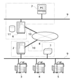
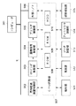
図1は本発明の実施の形態に係る監視装置と管理装置とを備えるデバイス遠隔監視システムの全体構成例を示す概念図である。デバイス遠隔監視システムは、本発明に係る監視装置としての監視装置1、拠点側管理サーバ2、デバイス3、4、5、本発明に係る管理装置としてのセンタ側管理サーバ6、センタ側クライアントPC7、通信回線8、LAN(Local Area Network)9から構成されている。図中10は通信プロトコルである。
FIG. 1 is a conceptual diagram showing an overall configuration example of a device remote monitoring system including a monitoring device and a management device according to an embodiment of the present invention. The device remote monitoring system includes a
デバイス遠隔監視システムには、デバイス3〜5の監視を統括するセンタ側として少なくとも一般的な情報処理装置が備える構成を有するセンタ側管理サーバ6が存在し、更に、情報を蓄積するためのデータベース11と、センタ側管理サーバ6にLAN9で接続され且つ単独で或いはセンタ側管理サーバ6のクライアントとして動作可能なセンタ側クライアントPC7とが存在する。センタ側管理サーバ6と拠点側管理サーバ2とは、インターネット等の通信回線8を介し、所定の通信プロトコル10で通信可能となっている。本実施の形態では、拠点側管理サーバ2やセンタ側管理サーバ6への不正アクセスを防止するためと、デバイス遠隔監視システムのネットワークにおけるファイアウォールを越す(通過する)ために、一般的なプロトコル(SMTP(Simple Mail Transfer Protocol))や認証機能も設けられている。尚、本例実施の形態では、センタ側管理サーバ6を1つしか図示していないが、後述する障害監視、カウンタ情報収集など目的に応じセンタ側管理サーバ6を複数存在させる構成も想定している。
In the device remote monitoring system, a center
一方、デバイス遠隔監視システムには、該システムの拠点側として拠点側管理サーバ2が存在し、デバイス3、4、5や不図示のパーソナルコンピュータの情報を収集する監視装置1がLAN9に接続されている。監視装置1は、LAN9を介して通信可能な各種のデバイス3、4、5の稼動情報や障害情報を含むメンテナンス情報を収集すると共に、デバイス3、4、5の制御プログラムなどを更新するように制御する機能を備え、収集された情報を拠点側管理サーバ2を介してセンタ側管理サーバ6に転送する機能を備える。
On the other hand, in the device remote monitoring system, a base-side management server 2 exists as a base side of the system, and a
尚、監視装置1と拠点側管理サーバ2、センタ側クライアントPC7とセンタ側管理サーバ6は、互いに情報の共有を行うことができれば、本実施の形態のように別々の構成として設置してもよいし、それぞれの機能を併せ持つ単一の装置(監視装置1の機能と拠点側管理サーバ2の機能を併せ持つ単一の装置、センタ側クライアントPC7の機能とセンタ側管理サーバ6の機能を併せ持つ単一の装置)として設置してもよい。図1に2点鎖線枠にてその様子を示す。以後、本例実施の形態では監視装置1が外部のセンタ側管理サーバ6と通信を行う時は拠点側管理サーバ2を介しての通信を行うこととするが、拠点側管理サーバ2に監視装置1の機能を兼用させるようにしてもよい。以後、監視装置1とセンタ側管理サーバ6とが互いに情報の送受信を行うものとして説明する。
Note that the
また、図1では、監視装置1、拠点側管理サーバ2がそれぞれ1つしか示されていないが、実際の運用においては、複数の監視装置1、複数の拠点側管理サーバ2と、これら複数の監視装置1と複数の拠点側管理サーバ2とを一元的に管理するセンタ側管理サーバ6とを通信回線8を介し通信可能とすることで、デバイス遠隔監視システムが構築されている。
Although only one
デバイス3〜5としては、画像形成装置としてのプリンタ(電子写真方式及びインクジェット方式を含む)や、画像読取装置としてのスキャナや、画像通信装置としてのファクシミリや、画像形成装置としてのプリンタ機能及びファクシミリ機能を統合的に備えたデジタル複合機や、情報処理装置としてのパーソナルコンピュータや、情報処理装置としてのプリントサーバなどが挙げられる。尚、画像形成装置につていは後述の記載において詳しく説明することとする。更に、不図示のパーソナルコンピュータは、図7において501で示すようにLAN9に接続されており、例えば、所定のアプリケーションデータをOS(Operating System)、プリンタドライバを介してPDL(Page Description Language)データに生成し、該生成したPDLデータをデバイス3、4、5に出力させるべく送信する機能を備える。
The
そして、監視装置1は、デバイス3〜5(プリンタ、ファクシミリ、複合機等)の稼動状態やトナー残量や用紙サイズ毎の印刷枚数等の稼動情報、パーソナルコンピュータにおけるCPUの状況やメモリ使用状況や有料アプリケーション使用状況等の稼動情報、デバイス3〜5における用紙のジャム情報、パーソナルコンピュータでの再起動回数等の各種障害情報、等を少なくとも含むメンテナンス情報を収集する。
The
図2は、図1における監視装置1のハードウェア構成を示すブロック図である。監視装置1は、一般的な情報処理装置が備える構成、即ち、CPU201、バス202、RAM203、Flash(フラッシュ)ROM204に加えて、複数の各種用途のインタフェース(以下I/Fと略称)、即ち、Network(ネットワーク)I/F205,206、Serial(シリアル)I/F207、Debug(デバッグ)I/F208を備えている。
FIG. 2 is a block diagram showing a hardware configuration of the
CPU201は、各構成部品203〜208を個別に又は総統合的に制御するものであり、フラッシュROM204に格納されたプログラムに基づき後述の図3〜図6、図9、図15〜図16のフローチャートに示す処理を実行する。バス202は、図2の監視装置1を構成する部品間のデータを受け渡す共通信号路である。RAM203は、電気的に情報を記憶でき且つ書き換え可能な記憶手段である。フラッシュROM204は、電気的に情報を書き換え可能であり且つ電源が無くなっても情報を記憶可能な不揮発性記憶手段である。ネットワークI/F205、206は、ネットワーク経由で外部と情報交換を行うインタフェースである。シリアルI/F207は、RS232Cシリアル通信にて情報交換を行うインタフェースである。デバッグI/F208は、デバッグ用途に用いるシリアル通信部であるところのインタフェースである。
The
尚、監視装置1にはキーボード等の入力デバイス、表示部、表示制御部などを備えるようにしてもよいが、後述するように監視装置1のネットワークI/F205、206に例えばサービスマンが所持するPCを接続し、該PC側から監視装置1内の設定プログラムを起動することで監視装置1の設定変更を行うことが可能である。これにより、監視装置1に入力デバイス、表示部、表示部制御部を備えなくともよいようにすることで安価に監視装置1を構築可能としている。
Note that the
また、拠点側管理サーバ2、パーソナルコンピュータ(不図示)、センタ側管理サーバ6、センタ側クライアントPC7については、一般的な情報処理装置が備える構成を備えていればよいので、詳しい説明は省略する。
The base-side management server 2, personal computer (not shown), center-
図3は、図1における監視装置1が実行する障害情報確認処理のフローチャートである。図4は、図1における監視装置1が実行する応答確認処理のフローチャートである。監視装置1から拠点側管理サーバ2或いはセンタ側管理サーバ6(以下ホスト6(以下、全文修正済み)と称する)或いはセンタ側クライアントPC7に対する情報送信は上記SMTP(Simple Mail Transfer Protocol)で行い、情報受信はPOP(Post Office Protocol)により行う場合について図3の障害情報確認処理、及び図4の応答確認処理を説明する。
FIG. 3 is a flowchart of the failure information confirmation processing executed by the
図3において、監視装置1は監視対象のデバイス3〜5の障害情報を確認する障害情報確認プログラムを起動し、監視対象のデバイス3〜5それぞれに関し、以下のステップS301〜ステップS305の処理を行うことにより、例えば1分間隔で障害情報確認処理を行っている。先ずステップS301において、監視装置1はLAN9を介して監視対象のデバイス3〜5に対し障害情報を取得しに行く。次にステップS302において、上記ステップS301で障害情報を取得したかどうかを判定し、障害情報を取得したと判断した場合はステップS303に進む。
In FIG. 3, the
ステップS303において、監視装置1はホスト6に対し、上記ステップS302において取得した障害情報を送信する。次にステップS304において、監視装置1はホスト6からの応答を待つ応答確認処理(図4)を実行する。一方、ステップS302において、障害情報を取得しなかったと判断した場合は、ステップS305に進み、監視装置1は1分間隔で障害情報の確認を行うために、1分間待機し、その後ステップS301に戻る。
In step S303, the
図4において、監視装置1は図3におけるステップS303でホスト6へ障害情報を送信した後、ステップS304で起動される応答確認処理を実行する。本処理は、監視装置1から障害情報をホスト6が受け取った場合、受け取ったことを示す情報をホスト6から監視装置1宛に電子メール(以下メールと略称)で通知するものである。応答確認処理においては、監視装置1は以下のステップS308〜ステップS310の処理を例えば30秒間隔で繰り返しながら、最高30分間ホスト6からの応答を待ち、その間に応答がなければホスト6に対し1回のみ障害情報の再送処理を行う。
4, after transmitting the failure information to the
ステップS308では、監視装置1は上記30秒間隔で処理を行うための30秒待機を行う。次にステップS309において、監視装置1はホスト6からのメールを受信し、ステップS310において、受信したメールが障害情報受信を示す応答メールかどうかをチェックする。ステップS310において、受信したメールの内容が応答メールであると判断した場合は、本応答確認処理を終了する。一方、ステップS310において、応答メールでないと判断した場合は、本応答確認プログラムが起動されてから30分以内であればステップS308に戻り、本応答確認プログラムが起動されてから30分を超えた場合はステップS311に進む。
In step S308, the
ステップS311において、監視装置1はホスト6に対する障害情報の送信回数が1回であるか否かを判別し、障害情報の送信の回数が1回ではない場合、即ち、既にホスト6に障害情報の再送を行っていた場合には、処理を終了する。一方、ステップS311において、障害情報の送信回数が1回である場合、即ち、まだ1回もホスト6に障害情報を再送していない場合は、ステップS312において、監視装置1は障害情報をホスト6へ再送する。これにより、障害情報の再送は1回のみ行われることになる。
In step S311, the
図5は、図1における監視装置1がデバイス3〜5やパーソナルコンピュータのカウンタ情報を取得するカウンタ情報取得処理のフローチャートであり、図6は、図1における監視装置1がデバイス3〜5やパーソナルコンピュータのカウンタ情報をホスト6に送信するカウンタ情報送信処理を示すフローチャートである。本実施の形態でのカウンタ情報とは、デバイス3〜5やパーソナルコンピュータの上記メンテナンス情報の一部或いは全てを含む情報であり、図5,6の処理は各デバイスのそれぞれに対して実行される。
FIG. 5 is a flowchart of a counter information acquisition process in which the
図5において、監視装置1はカウンタ情報を取得するカウンタ情報取得プログラムを起動し、監視対象のデバイス3〜5それぞれに関し、以下のステップS401〜ステップS403の処理を例えば60分間隔で行うことによりホスト6からのカウンタ情報の取得要求に備えている。先ずステップS401において、監視装置1は各デバイスからカウンタ情報を取得する。次にステップS402において、監視装置1は上記ステップS401で各デバイスから取得したカウンタ情報を、ホスト6からのカウンタ情報要求に備えフラッシュROM204に保存する。ここで、各デバイスから取得するカウンタ情報のデータ形式とホスト6へ送信するカウンタ情報のデータ形式が異なる場合には、このカウンタ情報の保存の時点でデータ変換しておくことも可能である。また、このデータ変換をホスト6からカウンタ情報要求があった時点で行う方法もある。次にステップS403において、監視装置1は60分後に同様のカウンタ情報の取得処理を行うために、60分待機し、その後ステップS401に戻る。
In FIG. 5, the
図6において、監視装置1はホスト6からのカウンタ情報の要求に対しカウンタ情報を送るためにカウンタ情報送信プログラムを起動する。ホスト6は監視装置1に対してカウンタ情報要求コマンドを含むメールを送信することで、カウンタ情報を要求する。本カウンタ情報送信処理は、例えば3分間隔でホスト6からのメールをチェックし、カウンタ情報の要求に備える。先ずステップS405において、監視装置1はホスト6からのカウンタ情報の要求の有無をチェックする。次いでステップS406において、カウンタ情報の要求があるか否かを判別し、要求がないしと判断した場合は、ステップS410へ進む。一方、ステップS406において、カウンタ情報の要求ありと判断した場合は、ステップS407に進む。
In FIG. 6, the
ステップS407においては、監視装置1は上述の図5のカウンタ情報取得処理によりカウンタ情報を保存しているかどうかを判断する。カウンタ情報が保存されている場合は、ステップS408において、監視装置1は保存してあるカウンタ情報をホスト6へ送信する。本処理が実行されることにより監視装置1からホスト6に送信されたカウンタ情報は、上記で説明したようにセンタ側クライアントPC7において共有され、例えばオペレータによる参照が可能となっている。一方、カウンタ情報が保存されていない場合は、監視装置1はカウンタ情報が未収集である旨をホスト6へ通知する。ステップS410では、監視装置1は例えば3分間隔でホスト6からのカウンタ情報の要求をチェックするため3分待機する。
In step S407, the
このように、図3の障害情報確認処理、図4の応答確認処理、図5のカウンタ情報所得処置、及び図6のカウンタ情報送信処理が実行されることにより、ユーザに利用される画像形成装置やパーソナルコンピュータなどのデバイスにおけるメンテナンス情報を遠隔から一元的に集中管理することができる。 As described above, the failure information confirmation processing of FIG. 3, the response confirmation processing of FIG. 4, the counter information acquisition processing of FIG. 5, and the counter information transmission processing of FIG. And centralized management of maintenance information in devices such as personal computers and remote devices.
図7は上記図1におけるデバイス3〜5の一例である画像形成装置の全体を制御するコントローラの構成例を示すブロック図である。画像形成装置のコントローラは、原稿給送装置制御部502、イメージリーダ制御部503、画像信号制御部504、プリンタ制御部505、外部I/F506、CPU回路部507、ソータ制御部513、フィニッシャ制御部514、状態検知部515を備えている。図7において、511は画像形成装置の操作部、512は画像形成装置の表示部、501は画像形成装置にLAN9を介して接続されたコンピュータである。
FIG. 7 is a block diagram showing a configuration example of a controller that controls the entire image forming apparatus as an example of the
CPU回路部507は、CPU(図示略)、RAM508、ROM509、ハードディスク(HDD)510を備えている。CPUは、ROM508に格納されている制御プログラムに基づき、原稿給送装置制御部502、イメージリーダ制御部503、画像信号制御部504、プリンタ制御部505、外部I/F506、操作部511、表示部512、ソータ制御部513、フィニッシャ制御部514、状態検知部515を制御する。ROM508は、制御プログラムを格納する。RAM509は、制御データを一時的に保持し、また制御に伴う演算処理の作業領域として用いられる。ハードディスク510は、制御プログラムに必要な情報や、原稿給送装置制御部502〜状態検知部515から受信した情報を記憶する。
The
原稿給送装置制御部502は、原稿積載部にセットされた原稿を原稿読取位置へ自動的に給送する原稿給送装置(図示略)をCPU回路部507からの指示に基づき駆動制御する。イメージリーダ制御部503は、原稿を走査するスキャナユニット(図示略)、原稿の光学像を電気信号に光電変換するイメージセンサ(図示略)などに対する駆動制御を行い、イメージセンサから出力されたアナログ画像信号を画像信号制御部504に転送する。画像信号制御部504は、アナログ画像信号をデジタル信号に変換した後に各処理を施し、このデジタル信号をビデオ信号に変換してプリンタ制御部505に出力する。画像信号制御部504による処理動作は、CPU回路部507により制御される。
The document
外部I/F506は、LAN9及び不図示のLANインタフェースを介してコンピュータ501から入力されたデジタル画像信号に各種処理を施し、このデジタル画像信号をビデオ信号に変換してプリンタ制御部505に出力する。また、外部I/F506は、LAN9及びLANインタフェースを介して監視装置1と通信を行う。プリンタ制御部505は、入力されたビデオ信号に基づき、感光体に対する露光を制御する露光制御部(図示略)を駆動する。操作部511は、画像形成に関する各種機能を設定する複数のキー、設定状態を示す情報を表示するための表示部などを有し、各キーの操作に対応するキー信号をCPU回路部507に出力すると共に、CPU回路部507からの信号に基づき対応する情報を表示部512に表示する。
The external I /
ソータ制御部513は、画像形成が完了した用紙を仕分けるソータ機構(図示略)を駆動制御する。フィニッシャ制御部514は、画像形成が完了した用紙の後処理(用紙に穴を開けるパンチ処理、用紙を綴じるステイプル処理など)を行うフィニッシャ機構(図示略)を駆動制御する。ソータ制御部513、フィニッシャ制御部514は、外部I/F506を経由したユーザからの入力または操作部511からの設定により、CPU回路部507からの信号に基づき動作する。状態検知部515は、図示の各ブロックからの状態情報を収集し、異常検知等の検知及び検知結果に基づく判断を行い、判断結果をCPU回路部507に通知する。CPU回路部507は、この通知に従い表示部512に異常を表示し、外部I/F506を経由してコンピュータ501等へ異常を通知する。
The
図8は、図7の画像形成装置のソフトウェア構成を示すブロック図である。画像形成装置は、タスクマネージャA−101、紙搬送部タスク群A−102、シーケンス制御タスクA−103、通信タスクA−104、管理用データ作成タスクA−105、状態監視タスクA−106を備えている。 FIG. 8 is a block diagram showing a software configuration of the image forming apparatus of FIG. The image forming apparatus includes a task manager A-101, a paper transport unit task group A-102, a sequence control task A-103, a communication task A-104, a management data creation task A-105, and a state monitoring task A-106. ing.
タスクマネージャA−101は、複数のタスクを同時に管理するためのものである。紙搬送部タスク群A−102は、原稿及び画像形成される用紙の搬送を司るタスク群である。シーケンス制御タスクA−103は、画像形成装置全体の管理を行うタスクである。通信タスクA−104は、監視装置1と通信を行うためのタスクである。
The task manager A-101 is for managing a plurality of tasks simultaneously. The paper transport unit task group A-102 is a task group that manages the transport of a document and a sheet on which an image is formed. The sequence control task A-103 is a task for managing the entire image forming apparatus. The communication task A-104 is a task for communicating with the
管理用データ作成タスクA−105は、本実施の形態の遠隔管理用データを作成するためのタスクである。画像形成装置では、画像形成処理ごとに用紙サイズ別、処理モード別、用紙種別、白黒/カラー別の稼動情報のカウントを行っている。これらの稼動情報のカウントは管理用データ作成タスクA−105にて行われ、画像形成装置内のハードディスク510に格納されている。同様にして、ジャム、エラー、アラームなどのステータス情報(障害情報)が所定のデータフォーマットで画像形成装置内のハードディスク510に格納される。更に、画像形成装置内の各部ごとに、消耗部品の交換寿命と、消耗部品の使用度数を表したカウンタ(部品カウンタ)を持っており、管理用データ作成タスクA−105の中でカウントされた結果が画像形成装置のハードディスク510に格納される。
The management data creation task A-105 is a task for creating the remote management data of the present embodiment. The image forming apparatus counts the operation information for each sheet size, each processing mode, each sheet type, and each black and white / color for each image forming process. The operation information is counted by the management data creation task A-105, and is stored in the
状態監視タスクA−106は、画像形成装置内の異常(ジャム、エラー、アラーム)を検知するか、予め設定されたデバイスのステータス変化を検知するタスクであり、検知に伴いステータス情報が所定のデータフォーマットで画像形成装置内のハードディスク510に格納される。
The status monitoring task A-106 is a task for detecting an abnormality (jam, error, alarm) in the image forming apparatus or detecting a change in the status of a preset device. The data is stored in a format on the
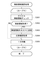
図9は、図1における監視装置1においてホスト6からの指令を含むメールを受け取り、指示に従った処理を行うためのメール受信処理のフローチャートである。本メール受信処理は、スケジューリングされていると共に定期的に実行されるものであり、ホスト6から送信されるメールを一通受信するか、或いはメールを全て受信し終えることにより終了する。
FIG. 9 is a flowchart of a mail receiving process in which the
先ずステップS701では、監視装置1はメールサーバ上にメールが到着しているかどうかを確認する。ステップS701において、メールサーバ上にメールが到着していない場合は、本メール受信処理を終了する。ステップS701において、メールサーバ上にメールが到着していた場合は、ステップS702において、監視装置1はメールサーバからメール一通のみを受信してくる。次にステップS703において、監視装置1は受信したメールがホスト6からのメールかどうかを判定する。本実施の形態においては、監視装置1側でホスト6のメールアドレスを認識しているため、送信元のメールアドレスがホスト6のメールアドレスか否かによって、受信したメールがホスト6からのメールか否かの判定を行っている。
First, in step S701, the
ステップS703において、上記受信したメールがホスト6からのメールではないと判断した場合は、監視装置1はそのメールはゴミメールであると判断して破棄し、上記ステップS701に戻り、次のメールを受信する。ステップS703において、上記受信したメールがホスト6からのメールであると判断した場合は、監視装置1はメールを解読することによりホスト6の指令(要求)を解釈し、ステップS704において、その指令に相応しい処理プログラムを起動し、本メール受信プログラムを終了する。
If it is determined in step S703 that the received mail is not a mail from the
本実施の形態において、後述する、モジュールアップデート処理、バージョン情報取得処理もホスト6からのメールによる指示により行われ、本メール受信プログラムによってメールを受け取り、それぞれアップデートコマンド処理プログラム(図11)、バージョン収集処理プログラム(図12)を起動して、モジュールアップデート処理、バージョン情報取得処理を実行する。また、図9のメール受信処理は後述する図11や図12の処理を実行させるためのみに行なわれるものに限定されるものではなく、この処理により、HTTPやFTPに比べ、監視装置1を宛先とする電子メールは、監視装置1が設置されているユーザ環境に受信され易く、様々な指示をホスト6から容易に行なえるという効果を得ることが出来る。つまり、ユーザ側に設置された監視装置1へHTTPやFTPによりアクセスしようとしても、セキュリティーの関係から外部からのアクセスは禁止され不都合を生じることがあるが、これを未然に防ぐことができる。
In the present embodiment, module update processing and version information acquisition processing, which will be described later, are also performed according to an instruction from the
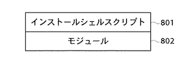
図10はホスト6から送信されるモジュールアップデート指示コマンドメール(電子メール)に添付されるデータの形式を示す図である。該モジュールアップデート指示コマンドメールは、監視装置1が作動するモジュールのアップデートを指示するためのものである。本データは、インストールシェルスクリプト801と、アップデートするモジュール(本体)802とから構成されており、圧縮、暗号化され、モジュールアップデート指示コマンドメールに添付される。インストールシェルスクリプト801は、監視装置1上のオペレーションシステムで実行可能なコマンドが、条件付きの起動制御なども含め一つ以上記載されたものであり、監視装置1の記憶部にファイルとして格納され、該格納されたそのファイルが監視装置1により実行される。
FIG. 10 is a diagram showing a format of data attached to a module update instruction command mail (e-mail) transmitted from the
インストールシェルスクリプト801内には、常駐モジュールの停止、アップデートモジュールの停止などインストールの前処理用のコマンドと、モジュール802を監視装置1内に格納するためのコピーコマンドと、アップデート後の再起動などの後処理用コマンドが記載されている。尚、インストールシェルスクリプト801の内容は、アップデートするモジュール802の性格(常駐、非常駐、共有ライブラリなど)により異なる。
The installation shell script 801 includes commands for pre-installation processing, such as stopping a resident module and stopping an update module, a copy command for storing the
例えば、必要なときにのみ起動される非常駐プログラムであるバージョン取得プログラム(図12で後述)は、アップデート対象モジュールが起動されていないタイミングで(本実施の形態では、アップデート対象モジューが起動中はモジュールの更新処理がエラーとなるため、成功するまで更新処理を再試行する)アップデート対象モジュールのアップデートが可能であり、起動されていないアップデート対象モジュールは、次回必要な時に起動される際には、既にアップデートされており、アップデートされたモジュールの起動後、更にこのアップデートされたモジュールの再起動(後処理)は不要である。 For example, a version acquisition program (described later with reference to FIG. 12), which is a non-resident program that is started only when necessary, is executed at a timing when the module to be updated is not started (in the present embodiment, the module is running while the module to be updated is running). (The retry process will be repeated until it succeeds.) The update target module can be updated, and the non-started update target module will be After the updated module is started, it is not necessary to restart (post-process) the updated module.
また、ソフトウェアモジュールのアップデートにもともない、共有メモリ(Flash(フラッシュ)ROM204)上のデータが不要になり破棄をしたい場合や、所定のモジュールのアップデートが行なわれ、モジュール稼動の安定性を重視するような場合に、後処理として再起動が必要になる。 Further, when the data on the shared memory (flash (flash) ROM 204) becomes unnecessary due to the update of the software module and the data is to be discarded, or when a predetermined module is updated, the stability of the module operation is emphasized. In such a case, a restart is required as post-processing.
図11は、図9のメール受信処理におけるコマンド処理プログラムの起動に応じて実行されるコマンド処理としてのアップデートコマンド処理のフローチャートである。図11のアップデートコマンド処理は、上記図9に示した監視装置1のメール受信処理において、ホスト6からモジュールアップデート指示を含むメールを受け取り(ステップS703でYES)、受信したメールがアップデート指示と解釈された場合に、ステップS704で起動される。
FIG. 11 is a flowchart of an update command process as a command process executed in response to the activation of the command processing program in the mail receiving process of FIG. In the update command processing of FIG. 11, in the mail reception processing of the
ステップS901において、監視装置1はホスト6から受信したメールの添付ファイルをRAM203上で復号化及び解凍し、上記図10に示したインストールシェルスクリプト801及びモジュール802から構成されるデータを取り出す。次にステップS902において、監視装置1はインストールシェルスクリプト801を起動し、モジュール802をインストールする(即ち、監視装置1で動作中のモジュールをモジュール802にアップデートする)。常駐モジュールとしては、例えば、デバイスエラー監視モジュールや、常駐モジュールのハングアップを監視するモジュールが挙げられる。そして、ステップS902においてインストールされたインストールシェルスクリプト801に基づきアップデート対象となる夫々の常駐及び非常駐モジュールの動作を停止するとともに、その後に、アップデート対象モジュール(図8の802)の置き換えが行なわれる。
In step S901, the
このモジュールのアップデート処理についてもう少し詳しく説明すると、例えば、監視装置1内で、印刷枚数のカウンタ情報を収集し或いは通知するなどの印刷に対する課金にかかわる課金処理が動作している場合に、この課金処理動作をしているモジュールのアップデートを即座に行なうことは、課金処理に重大な支障をきたしてしまう恐れがある。そこで、このような課金処理などの重要処理にかかわるモジュールのアップデートを行なう場合には、モジュールの動作が終了するまで待機するようにして、モジュールの動作終了後にアップデート処理を行なうようにすればよい。
The update process of this module will be described in more detail. For example, when a charging process related to printing such as collecting or notifying the counter information of the number of printed sheets is operating in the
また、別の例としては監視装置1の所定のタイミングにおける再起動直後に、監視装置1がアップデート対象となるモジュールのアップデートを行なうようにする処理コマンドを、インストールシェルスクリプト801に記載しても良い。
Further, as another example, a processing command for causing the
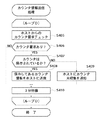
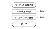
図12は、図9のメール受信処理におけるコマンド処理プログラムの起動に応じて実行されるコマンド処理としてのバージョン収集処理のフローチャートであり、このバージョン収集処理は、上記図9に示した監視装置1のメール受信処理において、ホスト6からバージョン情報取得指示を含むメールを受け取ったと判別した場合に(ステップS703)、ステップS704で起動される。
FIG. 12 is a flowchart of a version collection process as a command process executed in response to the activation of the command processing program in the mail reception process of FIG. 9, and the version collection process is performed by the
ステップS1001において、監視装置1は監視装置1内に格納されている各モジュール(プログラム、シェルスクリプト、ライブラリなど)個別のバージョン情報及び監視装置1全体としてのバージョン情報を収集(“Software Version")し、ホスト6に対する返信データを生成する。本実施の形態において、返信データはテキスト形式であり、印刷すると図13に示す形式となる。次にステップS1002において、監視装置1は上記ステップS1001で生成したバージョン情報をファイルとしてメールに添付し、ホスト6へ送信する。
In step S1001, the
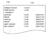
図13は上記図12のバージョン収集処理により生成したバージョン情報の印刷例を示す図である。図中1102で示す列に、1101で示す列の項目またはモジュールのバージョンが記載される。尚、バージョンの表記は、全項目共通フォーマット部分(例えば、”Software Version”では1.0.00まで)と、それに続く自由記述部分(右側列)から構成される。本実施の形態におけるモジュールアップデート処理においては、後述するように自動的にアップデートの成否を判断するが、その際、モジュール個別のバージョンは判断材料とせず、先頭行に“Software Version"で示すソフトウェアバージョンの値のみを判断材料とする。 FIG. 13 is a diagram showing a print example of version information generated by the version collection process of FIG. In the column denoted by 1102 in the figure, the item or module version in the column denoted by 1101 is described. The notation of the version is composed of a common format part for all items (for example, up to 1.0.00 for "Software Version"), and a free description part (right column) that follows. In the module update process according to the present embodiment, the success or failure of the update is automatically determined as described later. In this case, the version of each module is not used as a determination factor, and the software version indicated by “Software Version” is included in the first line. Only the value of is used as a judgment material.
具体的には、図13における列1101の個別のモジュールのバージョンアップが全て正常に終了した場合に、これらのバージョンアップされた個別のモジュールのバージョンを示すバージョン情報が監視装置1で保持され、ステップ1001において、これらのバージョン情報が収集されて、ソフトウェアバージョンが更新される。つまり、S1002においてホスト6に返信されるメール中のバージョン情報が最新のものであれば、正常にソフトウェアモジュールのアップデートが行なわれたことを意味する。
Specifically, when the upgrade of the individual modules in the
また、ソフトウェアバージョンは、図13における列1101に示される様々なモジュールの組合せを示すものであり、このソフトウェアバージョンにより、夫々のモジュールのバージョンを比較することなく、監視装置1におけるソフトウェアのアップデートの成否を確認することができる。
The software version indicates a combination of various modules shown in a
バージョン情報を監視装置1からホスト6へ通知する方法として、例えば、図10に示されるインストールシェルスクリプト801に、監視装置1がモジュールの更新後にホスト6宛てに自発的に更新後のバージョン情報をイベント通知される処理を行なわせるコマンドを記載しても良いが、ホスト6が、モジュールのアップデートの成否をも監視装置1から受信する電子メールを利用して確認するようにすれば、監視装置1から自発的にホスト6にコネクションを張り成否を通知してくるような形態にくらべて、そのコネクションを張る必要もなくホスト6の処理負荷をより一層軽減することができる。
As a method of notifying the version information from the
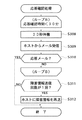
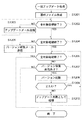
図14はホスト6を含むホスト6側主導で行われる、ホスト6の管理下の単数或いは複数の監視装置1のモジュールを一括アップデートする一括アップデート処理のフローチャートである。また、図15は、図14における一括アップデート処理を行う目的で、ホスト6に接続したセンタ側クライアントPC7上で動作する一括アップデートプログラムにおけるアップロード処理開始前のセンタ側クライアントPC7の画面を示す図である。
FIG. 14 is a flowchart of a collective update process performed by the
Window1301には、アップデート対象とするモジュールを有する、ホスト6管理下の監視装置1を一覧表示する。図中では詳細に記載していないが、ホスト6管理下の全ての監視装置1に対して同じアップデートを行わない場合に備え、アップデート処理対象の監視装置1を上記一覧に追加又は上記一覧から削除する機能もある。1302は、各監視装置1の現在のソフトウェアバージョンを示している。1303は、各監視装置1から最終バージョン情報を取得した時間を示している。本実施の形態では、監視装置1を設置した後、または監視装置1に対しモジュールのアップデートを行った後、必ずバージョン情報を取得しているため、1302、1303に示すバージョン及び時刻は各監視装置1の最新の情報となっている。1304は、今回のアップデート後、各監視装置1のソフトウェアバージョンとなるべき値を示している。
The
ステップS1201において、ホスト6は上記図10で説明したモジュールアップデート用の添付ファイルを作成する。次にステップS1203において、ホスト6はアップデート処理対象とするホスト6管理下の監視装置1全てに対し、モジュールアップデート指示を含み且つ上記ステップS1201で作成したアップデート用の添付ファイルを添付したメールを送信する。ステップS1202において、ホスト6は全アップデート処理対象の監視装置1に対しステップS1203の処理をし終えたかどうかを判断している。
In step S1201, the
次にステップS1205において、ホスト6はアップデート処理対象とするホスト6管理下の監視装置1全てに対し、バージョン情報取得指示を含むメールを送信する。ステップS1204において、ホスト6は全アップデート処理対象の監視装置1に対しステップS1205の処理をし終えたかどうかを判断している。尚、本バージョン情報取得処理はアップデート処理後の各監視装置1の状態を得るための処理である。そのため、各監視装置1がアップデート指示メールを受け取りアップデート処理を完了する十分な時間をおいて、本バージョン情報取得処理を行わなければならない。この十分な時間は、アップデートの前処理と後処理の違いのため、モジュールにより異なる。
Next, in step S1205, the
図10で説明したように、アップデートされたモージュールの再起動などの後処理があり、実測上把握されている再起動時間が10分である場合、10分以上の時間をおいた後、ホスト6から本バージョン取得メールが監視装置1に発せられる。このバージョン取得メールを送るまでにホスト6側で待機する時間は、アップデートモジュールのバージョンに対応するものであり、つまり、所定のバージョンにおけるアップデートモジュールの内容に、どのような処理(後処理、前処理)が含まれるかにより異なる。図15、図16に様々な監視装置1における様々なバージョンがホスト6に管理されているが、各監視装置1のアップデートを行なう場合に、そのバージョンによってホスト6は異なる時間を採用する。
As described with reference to FIG. 10, when there is a post-process such as a restart of the updated module and the restart time that is actually measured is 10 minutes, the host waits for 10 minutes or more and then restarts. 6, the version acquisition mail is issued to the
次にステップS1206〜ステップS1210において、ホスト6は各監視装置1におけるモジュールのアップデート処理の成否の確認を行う。即ち、ステップS1206では、ホスト6は全アップデート処理対象の監視装置1に対しステップS1207〜ステップS1210の処理を行ったかどうかを判断している。ステップS1207において、上記ステップS1205で送信したバージョン情報取得要求に対する返事がなかった場合は、アップデート成否の判断ができないため、アップデート処理は失敗とみなし、ステップS1210に進む。ステップS1207において、上記ステップS1205で送信したバージョン情報取得要求に対する返事が得られていた場合は、ステップS1208に進む。
Next, in steps S1206 to S1210, the
ステップS1208において、ホスト6は取得した情報内のソフトウェアバージョン(図13に示す"Software Version")の値とアップデート処理後に、全アップデート処理対象の監視装置1がとるべきソフトウェアバージョン1304(図15)とを比較する。ステップS1209において、上記ステップS1208の比較の結果、正しくアップデートされていると判断した場合は、ステップS1206に戻り、ホスト6は他の処理対象の監視装置1についてステップS1207〜S1210の処理をする。ステップS1209において、上記ステップS1208の比較の結果、正しくアップデートされていないと判断した場合は、ステップS1210に進む。ステップS1210においては、アップデート失敗の場合の処理として、ホスト6はアップデート失敗した監視装置1を識別する情報を記憶する。
In step S1208, the
図16は上記図15で示したセンタ側クライアントPC7上の画面の、全アップデート処理対象の監視装置1に対して上記図14の処理を行った後の状態を示す画面である。Window1401上において、1402はステップS1205で得たアップデート後のバージョンを示し、1403はステップS1205によりバージョン情報を取得した時刻を示している。アップロード失敗と判断されステップS1210の処理を行った監視装置1には、1405で示す欄にチェックを表示し、失敗したことを明示している。これら監視装置1は、現在のソフトウェアバージョン1402と、アップデート後とるべきソフトウェアバージョン1404とが異なっている。
FIG. 16 is a view showing the screen of the center-
尚、本実施の形態ではアップロード失敗を図16のWindow1401上に明示しただけであったが、これに限定されるものではなく、ステップS1210で保存した情報(アップデート失敗した監視装置1を識別する情報)を元に、該当する監視装置1に対するアップデート処理を自動的に再試行することも可能である。
In the present embodiment, the upload failure is only specified on the
以上説明したように、本実施の形態によれば、監視装置1がホスト6(センタ側管理サーバ6)からモジュールアップデート指示メールを受信した場合、動作中のモジュールを受信したモジュールにアップデートし、ホスト6からバージョン情報取得要求メールを受信した場合、モジュールのバージョン情報を収集すると共に収集したバージョン情報をホスト6に返信するので、監視装置1がホスト6からの遠隔操作により監視装置1内のモジュールのアップデートを効率よく行うことが可能となる。これにより、従来のようなアップデート対象の監視装置1台ずつに対しコネクションを張りアップデート処理を行うという煩雑な作業が不要となる。
As described above, according to the present embodiment, when the
また、ホスト6は監視装置1それぞれに一括して、少なくともアップデートするモジュール及びインストールシェルスクリプトを含むモジュールアップデート指示メールを送信し、監視装置1それぞれに一括して、監視装置1内の各モジュール個別及び監視装置1全体のバージョン情報の取得を要求するバージョン情報取得要求メールを送信し、監視装置1それぞれから取得要求の返信としてバージョン情報をメールで受信するので、ホスト6が管理下に置く複数の監視装置1の装置内のモジュールを、遠隔操作により一括してアップデートすることが可能となる。これにより、従来のようなアップデート対象の監視装置1台ずつに対しコネクションを張りアップデート処理を行うという膨大な作業が不要となる。
The
また、ホスト6はモジュールのアップデートの指示を実行後、バージョン情報の取得要求及びバージョン情報の取得を実行し、アップデート後にとるべきバージョンと取得したバージョン情報とを比較し、モジュールのアップデート処理の成否を確認するので、遠隔操作による管理下にある監視装置1の装置内のモジュールアップデートの成否を自動的に判定することが可能となる。これにより、監視装置1におけるアップデートの状況を的確に管理することが可能となる。
After executing the module update instruction, the
上記本発明の実施の形態では、デバイス遠隔監視システムを図1に示す構成としたが、本発明はこれに限定されるものではなく、監視装置、センタ側管理サーバ、拠点側管理サーバ、デバイス等の設置台数、ネットワークの設置形態、監視対象とするデバイスの種類は任意とすることが可能である。 In the above-described embodiment of the present invention, the device remote monitoring system is configured as shown in FIG. 1, but the present invention is not limited to this, and the monitoring device, the center-side management server, the base-side management server, the device, etc. The number of devices installed, the network installation mode, and the types of devices to be monitored can be set arbitrarily.
また、本発明の目的は、上述した実施の形態の機能を実現するソフトウェアのプログラムコードを記録した記憶媒体を、システム或いは装置に供給し、そのシステム或いは装置のコンピュータ(またはCPUやMPU等)が記憶媒体に格納されたプログラムコードを読み出して実行することによっても達成されることはいうまでもない。 An object of the present invention is to provide a storage medium storing a program code of software for realizing the functions of the above-described embodiments to a system or an apparatus, and a computer (or a CPU or an MPU or the like) of the system or the apparatus to supply the storage medium. Needless to say, this can also be achieved by reading and executing the program code stored in the storage medium.
この場合、記憶媒体から読み出されたプログラムコード自体が前述した実施の形態の機能を実現することになり、そのプログラムコード及び該プログラムコードを記憶した記憶媒体は本発明を構成することになる。 In this case, the program code itself read from the storage medium implements the functions of the above-described embodiment, and the program code and the storage medium storing the program code constitute the present invention.
また、プログラムコードを供給するための記憶媒体としては、例えば、RAM、フロッピー(登録商標)ディスク、ハードディスク、光ディスク、光磁気ディスク、CD−ROM、CD−R、CD−RW、DVD−ROM、DVD−RAM、DVD−RW、DVD+RW、磁気テープ、不揮発性のメモリカード、ROM、EEPROM等を用いることができる。または、プログラムコードをネットワークを介してダウンロードしてもよい。 Examples of a storage medium for supplying the program code include a RAM, a floppy (registered trademark) disk, a hard disk, an optical disk, a magneto-optical disk, a CD-ROM, a CD-R, a CD-RW, a DVD-ROM, and a DVD. -RAM, DVD-RW, DVD + RW, magnetic tape, nonvolatile memory card, ROM, EEPROM, etc. can be used. Alternatively, the program code may be downloaded via a network.
また、コンピュータが読み出したプログラムコードを実行することにより、上記実施の形態の機能が実現されるだけでなく、そのプログラムコードの指示に基づき、コンピュータ上で稼動しているOS(オペレーティングシステム)等が実際の処理の一部または全部を行い、その処理によって前述した実施の形態の機能が実現される場合も含まれることはいうまでもない。 When the computer executes the readout program code, not only the functions of the above-described embodiment are realized, but also an OS (Operating System) running on the computer based on the instruction of the program code. It goes without saying that a case where some or all of the actual processing is performed and the functions of the above-described embodiments are realized by the processing is also included.
更に、記憶媒体から読み出されたプログラムコードが、コンピュータに挿入された機能拡張ボードやコンピュータに接続された機能拡張ユニットに備わるメモリに書き込まれた後、そのプログラムコードの指示に基づき、その機能拡張ボードや機能拡張ユニットに備わるCPU等が実際の処理の一部または全部を行い、その処理によって前述した実施の形態の機能が実現される場合も含まれることはいうまでもない。 Further, after the program code read from the storage medium is written into a memory provided in a function expansion board inserted into the computer or a function expansion unit connected to the computer, the function expansion is performed based on the instruction of the program code. It goes without saying that a CPU or the like provided in the board or the function expansion unit performs part or all of the actual processing, and the processing realizes the functions of the above-described embodiments.
以上説明したように、本発明によれば、監視装置は管理装置からアップデートするモジュールを受信した場合、作動中の監視装置内のモジュールを受信したモジュールにアップデートし、管理装置からバージョン情報の取得要求を受信した場合、バージョン情報を収集し管理装置に返信するので、監視装置が管理装置からの遠隔操作により監視装置内のモジュールのアップデートを効率よく行うことが可能となる。これにより、従来のように、管理装置がアップデート対象の監視装置1台ずつと通信可能に接続してアップデート処理を行うという膨大な作業を不要とすることができる。 As described above, according to the present invention, when the monitoring device receives a module to be updated from the management device, the monitoring device updates the module in the operating monitoring device to the received module, and issues a version information acquisition request from the management device. Is received, the version information is collected and returned to the management device, so that the monitoring device can efficiently update the module in the monitoring device by remote control from the management device. This eliminates the need for an enormous amount of work in which the management device communicably connects to each monitoring target device to be updated and performs the update process as in the related art.
1 監視装置
2 拠点側管理サーバ
3、4、5 デバイス
6 センタ側管理サーバ(指示手段、取得要求手段、取得手段、成否確認手段)
7 センタ側クライアントPC
8 通信回線
9 LAN
10 通信プロトコル
11 データベース
201 CPU(処理手段、情報収集手段)
205、206 ネットワークI/F(返信手段、受信手段)
1 monitoring device 2 base-
7 Center side client PC
8
10 communication protocol 11
205, 206 Network I / F (reply means, receiving means)
Claims (18)
前記管理装置との間で電子メールによる通信を行う電子メール手段と、
前記管理装置から電子メールにより、前記監視装置が作動する第1のモジュールをアップデートするための第2のモジュールを前記電子メール手段が受信したことに応じて自動的に作動中の前記第1のモジュールを前記受信した第2のモジュールにアップデートする処理手段と、
前記管理装置から電子メールにより前記第1のモジュールのバージョン情報の取得要求を前記電子メール手段が受信した場合、前記バージョン情報を収集する情報収集手段と、
前記情報収集手段により収集した前記バージョン情報を電子メールにより前記管理装置に返信する返信手段と、を有することを特徴とする監視装置。 A monitoring device that acquires information from at least one image forming device to be monitored by communication and can communicate with a management device,
E-mail means for performing communication by e-mail with the management device,
The first module automatically operating in response to receiving by the e-mail means a second module for updating the first module on which the monitoring device operates by e-mail from the management device; Processing means for updating to the received second module,
Information collecting means for collecting the version information when the electronic mail means receives a request for obtaining version information of the first module by electronic mail from the management apparatus;
And a reply unit for returning the version information collected by the information collection unit to the management device by e-mail.
前記処理手段は、前記受信手段により受信した前記アップデート指示電子メールに含まれる前記インストールスクリプトを起動し、作動中の前記第1のモジュールを前記受信手段により受信した前記アップデート指示電子メールに含まれる前記第2のモジュールにアップデートし、前記情報収集手段は、前記受信手段により受信した前記取得要求電子メールに応じて、前記バージョン情報を収集し、前記返信手段は、前記情報収集手段により収集した前記バージョン情報を前記管理装置に電子メールで返信することを特徴とする請求項1に記載の監視装置。 Further, from the management device, an update instruction e-mail including at least the second module and the installation script, and the version information indicating the version of each of the first modules in the monitoring device and the version of the entire monitoring device. Having a receiving means for receiving an acquisition request e-mail requesting acquisition,
The processing unit activates the installation script included in the update instruction e-mail received by the reception unit, and activates the first module that is included in the update instruction e-mail received by the reception unit. Updating to a second module, wherein the information collecting means collects the version information in response to the acquisition request e-mail received by the receiving means, and the reply means comprises the version collected by the information collecting means. The monitoring device according to claim 1, wherein information is returned to the management device by e-mail.
前記複数の監視装置それぞれに一括して前記複数の監視装置それぞれが作動する第1のモジュールの第2のモジュールへのアップデートを電子メールを用いて指示する指示手段と、
前記複数の監視装置それぞれに一括して前記第1のモジュールのバージョン情報の取得要求を電子メールにより行う取得要求手段と、
前記複数の監視装置それぞれから前記バージョン情報を前記取得要求手段の行う前記バージョン情報の取得要求のための電子メールの返信として取得する取得手段と、を有することを特徴とする管理装置。 A management device capable of placing a plurality of monitoring devices that acquire information by communication from a plurality of image forming devices to be monitored under management,
Instruction means for instructing, using an electronic mail, an update to the second module of the first module in which each of the plurality of monitoring devices operates collectively for each of the plurality of monitoring devices;
An acquisition requesting unit configured to collectively request the acquisition of version information of the first module by electronic mail to each of the plurality of monitoring devices;
Management means for obtaining, from each of the plurality of monitoring devices, the version information as a reply to an e-mail for the version information acquisition request made by the acquisition request means.
前記管理装置との間で電子メールによる通信を行う通信ステップと、
前記管理装置から電子メールにより前記監視装置が作動する第1のモジュールをアップデートするための第2のモジュールを前記通信ステップにおいて受信したことに応じて自動的に作動中の前記第1のモジュールを前記受信した第2のモジュールにアップデートする処理ステップと、
前記管理装置から電子メールにより前記第1のモジュールのバージョン情報の取得要求を前記通信ステップにおいて受信した場合、前記バージョン情報を収集する情報収集ステップと、
前記情報収集ステップにより収集した前記バージョン情報を電子メールにより前記管理装置に返信する返信ステップと、を有することを特徴とする制御方法。 A control method by a monitoring device capable of acquiring information from at least one image forming device to be monitored by communication and communicating with a management device,
A communication step of performing communication by e-mail with the management device;
Activating the first module automatically in response to receiving a second module for updating the first module on which the monitoring device operates by an e-mail from the management device in the communication step; A processing step of updating to the received second module;
An information collection step of collecting the version information when a request for obtaining version information of the first module is received in the communication step by email from the management device;
A replying step of returning the version information collected in the information collecting step to the management device by e-mail.
前記処理ステップは、前記受信ステップにおいて受信した前記アップデート指示電子メールに含まれるインストールスクリプトを起動し、作動中の前記第1のモジュールを前記受信ステップにおいて受信した前記アップデート指示メールに含まれる第2のモジュールにアップデートし、前記情報収集ステップは、前記受信ステップにより受信した前記取得要求電子メールに応じて、前記バージョン情報を収集し、前記返信ステップは、前記情報収集ステップにおいて収集した前記バージョン情報を前記管理装置に電子メールで返信することを特徴とする請求項9に記載の制御方法。 Further, a request is made from the management device to acquire an update instruction e-mail including at least the second module and an installation script, and the version information indicating a version of each module in the monitoring device and a version of the entire monitoring device. And receiving the acquisition request e-mail to perform,
The processing step starts an installation script included in the update instruction e-mail received in the receiving step, and activates the first module that is operating in a second mode included in the update instruction e-mail received in the receiving step. Updating the module, the information collecting step collects the version information in response to the acquisition request email received in the receiving step, and the reply step includes the step of collecting the version information collected in the information collecting step. 10. The control method according to claim 9, wherein a reply is sent to the management device by e-mail.
前記複数の監視装置それぞれに一括して前記複数の監視装置それぞれが作動する第1のモジュールの第2のモジュールへのアップデートを電子メールを用いて指示する指示ステップと、
前記複数の監視装置それぞれに一括して前記第1のモジュールのバージョン情報の取得要求を電子メールにより行う取得要求ステップと、
前記複数の監視装置それぞれから前記バージョン情報を前記取得要求ステップにおける前記バージョン情報の取得要求のための電子メールの返信として取得する取得ステップと、を有することを特徴とする制御方法。 A control method by a management device capable of placing a plurality of monitoring devices that obtain information by communication from a plurality of image forming devices to be monitored under management,
An instruction step of instructing an update to a second module of a first module on which each of the plurality of monitoring devices operates collectively for each of the plurality of monitoring devices using an electronic mail;
An acquisition requesting step of collectively requesting acquisition of version information of the first module by email to each of the plurality of monitoring devices;
An acquisition step of acquiring the version information from each of the plurality of monitoring devices as an electronic mail reply for the acquisition request of the version information in the acquisition request step.
前記管理装置との間で電子メールによる通信を行う通信ステップと、
前記管理装置から電子メールにより前記監視装置が作動する第1のモジュールをアップデートするための第2のモジュールを前記通信ステップにおいて受信したことに応じて自動的に作動中の前記第1のモジュールを前記受信した第2のモジュールにアップデートする処理ステップと、
前記管理装置から電子メールにより前記第1のモジュールのバージョン情報の取得要求を前記通信ステップにおいて受信した場合、前記バージョン情報を収集する情報収集ステップと、
前記情報収集ステップにより収集した前記バージョン情報を電子メールにより前記管理装置に返信する返信ステップと、を有することを特徴とするプログラム。 A program that causes a computer to execute a control method by a monitoring device capable of acquiring information by communication from at least one image forming device to be monitored and communicating with a management device, wherein the control method includes:
A communication step of performing communication by e-mail with the management device;
The first module that is automatically operating in response to receiving a second module for updating the first module on which the monitoring device operates by an e-mail from the management device in the communication step. A processing step of updating to the received second module;
An information collecting step of collecting the version information when a request for obtaining version information of the first module is received in the communication step by email from the management device;
A return step of returning the version information collected in the information collection step to the management device by e-mail.
前記複数の監視装置それぞれに一括して前記複数の監視装置それぞれが作動する第1のモジュールの第2のモジュールへのアップデートを電子メールを用いて指示する指示ステップと、
前記複数の監視装置それぞれに一括して前記第1のモジュールのバージョン情報の取得要求を電子メールにより行う取得要求ステップと、
前記複数の監視装置それぞれから前記バージョン情報を前記取得要求ステップにおける前記バージョン情報の取得要求のための電子メールの返信として取得する取得ステップと、を有することを特徴とするプログラム。 A program that causes a computer to execute a control method by a management device capable of placing a plurality of monitoring devices that acquire information by communication from a plurality of image forming devices to be monitored, and the control method includes:
An instruction step of instructing an update to a second module of a first module on which each of the plurality of monitoring devices operates collectively for each of the plurality of monitoring devices using an electronic mail;
An acquisition requesting step of collectively requesting acquisition of version information of the first module by email to each of the plurality of monitoring devices;
An acquisition step of acquiring the version information from each of the plurality of monitoring apparatuses as a reply of an e-mail for the version information acquisition request in the acquisition request step.
Priority Applications (3)
| Application Number | Priority Date | Filing Date | Title |
|---|---|---|---|
| JP2003435644A JP2004234645A (en) | 2003-01-10 | 2003-12-26 | Monitoring device of image forming apparatus, control method by the monitoring device, program for executing the control method, management device, control method by the management device, and program for executing control method |
| US10/755,032 US7882180B2 (en) | 2003-01-10 | 2004-01-09 | Monitoring apparatus for image forming apparatus, control method executed by the monitoring apparatus, program for implementing the control method, and management apparatus, control method executed by the management apparatus, and program for implementing the control method |
| CNB2004100005321A CN1312580C (en) | 2003-01-10 | 2004-01-12 | Monitoring device and managing device of image forming device, its control method and programe |
Applications Claiming Priority (2)
| Application Number | Priority Date | Filing Date | Title |
|---|---|---|---|
| JP2003005155 | 2003-01-10 | ||
| JP2003435644A JP2004234645A (en) | 2003-01-10 | 2003-12-26 | Monitoring device of image forming apparatus, control method by the monitoring device, program for executing the control method, management device, control method by the management device, and program for executing control method |
Publications (1)
| Publication Number | Publication Date |
|---|---|
| JP2004234645A true JP2004234645A (en) | 2004-08-19 |
Family
ID=32964710
Family Applications (1)
| Application Number | Title | Priority Date | Filing Date |
|---|---|---|---|
| JP2003435644A Pending JP2004234645A (en) | 2003-01-10 | 2003-12-26 | Monitoring device of image forming apparatus, control method by the monitoring device, program for executing the control method, management device, control method by the management device, and program for executing control method |
Country Status (3)
| Country | Link |
|---|---|
| US (1) | US7882180B2 (en) |
| JP (1) | JP2004234645A (en) |
| CN (1) | CN1312580C (en) |
Cited By (2)
| Publication number | Priority date | Publication date | Assignee | Title |
|---|---|---|---|---|
| JP2006072685A (en) * | 2004-09-02 | 2006-03-16 | Fujitsu Support & Service Kk | Email processing device |
| US8190791B2 (en) | 2006-09-19 | 2012-05-29 | Ricoh Company, Limited | Image forming apparatus, device managing apparatus, device managing system, status acquiring method, device managing method, and computer program |
Families Citing this family (13)
| Publication number | Priority date | Publication date | Assignee | Title |
|---|---|---|---|---|
| JP2004234645A (en) * | 2003-01-10 | 2004-08-19 | Canon Inc | Monitoring device of image forming apparatus, control method by the monitoring device, program for executing the control method, management device, control method by the management device, and program for executing control method |
| JP4266957B2 (en) * | 2005-06-03 | 2009-05-27 | キヤノン株式会社 | Centralized monitoring system and control method therefor, and host device and control method therefor |
| JP2008112341A (en) * | 2006-10-31 | 2008-05-15 | Fujitsu Ltd | Information processing system, information processing method and information processing program |
| JP4539676B2 (en) * | 2007-04-19 | 2010-09-08 | コニカミノルタビジネステクノロジーズ株式会社 | Image forming apparatus, program update system, program update method, and program update program |
| EP2259204A1 (en) | 2008-03-28 | 2010-12-08 | Panasonic Corporation | Software updating apparatus, software updating system, invalidation method, and invalidation program |
| WO2009118800A1 (en) * | 2008-03-28 | 2009-10-01 | パナソニック株式会社 | Software updating apparatus, software updating system, alteration verification method and alteration verification program |
| US20100332653A1 (en) * | 2009-06-29 | 2010-12-30 | Kabushiki Kaisha Toshiba | Image forming apparatus and image forming method |
| JP5606155B2 (en) | 2010-05-25 | 2014-10-15 | キヤノン株式会社 | Image processing apparatus, communication control method, and program |
| JP5665579B2 (en) * | 2011-02-03 | 2015-02-04 | キヤノン株式会社 | Management device, management method, and program |
| WO2012124270A1 (en) * | 2011-03-15 | 2012-09-20 | パナソニック株式会社 | Tamper monitoring system, administration device, protection control module, and sensor module |
| JP5905403B2 (en) * | 2013-01-29 | 2016-04-20 | ファナック株式会社 | Control device that sends information about machine or control device by e-mail |
| CN107357557B (en) * | 2016-05-09 | 2021-01-26 | 创新先进技术有限公司 | Information updating method and device |
| JP2018047575A (en) * | 2016-09-20 | 2018-03-29 | 富士ゼロックス株式会社 | Image formation apparatus and image formation program |
Citations (4)
| Publication number | Priority date | Publication date | Assignee | Title |
|---|---|---|---|---|
| JPH1115647A (en) * | 1997-06-26 | 1999-01-22 | Hitachi Ltd | Software maintenance method |
| JP2002073954A (en) * | 2000-08-24 | 2002-03-12 | Nec Corp | Sales promotion system and method for computer peripheral device |
| JP2002189599A (en) * | 2000-12-21 | 2002-07-05 | Mitsubishi Heavy Ind Ltd | Remote maintenance system |
| JP2002297390A (en) * | 2001-03-30 | 2002-10-11 | Matsushita Electric Ind Co Ltd | Information processor, center device, terminal equipment and remote program down loading system |
Family Cites Families (43)
| Publication number | Priority date | Publication date | Assignee | Title |
|---|---|---|---|---|
| US7428575B1 (en) * | 1998-11-17 | 2008-09-23 | Ricoh Company, Ltd. | Method and system for communicating with a device attached to a computer using electronic mail messages |
| US5835911A (en) * | 1994-02-08 | 1998-11-10 | Fujitsu Limited | Software distribution and maintenance system and method |
| US5884325A (en) * | 1996-10-09 | 1999-03-16 | Oracle Corporation | System for synchronizing shared data between computers |
| US6108492A (en) * | 1997-02-14 | 2000-08-22 | Toshiba America Information Systems | Remote monitoring system |
| US6098098A (en) * | 1997-11-14 | 2000-08-01 | Enhanced Messaging Systems, Inc. | System for managing the configuration of multiple computer devices |
| US6202207B1 (en) * | 1998-01-28 | 2001-03-13 | International Business Machines Corporation | Method and a mechanism for synchronized updating of interoperating software |
| JP3361996B2 (en) * | 1998-07-09 | 2003-01-07 | 松下電送システム株式会社 | Communication device and data download method |
| US6353926B1 (en) * | 1998-07-15 | 2002-03-05 | Microsoft Corporation | Software update notification |
| TW436734B (en) * | 1998-12-24 | 2001-05-28 | Destiny Technology Corp | Printer firmware updating method |
| JP2000322244A (en) | 1999-05-07 | 2000-11-24 | Canon Inc | System and method for version up of software |
| JP3671759B2 (en) * | 1999-08-26 | 2005-07-13 | 株式会社日立製作所 | Software distribution method and system |
| US7395324B1 (en) * | 1999-10-18 | 2008-07-01 | Wnf Consulting | Method and apparatus for maintaining a computer system |
| EP1143695A3 (en) * | 2000-03-29 | 2004-01-21 | Canon Kabushiki Kaisha | Control method for image processing apparatus connectable to computer network |
| US7343401B2 (en) * | 2000-03-31 | 2008-03-11 | Fujitsu Limited | Remote maintenance apparatus, terminal connected to the apparatus and computer readable medium for realizing the apparatus and the terminal |
| US6985949B2 (en) * | 2000-05-12 | 2006-01-10 | Shinano Kenshi Kabushiki Kaisha | Content delivery system allowing licensed member to upload contents to server and to use electronic mail for delivering URL of the contents to recipient |
| US6751794B1 (en) * | 2000-05-25 | 2004-06-15 | Everdream Corporation | Intelligent patch checker |
| JP2002046327A (en) * | 2000-08-04 | 2002-02-12 | Hitachi Koki Co Ltd | Printer control device |
| US20020040389A1 (en) * | 2000-10-03 | 2002-04-04 | Wirespring Technologies, Inc. | System and method for remotely-managed content distribution network |
| US6832373B2 (en) * | 2000-11-17 | 2004-12-14 | Bitfone Corporation | System and method for updating and distributing information |
| JP2002196915A (en) * | 2000-12-25 | 2002-07-12 | Ricoh Co Ltd | Network printing system |
| US20020087668A1 (en) * | 2000-12-29 | 2002-07-04 | San Martin Raul S. | Automatic upgrade of live network devices |
| US7707571B1 (en) * | 2001-01-05 | 2010-04-27 | New Boundary Technologies Inc. | Software distribution systems and methods using one or more channels |
| US20020129107A1 (en) * | 2001-03-12 | 2002-09-12 | Loughran Stephen A. | Method and apparatus for automatic content handling |
| US7458074B2 (en) * | 2001-03-30 | 2008-11-25 | International Business Machiens Corporation | Method and apparatus for installing and upgrading an application in a computer system |
| GB2376373B (en) * | 2001-06-04 | 2004-05-05 | Hewlett Packard Co | Method of creating a model of a system on a network |
| KR100440950B1 (en) * | 2001-06-30 | 2004-07-21 | 삼성전자주식회사 | Method for upgrading software in network environment and network device thereof |
| US7266840B2 (en) * | 2001-07-12 | 2007-09-04 | Vignette Corporation | Method and system for secure, authorized e-mail based transactions |
| US7146412B2 (en) * | 2001-08-27 | 2006-12-05 | Hewlett-Packard Development Company, L.P. | System and methods for the automatic discovery, notification and installation of firmware upgrades |
| US20030086122A1 (en) * | 2001-11-06 | 2003-05-08 | Parry Travis J. | Imaging device communication via email |
| JP4039195B2 (en) * | 2001-12-27 | 2008-01-30 | 富士ゼロックス株式会社 | Network system |
| US7065560B2 (en) * | 2002-03-12 | 2006-06-20 | Hewlett-Packard Development Company, L.P. | Verification of computer program versions based on a selected recipe from a recipe table |
| US8667104B2 (en) * | 2002-05-14 | 2014-03-04 | Hewlett-Packard Development Company, L.P. | Firmware/software upgrade alert method and apparatus |
| US6892320B1 (en) * | 2002-06-03 | 2005-05-10 | Sun Microsystems, Inc. | Method and apparatus for providing multiple-version support for highly available objects |
| JP4408033B2 (en) * | 2002-09-24 | 2010-02-03 | 株式会社リコー | Remote management system |
| US8271971B2 (en) * | 2002-11-26 | 2012-09-18 | Hewlett-Packard Development Company, L.P. | System and method for automated program updating in a remote appliance |
| JP2004234645A (en) * | 2003-01-10 | 2004-08-19 | Canon Inc | Monitoring device of image forming apparatus, control method by the monitoring device, program for executing the control method, management device, control method by the management device, and program for executing control method |
| JP4095449B2 (en) * | 2003-01-10 | 2008-06-04 | キヤノン株式会社 | Monitoring device, monitoring method, and program |
| US7511840B2 (en) * | 2003-01-30 | 2009-03-31 | Kabushiki Kaisha Toshiba | Image forming apparatus |
| US7555657B2 (en) * | 2003-03-28 | 2009-06-30 | Ricoh Company, Ltd. | Communication device, software update device, software update system, software update method, and program |
| US20040249934A1 (en) * | 2003-06-06 | 2004-12-09 | Anderson Jeff M. | Updating print server software based on update emails |
| US20050027807A1 (en) * | 2003-07-30 | 2005-02-03 | Lynda Fengler | Systems and methods for facilitating peripheral device firmware installation |
| US7624393B2 (en) * | 2003-09-18 | 2009-11-24 | International Business Machines Corporation | Computer application and methods for autonomic upgrade maintenance of computer hardware, operating systems and application software |
| US7921420B2 (en) * | 2005-04-29 | 2011-04-05 | Sharp Laboratories Of America, Inc. | Systems and methods for updating imaging device drivers on one or more computer systems |
-
2003
- 2003-12-26 JP JP2003435644A patent/JP2004234645A/en active Pending
-
2004
- 2004-01-09 US US10/755,032 patent/US7882180B2/en not_active Expired - Fee Related
- 2004-01-12 CN CNB2004100005321A patent/CN1312580C/en not_active Expired - Fee Related
Patent Citations (4)
| Publication number | Priority date | Publication date | Assignee | Title |
|---|---|---|---|---|
| JPH1115647A (en) * | 1997-06-26 | 1999-01-22 | Hitachi Ltd | Software maintenance method |
| JP2002073954A (en) * | 2000-08-24 | 2002-03-12 | Nec Corp | Sales promotion system and method for computer peripheral device |
| JP2002189599A (en) * | 2000-12-21 | 2002-07-05 | Mitsubishi Heavy Ind Ltd | Remote maintenance system |
| JP2002297390A (en) * | 2001-03-30 | 2002-10-11 | Matsushita Electric Ind Co Ltd | Information processor, center device, terminal equipment and remote program down loading system |
Cited By (2)
| Publication number | Priority date | Publication date | Assignee | Title |
|---|---|---|---|---|
| JP2006072685A (en) * | 2004-09-02 | 2006-03-16 | Fujitsu Support & Service Kk | Email processing device |
| US8190791B2 (en) | 2006-09-19 | 2012-05-29 | Ricoh Company, Limited | Image forming apparatus, device managing apparatus, device managing system, status acquiring method, device managing method, and computer program |
Also Published As
| Publication number | Publication date |
|---|---|
| CN1312580C (en) | 2007-04-25 |
| US20040205140A1 (en) | 2004-10-14 |
| US7882180B2 (en) | 2011-02-01 |
| CN1517866A (en) | 2004-08-04 |
Similar Documents
| Publication | Publication Date | Title |
|---|---|---|
| USRE42166E1 (en) | Monitoring apparatus, management method and program therefor, and management apparatus and management method and program therefor | |
| US8553264B2 (en) | Information processing including specifying a printer to execute a print process of a stored job | |
| EP2015183B1 (en) | Image-forming apparatus and information-processing method | |
| JP5328389B2 (en) | Image forming apparatus, image forming system, and image forming method | |
| US7720395B2 (en) | Management apparatus, management method, and computer-readable medium storing a computer program for acquiring maintenance information from plurality of image forming apparatuses | |
| US8400666B2 (en) | Information processing apparatus and information processing method | |
| JP2004234645A (en) | Monitoring device of image forming apparatus, control method by the monitoring device, program for executing the control method, management device, control method by the management device, and program for executing control method | |
| US9619221B2 (en) | Image forming apparatus, network system, and control method of image forming apparatus | |
| US20050162693A1 (en) | Job management apparatus and method, and control program used therewith | |
| JP4652523B2 (en) | Server apparatus, image processing apparatus, information processing method, and storage medium | |
| US10382302B2 (en) | Electronic apparatus and non-transitory computer readable recording medium suitable for acquiring status information | |
| JP5317838B2 (en) | Information processing apparatus, control method therefor, program, and storage medium | |
| JP5354666B2 (en) | Image forming system, management server, image forming apparatus, processing method thereof, and program | |
| JP2009075707A (en) | Information processor, equipment information management method for information processor, and program | |
| US9860408B2 (en) | Information processing system, information processing method, and computer program product | |
| JP3970235B2 (en) | Monitoring device, counter information management method, storage medium and program in the device | |
| JP2008182704A (en) | System and method for cloning configuration of document processing devices | |
| US7734851B2 (en) | Information processing apparatus, management apparatus, and communication method | |
| JP2006031452A (en) | Image forming apparatus, control method, control program, job management apparatus, job processing method and job management program | |
| JP4250881B2 (en) | Program executed in image processing apparatus and firmware distribution apparatus | |
| JP2009064358A (en) | Data processing apparatus and setting method for the same | |
| US7072799B2 (en) | Information processing apparatus, maintenance managing method, program, and computer-readable storing medium | |
| JP2007058568A (en) | Information processor, electronic mail processing method, monitoring method for image formation device, and image formation system | |
| JP2016177460A (en) | System and program | |
| JP2005135333A (en) | Program monitoring device, program monitoring method, program, storage medium, and information acquisition system |
Legal Events
| Date | Code | Title | Description |
|---|---|---|---|
| A977 | Report on retrieval |
Free format text: JAPANESE INTERMEDIATE CODE: A971007 Effective date: 20050613 |
|
| A131 | Notification of reasons for refusal |
Free format text: JAPANESE INTERMEDIATE CODE: A131 Effective date: 20050705 |
|
| A521 | Written amendment |
Free format text: JAPANESE INTERMEDIATE CODE: A523 Effective date: 20050905 |
|
| A02 | Decision of refusal |
Free format text: JAPANESE INTERMEDIATE CODE: A02 Effective date: 20060328 |
|
| RD03 | Notification of appointment of power of attorney |
Free format text: JAPANESE INTERMEDIATE CODE: A7423 Effective date: 20060418 |
|
| A521 | Written amendment |
Free format text: JAPANESE INTERMEDIATE CODE: A523 Effective date: 20060529 |
|
| A911 | Transfer to examiner for re-examination before appeal (zenchi) |
Free format text: JAPANESE INTERMEDIATE CODE: A911 Effective date: 20060601 |
|
| A912 | Re-examination (zenchi) completed and case transferred to appeal board |
Free format text: JAPANESE INTERMEDIATE CODE: A912 Effective date: 20060908 |
|
| RD05 | Notification of revocation of power of attorney |
Free format text: JAPANESE INTERMEDIATE CODE: A7425 Effective date: 20070626 |