JP4095449B2 - Monitoring device, monitoring method, and program - Google Patents
Monitoring device, monitoring method, and program Download PDFInfo
- Publication number
- JP4095449B2 JP4095449B2 JP2003005156A JP2003005156A JP4095449B2 JP 4095449 B2 JP4095449 B2 JP 4095449B2 JP 2003005156 A JP2003005156 A JP 2003005156A JP 2003005156 A JP2003005156 A JP 2003005156A JP 4095449 B2 JP4095449 B2 JP 4095449B2
- Authority
- JP
- Japan
- Prior art keywords
- information
- notification
- management
- confirmation information
- Prior art date
- Legal status (The legal status is an assumption and is not a legal conclusion. Google has not performed a legal analysis and makes no representation as to the accuracy of the status listed.)
- Expired - Fee Related
Links
- 238000012806 monitoring device Methods 0.000 title claims description 151
- 238000000034 method Methods 0.000 title claims description 92
- 238000012544 monitoring process Methods 0.000 title claims description 71
- 238000004891 communication Methods 0.000 claims description 111
- 238000012790 confirmation Methods 0.000 claims description 69
- 238000012423 maintenance Methods 0.000 claims description 19
- 239000012141 concentrate Substances 0.000 claims 3
- 230000005540 biological transmission Effects 0.000 description 125
- 238000012545 processing Methods 0.000 description 103
- 230000000737 periodic effect Effects 0.000 description 51
- 238000010586 diagram Methods 0.000 description 30
- 230000004044 response Effects 0.000 description 19
- 230000006870 function Effects 0.000 description 18
- 230000005856 abnormality Effects 0.000 description 17
- 238000012217 deletion Methods 0.000 description 15
- 230000037430 deletion Effects 0.000 description 15
- 230000002093 peripheral effect Effects 0.000 description 8
- 230000010365 information processing Effects 0.000 description 5
- 238000012546 transfer Methods 0.000 description 5
- 238000001514 detection method Methods 0.000 description 4
- 230000000694 effects Effects 0.000 description 3
- 239000000284 extract Substances 0.000 description 3
- 238000006243 chemical reaction Methods 0.000 description 2
- 230000015572 biosynthetic process Effects 0.000 description 1
- 238000007796 conventional method Methods 0.000 description 1
- 239000000463 material Substances 0.000 description 1
- XEBWQGVWTUSTLN-UHFFFAOYSA-M phenylmercury acetate Chemical compound CC(=O)O[Hg]C1=CC=CC=C1 XEBWQGVWTUSTLN-UHFFFAOYSA-M 0.000 description 1
- 238000012805 post-processing Methods 0.000 description 1
Images


Classifications
-
- G—PHYSICS
- G06—COMPUTING; CALCULATING OR COUNTING
- G06F—ELECTRIC DIGITAL DATA PROCESSING
- G06F11/00—Error detection; Error correction; Monitoring
- G06F11/07—Responding to the occurrence of a fault, e.g. fault tolerance
- G06F11/0703—Error or fault processing not based on redundancy, i.e. by taking additional measures to deal with the error or fault not making use of redundancy in operation, in hardware, or in data representation
- G06F11/0766—Error or fault reporting or storing
- G06F11/0784—Routing of error reports, e.g. with a specific transmission path or data flow
-
- G—PHYSICS
- G03—PHOTOGRAPHY; CINEMATOGRAPHY; ANALOGOUS TECHNIQUES USING WAVES OTHER THAN OPTICAL WAVES; ELECTROGRAPHY; HOLOGRAPHY
- G03G—ELECTROGRAPHY; ELECTROPHOTOGRAPHY; MAGNETOGRAPHY
- G03G15/00—Apparatus for electrographic processes using a charge pattern
- G03G15/50—Machine control of apparatus for electrographic processes using a charge pattern, e.g. regulating differents parts of the machine, multimode copiers, microprocessor control
- G03G15/5075—Remote control machines, e.g. by a host
-
- G—PHYSICS
- G06—COMPUTING; CALCULATING OR COUNTING
- G06F—ELECTRIC DIGITAL DATA PROCESSING
- G06F11/00—Error detection; Error correction; Monitoring
- G06F11/07—Responding to the occurrence of a fault, e.g. fault tolerance
- G06F11/0703—Error or fault processing not based on redundancy, i.e. by taking additional measures to deal with the error or fault not making use of redundancy in operation, in hardware, or in data representation
- G06F11/0706—Error or fault processing not based on redundancy, i.e. by taking additional measures to deal with the error or fault not making use of redundancy in operation, in hardware, or in data representation the processing taking place on a specific hardware platform or in a specific software environment
- G06F11/0733—Error or fault processing not based on redundancy, i.e. by taking additional measures to deal with the error or fault not making use of redundancy in operation, in hardware, or in data representation the processing taking place on a specific hardware platform or in a specific software environment in a data processing system embedded in an image processing device, e.g. printer, facsimile, scanner
-
- G—PHYSICS
- G06—COMPUTING; CALCULATING OR COUNTING
- G06F—ELECTRIC DIGITAL DATA PROCESSING
- G06F11/00—Error detection; Error correction; Monitoring
- G06F11/07—Responding to the occurrence of a fault, e.g. fault tolerance
- G06F11/0703—Error or fault processing not based on redundancy, i.e. by taking additional measures to deal with the error or fault not making use of redundancy in operation, in hardware, or in data representation
- G06F11/0706—Error or fault processing not based on redundancy, i.e. by taking additional measures to deal with the error or fault not making use of redundancy in operation, in hardware, or in data representation the processing taking place on a specific hardware platform or in a specific software environment
- G06F11/0748—Error or fault processing not based on redundancy, i.e. by taking additional measures to deal with the error or fault not making use of redundancy in operation, in hardware, or in data representation the processing taking place on a specific hardware platform or in a specific software environment in a remote unit communicating with a single-box computer node experiencing an error/fault
-
- H—ELECTRICITY
- H04—ELECTRIC COMMUNICATION TECHNIQUE
- H04L—TRANSMISSION OF DIGITAL INFORMATION, e.g. TELEGRAPHIC COMMUNICATION
- H04L41/00—Arrangements for maintenance, administration or management of data switching networks, e.g. of packet switching networks
- H04L41/06—Management of faults, events, alarms or notifications
-
- H—ELECTRICITY
- H04—ELECTRIC COMMUNICATION TECHNIQUE
- H04L—TRANSMISSION OF DIGITAL INFORMATION, e.g. TELEGRAPHIC COMMUNICATION
- H04L41/00—Arrangements for maintenance, administration or management of data switching networks, e.g. of packet switching networks
- H04L41/34—Signalling channels for network management communication
- H04L41/344—Out-of-band transfers
-
- H—ELECTRICITY
- H04—ELECTRIC COMMUNICATION TECHNIQUE
- H04L—TRANSMISSION OF DIGITAL INFORMATION, e.g. TELEGRAPHIC COMMUNICATION
- H04L43/00—Arrangements for monitoring or testing data switching networks
- H04L43/08—Monitoring or testing based on specific metrics, e.g. QoS, energy consumption or environmental parameters
- H04L43/0805—Monitoring or testing based on specific metrics, e.g. QoS, energy consumption or environmental parameters by checking availability
- H04L43/0817—Monitoring or testing based on specific metrics, e.g. QoS, energy consumption or environmental parameters by checking availability by checking functioning
-
- H—ELECTRICITY
- H04—ELECTRIC COMMUNICATION TECHNIQUE
- H04N—PICTORIAL COMMUNICATION, e.g. TELEVISION
- H04N1/00—Scanning, transmission or reproduction of documents or the like, e.g. facsimile transmission; Details thereof
- H04N1/00002—Diagnosis, testing or measuring; Detecting, analysing or monitoring not otherwise provided for
- H04N1/00026—Methods therefor
- H04N1/00042—Monitoring, i.e. observation
-
- H—ELECTRICITY
- H04—ELECTRIC COMMUNICATION TECHNIQUE
- H04N—PICTORIAL COMMUNICATION, e.g. TELEVISION
- H04N1/00—Scanning, transmission or reproduction of documents or the like, e.g. facsimile transmission; Details thereof
- H04N1/00002—Diagnosis, testing or measuring; Detecting, analysing or monitoring not otherwise provided for
- H04N1/00071—Diagnosis, testing or measuring; Detecting, analysing or monitoring not otherwise provided for characterised by the action taken
- H04N1/00074—Indicating or reporting
- H04N1/00079—Indicating or reporting remotely
-
- H—ELECTRICITY
- H04—ELECTRIC COMMUNICATION TECHNIQUE
- H04N—PICTORIAL COMMUNICATION, e.g. TELEVISION
- H04N1/00—Scanning, transmission or reproduction of documents or the like, e.g. facsimile transmission; Details thereof
- H04N1/00127—Connection or combination of a still picture apparatus with another apparatus, e.g. for storage, processing or transmission of still picture signals or of information associated with a still picture
- H04N1/00344—Connection or combination of a still picture apparatus with another apparatus, e.g. for storage, processing or transmission of still picture signals or of information associated with a still picture with a management, maintenance, service or repair apparatus
-
- H—ELECTRICITY
- H04—ELECTRIC COMMUNICATION TECHNIQUE
- H04L—TRANSMISSION OF DIGITAL INFORMATION, e.g. TELEGRAPHIC COMMUNICATION
- H04L41/00—Arrangements for maintenance, administration or management of data switching networks, e.g. of packet switching networks
- H04L41/02—Standardisation; Integration
- H04L41/0233—Object-oriented techniques, for representation of network management data, e.g. common object request broker architecture [CORBA]
-
- H—ELECTRICITY
- H04—ELECTRIC COMMUNICATION TECHNIQUE
- H04N—PICTORIAL COMMUNICATION, e.g. TELEVISION
- H04N2201/00—Indexing scheme relating to scanning, transmission or reproduction of documents or the like, and to details thereof
- H04N2201/0008—Connection or combination of a still picture apparatus with another apparatus
- H04N2201/0034—Details of the connection, e.g. connector, interface
- H04N2201/0037—Topological details of the connection
- H04N2201/0039—Connection via a network
-
- H—ELECTRICITY
- H04—ELECTRIC COMMUNICATION TECHNIQUE
- H04N—PICTORIAL COMMUNICATION, e.g. TELEVISION
- H04N2201/00—Indexing scheme relating to scanning, transmission or reproduction of documents or the like, and to details thereof
- H04N2201/0077—Types of the still picture apparatus
- H04N2201/0081—Image reader
-
- H—ELECTRICITY
- H04—ELECTRIC COMMUNICATION TECHNIQUE
- H04N—PICTORIAL COMMUNICATION, e.g. TELEVISION
- H04N2201/00—Indexing scheme relating to scanning, transmission or reproduction of documents or the like, and to details thereof
- H04N2201/0077—Types of the still picture apparatus
- H04N2201/0082—Image hardcopy reproducer
-
- H—ELECTRICITY
- H04—ELECTRIC COMMUNICATION TECHNIQUE
- H04N—PICTORIAL COMMUNICATION, e.g. TELEVISION
- H04N2201/00—Indexing scheme relating to scanning, transmission or reproduction of documents or the like, and to details thereof
- H04N2201/0077—Types of the still picture apparatus
- H04N2201/0091—Digital copier; digital 'photocopier'
-
- H—ELECTRICITY
- H04—ELECTRIC COMMUNICATION TECHNIQUE
- H04N—PICTORIAL COMMUNICATION, e.g. TELEVISION
- H04N2201/00—Indexing scheme relating to scanning, transmission or reproduction of documents or the like, and to details thereof
- H04N2201/0077—Types of the still picture apparatus
- H04N2201/0093—Facsimile machine
-
- H—ELECTRICITY
- H04—ELECTRIC COMMUNICATION TECHNIQUE
- H04N—PICTORIAL COMMUNICATION, e.g. TELEVISION
- H04N2201/00—Indexing scheme relating to scanning, transmission or reproduction of documents or the like, and to details thereof
- H04N2201/0077—Types of the still picture apparatus
- H04N2201/0094—Multifunctional device, i.e. a device capable of all of reading, reproducing, copying, facsimile transception, file transception
Landscapes
- Engineering & Computer Science (AREA)
- Theoretical Computer Science (AREA)
- Signal Processing (AREA)
- General Physics & Mathematics (AREA)
- General Engineering & Computer Science (AREA)
- Physics & Mathematics (AREA)
- Computer Networks & Wireless Communication (AREA)
- Quality & Reliability (AREA)
- Multimedia (AREA)
- General Health & Medical Sciences (AREA)
- Biomedical Technology (AREA)
- Health & Medical Sciences (AREA)
- Environmental & Geological Engineering (AREA)
- Computer Hardware Design (AREA)
- Microelectronics & Electronic Packaging (AREA)
- Computer Vision & Pattern Recognition (AREA)
- Computer And Data Communications (AREA)
- Information Transfer Between Computers (AREA)
- Debugging And Monitoring (AREA)
Description
【0001】
【発明の属する技術分野】
本発明は、監視装置及び監視方法、並びにプログラムに関し、特に、複数の監視装置を一元的に管理する管理サーバと通信可能な、複数の周辺機器の少なくともカウンタを含むメンテナンス情報を管理する監視装置及び監視方法、並びにプログラムに関する。
【0002】
【従来の技術】
従来、画像形成装置のような事務機器を含む各種コンピュータ機器を遠隔監視する方法として、コンピュータ機器が接続されたネットワーク内に監視装置を設置し、該監視装置によってネットワークを介してコンピュータ機器を監視し、該監視装置から管理サーバへ監視結果情報を転送する技術が知られている。
【0003】
また、ユーザ拠点側にて利用されている端末装置へ管理サーバから応答の要求を行い、該端末装置から応答を受けることによって管理サーバが、端末装置自体または端末装置における電話回線への発信機能が正常であると確認する技術が知られている(例えば、特許文献1参照)。
【0004】
【特許文献1】
特開平04−056560号公報
【0005】
【発明が解決しようとする課題】
しかしながら、上記の特許文献1に記載の従来の技術において、管理サーバは、応答要求の送信とその応答の受信の2回の情報転送が必要であり、しかも、監視対象装置(端末装置)が複数存在する場合、管理サーバは、その2回の情報転送をその台数分行う必要がある。
【0006】
また複数台の監視対象装置(端末装置)に対して管理サーバが応答要求を送信する際、それを一斉に行うか、または時差送信を行うが、いずれの場合でも、管理サーバでは、監視対象装置(端末装置)ごとに、応答があったか否かを判定する必要がある。
【0007】
このように、複数台の監視対象装置(端末装置)に対して監視を行う管理サーバにおける処理の負荷が非常に高いという問題があった。
【0008】
本発明はこのような問題点に鑑みてなされたものであって、複数台の監視対象装置に対して監視を行う監視装置における処理負荷を軽減した監視装置及び監視方法、並びにプログラムを提供することを目的とする。
【0009】
【課題を解決するための手段】
上記目的を達成するために、本発明に係る監視装置は、複数の監視装置を一元的に管理する管理装置と通信部を介して通信可能で且つ複数の画像形成装置の稼働情報及び障害情報をネットワークを介して取得する監視装置であって、前記複数の画像形成装置の稼動情報及び障害情報を取得し管理する管理手段と、前記管理手段に管理される前記複数の画像形成装置の稼動情報及び障害情報の前記管理装置への通知を前記通信部に行わせる第1通信制御手段と、自装置を示す識別IDを含む確認情報を作成する作成手段と、前記作成手段により作成された前記確認情報の前記管理装置への通知を定期的に前記通信部に行わせる第2通信制御手段と、前記確認情報の通知回数の履歴に基づき、前記通知回数が多い場合に通知間隔が長くなるように前記確認情報の次回の通知のタイミングに係る通知タイミング情報を設定する通知タイミング設定手段とを有し、前記作成手段は、更に前記通知タイミング情報及び前記確認情報であることを識別可能な識別子を含むように前記確認情報を作成し、前記第2通知制御手段は、前記作成手段で作成された前記タイミング情報を含む確認情報の通知を前記通信部に行わせ、前記管理装置により前記確認情報の通知の履歴に基づき管理情報として、通知タイミング情報の次回の通知のタイミングを過ぎても確認情報の通知を行わない監視装置を特定可能なリストの情報が作成され、さらに、前記確認情報は、画像形成装置の各使用度数をあらわすカウンタ値を含むメンテナンス情報を含むことを特徴とする。
【0010】
【発明の実施の形態】
以下、本発明の実施の形態を、図面を参照して説明する。
【0011】
[第1の実施の形態]
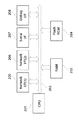
図1は、本発明に係る管理装置を含む遠隔監視システムの第1の実施の形態の全体構成を示す図である。
【0012】
本遠隔監視システムでは、センタ側管理サーバ6及び拠点側管理サーバ2が、一般的な情報処理装置によってそれぞれ構成され、インターネット等の通信回線8を介し、所定のプロトコル10によって互いに通信可能である。拠点側管理サーバ2及びセンタ側管理サーバ6は、例えばメールサーバやルータの機能を掌る部分として想定することができる。
【0013】
センタ側管理サーバ6と拠点側管理サーバ2とは、通信回線8を介して、所定のプロトコル10で接続されるが、不正アクセスを防ぐために、またファイアウォールを越すために、一般的なプロトコル(SMTP)や認証も設けるようにする。
【0014】
監視装置1が、ネットワーク9を介して画像形成装置3〜5及びパーソナルコンピュータ(以下「PC」という)12に接続され、画像形成装置3〜5及びPC12の稼動情報や障害情報(詳しくは後述)を収集すると共に、画像形成装置3〜5及びPC12の制御プログラムなどを更新する機能を備え、更に、収集した情報を、拠点側管理サーバ2を介してセンタ側管理サーバ6に転送する機能を備える。
【0015】
パーソナルコンピュータ(以下「PC」という)7がネットワークを介してセンタ側管理サーバ6に接続され、センタ側管理サーバ6のクライアントコンピュータとして動作する。PC7は各種情報処理を実行するとともに、センタ側管理サーバ6で収集された情報を共有することができる。
【0016】
なお図1では、監視装置1と拠点側管理サーバ2とが別体として設置され、またPC7とセンタ側管理サーバ6とが別体として設置されているが、監視装置1と拠点側管理サーバ2とを1つの装置にし、またPC7とセンタ側管理サーバ6とを1つの装置にしてもよい。これを、図1中において点線枠にて示す。
【0017】
なおまた、図1中には、監視装置1を1つしか図示しないが、実際には、複数の監視装置がネットワーク9に接続されるとともに、各監視装置によってそれぞれ監視される画像形成装置及びPCがネットワーク9に接続され、センタ側管理サーバ6が、それら複数の監視装置を一元的に管理する。複数の監視装置の各々が後述する各種処理/制御を実現する。
【0018】
画像形成装置3〜5は、具体的にはプリンタ(電子写真方式及びインクジェット方式を含む)、ファクシミリ装置、スキャナ、プリンタ及びファクシミリ機能が統合的に設けられたデジタル複合機、プリントサーバなどのうちのいずれかである。
【0019】
PC12は、例えば、所定のアプリケーションデータをOS(Operating System)、プリンタドライバを介してPDL(Page Description Language)データに変換し、該PDLデータを画像形成装置3〜5のいずれかに送信する機能を備える。
【0020】
なお、監視装置1は、画像形成装置3〜5及びPC12からメンテナンス情報を収集する。メンテナンス情報は、稼動情報に少なくとも障害情報を含むものであり、稼動情報は、画像形成装置3〜5では、それら装置の状態、トナー残量、用紙サイズ毎の印刷枚数等であり、PC12では、PC12内のCPU及びメモリの稼動状況、有料アプリケーション使用状況等である。障害情報は、画像形成装置3〜5でのジャム情報やPC12での再起動回数情報等である。こうしたメンテナンス情報の定義は、後述の第2及び第3の実施の形態でも適用される。
【0021】
図2は、監視装置1のハードウェア構成を示すブロック図である。監視装置1は、一般な情報処理装置が備える構成に加えて、複数の各種用途のインターフェイスを備えている。
【0022】
図中、CPU201は、監視装置1内の各構成部品を個別に及び/又は統合的に制御する。バス202では、監視装置1内の各構成部品間のデータの受け渡しが行われる。RAM203は、電気的に情報を記憶でき、かつ書き換え可能なメモリである。フラッシュROM(FlashROM)204は、電気的に書き換え可能であり、かつ電源がオフされても情報を記憶可能な不揮発性メモリである。ネットワークインターフェイス(NetworkI/F)205,206は、ネットワーク9経由で外部と情報交換を行うインターフェイスである。シリアルインターフェイス(SerialI/F)207は、RS232Cシリアル通信にて情報交換を行うインターフェイスである。デバッグインターフェイス(DebugI/F)208は、デバッグ用途に用いるシリアル通信部である。
【0023】
なお、この監視装置1に、キーボード等の入力装置、表示部、表示制御部などを備えるようにしてもよいが、ネットワークインターフェイス(NetworkI/F)205,206に、例えばサービスマンのPCを接続し、このPCによって監視装置1内の設定プログラムを起動することで、監視装置1の設定変更を行なうことができる。そのため、入力装置、表示部、表示部駆動部などを必ずしも備える必要がなく、これらを備えないことで、安価に装置を構築可能となる。
【0024】
また、拠点側管理サーバ2、PC12、センタ側管理サーバ6、PC7はそれぞれ、一般的な情報処理装置が備える構成を備えていればよいので、それらのハードウェア構成の詳しい説明は省略する。
【0025】
次に、図3及び図4を参照して、画像形成装置3〜5及びPC12に対して監視装置1によって行われる障害監視について説明する。
【0026】
図3は、監視装置1において実行される障害情報確認プログラムの処理手順を示すフローチャートである。なおここで、監視装置1から拠点側管理サーバ2、センタ側管理サーバ6、PC7への情報送信はSMTP(Simple Mail Transfer Protocol)で行い、それらからの情報受信はPOP(Post Office Protocol)で行うものとする。
【0027】
ステップS301で、監視装置1が、画像形成装置3〜5やPC12から障害情報の取得を、ネットワーク9を介して特定のプロトコルにより試みる。
【0028】
ステップS302で、ステップS301における試みの結果、障害情報を取得できたか否かを判断する。取得できた場合、ステップS303に進んで、取得した障害情報を拠点側管理サーバ2またはセンタ側管理サーバ6に送信する。取得できない場合、ステップS305に進む。
【0029】
ステップS304では、障害情報が拠点側管理サーバ2またはセンタ側管理サーバ6に正しく送信されたことを確認するために、応答確認プログラム(図4を参照して後述)を起動する。
【0030】
ステップS305で、所定時間(例えば1分)待機する。
【0031】
ステップS306で、所定時間の待機中に障害情報確認プログラム処理への終了指示があったか否かを判断し、指示があった場合は本プログラム処理を終了し、指示がない場合は、ステップS301に戻り、本プログラム処理を再度実行する。
【0032】
図4は、監視装置1において実行される応答確認プログラムの処理手順を示すフローチャートである。このプログラムは、前述のように図3のステップS304によって起動される。
【0033】
ステップS307で、監視装置1が所定時間(例えば30秒)待機する。
【0034】
ステップS308で、拠点側管理サーバ2またはセンタ側管理サーバ6から応答が返信されたことをチェックする。
【0035】
ステップS309で、ステップS308でのチェックの結果、拠点側管理サーバ2またはセンタ側管理サーバ6から応答が返信されていれば本プログラム処理を終了する。応答が返信されていなければステップS310へ進み、所定の応答確認最大時間(例えば30分)が経過したか否かを判断する。経過していなければステップS307へ戻って引き続き、応答返信チェックを行う。経過していればステップS311へ進む。
【0036】
ステップS311では、今までに障害情報を送信した回数が所定回数(例えば1回)以下であるか否かを判断する。所定回数以下である場合、すなわち例えば、今回はじめて障害情報を送信した場合はステップS312に進んで、障害情報を拠点側管理サーバ2またはセンタ側管理サーバ6に再度送信し、ステップS307に戻る。障害情報送信回数が所定回数を超えている場合は、本プログラム処理を終了する。
【0037】
次に、図5及び図6を参照して、監視装置1によって行われるカウンタ情報の収集処理について説明する。カウンタ情報は、画像形成装置3〜5及びPC12に関する前述の稼動情報であり、この収集処理はカウンタ情報取得プログラムとカウンタ情報送信プログラムによって行われる。
【0038】
図5は、監視装置1において実行されるカウンタ情報取得プログラムの処理手順を示すフローチャートである。この処理は、画像形成装置3〜5及びPC12の各々に対して実行される。
【0039】
ステップS401で、監視装置1が、画像形成装置3〜5及びPC12のカウンタ情報を、ネットワーク9を介して特定のプロトコルにより取得する。
【0040】
ステップS402で、監視装置1が、画像形成装置3〜5及びPC12から取得したカウンタ情報を記憶部(RAM203)に保存する。なお、監視装置1が画像形成装置3〜5及びPC12から取得するデータ形式と、拠点側管理サーバ2またはセンタ側管理サーバ6へ送信するデータ形式とが異なる場合には、この保存時点でデータ変換しておいてもよい。また、拠点側管理サーバ2またはセンタ側管理サーバ6からカウンタ情報の送信要求があった時点で、このデータ変換を行なうようにしてもよい。
【0041】
ステップS403で、監視装置1は所定時間(例えば60分)待機する。
【0042】
ステップS404で、この所定時間の待機中に本カウンタ情報取得プログラムへの終了指示があったか否かを判断する。終了指示があった場合は本プログラム処理を終了し、終了指示がなければステップS401に戻り、本プログラム処理を再度行う。
【0043】
図6は、監視装置1において実行されるカウンタ情報送信プログラムの処理手順を示すフローチャートである。
【0044】
ステップS405で、監視装置1がPOPサーバに対して、拠点側管理サーバ2またはセンタ側管理サーバ6からカウンタ情報送信要求メールが送られているか否かを問い合わせる。
【0045】
ステップS406で、この問い合わせの結果、カウンタ情報送信要求メールが送られていると判断した場合は、ステップS407へ進む。カウンタ情報送信要求メールが送られていないと判断した場合は、ステップS410へ進む。
【0046】
ステップS407では、カウンタ情報が記憶部(RAM203)に保存されているか否かを判断する。保存されている場合はステップS408に進み、保存されているカウンタ情報を拠点側管理サーバ2またはセンタ側管理サーバ6に送信する。センタ側管理サーバ6に送信されたカウンタ情報は、前述したようにPC7において共有され、例えばオペレータにより参照され得る。
【0047】
ステップS407で、カウンタ情報が記憶部(RAM203)に保存されていないと判断された場合は、ステップS409に進んで、カウンタ情報が未収集であるという情報を拠点側管理サーバ2またはセンタ側管理サーバ6に送信する。
【0048】
ステップS410で、監視装置1は所定時間(例えば3分)待機する。
【0049】
ステップS411で、所定時間の待機中に本カウンタ情報送信プログラムの終了を指示されたか否かを判断し、終了を指示された場合は、本プログラム処理を終了する。そうでない場合は、ステップS405に戻り、本プログラム処理を再度行う。
【0050】
なお、ステップS406で、カウンタ情報送信要求メールが送られていないと判断された場合は、ステップS410、S411へ進み、プログラム終了が指示されたと判断されるまで、ステップS405〜S410の処理を繰り返し実行する。
【0051】
以上のように、図3〜図6に示す各処理が実行されることにより、ユーザ先にて利用される画像形成装置やPCなどのメンテナンス情報がセンタ側管理サーバ6またはPC7において遠隔にて一元的に集中管理されることになる。
【0052】
次に、図7を参照して、画像形成装置3、4、5を制御する各コントローラについて説明する。各コントローラは同一の構成であるので、1つだけを説明する。
【0053】
図7は、画像形成装置3〜5の1つを制御するコントローラの構成を示すブロック図である。
【0054】
コントローラは、図7に示すように、CPU回路部307を有し、CPU回路部307は、CPU(図示せず)、ROM308、RAM309、ハードディスク装置(HDD)310を備え、ROM308に格納されている制御プログラムにより後述の各構成部302、303、304、305、306、311、312、313、314、315を総括的に制御する。RAM309は、制御データを一時的に保持し、またCPUによる演算処理の作業領域として用いられる。ハードディスク装置310は、制御にプログラムに必要な情報や各構成部302、303、304、305、306、311、312、313、314、315から受信した情報を記憶する。
【0055】
原稿給送装置制御部302は、原稿給送装置(図示せず)をCPU回路部307からの指示に基づき駆動制御する。イメージリーダ制御部303は、スキャナユニット(図示せず)、イメージセンサ(図示せず)などに対して駆動制御を行い、イメージセンサから出力されたアナログ画像信号を画像信号制御部304に転送する。
【0056】
画像信号制御部304は、転送されたアナログ画像信号をデジタル信号に変換し、このデジタル信号に対して各種画像処理を施す。その後、このデジタル信号をビデオ信号に変換してプリンタ制御部305に出力する。画像信号制御部304の処理動作は、CPU回路部307により制御される。
【0057】
外部I/F306は、ネットワーク9を介してPC12から入力されたデジタル画像信号に各種処理を施し、このデジタル画像信号をビデオ信号に変換してプリンタ制御部305に出力する。また、外部I/F306はネットワーク9を介して図示しないデバイス管理装置と通信を行う。
【0058】
プリンタ制御部305は、上述のように画像信号制御部304または外部I/F306から入力されたビデオ信号に基づき、露光制御部(図示せず)を駆動する。
【0059】
操作部311は、画像形成に関する各種機能を設定する複数のキーなどを有し、各キーの操作に対応したキー信号をCPU回路部307に出力する。表示部312は、操作部311による設定状態を表示するとともに、CPU回路部307からの信号に基づき対応する情報を表示する。
【0060】
ソータ制御部313及びフィニッシャ制御部314は、外部I/F306を経由したユーザからの入力または操作部311からの設定に基づいてCPU回路部307から出力される信号に従って動作する。状態検知部315は、各構成部からの状態情報を収集し、異常検知等の判断を行い、判断結果をCPU回路部307に通知する。この通知に基づき、CPU回路部307は表示部312に異常を表示したり、外部I/F306を経由してPC12等へ異常を通知する。
【0061】
図8は、画像形成装置のソフトウェア(タスク)構成を示す図である。
【0062】
タスクマネージャA−101は、複数のタスクを同時に管理するためのものである。紙搬送部タスク群A−102は、原稿および画像形成されるシートの搬送を司るタスク群である。シーケンス制御タスクA−103は、画像形成装置全体の管理を行うタスクである。通信タスクA−104は、デバイス管理装置と通信を行うためのタスクである。管理用データ作成タスクA−105は、本実施の形態に係る遠隔管理用データを作成するためタスクである。
【0063】
また画像形成装置では、画像形成ごとに用紙サイズ別、モード別、紙種別、カラー別の稼動情報のカウントを行っている。これらのカウントは管理用データ作成タスクA−105にて行われ、画像形成装置内の記憶部(RAM309等)に格納される。
【0064】
同様に、管理用データ作成タスクA−105によって、ジャム、エラー、アラームなどのステータス情報(障害情報)が所定のデータフォーマットで画像形成装置内の記憶部に格納される。
【0065】
さらに、画像形成装置内の各構成部ごとに構成消耗部品の交換寿命情報と、使用度数を表すカウンタ値とを持っており、管理用データ作成タスクA−105によって、それらが画像形成装置の記憶部に格納される。
【0066】
状態監視タスクA−106は、画像形成装置内の異常(ジャム、エラー、アラーム)を検知したり、予め設定された各構成部のステータス変化を検知したりする。そして、こうした検知結果を、管理用データ作成タスクA−105を介して画像形成装置の記憶部に格納する。
【0067】
これら記憶部に格納された情報は、所定のタイミングや監視装置1からの情報の要求に応じて監視装置1に通知される。
【0068】
図9は、図1における監視装置1及びセンタ側管理サーバ6の内部機能構成を示すブロック図である。なお、センタ側管理サーバ6をPC7に読み替えたり、またはセンタ側管理サーバ6とPC7との一体装置に読み替えたりしてもよい。さらに、監視装置1を、拠点側管理サーバ2に読み替えたり、または監視装置1と拠点側管理サーバ2との一体装置に読み替えたりしてもよい。
【0069】
監視装置1は、外部との通信を行うための通信処理部602、メールを送信するメール通信部603、監視装置1内のプログラムのタスク管理を行うタイマ処理部604、定期的にメールを作成して定期通信作成部605にメール送信を行わせる定期通信作成部605、メール作成に必要な情報であるメール作成情報606から構成される。
【0070】
センタ側管理サーバ6は、外部と通信するための通信処理部608、メールを受信して定期通信メール解析部610に転送するメール処理部609、受信メールを解析する定期通信メール解析部610、メール解析で得られた情報を保存するためのデータベース611、センタ側管理サーバ6内のプログラムのタスク管理を行うタイマ処理部612、後述する定期通信管理部613で行うべき処理内容を示す処理設定情報614、通知メールを作成する通知メール作成部615、通知メール作成部615でのメール作成に必要な情報であるメール作成情報616から構成される。定期通信管理部613は、データベース611を定期的に監視して、処理設定情報614が示す処理内容に従って処理を行い、その結果に従って、通知メール作成部615に通知メールの作成を依頼する。
【0071】
図10は、図9のメール作成情報606の一例を示す図である。
【0072】
メール作成情報606は、少なくともメール宛先アドレス701、メール発信元アドレス702、サブジェクト内容703から構成される。なお、メール送受信処理に関わる情報、例えばSMTPサーバのアドレス、POPサーバのアドレス、各サーバへの認証情報等はメール処理部603で保持されており、メール作成情報606には含まれない。また通信処理部602では、自分のIPアドレスとネットマスク、外部と通信するためのゲートウェイアドレスを持っており、外部との通信処理のための情報もメール作成情報606には含まれない。
【0073】
図11は、図9のメール作成情報615の一例を示す図である。
【0074】
メール作成情報615は、メールの宛先アドレス801、メール発信元のアドレス802、本メールが異常のある監視装置の一覧を送信するためのメールであることを示すサブジェクト内容803、メール内容のテンプレート804をもつ。
【0075】
図12は、監視装置1からセンタ側管理サーバ6へ送信されるメールの内容の一例を示す図である。
【0076】
監視装置1からのメールには、宛先アドレス903、送信元アドレス902、サブジェクト904のほか、送信時刻901と、送信元情報905〜909とが付加される。
【0077】
図13は、センタ側管理サーバ6から予め設定された宛先に送信されるメールの内容の一例を示す図である。
【0078】
センタ側管理サーバ6からのメールには、宛先アドレス1003、送信元アドレス1002、サブジェクト1004のほか、メール内容のテンプレート804から作成された詳細内容1010が、送信時刻1001と送信元情報1005〜1009とともに付加される。
【0079】
次に、図14〜図16を参照して、監視装置1及びセンタ側管理サーバ6の処理動作を説明する。
【0080】
図14は、監視装置1において実行される定期メール送信処理の手順を示すフローチャートである。
【0081】
監視装置1は、複数の画像形成装置3〜5やPC12を含む周辺機器からメンテナンス情報を収集して記憶部(RAM203)に格納する。
【0082】
また監視装置1は、タイマ処理部604からの信号に従って定期的に定期通信作成部605を起動する(S451)。起動した定期通信作成部605は、メール作成情報606から送信元、送信先(センタ側管理サーバ6)、サブジェクト情報を取得して(ステップS452)、自装置が正常な通信機能を有していることを示す確認メールを作成し(ステップS453)、該確認メールをメール処理部603に渡し、送信を依頼する(ステップS454)。メール処理部603は、該確認メールの送信依頼を受け取ると、メッセージID及び日付の他、メール交換に必要な情報を付加して(ステップS455)、外部のメールサーバに該メールを、通信処理部602を経由して送信する(ステップS456)。なお、この確認メールには、記憶部(RAM203)に格納されたメンテナンス情報が含まれる。
【0083】
図15は、センタ側管理サーバ6において実行されるメール受信処理の手順を示すフローチャートである。なお、ステップS502においては、管理対象となる複数の監視装置からのメールを受信することとなる。
【0084】
センタ側管理サーバ6の通信処理部608は、センタ側管理サーバ6宛のメールを受信すると、メール処理部609に渡す(ステップS501)。メール処理部609は、渡されたメールを定期通信メール解析部610に渡す(ステップS502)。
【0085】
定期通信メール解析部610では、渡されたメールについてサブジェクトを解析する(ステップS503)。その結果、サブジェクトに、予め設定されている文字列、例えば”Beacon”があるか否かを判別する(ステップS504)。”Beacon”があれば、受信メールが定期送信のメール(確認メール)とみなしてステップS506へ進み、なければ定期送信のメール(確認メール)ではないとみなして、該受信メールを廃棄する(ステップS505)。
【0086】
ステップS506では、定期通信メール解析部610は、定期送信のメールのサブジェクトから送信元IDを取り出す(ステップS506)。定期送信のメール(確認メール)は、複数の監視装置のうちのどの監視装置からも送信され得るため、送信元IDを取り出すことによって監視装置が特定され得る。上述の図12に示す一例では、サブジェクトが”Beacon from agent001_211”であり、”from”の後の文字列”agent001_211”を送信元IDとする。
【0087】
続いて、定期通信メール解析部610は、メールを受信した日付時刻をセンタ側管理サーバ6のタイマ処理部612から取得し(ステップS507)、上記の送信元IDと日付時刻とを対応付けてデータベース611に登録する(ステップS508)。なお既に、同じ送信元IDで日付時刻が対応付けて登録されている場合、その日付時刻を更新する。なお、受信メールに含まれるメンテナンス情報もデータベース611に格納される。このステップS508の処理に基づいてデータベース611に登録/更新された監視対象管理情報がセンタ側管理サーバ6において作成される。このように各々の監視装置による通知タイミングの監視に基づく通知がなされ、ステップS501〜S508の処理が実行されるので、センタ側管理サーバ6は、応答要求の送信とその応答の受信の2回の情報転送を必要としなかったり、また複数台の監視対象装置(監視装置)に対して管理サーバが応答要求を一斉に行うか、または時差送信を行うかする必要もないので、監視対象装置の管理の負荷を軽減することができる。
【0088】
また、複数の監視装置からのメールがステップS502においてセンタ側管理サーバ6にて受信されるが、この各監視装置から通知されたメールによるステップS502での受信タイミングが集中しないことが望まれる。そこで、各々の監視装置には、ステップS502における受信タイミングが集中しないようなメール通知タイミングが設定されている。また、この各々の監視装置におけるメール通知タイミングを変更すべくセンタ側管理サーバ6には、複数の監視装置に対してまとめて通知タイミングを更新させるよう指示する手段(通信処理部)を有し、各々の監視装置では、指示された通知タイミングに更新を行う機能が備わっている。
【0089】
図16は、センタ側管理サーバ6において実行される定期メール送信処理の手順を示すフローチャートであり、図15に示すフローチャートの処理に基づいて実行されるものである。
【0090】
センタ側管理サーバ6の定期通信管理部613は、予めタイミング間隔が設定されたタイマ処理部612から指示されるタイミングで、データベース611に記憶された監視対象管理情報を取得する(ステップS509)とともに、処理設定情報614から作業手順情報を取得する(ステップS510)。この作業手順情報は、データベースに記憶された監視対象管理情報から所定の条件に該当する監視装置を特定/選択する処理に利用される。
【0091】
図11に示す処理設定情報614の一例には、「3日以上定期送信メールを送信していない監視装置を探し、そうした各監視装置の送信元IDの一覧を作成して通知メールに添付して送信するように」という主旨の作業手順情報が記載されている。以下、この作業手順情報に基づき加工された監視対象管理情報を作成する処理について説明する。無論、所定の条件としてはこれに限定されるものではなく、適宜顧客環境などを鑑みた所定の条件が所定設定手順614に格納される。
【0092】
定期通信管理部613は、取得した作業手順情報に従い、まず、センタ側管理サーバ6のタイマ処理部612から現在時刻を取得する(ステップS511)。
【0093】
そして定期通信管理部613は、現在時刻より3日以上古い日付時刻をもつ送信元IDを選択し(ステップS512でYES)、選択された監視装置の送信元IDの一覧(監視対象管理情報)を作成する(ステップS513)。なお、現在時刻より所定日以上(例えば3日以上)古い日付時刻が存在しない場合(ステップS512でNO)、本処理を終了する。
【0094】
定期通信管理部613は、所定の条件に基づき加工された一覧(監視対象管理情報)を通知メール作成部615に渡す。通知メール作成部615は、メール作成情報616に基づき、渡された一覧を添付ファイルとしてメールを作成する(ステップS514)。ここで作成されたメールの例を図13に示す。
【0095】
作成されたメールは、メール処理部609を通して、予め設定されている宛先に送信される(ステップS515)。
【0096】
以上のようにして、本発明の第1の実施の形態によれば、監視装置1を含む複数の監視装置がそれぞれ、定期的にメールをセンタ側管理サーバ6に送信し、センタ側管理サーバ6では、定期的に送信されるメールを受信することで、所定期間に亘ってメールを送ってこない監視装置があるか否かを判定し、こうした監視装置が存在すると判定した場合、予め設定された宛先にこうした監視装置の異常を通知する。
【0097】
第1の実施の形態では、センタ側管理サーバ6が定期送信のメールであるか否かを判別する方法として、メールのサブジェクトに含まれる特定の文字列を使用したが、これに代わって、メール本文の内容に特定の文字列やコードを埋め込んで、定期送信のメールであることを示す方法や、監視対象となる送信元のメールアドレスを予め登録しておき、この登録アドレスと照合することにより、定期送信のメールであることを判別する方法を用いるようにしてもよい。
【0098】
また第1の実施の形態では、センタ側管理サーバ6の定期通信管理部613が、定期送信メールを受信した日付時刻の参照元として、センタ側管理サーバ6内の時刻を用いたが、定期送信メール内に記録されている送信日付を利用するようにしてもよく、この場合でも同様の作用効果を得られる。さらに、定期通信管理部613は、送信元を判別する方法として、メールのサブジェクトから送信元情報を取り出したが、これに代わって、予め送信元アドレスと送信元情報との対応表を保持しておき、送信メールの送信元アドレスから送信元IDを取得するようにしてもよく、また、メールの本文に送信元IDを記録しておいて、その送信元IDを利用するようにしてもよい。さらにまた、送信元IDに代わって、監視装置のユーザ名称、監視装置に対応付けられたID,監視装置のIPアドレスまたはMACアドレスなどの利用であってもよい。
【0099】
[第2の実施の形態]
次に第2の実施の形態を説明する。
【0100】
第2の実施の形態の構成は、基本的に第1の実施の形態の構成と同じであるので、第2の実施の形態の説明においては、第1の実施の形態の構成を流用し、異なる部分だけを説明するようにする。
【0101】
図17は、第2の実施の形態における監視装置1a及びセンタ側管理サーバ6の内部機能構成を示すブロック図である。監視装置1aは第1の実施の形態における監視装置1に対応する。なお第2の実施の形態でも、センタ側管理サーバ6をPC7に読み替えたり、またはセンタ側管理サーバ6とPC7との一体装置に読み替えたりしてもよい。さらに、監視装置1aを、拠点側管理サーバ2に読み替えたり、または監視装置1aと拠点側管理サーバ2との一体装置に読み替えたりしてもよい。
【0102】
第2の実施の形態では、図17に破線で囲んで示すように、監視装置1aが、定期通信演算部1301、定期処理記録情報1302、タイミング規則情報1303、タイマ処理部1304を備える点が第1の実施の形態と異なっている。この点を除いては、第1の実施の形態と同一である。
【0103】
定期通信演算部1301は、メール作成履歴情報を基にして、次回にメールを送信すべきタイミングを決定する。定期処理記録情報1302は、前回のメール送信時期、メール送信回数、次回にメールを送信すべき時期からなるメール作成履歴情報であり、その一例を図18に示す。タイミング規則情報1303は、送信回数に関する各種条件に応じて設定される次回メール送信タイミングに関するメール内容からなる情報であり、その一例を図19に示す。タイマ処理部1304は、監視装置1a内のプログラムのタスク管理を行う。なお、タイマ処理部1304は、第1の実施の形態のタイマ処理部604を流用してもよい。
【0104】
図20は、センタ側管理サーバ6のデータベース611が保持する、第2の実施の形態における情報の一例を示す図である。
【0105】
データベース611には、第1の実施の形態と同様の送信元ID、(前回)受信日のほか、次回受信予定日が記録される。
【0106】
図21は、第2の実施の形態における監視装置1aにおいて実行される定期メール送信処理の手順を示すフローチャートである。
【0107】
監視装置1aは、タイマ処理部1302からの信号に従って定期的に定期通信演算部1301を起動する(S1101)。起動された定期通信演算部1301は、タイマ処理部1302から現在時刻を取得する(S1102)。続いて定期通信演算部1301は、定期処理記録情報1302からメール作成履歴情報(定期処理記録情報)を取得する(S1103)。該情報を基に、現在時刻が次回送信時期に到達しているか否かを判別する(S1104)。次回送信時期に到達していない場合、本定期メール送信処理を終了する。次回送信時期に到達しているか過ぎている場合、定期通信演算部1301は、タイミング規則情報1303を参照し(S1105)、送信回数に関する条件が合致する次回送信タイミングに対応するメール内容を読み出して(S1106)、該メール内容を定期通信作成部605に渡す(S1107)。同時にタイミング規則情報1303における「送信回数設定」に従い次回送信時期を決定して、定期処理記録情報1302を更新する。
【0108】
例えば、図18に示す定期処理記録情報1302の例を適用される監視装置において、現在時刻が次回送信時期に到達していたとすると、図19に示すタイミング規則情報1303の例における条件「送信回数が10回未満(5回以上)」が対応するので、次回送信時期が5月12日(=5月10日の2日後)、送信回数が9回(=8回+1)、前回送信時期が5月10日となる。そしてこの場合に定期通信作成部605に渡されるメール内容は、「2 days after」である。また例えば、図18に示す定期処理記録情報1302の例を適用される監視装置において、現在時刻が次回送信時期を過ぎているとすると、図19に示すタイミング規則情報1303の例における条件「送信時期が過ぎている」が対応するので、次回送信時期が5月11日(=5月10日の1日後)、送信回数が1回、前回送信時期が5月10日となる。そしてこの場合に定期通信作成部605に渡されるメール内容は、「1 day after」である。
【0109】
図21に戻って、定期通信作成部605は、定期通信演算部1301からメール内容を受けると、メール作成情報606から送信元ID、送信先アドレス、サブジェクト情報(第1の実施の形態と同じ”Beacon”の文字列)を取得して(S1108)、送信メールを作成(S1109)し、メール処理部603に渡す。メール処理部603は、これを受け取るとメッセージID及び日付の他、メール交換に必要な情報を付加(S1110)して、メールサーバに該メールを、通信処理部602を経由して送信する(S1111)。
【0110】
図22は、第2の実施の形態におけるセンタ側管理サーバ6において実行されるメール受信処理の手順を示すフローチャートである。
【0111】
センタ側管理サーバ6の通信処理部608は、センタ側管理サーバ6宛のメールを受信する(S1201)と、それをメール処理部609に渡す。メール処理部609は、定期通信メール解析部610に渡す(S1202)。定期通信メール解析部610は、受信メールに対してサブジェクトを解析する(S1203)。その結果、予め設定されている、定期送信メールであることを表す文字列(ここでは、文字列”Beacon”)がサブジェクトに存在するか否かを判別する(S1204)。存在すればステップS1206へ進み、存在しなければステップS1205へ進む。ステップS1205では、受信メールを廃棄する(S1205)。
【0112】
ステップS1206では、定期通信メール解析部610は、受信メールのサブジェクトから送信元IDを取り出す(S1206)。続いて、メールを受信した日付時刻をタイマ処理部612から取得する(S1207)。続いて定期通信メール解析部610は、メール内容を取得し(S1208)、該メール内容とステップS1207で取得した日付時刻とを基にして次回受信時刻を計算する(S1209)。得られた次回受信時刻を、ステップS1206で取り出された送信元IDと対応付けてデータベース611に監視対象管理情報を記録/更新する(S1210)。
【0113】
図23は、第2の実施の形態におけるセンタ側管理サーバ6において実行される定期メール送信処理の手順を示すフローチャートである。
【0114】
センタ側管理サーバ6の定期通信管理部613は、予めタイミング間隔が設定されたタイマ処理部612から指示されるタイミングで、データベース611に記憶された監視対象管理情報を取得する(ステップS1211)とともに、処理設定情報614から作業手順情報を取得する(ステップS1212)。
【0115】
例えば、処理設定情報614から取得された作業手順情報には、「現在時刻が次回受信時刻を過ぎている監視装置を探し、そうした各監視装置の送信元IDの一覧を作成して通知メールに添付して送信するように」という主旨の作業手順情報が記載されている。定期通信管理部613は、取得した作業手順情報に従い、まず、センタ側管理サーバ6のタイマ処理部612から現在時刻を取得する(ステップS1213)。
【0116】
そして定期通信管理部613は、現在時刻が次回受信時刻を過ぎている所定の条件を満たす監視装置の送信元IDを単数或は複数選択し(ステップS1214でYES)、選択された監視装置の送信元IDの一覧を加工後の監視対象管理情報として作成する(ステップS1215)。なお、現在時刻が次回受信時刻を過ぎている監視装置が存在しない場合(ステップS1214でNO)、本処理を終了する。
【0117】
定期通信管理部613は、作成した一覧を通知メール作成部615に渡す。通知メール作成部615は、メール作成情報616に基づき、渡された一覧を添付ファイルとしてメールを作成する(ステップS1216)。
【0118】
作成されたメールは、メール処理部609を通して、予め設定されている宛先に送信される(ステップS1217)。
【0119】
以上のようにして、本発明の第2の実施の形態によれば、監視装置1aがセンタ側管理サーバ6に次回のメール送信タイミングを通知するようにして、この次回のメール送信タイミングにおいてメールが監視装置1aから届かないことをもって、センタ側管理サーバ6が監視装置1aの異常を検出するようにする。このように、次回のメール送信タイミングを監視装置1a側で設定することが可能であるため、例えば予め監視装置1aが1週間停止することがわかっている場合、その1週間を織り込んだ次回のメール送信タイミングを監視装置1aがセンタ側管理サーバ6に通知することで、この監視装置1aの異常の誤検出を防止することができる。
【0120】
上記第2の実施の形態では、次回送信時期に関連するメール内容をメール本文に記載して、監視装置1aからセンタ側管理サーバ6に送信し、センタ側管理サーバ6側でメール内容を基に次回受信日時を算出するようにしているが、これに代わって、メール本文中に次回送信日時自体を記載して、センタ側管理サーバ6側はその日時をそのまま次回受信日時としてもよい。
【0121】
[第3の実施の形態]
次に第3の実施の形態を説明する。
【0122】
上記の第1及び第2の実施の形態では、監視装置を遠隔監視システムに新たに追加する場合、センタ側管理サーバのデータベースに新たな監視装置の情報を手動で追加する必要があった。また、監視装置を遠隔監視システムから取り外す場合、センタ側管理サーバのデータベースから該監視装置の情報を手動で抹消する必要があった。第3の実施の形態では、こうした手動の作業を不要にしたものである。
【0123】
第3の実施の形態の構成は、基本的に第1の実施の形態の構成と同じであるので、第3の実施の形態の説明においては、第1の実施の形態の構成を流用し、異なる部分だけを説明するようにする。
【0124】
図24は、第3の実施の形態における監視装置1及びセンタ側管理サーバ6aの内部機能構成を示すブロック図である。センタ側管理サーバ6aは第1の実施の形態におけるセンタ側管理サーバ6に対応する。なお第3の実施の形態でも、センタ側管理サーバ6aをPC7に読み替えたり、またはセンタ側管理サーバ6aとPC7との一体装置に読み替えたりしてもよい。さらに、監視装置1を、拠点側管理サーバ2に読み替えたり、または監視装置1と拠点側管理サーバ2との一体装置に読み替えたりしてもよい。
【0125】
第3の実施の形態では、図24に破線で囲んで示すように、センタ側管理サーバ6aが、ID管理部2401、処理設定情報2402、タイマ処理部2403を備える点が第1の実施の形態と異なっている。この点を除いては、第1の実施の形態と同一である。
【0126】
ID管理部2401は、受信メールを基にしてデータベース611での送信元ID情報などの入力、更新、削除を行う。処理設定情報2402は、データベース611内の情報の削除条件を示す。タイマ処理部2403は、センタ側管理サーバ6a内のプログラムのタスク管理を行う。
【0127】
なお、第3の実施の形態におけるメール作成情報606も、図10に示す第1の実施の形態におけるメール作成情報の一例と同じ情報を持つ。また、第3の実施の形態における監視装置1から送信されるメール内容も、図12に示す第1の実施の形態におけるメール内容の一例と同じ内容を持つ。
【0128】
図25は、第3の実施の形態における処理設定情報2402の一例を示す図である。データベース611内に格納された情報のうちで、ここで示す条件に一致するものは、データベース611から削除される。
【0129】
図26は、データベース611に格納された情報の一例を示す図である。送信元ID、受信回数、初回受信日、前回受信日から構成される。
【0130】
第3の実施の形態における監視装置1の処理動作は、図14に示す第1の実施の形態における監視装置1の処理動作と同じであるので、ここでの説明は省略する。
【0131】
図27は、第3の実施の形態におけるセンタ側管理サーバ6aにおいて実行されるメール受信処理の手順を示すフローチャートである。
【0132】
センタ側管理サーバ6aの通信処理部608は、センタ側管理サーバ6a宛のメールを受信すると、メール処理部609に渡す(ステップS1501)。メール処理部609は、渡されたメールを定期通信メール解析部610に渡す(ステップS1502)。
【0133】
定期通信メール解析部610では、渡されたメールについてサブジェクトを解析する(ステップS1503)。その結果、サブジェクトに、予め設定されている文字列、例えば”Beacon”があるか否かを判別する(ステップS1504)。”Beacon”があれば、受信メールが定期送信のメール(確認メール)とみなしてステップS1506へ進み、なければ定期送信のメール(確認メール)ではないとみなして、該受信メールを廃棄する(ステップS1505)。
【0134】
ステップS1506では、定期通信メール解析部610は、定期送信のメールのサブジェクトから送信元IDを取り出す(ステップS1506)。定期送信のメール(確認メール)は、複数の監視装置のうちのどの監視装置からも送信され得るため、送信元IDを取り出すことによって監視装置が特定され得る。上述の図12に示す一例では、サブジェクトが”Beacon from agent001_211”であり、”from”の後の文字列”agent001_211”を送信元IDとする。
【0135】
続いて、定期通信メール解析部610は、メールを受信した日付時刻をセンタ側管理サーバ6aのタイマ処理部2403から取得する(ステップS1507)。そして定期通信メール解析部610は、データベース611を参照して、ステップS1506で取り出された送信元IDがデータベース611に登録されているか否かを判別する(S1508)。登録されていればステップS1510に進み、登録されていなければステップS1509に進んで、データベース611に該送信元IDを新規登録し、監視対象管理情報を更新し、初回受信日を設定する(S1509)。ステップS1510では、データベース611の監視対象管理情報のなかで、ステップS1506で取り出された送信元IDに対応する受信回数及び前回受信日を更新する(S1510)。
【0136】
図28は、第3の実施の形態におけるセンタ側管理サーバ6aにおいて実行されるID管理処理の手順を示すフローチャートである。
【0137】
ID管理部613は、タイマ処理部612からの信号に従って定期的に、データベース611を参照して、例えば図26に示す情報を取得する(S1511)。また処理設定情報614から、例えば図25に示す削除条件(作業手順)を取得する(S1512)。さらにID管理部613は、センタ側管理サーバ6aのタイマ処理部2403から現在日時(現在時刻)を取得する(S1513)。以下の説明では、現在日付が5月14日と仮定する。
【0138】
ID管理部613は、データベース611の情報と処理設定情報2402からの削除条件とを基にして、所定の条件であるところ削除条件に当てはまる情報がデータベース611の監視対象管理情報中に存在するか否かを判別する(S1514)。例えば、図26に示すデータベース611内の情報のうち、送信元IDが「agent001_211」である情報を、図25に示す削除条件と照合すると、「受信回数が20回以上で「(前回受信日−初回受信日)/受信回数+前回受信日」が現在日付より前(ならば対象情報を削除する)」という削除条件が適用される。ここで対象とする情報では、(前回受信日−初回受信日)が203日、受信回数が44回であるので、「(前回受信日−初回受信日)/受信回数」は4.6日と算出され、「(前回受信日−初回受信日)/受信回数+前回受信日」が5月19日となり、現在日付5月14日よりも後である。したがって、送信元IDが「agent001_211」である情報は削除対象外である。
【0139】
次に、図26に示すデータベース611内の情報のうち、送信元IDが「agent122_045」である情報を、図25に示す削除条件と照合すると、「受信回数が20回以上で「(前回受信日−初回受信日)/受信回数+前回受信日」が現在日付より前(ならば対象情報を削除する)」という削除条件が適用される。ここで対象とする情報では、(前回受信日−初回受信日)が122日、受信回数が26回であるので、「(前回受信日−初回受信日)/受信回数」は4.7日と算出され、「(前回受信日−初回受信日)/受信回数+前回受信日」が5月11日となり、現在日付5月14日よりも前である。したがって、送信元IDが「agent122_045」である情報は削除対象である。同様に、図26に示すデータベース611内の他の情報に対して処理を行う。その結果、送信元ID「agent122_045」の情報だけが削除対象であり、この情報だけがデータベース611から削除され、監視対象管理情報が更新される(S1515)。
【0140】
このように管理されるデータベース611に対して、第3の実施の形態におけるセンタ側管理サーバ6aが定期メール送信処理を実行し、監視装置に異常があると、予め設定された宛先に該異常が通知されるが、この定期メール送信処理は、図16に示す第1の実施の形態のセンタ側管理サーバ6において実行される定期メール送信処理と同一であるので、その説明を省略する。
【0141】
以上のように第3の実施の形態では、複数の監視装置からセンタ側管理サーバに定期的に情報を送信し、センタ側管理サーバでは受信した情報をデータベースに格納する。そして、新たな監視装置に関する情報は自動的にデータベースに格納される。また、センタ側管理サーバでは、あらかじめ設定されている削除条件にあう監視装置に対応する情報をデータベースから自動的に削除する。これにより、センタ側管理サーバ管理者によるセンタ側管理サーバ上のデータベースへの監視装置の登録が不要となる。また、監視装置を取り外した場合、該監視装置の情報をデータベースからセンタ側管理サーバ管理者によって削除する手間が不要となる。また、監視装置の異常を所定の宛先に通知するセンタ側管理サーバでは、上記削除条件を満たした監視装置に関する無駄な異常通知を行わないで済む。
【0142】
なお、上記の第3の実施の形態では、定期通信のメール(確認メール)であるか否かを判別する方法として、サブジェクトに含まれる文字列、例えば”Beacon”を使用したが、これに代わって、定期通信のメールのメール本文に所定の文字列やコードを埋め込んで、これを判別の材料としたり、定期通信のメールを送信すべき送信元の情報を予め登録しておき、該登録情報が定期送信メールに記載されているか否かによって判別するようにしたりしてもよい。
【0143】
また、上記の第3の実施の形態では、定期送信メールがセンタ側管理サーバに届いた日付を受信日として削除条件に利用しているが、これに代わって、定期送信メール内に記録されている送信日付を利用するようにしても同様の作用効果を得ることができる。
【0144】
さらに、上記の第3の実施の形態では、送信元を判別する方法として、サブジェクトから送信元IDを取り出したが、これに代わって、予め送信元アドレスと送信元IDとの対応表を保持しておき、送信元アドレスから送信元IDを取得するようにしたり、メールの本文に送信元IDを記録しておき、その記録を利用するようにしてもよい。
【0145】
[他の実施の形態]
なお、本発明の目的は、前述の各実施の形態の機能を実現するソフトウェアのプログラムコードを記録した記憶媒体を、システムまたは装置に供給し、そのシステムまたは装置のコンピュータ(またはCPU、MPU等)が記憶媒体に格納されたプログラムコードを読み出して実行することによっても達成される。
【0146】
この場合、記憶媒体から読み出されたプログラムコード自体が前述した各実施の形態の機能を実現することになり、そのプログラムコードを記憶した記憶媒体は本発明を構成することになる。
【0147】
また、プログラムコードを供給するための記憶媒体としては、例えば、フロッピー(登録商標)ディスク、ハードディスク、光磁気ディスク、CD−ROM、CD−R、CD−RW、DVD−ROM、DVD−RAM、DVD−RW、DVD−R、磁気テープ、不揮発性のメモリカード、ROM等を用いることができる。
【0148】
また、コンピュータが読み出したプログラムコードを実行することにより、上記の各実施の形態の機能が実現されるだけでなく、そのプログラムコードの指示に基づき、コンピュータ上で稼動しているOS(オペレーティングシステム)等が実際の処理の一部または全部を行い、その処理によって前述した各実施の形態の機能が実現される場合も含まれる。
【0149】
更に、記憶媒体から読み出されたプログラムコードが、コンピュータに挿入された機能拡張ボードやコンピュータに接続された機能拡張ユニットに備わるメモリに書き込まれた後、そのプログラムコードの指示に基づき、その機能拡張ボードや機能拡張ユニットに備わるCPU等が実際の処理の一部または全部を行い、その処理によって前述した各実施の形態の機能が実現される場合も含まれる。
【0150】
以上のように、本発明の各種の実施の形態を示して説明したが、以下に本発明の実施態様の例を列挙する。
【0151】
〔実施態様1〕 複数の監視装置を一元的に管理する管理サーバと通信可能な、複数の周辺機器の少なくともカウンタを含むメンテナンス情報を管理する管理装置であって、
前記周辺機器のメンテナンス情報を管理する管理手段と、
定期的に前記管理サーバへ識別IDを含む確認情報を通知するようにする通信制御手段とを有し、
前記通信制御手段は、前記管理手段により管理されるメンテナンス情報を前記管理サーバに通知し、前記管理サーバでは前記通信制御手段による通知の通知履歴に基づく監視対象管理情報を作成することを特徴とする管理装置。
【0152】
〔実施態様2〕 前記監視対象管理情報は、前記通知履歴が所定条件に当てはまる管理装置を特定可能なリストの情報であることを特徴とする実施態様1に記載の管理装置。
【0153】
〔実施態様3〕 所定の管理装置を前記監視対象管理情報に含めるか否かを判断する判断手段を更に有し、前記判断手段により含めると判断された管理装置は前記監視対象管理情報に含まれ、前記リストの情報には複数の管理装置を特定可能な情報が含まれることを特徴とする実施態様1又は実施態様2に記載の管理装置。
【0154】
〔実施態様4〕 確認情報であることを識別可能な識別子を前記確認情報に含めるように前記確認情報を作成する作成手段を更に有し、前記通信制御手段は、タイマに従い定期的に、前記作成手段により作成された確認情報を通信回線を介して前記管理サーバに通知することを特徴とする実施態様1から実施態様3の何れかに記載の管理装置。
【0155】
〔実施態様5〕 前記作成手段は、自装置の識別IDをメールに含めるようにし、前記識別子を前記メールのサブジェクトに含めるようにすることを特徴とする実施態様4に記載の管理装置。
【0156】
〔実施態様6〕 前記監視装置には前記監視対象管理情報を通知する第2制御手段が備えられることを特徴とする実施態様1から実施態様5の何れかに記載の管理装置。
【0157】
〔実施態様7〕前記管理サーバには前記通知制御手段を介しての定期的に前記確認情報の通知の次回の予定時刻が記録されており、予定時刻に前記監視装置からの情報が未着であることに応じて前記監視装置の異常が検知されることを特徴とする実施態様1から実施態様6の何れかに記載の管理装置。
【0158】
〔実施態様8〕 前記管理サーバは、前記識別IDが既に登録されたものであるか否かを判別し、該判別に応じて前記識別IDに対応する監視装置を新規に登録することを特徴とする実施態様1から実施態様7の何れかに記載の管理装置。
【0159】
〔実施態様9〕 前記管理装置は、所定の通知履歴条件に基づき前記識別IDを監視対象から削除することを特徴とする実施態様1から実施態様8の何れかに記載の管理装置。
以上詳述したように本発明によれば、複数の監視装置を一元的に管理する管理装置と通信可能で、複数の周辺機器の少なくとも稼働情報を含むメンテナンス情報を管理する監視装置が、定期的に管理装置へ自装置を示す識別IDを含む確認情報を送信する際に、監視装置で管理されるメンテナンス情報を管理装置への通知を通信部に行わせ、管理装置では上記確認情報の通知の履歴に基づく管理情報が作成される。
これにより、複数の監視装置を一元的に管理する管理装置における処理負荷を軽減することができる。
また、複数の監視装置がそれぞれ、定期的に電子メールを管理サーバに送信し、管理サーバでは、定期的に送信される電子メールを受信することで、所定期間に亘って電子メールを送ってこない監視装置があるか否かを判定し、こうした監視装置が存在すると判定した場合、予め設定された宛先にこうした監視装置の異常を通知する。
これにより、複数の監視装置を一元的に管理する管理サーバにおける処理負荷を軽減することができる。
また、監視装置が管理サーバに次回のメール送信タイミングを通知するようにして、この次回のメール送信タイミングにおいて電子メールが監視装置から届かないことをもって、管理サーバが監視装置の異常を検出するようにする。
このように、次回のメール送信タイミングを監視装置側で設定することが可能であるため、例えば監視装置が所定期間に亘って動作を停止しても、それを監視装置の異常であると誤検出することを防止することができる。
さらに、複数の監視装置から管理サーバに定期的に情報を送信し、管理サーバでは受信した情報をデータベースに格納する。そして、新たな監視装置に関する情報は自動的にデータベースに格納される。また、管理サーバでは、あらかじめ設定されている削除条件にあう監視装置に対応する情報をデータベースから自動的に削除する。
これにより、管理サーバ管理者による管理サーバ上のデータベースへの監視装置の登録が不要となる。また、監視装置を取り外した場合、該監視装置の情報をデータベースから管理サーバ管理者によって削除する手間が不要となる。また、監視装置の異常を所定の宛先に通知する管理サーバでは、上記削除条件を満たした監視装置に関する無駄な異常通知を行わないで済む。
【0160】
【発明の効果】
本発明によれば、複数の監視装置を一元的に管理する管理装置と通信部を介して通信可能で且つ複数の画像形成装置の稼働情報及び障害情報をネットワークを介して取得する監視装置において、複数の画像形成装置の稼動情報及び障害情報を取得し管理し、該管理される複数の画像形成装置の稼動情報及び障害情報の管理装置への通知を通信部に行わせ、自装置を示す識別IDを含む確認情報を作成し、該作成された確認情報の管理装置への通知を定期的に通信部に行わせ、管理装置により確認情報の通知の履歴に基づき管理情報として所定条件に当てはまる監視装置を特定可能なリストの情報が作成され、さらに、確認情報に、画像形成装置の各使用度数をあらわすカウンタ値を含むメンテナンス情報を含ませることができる。
【図面の簡単な説明】
【図1】本発明に係る遠隔監視システムの第1の実施の形態の全体構成を示す図である。
【図2】監視装置のハードウェア構成を示すブロック図である。
【図3】監視装置において実行される障害情報確認プログラムの処理手順を示すフローチャートである。
【図4】監視装置において実行される応答確認プログラムの処理手順を示すフローチャートである。
【図5】監視装置において実行されるカウンタ情報取得プログラムの処理手順を示すフローチャートである。
【図6】監視装置において実行されるカウンタ情報送信プログラムの処理手順を示すフローチャートである。
【図7】画像形成装置の1つを制御するコントローラの構成を示すブロック図である。
【図8】画像形成装置のソフトウェア(タスク)構成を示す図である。
【図9】図1における監視装置及びセンタ側管理サーバの内部機能構成を示すブロック図である。
【図10】図9のメール作成情報の一例を示す図である。
【図11】図9の処理設定情報の一例を示す図である。
【図12】監視装置から送信されるメール内容の一例を示す図である。
【図13】センタ側管理サーバから送信されるメール内容の一例を示す図である。
【図14】監視装置において実行される定期メール送信処理の手順を示すフローチャートである。
【図15】センタ側管理サーバにおいて実行されるメール受信処理の手順を示すフローチャートである。
【図16】センタ側管理サーバにおいて実行される定期メール送信処理の手順を示すフローチャートである。
【図17】第2の実施の形態における監視装置及びセンタ側管理サーバの内部機能構成を示すブロック図である。
【図18】前回のメール送信時期、メール送信回数、次回にメールを送信すべき時期からなる定期処理記録情報(メール作成履歴情報)の一例を示す図である。
【図19】送信回数に関する各種条件に応じて設定される次回メール送信タイミングに関するメール内容からなるタイミング規則情報の一例を示す図である。
【図20】センタ側管理サーバのデータベースが保持する、第2の実施の形態における情報の一例を示す図である。
【図21】第2の実施の形態における監視装置において実行される定期メール送信処理の手順を示すフローチャートである。
【図22】第2の実施の形態におけるセンタ側管理サーバにおいて実行されるメール受信処理の手順を示すフローチャートである。
【図23】第2の実施の形態におけるセンタ側管理サーバにおいて実行される定期メール送信処理の手順を示すフローチャートである。
【図24】第3の実施の形態における監視装置及びセンタ側管理サーバの内部機能構成を示すブロック図である。
【図25】第3の実施の形態における処理設定情報の一例を示す図である。
【図26】データベースに格納された情報の一例を示す図である。
【図27】第3の実施の形態におけるセンタ側管理サーバにおいて実行されるメール受信処理の手順を示すフローチャートである。
【図28】第3の実施の形態におけるセンタ側管理サーバにおいて実行されるID管理処理の手順を示すフローチャートである。
【符号の説明】
1 監視装置
2 拠点側管理サーバ
3〜5 画像形成装置(周辺機器)
6 センタ側管理サーバ(管理サーバ)
7 パーソナルコンピュータ(PC、管理サーバ)
8 通信回線
9 ネットワーク
10 所定のプロトコル
12 パーソナルコンピュータ(PC、周辺機器)
602 通信処理部
603 メール処理部
604 タイマ処理部
605 定期通信作成部
606 メール作成情報
608 通信処理部
609 メール処理部
610 定期通信メール解析部
611 データベース
612 タイマ処理部
613 定期通信管理部
614 処理設定情報
615 通知メール作成部
616 メール作成情報[0001]
BACKGROUND OF THE INVENTION
The present inventionMonitoring device, monitoring method, and programIn particular, it manages maintenance information including at least counters of a plurality of peripheral devices that can communicate with a management server that centrally manages a plurality of monitoring devices.Monitoring device, monitoring method, and programAbout.
[0002]
[Prior art]
Conventionally, as a method for remotely monitoring various computer equipment including office equipment such as an image forming apparatus, a monitoring device is installed in a network to which the computer equipment is connected, and the monitoring device monitors the computer equipment via the network. A technique for transferring monitoring result information from the monitoring device to a management server is known.
[0003]
Further, a response request is sent from the management server to the terminal device used at the user base side, and the management server receives the response from the terminal device, so that the management function of the terminal device itself or a telephone line in the terminal device is provided. A technique for confirming normality is known (see, for example, Patent Document 1).
[0004]
[Patent Document 1]
Japanese Patent Laid-Open No. 04-056560
[0005]
[Problems to be solved by the invention]
However, in the conventional technique described in
[0006]
In addition, when the management server transmits a response request to a plurality of monitoring target devices (terminal devices), the response request is transmitted all at once, or time difference transmission is performed. It is necessary to determine whether or not there is a response for each (terminal device).
[0007]
As described above, there is a problem that the processing load on the management server that monitors a plurality of devices to be monitored (terminal devices) is very high.
[0008]
The present invention has been made in view of such problems, and has reduced the processing load on a monitoring device that monitors a plurality of monitoring target devices.Monitoring device, monitoring method, and programThe purpose is to provide.
[0009]
[Means for Solving the Problems]
In order to achieve the above object, a monitoring apparatus according to the present invention is capable of communicating with a management apparatus that centrally manages a plurality of monitoring apparatuses via a communication unit, and stores operation information and failure information of the plurality of image forming apparatuses. A monitoring device that is acquired via a network, the management unit acquiring and managing the operation information and failure information of the plurality of image forming devices, the operation information of the plurality of image forming devices managed by the management unit, and First communication control means for causing the communication unit to notify the management apparatus of failure information, creation means for creating confirmation information including an identification ID indicating the own apparatus, and the confirmation information created by the creation means Second communication control means for causing the communication unit to periodically notify the management deviceAnd notification timing setting means for setting notification timing information related to a next notification timing of the confirmation information based on a history of the number of notifications of the confirmation information so that a notification interval becomes longer when the number of notifications is large. And the creation means further creates the confirmation information so as to include an identifier capable of identifying the notification timing information and the confirmation information, and the second notification control means is created by the creation means. The communication unit is notified of confirmation information including the timing information.As management information based on the notification history of the confirmation information by the management device,Notification information is not notified even after the next notification timing of notification timing information has passed.Information on a list capable of specifying the monitoring apparatus is created, and the confirmation information further includes maintenance information including a counter value representing each usage count of the image forming apparatus.
[0010]
DETAILED DESCRIPTION OF THE INVENTION
Hereinafter, embodiments of the present invention will be described with reference to the drawings.
[0011]
[First Embodiment]
FIG. 1 is a diagram showing an overall configuration of a first embodiment of a remote monitoring system including a management apparatus according to the present invention.
[0012]
In this remote monitoring system, the center-
[0013]
The center-
[0014]
The
[0015]
A personal computer (hereinafter referred to as “PC”) 7 is connected to the center
[0016]
In FIG. 1, the
[0017]
Although only one
[0018]
Specifically, the
[0019]
For example, the PC 12 has a function of converting predetermined application data into PDL (Page Description Language) data via an OS (Operating System) and a printer driver, and transmitting the PDL data to any of the
[0020]
The
[0021]
FIG. 2 is a block diagram illustrating a hardware configuration of the
[0022]
In the figure, the
[0023]
The
[0024]
Further, since the site-
[0025]
Next, failure monitoring performed by the
[0026]
FIG. 3 is a flowchart showing the processing procedure of the failure information confirmation program executed in the
[0027]
In step S <b> 301, the
[0028]
In step S302, it is determined whether failure information has been acquired as a result of the attempt in step S301. If it can be acquired, the process proceeds to step S303, and the acquired failure information is transmitted to the base
[0029]
In step S304, a response confirmation program (described later with reference to FIG. 4) is started in order to confirm that the failure information has been correctly transmitted to the base
[0030]
In step S305, the system waits for a predetermined time (for example, 1 minute).
[0031]
In step S306, it is determined whether or not there has been an instruction to end the failure information confirmation program process during the standby for a predetermined time. If there is an instruction, the program process is ended. If there is no instruction, the process returns to step S301. Then, this program processing is executed again.
[0032]
FIG. 4 is a flowchart showing the processing procedure of the response confirmation program executed in the
[0033]
In step S307, the
[0034]
In step S308, it is checked that a response has been returned from the base
[0035]
If it is determined in step S309 that a response is returned from the
[0036]
In step S311, it is determined whether or not the number of times failure information has been transmitted so far is less than or equal to a predetermined number (for example, once). If it is less than the predetermined number of times, that is, for example, when failure information is transmitted for the first time this time, the process proceeds to step S312 and the failure information is transmitted again to the
[0037]
Next, counter information collection processing performed by the
[0038]
FIG. 5 is a flowchart showing the processing procedure of the counter information acquisition program executed in the
[0039]
In step S <b> 401, the
[0040]
In step S402, the
[0041]
In step S403, the
[0042]
In step S404, it is determined whether or not there has been an instruction to end the counter information acquisition program during the standby for the predetermined time. If there is an end instruction, this program processing is ended. If there is no end instruction, the process returns to step S401, and this program processing is performed again.
[0043]
FIG. 6 is a flowchart showing the processing procedure of the counter information transmission program executed in the
[0044]
In step S405, the
[0045]
If it is determined in step S406 that the counter information transmission request mail has been sent as a result of this inquiry, the process proceeds to step S407. If it is determined that the counter information transmission request mail has not been sent, the process proceeds to step S410.
[0046]
In step S407, it is determined whether the counter information is stored in the storage unit (RAM 203). If it is stored, the process proceeds to step S408, and the stored counter information is transmitted to the base
[0047]
If it is determined in step S407 that the counter information is not stored in the storage unit (RAM 203), the process proceeds to step S409, and information indicating that the counter information has not been collected is set as the base
[0048]
In step S410, the
[0049]
In step S411, it is determined whether or not the end of the counter information transmission program has been instructed during standby for a predetermined time. When the end is instructed, the program processing ends. Otherwise, the process returns to step S405, and this program processing is performed again.
[0050]
If it is determined in step S406 that the counter information transmission request mail has not been sent, the process proceeds to steps S410 and S411, and the processes in steps S405 to S410 are repeatedly executed until it is determined that the program has been instructed. To do.
[0051]
As described above, the processing shown in FIGS. 3 to 6 is executed, so that maintenance information on the image forming apparatus and the PC used at the user site can be integrated remotely in the center
[0052]
Next, each controller for controlling the
[0053]
FIG. 7 is a block diagram illustrating a configuration of a controller that controls one of the
[0054]
As shown in FIG. 7, the controller includes a
[0055]
A document
[0056]
The image
[0057]
The external I /
[0058]
The
[0059]
The
[0060]
The
[0061]
FIG. 8 is a diagram illustrating a software (task) configuration of the image forming apparatus.
[0062]
The task manager A-101 is for managing a plurality of tasks simultaneously. The paper transport unit task group A-102 is a task group that controls transport of a document and a sheet on which an image is formed. A sequence control task A-103 is a task for managing the entire image forming apparatus. A communication task A-104 is a task for communicating with the device management apparatus. The management data creation task A-105 is a task for creating remote management data according to the present embodiment.
[0063]
The image forming apparatus counts operation information for each paper size, for each mode, for each paper type, and for each color. These counts are performed in the management data creation task A-105 and stored in a storage unit (such as the RAM 309) in the image forming apparatus.
[0064]
Similarly, status information (failure information) such as a jam, an error, and an alarm is stored in a storage unit in the image forming apparatus by a management data creation task A-105 in a predetermined data format.
[0065]
Further, each component in the image forming apparatus has replacement life information of the consumable parts and a counter value indicating the frequency of use, and these are stored in the image forming apparatus by the management data creation task A-105. Stored in the department.
[0066]
The state monitoring task A-106 detects an abnormality (jam, error, alarm) in the image forming apparatus, or detects a status change of each component set in advance. These detection results are stored in the storage unit of the image forming apparatus via the management data creation task A-105.
[0067]
The information stored in these storage units is notified to the
[0068]
FIG. 9 is a block diagram showing the internal functional configuration of the
[0069]
The
[0070]
The center
[0071]
FIG. 10 is a diagram showing an example of the
[0072]
The
[0073]
FIG. 11 is a diagram showing an example of the
[0074]
The
[0075]
FIG. 12 is a diagram illustrating an example of the content of the mail transmitted from the
[0076]
In addition to the
[0077]
FIG. 13 is a diagram showing an example of the content of mail transmitted from the center
[0078]
In the mail from the center
[0079]
Next, processing operations of the
[0080]
FIG. 14 is a flowchart illustrating a procedure of a regular mail transmission process executed in the
[0081]
The
[0082]
In addition, the
[0083]
FIG. 15 is a flowchart showing a procedure of mail reception processing executed in the
[0084]
When the
[0085]
The periodic communication
[0086]
In step S506, the periodic communication
[0087]
Subsequently, the periodic communication
[0088]
In addition, mails from a plurality of monitoring devices are received by the
[0089]
FIG. 16 is a flowchart showing a procedure of a regular mail transmission process executed in the center
[0090]
The periodic
[0091]
An example of the
[0092]
The regular
[0093]
Then, the regular
[0094]
The regular
[0095]
The created mail is transmitted to a preset destination through the mail processing unit 609 (step S515).
[0096]
As described above, according to the first embodiment of the present invention, each of the plurality of monitoring devices including the
[0097]
In the first embodiment, a specific character string included in the subject of the mail is used as a method for determining whether or not the center
[0098]
In the first embodiment, the periodic
[0099]
[Second Embodiment]
Next, a second embodiment will be described.
[0100]
Since the configuration of the second embodiment is basically the same as the configuration of the first embodiment, in the description of the second embodiment, the configuration of the first embodiment is used. Only the differences will be explained.
[0101]
FIG. 17 is a block diagram illustrating the internal functional configuration of the monitoring device 1a and the center
[0102]
In the second embodiment, as shown in FIG. 17 surrounded by a broken line, the monitoring device 1a includes a periodic
[0103]
The regular
[0104]
FIG. 20 is a diagram illustrating an example of information in the second embodiment held in the
[0105]
In the
[0106]
FIG. 21 is a flowchart illustrating a procedure of a regular mail transmission process executed in the monitoring device 1a according to the second embodiment.
[0107]
The monitoring device 1a periodically activates the periodic
[0108]
For example, in the monitoring apparatus to which the example of the periodic
[0109]
Returning to FIG. 21, when the periodic
[0110]
FIG. 22 is a flowchart illustrating a procedure of mail reception processing executed in the center
[0111]
When the
[0112]
In step S1206, the periodic communication
[0113]
FIG. 23 is a flowchart illustrating a procedure of a periodic mail transmission process executed in the center
[0114]
The periodic
[0115]
For example, the work procedure information acquired from the
[0116]
Then, the periodic
[0117]
The regular
[0118]
The created mail is transmitted to a preset destination through the mail processing unit 609 (step S1217).
[0119]
As described above, according to the second embodiment of the present invention, the monitoring device 1a notifies the center
[0120]
In the second embodiment, the mail content related to the next transmission time is described in the mail body, transmitted from the monitoring device 1a to the center
[0121]
[Third Embodiment]
Next, a third embodiment will be described.
[0122]
In the first and second embodiments described above, when a monitoring device is newly added to the remote monitoring system, it is necessary to manually add new monitoring device information to the database of the center management server. Further, when removing the monitoring device from the remote monitoring system, it is necessary to manually delete the information of the monitoring device from the database of the center side management server. In the third embodiment, such a manual operation is unnecessary.
[0123]
Since the configuration of the third embodiment is basically the same as the configuration of the first embodiment, in the description of the third embodiment, the configuration of the first embodiment is used. Only the differences will be explained.
[0124]
FIG. 24 is a block diagram illustrating an internal functional configuration of the
[0125]
In the third embodiment, as shown in FIG. 24 surrounded by a broken line, the center side management server 6a includes an
[0126]
The
[0127]
The
[0128]
FIG. 25 is a diagram illustrating an example of the
[0129]
FIG. 26 is a diagram illustrating an example of information stored in the
[0130]
Since the processing operation of the
[0131]
FIG. 27 is a flowchart illustrating a procedure of mail reception processing executed in the center management server 6a according to the third embodiment.
[0132]
When receiving the mail addressed to the center side management server 6a, the
[0133]
The periodic communication
[0134]
In step S1506, the periodic communication
[0135]
Subsequently, the periodic communication
[0136]
FIG. 28 is a flowchart illustrating a procedure of ID management processing executed in the center side management server 6a according to the third embodiment.
[0137]
The
[0138]
Based on the information in the
[0139]
Next, of the information in the
[0140]
When the center side management server 6a in the third embodiment executes the periodic mail transmission process for the
[0141]
As described above, in the third embodiment, information is periodically transmitted from a plurality of monitoring devices to the center management server, and the received information is stored in the database. Information about the new monitoring device is automatically stored in the database. In addition, the center management server automatically deletes information corresponding to the monitoring device that satisfies a preset deletion condition from the database. This eliminates the need for the monitoring device to be registered in the database on the center management server by the center management server administrator. In addition, when the monitoring device is removed, there is no need to delete the information of the monitoring device from the database by the center management server administrator. In addition, the center side management server that notifies the abnormality of the monitoring device to the predetermined destination does not need to perform useless abnormality notification regarding the monitoring device that satisfies the deletion condition.
[0142]
In the third embodiment, a character string included in the subject, for example, “Beacon” is used as a method for determining whether or not a regular communication mail (confirmation mail) is used. Then, by embedding a predetermined character string or code in the mail body of the periodic communication mail, this can be used as a material for discrimination, or information on the transmission source to which the periodic communication mail should be transmitted is registered in advance. May be determined based on whether or not is described in the periodic transmission mail.
[0143]
In the third embodiment described above, the date when the periodic transmission mail arrives at the management server on the center side is used as the reception date as a deletion condition. Instead, it is recorded in the periodic transmission mail. The same effect can be obtained even if the transmission date is used.
[0144]
Furthermore, in the third embodiment, as a method for determining the transmission source, the transmission source ID is extracted from the subject. Instead, a correspondence table between the transmission source address and the transmission source ID is held in advance. Alternatively, the transmission source ID may be acquired from the transmission source address, or the transmission source ID may be recorded in the body of the mail and the record may be used.
[0145]
[Other embodiments]
It is to be noted that the object of the present invention is to supply a storage medium storing software program codes for realizing the functions of the above-described embodiments to a system or apparatus, and a computer (or CPU, MPU, etc.) of the system or apparatus. Is also achieved by reading and executing the program code stored in the storage medium.
[0146]
In this case, the program code itself read from the storage medium realizes the functions of the above-described embodiments, and the storage medium storing the program code constitutes the present invention.
[0147]
Examples of the storage medium for supplying the program code include a floppy (registered trademark) disk, a hard disk, a magneto-optical disk, a CD-ROM, a CD-R, a CD-RW, a DVD-ROM, a DVD-RAM, and a DVD. -RW, DVD-R, magnetic tape, nonvolatile memory card, ROM, etc. can be used.
[0148]
Further, by executing the program code read by the computer, not only the functions of the above-described embodiments are realized, but also an OS (operating system) running on the computer based on an instruction of the program code. Includes a case where the functions of the above-described embodiments are realized by performing part or all of the actual processing.
[0149]
Further, after the program code read from the storage medium is written in a memory provided in a function expansion board inserted into the computer or a function expansion unit connected to the computer, the function expansion is performed based on the instruction of the program code. This includes the case where the CPU or the like provided in the board or the function expansion unit performs part or all of the actual processing, and the functions of the above-described embodiments are realized by the processing.
[0150]
As described above, various embodiments of the present invention have been shown and described. Examples of embodiments of the present invention are listed below.
[0151]
[Embodiment 1] A management device for managing maintenance information including at least a counter of a plurality of peripheral devices, capable of communicating with a management server that centrally manages a plurality of monitoring devices,
Management means for managing maintenance information of the peripheral devices;
Communication control means for periodically sending confirmation information including an identification ID to the management server,
The communication control unit notifies maintenance information managed by the management unit to the management server, and the management server creates monitoring target management information based on a notification history of notification by the communication control unit. Management device.
[0152]
[Embodiment 2] The management apparatus according to
[0153]
[Embodiment 3] The monitoring target management information further includes a determination unit that determines whether or not a predetermined management device is included in the monitoring target management information, and the management device determined to be included by the determination unit is included in the monitoring target management information. The management apparatus according to
[0154]
[Embodiment 4] The information processing apparatus further includes a creation unit that creates the confirmation information so that an identifier that can be identified as confirmation information is included in the confirmation information, and the communication control unit periodically creates the creation information according to a timer. The management apparatus according to any one of the first to third embodiments, wherein the confirmation information created by the means is notified to the management server via a communication line.
[0155]
[Embodiment 5] The management apparatus according to
[0156]
[Embodiment 6] The management apparatus according to any one of
[0157]
[Embodiment 7] The next scheduled time of notification of the confirmation information is periodically recorded in the management server via the notification control means, and information from the monitoring device has not arrived at the scheduled time. The management apparatus according to any one of the first to sixth embodiments, wherein an abnormality of the monitoring apparatus is detected according to a certain condition.
[0158]
[Embodiment 8] The management server determines whether or not the identification ID is already registered, and newly registers a monitoring device corresponding to the identification ID according to the determination. The management apparatus according to any one of
[0159]
[Embodiment 9] The management apparatus according to any one of
As described above in detail, according to the present invention, a monitoring device that can communicate with a management device that centrally manages a plurality of monitoring devices and manages maintenance information including at least operation information of a plurality of peripheral devices is provided periodically. When transmitting the confirmation information including the identification ID indicating the own device to the management device, the management device notifies the management device of maintenance information managed by the monitoring device, and the management device notifies the confirmation information. Management information based on the history is created.
Thereby, the processing load in the management apparatus which manages a several monitoring apparatus centrally can be reduced.
In addition, each of the plurality of monitoring devices periodically sends an e-mail to the management server, and the management server does not send the e-mail for a predetermined period by receiving the periodically sent e-mail. It is determined whether there is a monitoring device, and if it is determined that such a monitoring device exists, the abnormality of the monitoring device is notified to a preset destination.
Thereby, the processing load in the management server that manages a plurality of monitoring devices in an integrated manner can be reduced.
Also, the monitoring device notifies the management server of the next mail transmission timing so that the management server detects an abnormality of the monitoring device when the e-mail does not arrive from the monitoring device at the next mail transmission timing. To do.
In this way, since the next mail transmission timing can be set on the monitoring device side, for example, even if the monitoring device stops operating for a predetermined period, it is erroneously detected as an abnormality of the monitoring device. Can be prevented.
Further, information is periodically transmitted from a plurality of monitoring apparatuses to the management server, and the management server stores the received information in a database. Information about the new monitoring device is automatically stored in the database. In addition, the management server automatically deletes information corresponding to a monitoring device that satisfies a preset deletion condition from the database.
This eliminates the need for the management server administrator to register the monitoring device in the database on the management server. In addition, when the monitoring device is removed, there is no need to delete the monitoring device information from the database by the management server administrator. In addition, the management server that notifies the abnormality of the monitoring device to the predetermined destination does not have to perform a useless abnormality notification regarding the monitoring device that satisfies the deletion condition.
[0160]
【The invention's effect】
According to the present invention, in a monitoring apparatus that can communicate with a management apparatus that centrally manages a plurality of monitoring apparatuses via a communication unit, and obtains operation information and failure information of the plurality of image forming apparatuses via a network. Identification indicating the own apparatus by acquiring and managing operation information and failure information of a plurality of image forming apparatuses, causing the communication unit to notify the management apparatus of operation information and failure information of the plurality of image forming apparatuses to be managed Create confirmation information including an ID, periodically notify the management device of the created confirmation information to the communication unit, and monitor that meets a predetermined condition as management information based on the history of notification of confirmation information by the management device Information on a list capable of specifying the apparatus is created, and the confirmation information can include maintenance information including a counter value representing each usage count of the image forming apparatus.
[Brief description of the drawings]
FIG. 1 is a diagram showing an overall configuration of a first embodiment of a remote monitoring system according to the present invention.
FIG. 2 is a block diagram illustrating a hardware configuration of a monitoring device.
FIG. 3 is a flowchart showing a processing procedure of a failure information confirmation program executed in the monitoring apparatus.
FIG. 4 is a flowchart showing a processing procedure of a response confirmation program executed in the monitoring apparatus.
FIG. 5 is a flowchart showing a processing procedure of a counter information acquisition program executed in the monitoring apparatus.
FIG. 6 is a flowchart showing a processing procedure of a counter information transmission program executed in the monitoring apparatus.
FIG. 7 is a block diagram illustrating a configuration of a controller that controls one of the image forming apparatuses.
FIG. 8 is a diagram illustrating a software (task) configuration of the image forming apparatus.
9 is a block diagram showing an internal functional configuration of the monitoring device and the center side management server in FIG. 1. FIG.
10 is a diagram illustrating an example of mail creation information in FIG. 9;
11 is a diagram illustrating an example of processing setting information in FIG. 9; FIG.
FIG. 12 is a diagram showing an example of mail contents transmitted from the monitoring device.
FIG. 13 is a diagram showing an example of mail contents transmitted from the center-side management server.
FIG. 14 is a flowchart showing a procedure of regular mail transmission processing executed in the monitoring device.
FIG. 15 is a flowchart showing a procedure of mail reception processing executed in the center management server.
FIG. 16 is a flowchart showing a procedure of periodic mail transmission processing executed in the center side management server.
FIG. 17 is a block diagram showing an internal functional configuration of a monitoring device and a center side management server in the second embodiment.
FIG. 18 is a diagram illustrating an example of periodic process record information (mail creation history information) including a previous mail transmission time, the number of mail transmissions, and a time when mail should be transmitted next time.
FIG. 19 is a diagram illustrating an example of timing rule information including mail contents regarding next mail transmission timing set according to various conditions regarding the number of transmissions.
FIG. 20 is a diagram illustrating an example of information in the second embodiment held in the database of the center management server.
FIG. 21 is a flowchart illustrating a procedure of regular mail transmission processing executed in the monitoring device according to the second embodiment.
FIG. 22 is a flowchart illustrating a procedure of mail reception processing executed in the center side management server according to the second embodiment.
FIG. 23 is a flowchart illustrating a procedure of a regular mail transmission process executed in the center management server in the second embodiment.
FIG. 24 is a block diagram illustrating an internal functional configuration of a monitoring device and a center management server according to the third embodiment.
FIG. 25 is a diagram illustrating an example of process setting information according to the third embodiment.
FIG. 26 is a diagram illustrating an example of information stored in a database.
FIG. 27 is a flowchart illustrating a procedure of mail reception processing executed in the center management server according to the third embodiment.
FIG. 28 is a flowchart illustrating a procedure of ID management processing executed in the center management server according to the third embodiment.
[Explanation of symbols]
1 Monitoring device
2 Site management server
3-5 Image forming device (peripheral equipment)
6 Center side management server (management server)
7 Personal computer (PC, management server)
8 communication lines
9 Network
10 Predetermined protocol
12 Personal computer (PC, peripheral equipment)
602 Communication processing unit
603 Mail processing part
604 Timer processing unit
605 Periodic communication creation department
606 Mail creation information
608 Communication processing unit
609 Mail processing part
610 Periodic communication mail analysis part
611 database
612 Timer processing unit
613 Regular Communication Management Department
614 Process setting information
615 Notification email creation part
616 Mail creation information
Claims (9)
前記複数の画像形成装置の稼動情報及び障害情報を取得し管理する管理手段と、
前記管理手段に管理される前記複数の画像形成装置の稼動情報及び障害情報の前記管理装置への通知を前記通信部に行わせる第1通信制御手段と、
自装置を示す識別IDを含む確認情報を作成する作成手段と、
前記作成手段により作成された前記確認情報の前記管理装置への通知を定期的に前記通信部に行わせる第2通信制御手段と、
前記確認情報の通知回数の履歴に基づき、前記通知回数が多い場合に通知間隔が長くなるように前記確認情報の次回の通知のタイミングに係る通知タイミング情報を設定する通知タイミング設定手段とを有し、
前記作成手段は、更に前記通知タイミング情報及び前記確認情報であることを識別可能な識別子を含むように前記確認情報を作成し、
前記第2通知制御手段は、前記作成手段で作成された前記タイミング情報を含む確認情報の通知を前記通信部に行わせ、
前記管理装置により前記確認情報の通知の履歴に基づき管理情報として、通知タイミング情報の次回の通知のタイミングを過ぎても確認情報の通知を行わない監視装置を特定可能なリストの情報が作成され、さらに、前記確認情報は、画像形成装置の各使用度数をあらわすカウンタ値を含むメンテナンス情報を含むことを特徴とする監視装置。A monitoring device that can communicate with a management device that centrally manages a plurality of monitoring devices via a communication unit, and that obtains operation information and failure information of the plurality of image forming devices via a network,
Management means for acquiring and managing operation information and failure information of the plurality of image forming apparatuses;
First communication control means for causing the communication unit to notify the management apparatus of operation information and failure information of the plurality of image forming apparatuses managed by the management means;
Creating means for creating confirmation information including an identification ID indicating the device;
Second communication control means for causing the communication unit to periodically notify the management apparatus of the confirmation information created by the creation means ;
A notification timing setting unit configured to set notification timing information related to a next notification timing of the confirmation information based on a history of the number of notifications of the confirmation information so that a notification interval becomes longer when the number of notifications is large. ,
The creation means further creates the confirmation information so as to include an identifier capable of identifying the notification timing information and the confirmation information,
The second notification control means causes the communication unit to notify the confirmation information including the timing information created by the creating means,
As the management information based on the notification history of the confirmation information by the management device, information of a list that can identify a monitoring device that does not notify the confirmation information even after the next notification timing of the notification timing information is created, Further, the confirmation information includes maintenance information including a counter value representing each usage frequency of the image forming apparatus.
前記監視装置により、
前記複数の画像形成装置の稼動情報及び障害情報を取得し管理する管理ステップと、
前記管理ステップで管理される前記複数の画像形成装置の稼動情報の前記管理装置への通知を前記通信部に行わせる第1通信制御ステップと、
前記管理ステップで管理される前記複数の画像形成装置の障害情報の前記管理装置への通知を前記通信部に行わせる第2通信制御ステップと、
自装置を示す識別IDを含む確認情報を作成する作成ステップと、
前記作成ステップにおいて作成された前記確認情報の前記管理装置への通知を定期的に前記通信部に通知させる第3通信制御ステップと、
前記確認情報の通知回数の履歴に基づき、前記通知回数が多い場合に通知間隔が長くなるように前記確認情報の次回の通知のタイミングに係る通知タイミング情報を設定する通知タイミング設定ステップをさらに備え、
前記作成ステップは、前記通知タイミング情報及び前記確認情報であることを識別可能な識別子を含むように前記確認情報を作成し、
前記第3通信制御ステップは、前記作成ステップで作成された前記通知タイミング情報を含む確認情報の通知を前記通信部に行わせ、
前記管理装置により前記確認情報の通知の履歴に基づき管理情報として、通知タイミング情報の次回の通知のタイミングを過ぎても確認情報の通知を行わない監視装置を特定可能なリストの情報が作成され、さらに前記確認情報は、画像形成装置の使用度数をあらわすカウンタ値を含むメンテナンス情報を含むことを特徴とする監視方法。A plurality of monitoring devices capable of communicating with the management device via a communication unit and acquiring operation information and failure information of the plurality of image forming devices via a network; and a management device for centrally managing the plurality of monitoring devices; A monitoring method in a monitoring system including:
By the monitoring device,
A management step of acquiring and managing operation information and failure information of the plurality of image forming apparatuses;
A first communication control step for causing the communication unit to notify the management device of operation information of the plurality of image forming devices managed in the management step;
A second communication control step for causing the communication unit to notify the management device of failure information of the plurality of image forming devices managed in the management step;
A creation step for creating confirmation information including an identification ID indicating the device;
A third communication control step for causing the communication unit to periodically notify the management device of the confirmation information created in the creation step ;
A notification timing setting step of setting notification timing information related to a next notification timing of the confirmation information so that a notification interval becomes long when the number of notifications is large based on a history of the number of notifications of the confirmation information;
The creation step creates the confirmation information to include an identifier that can be identified as the notification timing information and the confirmation information,
In the third communication control step, the communication unit is notified of confirmation information including the notification timing information created in the creation step,
As the management information based on the notification history of the confirmation information by the management device, information of a list that can identify a monitoring device that does not notify the confirmation information even after the next notification timing of the notification timing information is created, Further, the confirmation information includes maintenance information including a counter value representing the usage frequency of the image forming apparatus.
前記複数の画像形成装置の稼動情報及び障害情報を取得し管理する管理モジュールと、
前記管理ステップで管理される前記複数の画像形成装置の稼動情報の前記管理装置への通知を前記通信部に行わせる第1通信制御モジュールと、
前記管理ステップで管理される前記複数の画像形成装置の障害情報の前記管理装置への通知を前記通信部に行わせる第2通信制御モジュールと、
自装置を示す識別IDを含む確認情報を作成する作成モジュールと、
前記作成ステップにおいて作成された前記確認情報の前記管理装置への通知を定期的に前記通信部に通知させる第3通信制御モジュールと、
前記確認情報の通知回数の履歴に基づき、前記通知回数が多い場合に通知間隔が長くなるように前記確認情報の次回の通知のタイミングに係る通知タイミング情報を設定する通知タイミング設定モジュールをさらに備え、
前記作成モジュールは、前記通知タイミング情報及び前記確認情報であることを識別可能な識別子を含むように前記確認情報を作成し、
前記第3通信制御モジュールは、前記作成ステップで作成された前記通知タイミング情報を含む確認情報の通知を前記通信部に行わせ、
前記管理装置により前記確認情報の通知の履歴に基づき管理情報として、通知タイミング情報の次回の通知のタイミングを過ぎても確認情報の通知を行わない監視装置を特定可能なリストの情報が作成され、さらに前記確認情報は、画像形成装置の使用度数をあらわすカウンタ値を含むメンテナンス情報を含むことを特徴とするプログラム。The monitoring method in a plurality of monitoring apparatuses that can communicate with a management apparatus that centrally manages a plurality of monitoring apparatuses via a communication unit and that acquires operation information and failure information of the plurality of image forming apparatuses via a network. A program to be executed by a device,
A management module that acquires and manages operation information and failure information of the plurality of image forming apparatuses;
A first communication control module that causes the communication unit to notify the management apparatus of operation information of the plurality of image forming apparatuses managed in the management step;
A second communication control module that causes the communication unit to notify the management apparatus of failure information of the plurality of image forming apparatuses managed in the management step;
A creation module for creating confirmation information including an identification ID indicating the own device;
A third communication control module that periodically notifies the communication unit of notification of the confirmation information created in the creation step ;
A notification timing setting module configured to set notification timing information related to a next notification timing of the confirmation information so that a notification interval becomes longer when the number of notifications is large based on a history of the number of notifications of the confirmation information;
The creation module creates the confirmation information to include an identifier that can be identified as the notification timing information and the confirmation information,
The third communication control module causes the communication unit to perform notification of confirmation information including the notification timing information created in the creation step,
As the management information based on the notification history of the confirmation information by the management device, information of a list that can identify a monitoring device that does not notify the confirmation information even after the next notification timing of the notification timing information is created, Furthermore, the confirmation information includes maintenance information including a counter value indicating the usage frequency of the image forming apparatus.
Priority Applications (3)
| Application Number | Priority Date | Filing Date | Title |
|---|---|---|---|
| JP2003005156A JP4095449B2 (en) | 2003-01-10 | 2003-01-10 | Monitoring device, monitoring method, and program |
| US10/748,215 US6954720B2 (en) | 2003-01-10 | 2003-12-31 | Monitoring apparatus, management method and program therefor, and management apparatus and management method and program therefor |
| US11/869,920 USRE42166E1 (en) | 2003-01-10 | 2007-10-10 | Monitoring apparatus, management method and program therefor, and management apparatus and management method and program therefor |
Applications Claiming Priority (1)
| Application Number | Priority Date | Filing Date | Title |
|---|---|---|---|
| JP2003005156A JP4095449B2 (en) | 2003-01-10 | 2003-01-10 | Monitoring device, monitoring method, and program |
Related Child Applications (1)
| Application Number | Title | Priority Date | Filing Date |
|---|---|---|---|
| JP2007152893A Division JP4819751B2 (en) | 2007-06-08 | 2007-06-08 | Monitoring device, monitoring method, and program |
Publications (3)
| Publication Number | Publication Date |
|---|---|
| JP2004220214A JP2004220214A (en) | 2004-08-05 |
| JP2004220214A5 JP2004220214A5 (en) | 2005-12-02 |
| JP4095449B2 true JP4095449B2 (en) | 2008-06-04 |
Family
ID=32895884
Family Applications (1)
| Application Number | Title | Priority Date | Filing Date |
|---|---|---|---|
| JP2003005156A Expired - Fee Related JP4095449B2 (en) | 2003-01-10 | 2003-01-10 | Monitoring device, monitoring method, and program |
Country Status (2)
| Country | Link |
|---|---|
| US (2) | US6954720B2 (en) |
| JP (1) | JP4095449B2 (en) |
Families Citing this family (28)
| Publication number | Priority date | Publication date | Assignee | Title |
|---|---|---|---|---|
| JP2004234645A (en) * | 2003-01-10 | 2004-08-19 | Canon Inc | Monitoring device of image forming apparatus, control method by the monitoring device, program for executing the control method, management device, control method by the management device, and program for executing control method |
| JP3913176B2 (en) * | 2003-01-10 | 2007-05-09 | キヤノン株式会社 | Monitoring device, management device, control method, program, and storage medium |
| JP4136915B2 (en) * | 2003-12-08 | 2008-08-20 | 株式会社島津製作所 | Analysis apparatus and information management method thereof |
| WO2006010060A2 (en) * | 2004-07-09 | 2006-01-26 | Ezra Green | Remote access energy meter system and method |
| JP4561254B2 (en) * | 2004-09-03 | 2010-10-13 | セイコーエプソン株式会社 | Device management system |
| JP4692774B2 (en) * | 2004-09-14 | 2011-06-01 | 日本電気株式会社 | Data distribution system and data distribution method |
| JP4725066B2 (en) * | 2004-09-30 | 2011-07-13 | セイコーエプソン株式会社 | Printing device monitoring system, network board, and printing device monitoring method |
| JP2006099556A (en) * | 2004-09-30 | 2006-04-13 | Oki Data Corp | Maintenance device, maintained device and maintenance system |
| JP2007257266A (en) * | 2006-03-23 | 2007-10-04 | Canon Inc | Information processor, device display processing method, storage medium and program |
| JP4573898B2 (en) * | 2006-11-27 | 2010-11-04 | 富士通株式会社 | Server management program, mail server management program, server management system, management server, and server management method |
| JP4851994B2 (en) * | 2007-05-25 | 2012-01-11 | 富士通株式会社 | Operation monitoring device, operation monitoring method, and operation monitoring program |
| WO2009064228A1 (en) * | 2007-11-13 | 2009-05-22 | Telefonaktiebolaget L M Ericsson (Publ) | Mail server and method for sending e-mails to their recipients |
| JP5067877B2 (en) * | 2008-05-09 | 2012-11-07 | キヤノン株式会社 | Management device, management method, and program |
| JP5460139B2 (en) * | 2009-06-24 | 2014-04-02 | キヤノン株式会社 | Data processing apparatus and method, and program |
| CN102789187B (en) | 2012-07-05 | 2014-12-10 | 华为技术有限公司 | Identification method for pan-tilt equipment, pan-tilt equipment, camera and control system for pan-tilt equipment |
| JP6115097B2 (en) * | 2012-11-20 | 2017-04-19 | 株式会社リコー | Information processing apparatus, information processing system, program, and information processing method |
| US9525589B2 (en) | 2012-12-17 | 2016-12-20 | Cisco Technology, Inc. | Proactive M2M framework using device-level vCard for inventory, identity, and network management |
| WO2014098239A1 (en) * | 2012-12-21 | 2014-06-26 | 日本電信電話株式会社 | Monitoring device and monitoring method |
| JP5905403B2 (en) * | 2013-01-29 | 2016-04-20 | ファナック株式会社 | Control device that sends information about machine or control device by e-mail |
| JP6107261B2 (en) | 2013-03-15 | 2017-04-05 | ブラザー工業株式会社 | Relay device, image processing device, and communication system |
| JP6234165B2 (en) * | 2013-10-28 | 2017-11-22 | キヤノン株式会社 | IMAGING DEVICE, EXTERNAL DEVICE, IMAGING SYSTEM, IMAGING DEVICE CONTROL METHOD, EXTERNAL DEVICE CONTROL METHOD, IMAGING SYSTEM CONTROL METHOD, AND PROGRAM |
| JP6542096B2 (en) * | 2015-10-13 | 2019-07-10 | 住友重機械工業株式会社 | Failure diagnosis system |
| JP6048565B1 (en) * | 2015-11-02 | 2016-12-21 | 富士ゼロックス株式会社 | Image processing apparatus, information processing system, and image processing program |
| CN106201832A (en) * | 2016-06-29 | 2016-12-07 | 浪潮(北京)电子信息产业有限公司 | A kind of method and device that web application running status is monitored |
| CN106155907B (en) * | 2016-07-04 | 2018-12-18 | 厦门美图移动科技有限公司 | A kind of automated testing method, device and calculate equipment |
| CN106445776A (en) * | 2016-08-30 | 2017-02-22 | 中国建设银行股份有限公司 | Transaction processing method and system |
| JP6837893B2 (en) * | 2017-03-31 | 2021-03-03 | 住友重機械工業株式会社 | Failure diagnosis system |
| JP6781407B2 (en) * | 2017-08-28 | 2020-11-04 | 京セラドキュメントソリューションズ株式会社 | Mail format confirmation system and mail format confirmation program |
Family Cites Families (9)
| Publication number | Priority date | Publication date | Assignee | Title |
|---|---|---|---|---|
| JPH0456560A (en) | 1990-06-26 | 1992-02-24 | Nec Corp | Maintenance system for remote supervisory system |
| JP4247728B2 (en) | 1999-03-18 | 2009-04-02 | コニカミノルタホールディングス株式会社 | Method for using server connected to network and server system |
| US6771385B1 (en) | 1999-03-03 | 2004-08-03 | Konica Corporation | Method of using a server connected with a network and a server system |
| JP2001043187A (en) | 1999-07-29 | 2001-02-16 | Hitachi Telecom Technol Ltd | Operation information transmitting device |
| JP2001142938A (en) | 1999-11-12 | 2001-05-25 | Toshiba Tec Corp | Order data processing system |
| JP2003023424A (en) * | 2001-07-06 | 2003-01-24 | Allied Tereshisu Kk | Method and system for setting communication parameter of network device utilizing ic card |
| JP2003281002A (en) * | 2002-03-27 | 2003-10-03 | Fujitsu Ltd | Operation monitor and operation monitoring program |
| JP4310070B2 (en) * | 2002-04-26 | 2009-08-05 | 株式会社日立製作所 | Storage system operation management method |
| JP4274311B2 (en) * | 2002-12-25 | 2009-06-03 | 富士通株式会社 | IDENTIFICATION INFORMATION CREATION METHOD, INFORMATION PROCESSING DEVICE, AND COMPUTER PROGRAM |
-
2003
- 2003-01-10 JP JP2003005156A patent/JP4095449B2/en not_active Expired - Fee Related
- 2003-12-31 US US10/748,215 patent/US6954720B2/en not_active Ceased
-
2007
- 2007-10-10 US US11/869,920 patent/USRE42166E1/en not_active Expired - Lifetime
Also Published As
| Publication number | Publication date |
|---|---|
| US6954720B2 (en) | 2005-10-11 |
| JP2004220214A (en) | 2004-08-05 |
| USRE42166E1 (en) | 2011-02-22 |
| US20040186694A1 (en) | 2004-09-23 |
Similar Documents
| Publication | Publication Date | Title |
|---|---|---|
| JP4095449B2 (en) | Monitoring device, monitoring method, and program | |
| JP4266957B2 (en) | Centralized monitoring system and control method therefor, and host device and control method therefor | |
| US7325054B2 (en) | System for notifying destination user when status of consumable products of printing devices meets user selected notification condition | |
| US20060031906A1 (en) | Information processing apparatus and notification method therefor, program for implementing the method, and storage medium storing the program | |
| JP5473651B2 (en) | Management system, monitoring apparatus, and information processing method | |
| US7720395B2 (en) | Management apparatus, management method, and computer-readable medium storing a computer program for acquiring maintenance information from plurality of image forming apparatuses | |
| CN102420924B (en) | Image processing apparatus and control method | |
| JP2004139561A (en) | Multi-function peripheral | |
| EP1736921A2 (en) | Information processing apparatus and information processing method | |
| JP2007274588A (en) | Electronic apparatus and control method in the apparatus | |
| US8953193B2 (en) | Management system, monitoring apparatus and management | |
| JP4819751B2 (en) | Monitoring device, monitoring method, and program | |
| JP2008147941A (en) | Monitoring apparatus, image forming apparatus, monitoring system, method of changing network setting, and program | |
| US7882180B2 (en) | Monitoring apparatus for image forming apparatus, control method executed by the monitoring apparatus, program for implementing the control method, and management apparatus, control method executed by the management apparatus, and program for implementing the control method | |
| JP2002149382A (en) | Image processor | |
| JP2017130088A (en) | Monitor system and control method for monitor system | |
| JP2000066854A (en) | Print server system | |
| JP4732698B2 (en) | Network equipment | |
| JP2015056007A (en) | Communication system, information processing device, peripheral device, communication control method and program | |
| JP2004334752A (en) | Information processor, maintenance management method, program, and computer readable storage medium | |
| JP2009159519A (en) | Image forming apparatus, program, and recording medium | |
| JP2001134149A (en) | Picture recorder | |
| JP2005135333A (en) | Program monitoring device, program monitoring method, program, storage medium, and information acquisition system | |
| JP2001024830A (en) | Image forming device management system | |
| JP2010009289A (en) | Apparatus default setting management system |
Legal Events
| Date | Code | Title | Description |
|---|---|---|---|
| A621 | Written request for application examination |
Free format text: JAPANESE INTERMEDIATE CODE: A621 Effective date: 20041203 |
|
| A521 | Request for written amendment filed |
Free format text: JAPANESE INTERMEDIATE CODE: A523 Effective date: 20050912 |
|
| RD03 | Notification of appointment of power of attorney |
Free format text: JAPANESE INTERMEDIATE CODE: A7423 Effective date: 20060417 |
|
| A977 | Report on retrieval |
Free format text: JAPANESE INTERMEDIATE CODE: A971007 Effective date: 20060921 |
|
| A131 | Notification of reasons for refusal |
Free format text: JAPANESE INTERMEDIATE CODE: A131 Effective date: 20061010 |
|
| A521 | Request for written amendment filed |
Free format text: JAPANESE INTERMEDIATE CODE: A523 Effective date: 20061211 |
|
| A02 | Decision of refusal |
Free format text: JAPANESE INTERMEDIATE CODE: A02 Effective date: 20070410 |
|
| A521 | Request for written amendment filed |
Free format text: JAPANESE INTERMEDIATE CODE: A523 Effective date: 20070608 |
|
| A911 | Transfer to examiner for re-examination before appeal (zenchi) |
Free format text: JAPANESE INTERMEDIATE CODE: A911 Effective date: 20070614 |
|
| RD05 | Notification of revocation of power of attorney |
Free format text: JAPANESE INTERMEDIATE CODE: A7425 Effective date: 20070627 |
|
| TRDD | Decision of grant or rejection written | ||
| A01 | Written decision to grant a patent or to grant a registration (utility model) |
Free format text: JAPANESE INTERMEDIATE CODE: A01 Effective date: 20080220 |
|
| A61 | First payment of annual fees (during grant procedure) |
Free format text: JAPANESE INTERMEDIATE CODE: A61 Effective date: 20080307 |
|
| FPAY | Renewal fee payment (event date is renewal date of database) |
Free format text: PAYMENT UNTIL: 20110314 Year of fee payment: 3 |
|
| R150 | Certificate of patent or registration of utility model |
Free format text: JAPANESE INTERMEDIATE CODE: R150 |
|
| FPAY | Renewal fee payment (event date is renewal date of database) |
Free format text: PAYMENT UNTIL: 20120314 Year of fee payment: 4 |
|
| FPAY | Renewal fee payment (event date is renewal date of database) |
Free format text: PAYMENT UNTIL: 20130314 Year of fee payment: 5 |
|
| FPAY | Renewal fee payment (event date is renewal date of database) |
Free format text: PAYMENT UNTIL: 20140314 Year of fee payment: 6 |
|
| LAPS | Cancellation because of no payment of annual fees |