JP2004232986A - Refrigerator - Google Patents
Refrigerator Download PDFInfo
- Publication number
- JP2004232986A JP2004232986A JP2003023501A JP2003023501A JP2004232986A JP 2004232986 A JP2004232986 A JP 2004232986A JP 2003023501 A JP2003023501 A JP 2003023501A JP 2003023501 A JP2003023501 A JP 2003023501A JP 2004232986 A JP2004232986 A JP 2004232986A
- Authority
- JP
- Japan
- Prior art keywords
- refrigerant
- heat exchange
- compressor
- evaporator
- refrigeration apparatus
- Prior art date
- Legal status (The legal status is an assumption and is not a legal conclusion. Google has not performed a legal analysis and makes no representation as to the accuracy of the status listed.)
- Pending
Links
Images

Classifications
-
- F—MECHANICAL ENGINEERING; LIGHTING; HEATING; WEAPONS; BLASTING
- F25—REFRIGERATION OR COOLING; COMBINED HEATING AND REFRIGERATION SYSTEMS; HEAT PUMP SYSTEMS; MANUFACTURE OR STORAGE OF ICE; LIQUEFACTION SOLIDIFICATION OF GASES
- F25B—REFRIGERATION MACHINES, PLANTS OR SYSTEMS; COMBINED HEATING AND REFRIGERATION SYSTEMS; HEAT PUMP SYSTEMS
- F25B5/00—Compression machines, plants or systems, with several evaporator circuits, e.g. for varying refrigerating capacity
-
- F—MECHANICAL ENGINEERING; LIGHTING; HEATING; WEAPONS; BLASTING
- F25—REFRIGERATION OR COOLING; COMBINED HEATING AND REFRIGERATION SYSTEMS; HEAT PUMP SYSTEMS; MANUFACTURE OR STORAGE OF ICE; LIQUEFACTION SOLIDIFICATION OF GASES
- F25B—REFRIGERATION MACHINES, PLANTS OR SYSTEMS; COMBINED HEATING AND REFRIGERATION SYSTEMS; HEAT PUMP SYSTEMS
- F25B9/00—Compression machines, plants or systems, in which the refrigerant is air or other gas of low boiling point
- F25B9/002—Compression machines, plants or systems, in which the refrigerant is air or other gas of low boiling point characterised by the refrigerant
- F25B9/008—Compression machines, plants or systems, in which the refrigerant is air or other gas of low boiling point characterised by the refrigerant the refrigerant being carbon dioxide
-
- F—MECHANICAL ENGINEERING; LIGHTING; HEATING; WEAPONS; BLASTING
- F25—REFRIGERATION OR COOLING; COMBINED HEATING AND REFRIGERATION SYSTEMS; HEAT PUMP SYSTEMS; MANUFACTURE OR STORAGE OF ICE; LIQUEFACTION SOLIDIFICATION OF GASES
- F25B—REFRIGERATION MACHINES, PLANTS OR SYSTEMS; COMBINED HEATING AND REFRIGERATION SYSTEMS; HEAT PUMP SYSTEMS
- F25B2309/00—Gas cycle refrigeration machines
- F25B2309/06—Compression machines, plants or systems characterised by the refrigerant being carbon dioxide
- F25B2309/061—Compression machines, plants or systems characterised by the refrigerant being carbon dioxide with cycle highest pressure above the supercritical pressure
-
- F—MECHANICAL ENGINEERING; LIGHTING; HEATING; WEAPONS; BLASTING
- F25—REFRIGERATION OR COOLING; COMBINED HEATING AND REFRIGERATION SYSTEMS; HEAT PUMP SYSTEMS; MANUFACTURE OR STORAGE OF ICE; LIQUEFACTION SOLIDIFICATION OF GASES
- F25B—REFRIGERATION MACHINES, PLANTS OR SYSTEMS; COMBINED HEATING AND REFRIGERATION SYSTEMS; HEAT PUMP SYSTEMS
- F25B2400/00—General features or devices for refrigeration machines, plants or systems, combined heating and refrigeration systems or heat-pump systems, i.e. not limited to a particular subgroup of F25B
- F25B2400/04—Refrigeration circuit bypassing means
Abstract
Description
【0001】
【発明の属する技術分野】
本発明は、圧縮機への液バックを抑制した冷凍装置に関する。
【0002】
【従来の技術】
一般に、圧縮機、凝縮器、減圧装置及び蒸発器を、閉ループの冷媒配管で接続してなる冷凍装置が知られている。
【0003】
この種のものでは、圧縮機への液バックを抑制するため、圧縮機の吸込管にアキュムレータを接続するのが一般的である(特許文献1参照)。本明細書において、冷凍装置は、ヒートポンプを含むものとする。
【0004】
【特許文献1】
特開2001−165519号公報、図1。
【0005】
【発明が解決しようとする課題】
しかし、従来の構成では、液バックの液冷媒が、アキュムレータに一時的に保有されるにしても、その一部は、吸込管下部のオイル戻し孔等から液状態のまま圧縮機に吸い込まれる構成となっているため、液冷媒は蒸発熱として有効利用されることなく圧縮機に吸い込まれ、また、オイル挙動等が不安定となり、信頼性が損なわれるという問題がある。
【0006】
そこで、本発明の目的は、上述した従来の技術が有する課題を解消し、液冷媒を有効に蒸発させることができると共に、アキュムレータを不要にし、しかも、圧縮機内でのオイル挙動等を安定化させ、且つ、信頼性を向上させることができる冷凍装置を提供することにある。
【0007】
【課題を解決するための手段】
請求項1記載の発明は、圧縮機と、この圧縮機の吸込管に接続された蒸発器とを備えた冷凍装置において、前記蒸発器の熱交換部が、メイン熱交換部と、このメイン熱交換部の下流に配置されるサブ熱交換部とに分割され、このサブ熱交換部の冷媒管が鉛直方向に延びるように形成されていることを特徴とする。
【0008】
請求項2記載の発明は、請求項1記載のものにおいて、前記サブ熱交換部が、上部ヘッダと、下部ヘッダとを備え、各ヘッダ間には、鉛直方向に延びる複数の冷媒管が接続されていることを特徴とする。
【0009】
請求項3記載の発明は、請求項1又は2記載のものにおいて、前記サブ熱交換部における各冷媒管の断面積の総和が、前記メイン熱交換部における各冷媒管の断面積の総和よりも大きいことを特徴とする
請求項4記載の発明は、請求項1乃至3のいずれか一項記載のものにおいて、前記蒸発器に送風機が付設され、この送風機の風路内に、前記各熱交換部が配置されていることを特徴とする。
【0010】
請求項5記載の発明は、請求項1乃至4のいずれか一項記載のものにおいて、前記冷凍装置の冷凍サイクル内に、高圧側が超臨界圧力で運転される冷媒が封入されていることを特徴とする。
【0011】
【発明の実施の形態】
以下、本発明の実施の形態を、図面に基づき説明する。
【0012】
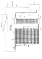
図1は、本発明に係る冷凍装置の一実施の形態を示す冷媒回路図である。この冷凍装置30は、圧縮機2、熱交換器(凝縮器)3、減圧装置5、及び蒸発器7を閉ループの冷媒配管で接続して構成されている。
【0013】
凝縮器3は、例えば、フィン・アンド・チューブ式の熱交換器であり、減圧装置5は、いわゆる電子制御弁である。
【0014】
蒸発器7の熱交換部は、メイン熱交換部7Aと、このメイン熱交換部7Aの下流に配置されるサブ熱交換部7Bとに分割されている。メイン熱交換部7Aは、フィン・アンド・チューブ式であり、冷媒管9A,9Bは、2系統に分かれ、いわゆる2パスの構成である。冷媒管9A,9Bは、メイン熱交換部7Aの出口7Cで合流し、合流後の冷媒は、メイン熱交換部7Aの下流に配置されるサブ熱交換部7Bに流入する。
【0015】
このサブ熱交換部7Bは、上部ヘッダ11と、この上部ヘッダ11に対し、ほぼ平行に配置された下部ヘッダ13とを備え、各ヘッダ11,13間には、鉛直方向に延びる複数本の冷媒管9Dが、冷媒を下から上に向けて流すことができるように、接続されている。
【0016】
下部ヘッダ13と圧縮機2の吸込管との間には、オイル戻し用のキャピラリーチューブ33が接続されている。
【0017】
また、上記構成においては、サブ熱交換部7Bにおける各冷媒管9Dの断面積の総和が、メイン熱交換部7Aにおける各冷媒管9A,9Bの断面積の総和よりも大きく設定されている。
【0018】
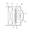
図2は、メイン熱交換部7A、並びにサブ熱交換部7Bの配置関係を示す図である。この蒸発器7は、冷凍装置30のケーシング14内に配置され、このケーシング14内には送風機15が付設され、この送風機15の風路内17には、風路の上流側からメイン熱交換部7A、及びサブ熱交換部7Bがその順に配置されている。16はファンガードである。
【0019】
サブ熱交換部7Bは、各ヘッダ11,13間に、それとほぼ平行に延びる複数枚のアルミニウム製のフィン21を備え、冷媒管9Dが、このフィン21の板面を貫通して構成されている。
【0020】
各フィン21は、風路の上流側が上を向き、冷媒管9Dの貫通部がほぼ水平となり、風路の下流側が下を向くように、傾斜して構成されている。この構成では、サブ熱交換部7Bでの結露水は、各フィン21の傾斜に沿って下に流れやすくなり、ファンガード16を通じて浸入する雨水は、各フィン21の傾斜によって遮断され、さらなる内側への浸入が阻止される。
【0021】
本実施形態では、冷凍装置30の冷凍サイクル内に二酸化炭素冷媒が封入されている。この二酸化炭素冷媒が封入された場合、図3のエンタルピ・圧力線図に示すように、ガス管31内は運転中に超臨界圧力で運転される。ガス管31内が、超臨界圧力で運転される冷媒には、二酸化炭素冷媒のほかに、例えばエチレン、ディボラン、エタン、酸化窒素等が挙げられる。図3では、圧縮機出口は状態aで示される。冷媒は、熱交換器を通って循環し、そこで状態bまで冷却され、熱を冷却空気に放出する。冷媒は、所望により、状態cまで冷却される。ついで、冷媒は、減圧装置での圧力低下により、状態dに至り、ここではガス/液体の2相混合体が形成される。冷媒は、蒸発器において、液相の蒸発により熱を吸収する。状態eは、蒸発器出口の状態であり、ガス相の冷媒は、熱交換器で状態fまで加熱されてから圧縮機2の吸込管に向かう。
【0022】
上記超臨界サイクルにおいて、圧縮機2から吐出される高圧単相ガス冷媒は、凝縮されないが、熱交換器において温度低下が起こる。熱交換器(状態b)における冷媒の最終温度は、冷却空気の温度よりも数度高い。そして、高圧ガスは熱交換器において、数度低い状態cまで冷却される。
【0023】
つぎに、冷凍装置30の動作を説明する。
【0024】
圧縮機2の吐出冷媒は、ガス管31を通じて凝縮器3に導かれ、この凝縮器3で熱交換し、冷却熱媒(例えば空気)に放熱した後、減圧装置5を経て蒸発器7に流入し、メイン熱交換部7A、及びサブ熱交換部7Bで順に蒸発して、ガス化した後、圧縮機2の吸込管に戻される。なお、超臨界ガスが使用された場合、当該超臨界ガスは、凝縮器3で凝縮しない。しかし、本明細書では、説明の便宜上、当該熱交換器3を凝縮器と呼称することにする。
【0025】
ところで、本実施形態では、メイン熱交換部7Aで蒸発しきれずに液バックした冷媒は、サブ熱交換部7Bの下部ヘッダ13に流入し、そこから複数本の冷媒管9Dにほぼ均等に分かれて流入し、この冷媒管9D内を下から上に流れる。そして、この間で、重力により液とガスとに分離され、下部ヘッダ13並びに冷媒管9Dの下部が液冷媒で満たされる。一方、サブ熱交換部7Bの上部では、乾き状態となり、或いは過熱ガス状態となり、この上部を通過した冷媒は、ほぼ完全に気化して圧縮機2に戻され、液冷媒は有効に利用される。
【0026】
本実施形態では、蒸発器7を通過した冷媒が、ほぼ完全に気化して圧縮機2に戻されるため、従来必要であったアキュムレータが不要になる。
【0027】
また、サブ熱交換部7Bを通過した冷媒は、ほぼ完全に気化して圧縮機2に戻されるため、従来のように、吸込管下部のオイル戻し孔等から液状態のまま冷媒が圧縮機に吸い込まれることがなくなり、オイル挙動等が安定化し、信頼性を向上させることができる。
【0028】
サブ熱交換部7Bの上部は、乾き状態となり、或いは過熱ガス状態となるため、当該部位への着霜が少なくなる。また、除霜運転時に、メイン熱交換部7Aで液バックが発生しても、サブ熱交換部7Bの上部で気化するため、圧縮機2への液バックを、ほぼ完全に抑えることができる。
【0029】
液バックの状態は、蒸発器7に対し、過剰に冷媒を供給しすぎた結果である。従って、減圧装置5を絞れば、液バックを抑制できる。減圧装置5の性能は、弁出入口の圧力差と、口径との関数となる。また、圧縮機2の圧縮効率は圧縮比の関数であり、高圧圧力が高いほど圧縮効率がよくなる。しかし、高圧圧力が低すぎると、減圧装置5の通過冷媒量が減少して、ガス欠状態となる。減圧装置5の弁口径を大きくすることにより、高圧圧力を低くすることが可能であるが、自動式の減圧装置5の場合、通過冷媒量が不安定となり、ハンチング現象を引き起こす。本実施形態では、液バック時に、減圧装置5の弁開度を大きく広げた状態(理論的にはほぼ全開の状態。)で、冷媒供給可能な範囲まで、圧縮機2の高圧圧力を上げて圧縮効率を向上させることができる。
【0030】
以上、一実施形態に基づいて本発明を説明したが、本発明は、これに限定されるものではない。
【0031】
【発明の効果】
本発明では、液冷媒を有効に蒸発させることができると共に、アキュムレータを不要にし、しかも、圧縮機内でのオイル挙動等を安定化させ、且つ、信頼性を向上させることができる。
【図面の簡単な説明】
【図1】本発明に係る冷凍装置の一実施の形態を示す冷媒回路図である。
【図2】メイン熱交換部、並びにサブ熱交換部の配置関係を示す図である。
【図3】超臨界サイクルのエンタルピ・圧力線図である。
【符号の説明】
2 圧縮機
3 熱交換器(凝縮器)
5 減圧装置
7 蒸発器
7A メイン熱交換部
7B サブ熱交換部
9A,9B,9D 冷媒管
11 上部ヘッダ
13 下部ヘッダ
15 送風機
17 風路
30 冷凍装置[0001]
TECHNICAL FIELD OF THE INVENTION
The present invention relates to a refrigeration apparatus that suppresses liquid back to a compressor.
[0002]
[Prior art]
2. Description of the Related Art In general, a refrigerating apparatus in which a compressor, a condenser, a decompression device, and an evaporator are connected by a closed-loop refrigerant pipe is known.
[0003]
In this type, an accumulator is generally connected to a suction pipe of the compressor to suppress liquid back to the compressor (see Patent Document 1). In this specification, the refrigeration apparatus includes a heat pump.
[0004]
[Patent Document 1]
JP 2001-165519 A, FIG.
[0005]
[Problems to be solved by the invention]
However, in the conventional configuration, even if the liquid refrigerant in the liquid bag is temporarily held in the accumulator, a part of the liquid refrigerant is sucked into the compressor in a liquid state from an oil return hole or the like below the suction pipe. Therefore, there is a problem that the liquid refrigerant is sucked into the compressor without being effectively used as evaporation heat, and the oil behavior and the like become unstable, thereby deteriorating reliability.
[0006]
Therefore, an object of the present invention is to solve the above-described problems of the conventional technology, to effectively evaporate the liquid refrigerant, to eliminate the need for an accumulator, and to stabilize the oil behavior and the like in the compressor. Another object of the present invention is to provide a refrigeration apparatus capable of improving reliability.
[0007]
[Means for Solving the Problems]
According to a first aspect of the present invention, in a refrigeration system including a compressor and an evaporator connected to a suction pipe of the compressor, a heat exchange unit of the evaporator includes a main heat exchange unit and a main heat exchange unit. It is divided into a sub heat exchange section disposed downstream of the exchange section, and the refrigerant pipe of the sub heat exchange section is formed to extend in the vertical direction.
[0008]
According to a second aspect of the present invention, in the first aspect, the sub heat exchange section includes an upper header and a lower header, and a plurality of refrigerant pipes extending in a vertical direction are connected between the headers. It is characterized by having.
[0009]
According to a third aspect of the present invention, in the first or second aspect, the total sum of the cross-sectional areas of the respective refrigerant tubes in the sub heat exchange unit is larger than the total sum of the cross-sectional areas of the respective refrigerant tubes in the main heat exchange unit. According to a fourth aspect of the present invention, the evaporator according to any one of the first to third aspects further comprises a blower provided in the evaporator, and the heat exchanger is provided in an air passage of the blower. The parts are arranged.
[0010]
According to a fifth aspect of the present invention, in any one of the first to fourth aspects, a refrigerant whose high pressure side is operated at a supercritical pressure is sealed in a refrigeration cycle of the refrigeration apparatus. And
[0011]
BEST MODE FOR CARRYING OUT THE INVENTION
Hereinafter, embodiments of the present invention will be described with reference to the drawings.
[0012]
FIG. 1 is a refrigerant circuit diagram showing one embodiment of a refrigeration apparatus according to the present invention. The refrigerating
[0013]
The
[0014]
The heat exchange part of the
[0015]
The sub
[0016]
A capillary tube 33 for returning oil is connected between the
[0017]
In the above configuration, the sum of the cross-sectional areas of the
[0018]
FIG. 2 is a diagram showing an arrangement relationship between the main
[0019]
The sub
[0020]
Each
[0021]
In the present embodiment, a carbon dioxide refrigerant is sealed in the refrigeration cycle of the
[0022]
In the supercritical cycle, the high-pressure single-phase gas refrigerant discharged from the
[0023]
Next, the operation of the
[0024]
The refrigerant discharged from the
[0025]
By the way, in the present embodiment, the refrigerant that has been liquid-backed without being completely evaporated in the main
[0026]
In the present embodiment, the refrigerant that has passed through the
[0027]
Further, since the refrigerant that has passed through the sub
[0028]
Since the upper part of the sub
[0029]
The state of the liquid bag is a result of excessively supplying the refrigerant to the
[0030]
As described above, the present invention has been described based on one embodiment, but the present invention is not limited to this.
[0031]
【The invention's effect】
ADVANTAGE OF THE INVENTION According to this invention, while being able to evaporate a liquid refrigerant effectively, an accumulator is unnecessary and the oil behavior etc. in a compressor can be stabilized and reliability can be improved.
[Brief description of the drawings]
FIG. 1 is a refrigerant circuit diagram showing an embodiment of a refrigeration apparatus according to the present invention.
FIG. 2 is a diagram showing an arrangement relationship between a main heat exchange unit and a sub heat exchange unit.
FIG. 3 is an enthalpy-pressure diagram of a supercritical cycle.
[Explanation of symbols]
2
5
Claims (5)
前記蒸発器の熱交換部が、メイン熱交換部と、このメイン熱交換部の下流に配置されるサブ熱交換部とに分割され、
このサブ熱交換部の冷媒管が鉛直方向に延びるように形成されていることを特徴とする冷凍装置。In a refrigeration apparatus including a compressor and an evaporator connected to a suction pipe of the compressor,
The heat exchanger of the evaporator is divided into a main heat exchanger and a sub heat exchanger disposed downstream of the main heat exchanger.
A refrigeration apparatus characterized in that a refrigerant pipe of the sub heat exchange section is formed to extend in a vertical direction.
Priority Applications (1)
| Application Number | Priority Date | Filing Date | Title |
|---|---|---|---|
| JP2003023501A JP2004232986A (en) | 2003-01-31 | 2003-01-31 | Refrigerator |
Applications Claiming Priority (1)
| Application Number | Priority Date | Filing Date | Title |
|---|---|---|---|
| JP2003023501A JP2004232986A (en) | 2003-01-31 | 2003-01-31 | Refrigerator |
Publications (1)
| Publication Number | Publication Date |
|---|---|
| JP2004232986A true JP2004232986A (en) | 2004-08-19 |
Family
ID=32952276
Family Applications (1)
| Application Number | Title | Priority Date | Filing Date |
|---|---|---|---|
| JP2003023501A Pending JP2004232986A (en) | 2003-01-31 | 2003-01-31 | Refrigerator |
Country Status (1)
| Country | Link |
|---|---|
| JP (1) | JP2004232986A (en) |
Cited By (5)
| Publication number | Priority date | Publication date | Assignee | Title |
|---|---|---|---|---|
| JP2007263432A (en) * | 2006-03-28 | 2007-10-11 | Sanyo Electric Co Ltd | Refrigerant cycle device |
| JP2007263433A (en) * | 2006-03-28 | 2007-10-11 | Sanyo Electric Co Ltd | Refrigerant cycle device and heat exchanger for the same |
| JP2013124802A (en) * | 2011-12-14 | 2013-06-24 | Panasonic Corp | Refrigeration cycle apparatus |
| CN104236173A (en) * | 2014-09-19 | 2014-12-24 | 西安交通大学 | Air-cooling evaporator with air-liquid separator |
| CN104729133A (en) * | 2015-03-24 | 2015-06-24 | 西安交通大学 | Double gas-liquid separator efficiency increasing and refrigerating circulating system for two-temperature direct-cooling refrigerator |
-
2003
- 2003-01-31 JP JP2003023501A patent/JP2004232986A/en active Pending
Cited By (5)
| Publication number | Priority date | Publication date | Assignee | Title |
|---|---|---|---|---|
| JP2007263432A (en) * | 2006-03-28 | 2007-10-11 | Sanyo Electric Co Ltd | Refrigerant cycle device |
| JP2007263433A (en) * | 2006-03-28 | 2007-10-11 | Sanyo Electric Co Ltd | Refrigerant cycle device and heat exchanger for the same |
| JP2013124802A (en) * | 2011-12-14 | 2013-06-24 | Panasonic Corp | Refrigeration cycle apparatus |
| CN104236173A (en) * | 2014-09-19 | 2014-12-24 | 西安交通大学 | Air-cooling evaporator with air-liquid separator |
| CN104729133A (en) * | 2015-03-24 | 2015-06-24 | 西安交通大学 | Double gas-liquid separator efficiency increasing and refrigerating circulating system for two-temperature direct-cooling refrigerator |
Similar Documents
| Publication | Publication Date | Title |
|---|---|---|
| JP5241872B2 (en) | Refrigeration cycle equipment | |
| JPH11304293A (en) | Refrigerant condenser | |
| WO2013080914A1 (en) | Air conditioner | |
| JP2008057807A (en) | Refrigerating cycle, and air conditioner and refrigerator using the same | |
| KR101173157B1 (en) | Air-Conditioning System for Vehicle having Water-Cooled Condenser and Water-Cooled Heat Exchanger for Supercooling | |
| JP2011214753A (en) | Refrigerating device | |
| US20130061628A1 (en) | Chiller | |
| US20130306272A1 (en) | Heat exchanger, and method for transferring heat | |
| JPWO2018225252A1 (en) | Heat exchanger and refrigeration cycle device | |
| JP6670197B2 (en) | Condenser for compression refrigerator | |
| JP6176470B2 (en) | refrigerator | |
| JP2004232986A (en) | Refrigerator | |
| JP6549469B2 (en) | Heat pump system | |
| KR100883600B1 (en) | Air conditioner | |
| CN208059355U (en) | Compression refrigerating machine condenser | |
| JP3650358B2 (en) | Air conditioner | |
| JP2004232924A (en) | Refrigeration cycle device | |
| JP2007057177A (en) | Vapor compression type refrigerating cycle device | |
| JP2018059655A (en) | Refrigeration cycle device | |
| JP2002340444A (en) | Evaporator and refrigerating machine having the same | |
| JP3298225B2 (en) | Air conditioner | |
| JP2019211138A (en) | Air conditioner | |
| JPH10253171A (en) | Air conditioner | |
| WO2023281655A1 (en) | Heat exchanger and refrigeration cycle device | |
| JP2012026686A (en) | Load-side device and refrigeration/cold-storage system |
Legal Events
| Date | Code | Title | Description |
|---|---|---|---|
| A711 | Notification of change in applicant |
Effective date: 20040819 Free format text: JAPANESE INTERMEDIATE CODE: A712 |
|
| A521 | Written amendment |
Free format text: JAPANESE INTERMEDIATE CODE: A821 Effective date: 20040819 |