JP2004232803A - Fluid enclosure-type vibration control device - Google Patents
Fluid enclosure-type vibration control device Download PDFInfo
- Publication number
- JP2004232803A JP2004232803A JP2003024383A JP2003024383A JP2004232803A JP 2004232803 A JP2004232803 A JP 2004232803A JP 2003024383 A JP2003024383 A JP 2003024383A JP 2003024383 A JP2003024383 A JP 2003024383A JP 2004232803 A JP2004232803 A JP 2004232803A
- Authority
- JP
- Japan
- Prior art keywords
- rubber elastic
- fluid
- elastic body
- diaphragm
- mounting member
- Prior art date
- Legal status (The legal status is an assumption and is not a legal conclusion. Google has not performed a legal analysis and makes no representation as to the accuracy of the status listed.)
- Granted
Links
Images


Classifications
-
- F—MECHANICAL ENGINEERING; LIGHTING; HEATING; WEAPONS; BLASTING
- F16—ENGINEERING ELEMENTS AND UNITS; GENERAL MEASURES FOR PRODUCING AND MAINTAINING EFFECTIVE FUNCTIONING OF MACHINES OR INSTALLATIONS; THERMAL INSULATION IN GENERAL
- F16F—SPRINGS; SHOCK-ABSORBERS; MEANS FOR DAMPING VIBRATION
- F16F13/00—Units comprising springs of the non-fluid type as well as vibration-dampers, shock-absorbers, or fluid springs
- F16F13/04—Units comprising springs of the non-fluid type as well as vibration-dampers, shock-absorbers, or fluid springs comprising both a plastics spring and a damper, e.g. a friction damper
- F16F13/06—Units comprising springs of the non-fluid type as well as vibration-dampers, shock-absorbers, or fluid springs comprising both a plastics spring and a damper, e.g. a friction damper the damper being a fluid damper, e.g. the plastics spring not forming a part of the wall of the fluid chamber of the damper
- F16F13/08—Units comprising springs of the non-fluid type as well as vibration-dampers, shock-absorbers, or fluid springs comprising both a plastics spring and a damper, e.g. a friction damper the damper being a fluid damper, e.g. the plastics spring not forming a part of the wall of the fluid chamber of the damper the plastics spring forming at least a part of the wall of the fluid chamber of the damper
- F16F13/10—Units comprising springs of the non-fluid type as well as vibration-dampers, shock-absorbers, or fluid springs comprising both a plastics spring and a damper, e.g. a friction damper the damper being a fluid damper, e.g. the plastics spring not forming a part of the wall of the fluid chamber of the damper the plastics spring forming at least a part of the wall of the fluid chamber of the damper the wall being at least in part formed by a flexible membrane or the like
- F16F13/103—Units comprising springs of the non-fluid type as well as vibration-dampers, shock-absorbers, or fluid springs comprising both a plastics spring and a damper, e.g. a friction damper the damper being a fluid damper, e.g. the plastics spring not forming a part of the wall of the fluid chamber of the damper the plastics spring forming at least a part of the wall of the fluid chamber of the damper the wall being at least in part formed by a flexible membrane or the like characterised by method of assembly, production or treatment
-
- F—MECHANICAL ENGINEERING; LIGHTING; HEATING; WEAPONS; BLASTING
- F16—ENGINEERING ELEMENTS AND UNITS; GENERAL MEASURES FOR PRODUCING AND MAINTAINING EFFECTIVE FUNCTIONING OF MACHINES OR INSTALLATIONS; THERMAL INSULATION IN GENERAL
- F16F—SPRINGS; SHOCK-ABSORBERS; MEANS FOR DAMPING VIBRATION
- F16F13/00—Units comprising springs of the non-fluid type as well as vibration-dampers, shock-absorbers, or fluid springs
- F16F13/04—Units comprising springs of the non-fluid type as well as vibration-dampers, shock-absorbers, or fluid springs comprising both a plastics spring and a damper, e.g. a friction damper
- F16F13/06—Units comprising springs of the non-fluid type as well as vibration-dampers, shock-absorbers, or fluid springs comprising both a plastics spring and a damper, e.g. a friction damper the damper being a fluid damper, e.g. the plastics spring not forming a part of the wall of the fluid chamber of the damper
- F16F13/08—Units comprising springs of the non-fluid type as well as vibration-dampers, shock-absorbers, or fluid springs comprising both a plastics spring and a damper, e.g. a friction damper the damper being a fluid damper, e.g. the plastics spring not forming a part of the wall of the fluid chamber of the damper the plastics spring forming at least a part of the wall of the fluid chamber of the damper
- F16F13/18—Units comprising springs of the non-fluid type as well as vibration-dampers, shock-absorbers, or fluid springs comprising both a plastics spring and a damper, e.g. a friction damper the damper being a fluid damper, e.g. the plastics spring not forming a part of the wall of the fluid chamber of the damper the plastics spring forming at least a part of the wall of the fluid chamber of the damper characterised by the location or the shape of the equilibration chamber, e.g. the equilibration chamber, surrounding the plastics spring or being annular
Landscapes
- Engineering & Computer Science (AREA)
- General Engineering & Computer Science (AREA)
- Mechanical Engineering (AREA)
- Manufacturing & Machinery (AREA)
- Combined Devices Of Dampers And Springs (AREA)
- Arrangement Or Mounting Of Propulsion Units For Vehicles (AREA)
Abstract
Description
【0001】
【技術分野】
本発明は、内部に封入された非圧縮性流体の流動作用に基づいて防振効果が発揮される流体封入式防振装置に係り、例えば自動車用のエンジンマウント等として有利に採用され得る、新規な構造の流体封入式防振装置に関するものである。
【0002】
【背景技術】
従来から、振動伝達系を構成する部材間に介装される防振連結体や防振支持体等としての防振装置の一種として、防振連結される一方の部材に取り付けられる第一の取付部材と防振連結される他方の部材に取り付けられる第二の取付部材を本体ゴム弾性体で連結する一方、壁部の一部が本体ゴム弾性体で構成されて振動入力時に圧力変動が及ぼされる受圧室と、壁部の一部が可撓性膜で構成されて容積変化が許容される平衡室を形成して、それら受圧室と平衡室に非圧縮性流体を封入すると共に、受圧室と平衡室をオリフィス通路によって相互に連通せしめた構造の流体封入式防振装置が、知られている(例えば、特許文献1参照)。このような構造の流体封入式防振装置は、オリフィス通路を流動せしめられる流体の共振作用に基づいて、ゴム弾性体だけでは得られ難い程に優れた防振効果を得ることが出来ることから、例えば自動車用エンジンマウントやボデーマウント等への適用が検討されている。
【0003】
ところで、従来構造の流体封入式防振装置では、可撓性膜が一般に薄肉のゴム弾性膜によって形成されており、そこにおいて、振動入力時にオリフィス通路を流動せしめられる流体の流動量を充分に確保して有効な防振効果を得るために、可撓性膜の膨出許容変形量を充分に大きくして平衡室の容積可変量を確保することが重要となる。
【0004】
ところが、可撓性膜の膨出許容変形量を大きくすると、例えばブラケット金具等の他部材が接近して配設されている場合に、大きく膨出変形した可撓性膜が他部材に干渉してしまい、可撓性膜の耐久性が低下する等という問題の発生するおそれがあった。
【0005】
なお、可撓性膜の耐久性を向上せしめるために可撓性膜の厚さ寸法を全体に亘って大きくすることも考えられるが、可撓性膜を肉厚とすると膨出許容変形量を充分に確保し難くなり、オリフィス通路を流動せしめられる流体流動量が減少してオリフィス効果が低下するおそれがある。
【0006】
また、可撓性膜の耐久性を向上させるために、例えば可撓性膜において他部材に干渉する部位だけをポイント的に肉厚とすることも考えられるが、結局、肉厚としても他部材に当接することに変わりなく、肉厚としない場合に比して、反対に当接時の打音が大きくなり易いという問題も、新たに発生することから、必ずしも妥当な方策ではないのである。
【0007】
【特許文献1】
特開2001−59540号公報
【0008】
【解決課題】
ここにおいて、本発明は上述の如き事情を背景として為されたものであって、その解決課題とするところは、可撓性膜の膨出変形に基づく平衡室の容積可変量を充分に確保しつつ、可撓性膜の他部材への当接に起因する耐久性の低下や打音の発生といった問題が可及的に低減乃至は回避され得る、新規な構造の流体封入式防振装置を提供することにある。
【0009】
【解決手段】
以下、このような課題を解決するために為された本発明の態様を記載する。なお、以下に記載の各態様において採用される構成要素は、可能な限り任意の組み合わせで採用可能である。また、本発明の態様乃至は技術的特徴は、以下に記載のものに限定されることなく、明細書全体および図面に記載され、或いはそれらの記載から当業者が把握することの出来る発明思想に基づいて認識されるものであることが理解されるべきである。
【0010】
(本発明の態様1)
本発明の態様1の特徴とするところは、防振連結される一方の部材に取り付けられる第一の取付部材と防振連結される他方の部材に取り付けられる第二の取付部材を本体ゴム弾性体で連結する一方、壁部の一部が該本体ゴム弾性体で構成されて振動入力時に圧力変動が及ぼされる受圧室と、壁部の一部が可撓性膜で構成されて容積変化が許容される平衡室を形成して、それら受圧室と平衡室に非圧縮性流体を封入すると共に、該受圧室と該平衡室をオリフィス通路によって相互に連通せしめた流体封入式防振装置において、前記可撓性膜をゴム弾性膜にて構成すると共に、該ゴム弾性膜を環状に厚肉として環状肉厚部を形成し、更に該環状肉厚部で囲まれた部分の略中央において該環状肉厚部から独立して厚肉の中央肉厚部を形成したことを、特徴とする。
【0011】
このような本態様に従う構造とされた流体封入式防振装置においては、ゴム弾性膜に膨出変形が惹起されると、ゴム弾性膜がその面に沿った方向に広がるように引張変形せしめられることとなるが、環状肉厚部は他の部分よりも厚肉とされていることにより引張方向のばね定数が大きくされていることにより、環状肉厚部の周方向で引張変形に対する拘束力が発生する。その結果、平衡室からゴム弾性膜の全体に均等な圧力が及ぼされた場合でも、環状肉厚部の形成部位の変形量が全体的に抑えられることとなる。
【0012】
ここにおいて、ゴム弾性膜は、その全体の弾性変形量が抑制される訳でなく、環状肉厚部の形成部位においてだけ弾性変形が抑えられることとなり、しかも、環状肉厚部の内側領域はゴム弾性膜が薄肉とされていることにより、かかる内側領域でも膨出方向の弾性変形が容易に許容されるようになっている。これにより、環状肉厚部は、ゴム弾性膜における必要以上の領域を拘束することなく、ゴム弾性膜の弾性変形に基づく平衡室の容積可変量を有利に確保しつつ、環状肉厚部の形成部位における膨出変形量を効果的に抑えることが出来るのである。
【0013】
しかも、環状肉厚部で囲まれた内側領域の部分には、平衡室の圧力によって最も大きく突出せしめられる中央部分に中央肉厚部が形成されていることから、この中央部分が他部材に当接するような場合でも、ゴム弾性膜の耐久性が有利に確保され得る。加えて、かかる内側領域は、その周囲が環状肉厚部で略拘束されていることにより、外方への膨出変形が抑えられることから、たとえ中央肉厚部が他部材に当接する場合でも、中央肉厚部の他部材への当接力が抑えられて、打音等の発生が軽減乃至は回避され得るのである。
【0014】
なお、本態様において、環状肉厚部と中央肉厚部のそれぞれの形状や肉厚寸法は、ゴム弾性膜の材質や要求特性,他部材との干渉クリアランス等を考慮して適宜に決定されるものであり、何等限定されるものでない。例えば、環状肉厚部と中央肉厚部を同じ肉厚寸法としても良いし、互いに異なる肉厚寸法としても良い。そこにおいて、環状肉厚部は、その内周部分および外周部分よりも厚肉とされていれば良く、また中央肉厚部は、その外周部分よりも厚肉とされていれば良い。また、それら環状肉厚部と中央肉厚部は、隣接する薄肉の外周部分等に対して、ゴム弾性膜の内面側と外面側の何れかに或いは両方に肉盛されて厚肉とされていても良い。更にまた、環状肉厚部と中央肉厚部は、一つの平衡室の壁部を構成するゴム弾性膜において、一つ或いは複数形成することが出来る。
【0015】
(本発明の態様2)
本発明の態様2は、本発明の前記態様1に係る流体封入式防振装置において、前記第一の取付部材と前記第二の取付部材の少なくとも一方に取付用ブラケットを設けると共に、前記ゴム弾性膜において該取付用ブラケットに対向位置する部分に、前記環状肉厚部および前記中央肉厚部を形成したことを、特徴とする。
【0016】
このような本態様においては、例えば第一の取付部材を防振連結される一方の部材に取り付けるための取付用ブラケットに対してゴム弾性膜が干渉する場合等において、平衡室の容積可変量ひいてはオリフィス通路を流動せしめられる流体量を有利に確保しつつ、ゴム弾性膜における耐久性の向上が図られ得る。従って、ゴム弾性膜の干渉のおそれがあるような取付ブラケットを採用することが可能となって、取付用ブラケットを含む流体封入式防振装置の配設スペースを小さく抑えることができると共に、取付ブラケットを含む流体封入式防振装置の設計自由度が向上され得る。
【0017】
(本発明の態様3)
本発明の態様3は、本発明の前記態様1又は態様2に係る流体封入式防振装置において、前記環状肉厚部の内外周縁部が、周上で明確な角部を持たない滑らかな湾曲形状とされていることを、特徴とする。本態様においては、環状肉厚部の内外周縁部に接する薄肉部分における応力集中が緩和されて亀裂等の発生が軽減されることにより、ゴム弾性膜の耐久性の更なる向上が図られ得る。
【0018】
(本発明の態様4)
本発明の態様4は、本発明の前記態様1乃至3の何れかの態様に係る流体封入式防振装置において、前記環状肉厚部が部分的に前記第一の取付部材または前記第二の取付部材に対して固着されていることを、特徴とする。本態様においては、ゴム弾性膜の弾性変形が強固に拘束されることとなる第一の取付部材や第二の取付部材との固着部位において、そこが環状肉厚部で厚肉とされていることから、かかる部位における耐久性ひいてはゴム弾性膜の耐久性の更なる向上が図られ得るのである。
【0019】
(本発明の態様5)
本発明の態様5は、本発明の前記態様1乃至4の何れかの態様に係る流体封入式防振装置において、前記ゴム弾性膜が湾曲した弛み部分を有していると共に、少なくとも前記環状肉厚部よりも内周側の領域を該弛み部分よりも平坦な領域に形成したことを、特徴とする。本態様においては、環状肉厚部や中央肉厚部によって肉厚が変化せしめられた部分の全体が出来るだけ平坦な領域に形成されることから、弾性変形に際して局部的な屈曲等に起因する応力集中が肉厚変化部分の存在によって増大されることが回避され得て、ゴム弾性膜における耐久性が一層有利に確保され得る。
【0020】
(本発明の態様6)
本発明の態様6は、本発明の前記態様1乃至5の何れかの態様に係る流体封入式防振装置において、前記第一の取付部材を前記本体ゴム弾性体の中央部分に固着すると共に、前記第二の取付部材を該本体ゴム弾性体の外周部分に固着して、それら第一の取付部材と第二の取付部材を該本体ゴム弾性体で連結する一方、該本体ゴム弾性体の一方の側に前記受圧室を形成すると共に、該本体ゴム弾性体の他方の面を覆うように前記ゴム弾性膜を配設して、該ゴム弾性膜の中央部分を該第一の取付部材に固着すると共に、該ゴム弾性膜の外周部分を該第二の取付部材に固着することにより、該本体ゴム弾性体の他方の側に前記平衡室を形成したことを、特徴とする。
【0021】
このように本態様においては、第一の取付部材と第二の取付部材を弾性連結する本体ゴム弾性体を挟んだ両側に受圧室と平衡室が形成されることから、防振装置全体のサイズ、特に主たる振動入力方向となる防振装置の中心軸方向のサイズをコンパクトにすることが出来ると共に、本体ゴム弾性体の外側に配設されて外部に露呈されることから他部材に干渉し易いゴム弾性膜の耐久性も有利に確保することが可能となるのである。
【0022】
【発明の実施形態】
以下、本発明を更に具体的に明らかにするために、本発明の実施形態について、図面を参照しつつ、詳細に説明する。
【0023】
先ず、図1〜4には、本発明の第一の実施形態としての自動車用エンジンマウント10が示されている。このエンジンマウント10は、第一の取付部材としての第一の取付金具12と第二の取付部材としての第二の取付金具14が本体ゴム弾性体16によって弾性的に連結された構造とされており、第一の取付金具12が図示しない自動車のパワーユニットに取り付けられる一方、第二の取付金具14が図示しない自動車のボデーに取り付けられることにより、パワーユニットをボデーに対して防振支持するようになっている。また、そのような装着状態下、第一の取付金具12と第二の取付金具14の間には、パワーユニットの分担荷重と、防振すべき主たる振動が、何れも、エンジンマウント10の略軸方向(図1中、上下方向)に入力されるようになっている。なお、以下の説明中、上下方向とは、原則として、図1中の上下方向を言うものとする。
【0024】
より詳細には、第一の取付金具12は、本体ゴムインナ金具18とダイヤフラムインナ金具20によって構成されていると共に、第二の取付金具14は、本体ゴムアウタ筒金具22とダイヤフラムアウタ筒金具24および蓋板金具26によって構成されている。そして、本体ゴム弾性体16に対して本体ゴムインナ金具18と本体ゴムアウタ筒金具22が加硫接着されて第一の一体加硫成形品28とされている一方、ダイヤフラムインナ金具20とダイヤフラムアウタ筒金具24が、ゴム弾性膜としてのダイヤフラム30に対して加硫接着されて第二の一体加硫成形品32とされており、これら第一及び第二の一体加硫成形品28,32が相互に組み合わされている。
【0025】
ここにおいて、先ず第一の一体加硫成形品28を構成する本体ゴムインナ金具18は、逆向きの略円錐台形状を有している。また、本体ゴムインナ金具18の上端面(大径側端面)には、嵌合凹部34が形成されていると共に、該嵌合凹部34の底面に開口するねじ穴38が形成されている。
【0026】
更にまた、本体ゴムアウタ筒金具22は、略大径円筒形状を有する筒壁部40を備えており、この筒壁部40の軸方向下端部には径方向外方に向かって広がるフランジ状部42が一体形成されている。更にまた、筒壁部40の軸方向上端部分は、軸方向上方に行くに従って次第に拡開するテーパ筒状部44とされている。これによって、本体ゴムアウタ筒金具22の外周側には、外周面に開口して周方向に一周弱の長さで延びる周溝45が形成されている。そして、本体ゴムアウタ筒金具22の上方に離隔して、本体ゴムインナ金具18が略同一中心軸上で離隔配置されており、本体ゴムインナ金具18における逆テーパ形状の外周面と本体ゴムアウタ筒金具22におけるテーパ筒状部44の内周面が相互に離隔して対向位置せしめられており、これら本体ゴムインナ金具18の外周面と本体ゴムアウタ筒金具22におけるテーパ筒状部44の内周面との対向面間が、本体ゴム弾性体16によって弾性的に連結されている。
【0027】
かかる本体ゴム弾性体16は、全体として大径の円錐台形状を有しており、その中央部分には、本体ゴムインナ金具18が同軸的に配されて加硫接着されていると共に、その大径側端部外周面に対して本体ゴムアウタ筒金具22のテーパ筒状部44が重ね合わせられて加硫接着されている。これによって、本体ゴム弾性体16が、上述の如き本体ゴムインナ金具18および本体ゴムアウタ筒金具22を備えた第一の一体加硫成形品28として形成されている。
【0028】
また一方、第二の一体加硫成形品32を構成するダイヤフラムインナ金具20は、厚肉の円板形状を有している。また、ダイヤフラムインナ金具20の下面には、嵌合凸部46が形成されていると共に、該嵌合凸部46の形成部位を貫通して挿通孔52が形成されている。更にダイヤフラムインナ金具20には、上方に突出して取付板部58が一体形成されている。この取付板部58は竪形の矩形平板形状を有しており、中央部分にはボルト挿通孔59が設けられている。
【0029】
また、ダイヤフラムアウタ筒金具24は、薄肉大径の円筒形状を有しており、その軸方向上側の開口部には、径方向外方に向かって広がる取付用板部62が一体形成されている。なお、取付用板部62には、複数の挿通孔が形成されており、それらの挿通孔に対してそれぞれ固定ボルト64が圧入されて植設されている。更にまた、ダイヤフラムアウタ筒金具24の軸方向下側の開口部には、径方向外方に向かって広がる円環板形状のフランジ状部66が一体形成されており、更に、フランジ状部66の外周縁部には、軸方向下方に向かって突出する円環状のかしめ片68が一体形成されている。
【0030】
そして、ダイヤフラムアウタ筒金具24の軸方向上方に離隔して、ダイヤフラムインナ金具20が、略同一中心軸上に配設されており、それらダイヤフラムインナ金具20とダイヤフラムアウタ筒金具24が、ダイヤフラム30によって連結されている。
【0031】
ダイヤフラム30は、薄肉のゴム膜によって形成されており、容易に弾性変形が許容されるように大きな弛みを持った湾曲断面形状をもって周方向に延びる略円環形状を有している。そして、ダイヤフラム30の内周縁部が、ダイヤフラムインナ金具20の外周縁部に対して加硫接着されていると共に、ダイヤフラム30の外周縁部が、ダイヤフラムアウタ筒金具24の軸方向上側の開口部に加硫接着されている。これにより、ダイヤフラム30は、ダイヤフラムインナ金具20およびダイヤフラムアウタ筒金具24を備えた第二の一体加硫成形品32として形成されている。
【0032】
ここにおいて、ダイヤフラム30は、周上の一部において断面形状が異ならされており、外方への突出量の小さい当接予定部67とされている。即ち、ダイヤフラム30は、基本的に外方に向かって凸となる円弧形をもってダイヤフラムインナ金具20とダイヤフラムアウタ筒金具24を繋ぐように径方向に延びる断面形状をもって環状に形成されているが、周上の一カ所に設けられた当接予定部67においては、外方への突出量が抑えられて略平坦で僅かに内方にえぐられたように湾曲せしめられた板形状とされている。
【0033】
また、この当接予定部67は、その外周部分が環状に厚肉とされており、以て、環状肉厚部69が形成されている。特に本実施形態では、環状肉厚部69の内周縁部および外周縁部が、何れも、角部を丸くした略矩形状とされており、周方向に明確な角部が形成されていないことにより、変形に際しての応力や変形の集中が軽減されるようになっている。
【0034】
更にまた、当接予定部67は、環状肉厚部69の内周側に位置する内側領域71の肉厚寸法が該環状肉厚部69よりも薄肉とされており、特に本実施形態では、環状肉厚部69の内周側と外周側の肉厚が略同じとされている。そして、この薄肉とされた内側領域71の略中央には、中央肉厚部73が形成されている。この中央肉厚部73は、内側領域71よりも肉厚寸法が大きくされており、特に本実施形態では、中央肉厚部73と環状肉厚部69の厚さ寸法が略同じとされている。なお、中央肉厚部73の周囲は全周に亘って薄肉の内側領域71で囲まれており、それによって中央肉厚部73が環状肉厚部69から離隔して独立位置せしめられている。なお、中央肉厚部73および環状肉厚部69は、ダイヤフラム30に対して表裏何れの面側に厚肉とされていても良い。
【0035】
また、本実施形態では、環状肉厚部69の外周縁部の一部がダイヤフラム30の湾曲部分まで広がっているが、少なくとも環状肉厚部69の内周縁部、即ち内側領域71の形成部分は、実質的に平板形状とされた当接予定部67の領域内に形成されている。なお、環状肉厚部69の外周縁部の一部は、ダイヤフラム30におけるダイヤフラムアウタ筒金具24との接着部分に至るまで広がっている。
【0036】
而して、かかる第二の一体加硫成形品32が、前述の第一の一体加硫成形品28に対して上方から重ね合わせられて組み付けられており、ダイヤフラムインナ金具20が本体ゴムインナ金具18に固着されていると共に、ダイヤフラムアウタ筒金具24が本体ゴムアウタ筒金具22に固着されており、更にダイヤフラム30が、本体ゴム弾性体16の外方に離隔して、本体ゴム弾性体16の外周面を全体に亘って覆うようにして配設されている。
【0037】
すなわち、ダイヤフラムインナ金具20が本体ゴムインナ金具18の上面に直接に重ね合わされて、ダイヤフラムインナ金具20の嵌合凸部46が本体ゴムインナ金具18の嵌合凹部34に嵌め込まれることによって、ダイヤフラムインナ金具20と本体ゴムインナ金具18が同一中心軸上に位置合わせされている。また、特に本実施形態では、嵌合凸部46と嵌合凹部34の各外周面に切欠状に形成された係合外周面50と係合内周面36の係合作用によって、ダイヤフラムインナ金具20と本体ゴムインナ金具18が周方向でも相互に位置決めされており、ダイヤフラムインナ金具20の挿通孔52と本体ゴムインナ金具18のねじ穴38が位置合わせされている。
【0038】
そして、図1,2に示されているように、本体ゴムインナ金具18とダイヤフラムインナ金具20を重ね合わせた状態下で、連結ボルト70を、ダイヤフラムインナ金具20の挿通孔52を通じて本体ゴムインナ金具18のねじ穴38に螺着されている。而して、これら本体ゴムインナ金具18とダイヤフラムインナ金具20が連結ボルト70で連結固定されることにより、第一の取付金具12が構成されている。
【0039】
一方、ダイヤフラムアウタ筒金具24は本体ゴムアウタ筒金具22に対して軸方向上方から外挿されている。そして、本体ゴムアウタ筒金具22は、その下端部において、フランジ状部66の外周縁部がダイヤフラムアウタ筒金具24のフランジ状部66に対して軸方向に重ね合わされていると共に、その上端部において、テーパ筒状部44の開口端縁部がダイヤフラムアウタ筒金具24の内周面に対して径方向で重ね合わされている。そして、本体ゴムアウタ筒金具22のフランジ状部66の外周縁部に対して、ダイヤフラムアウタ筒金具24のかしめ片68がかしめ固定されることによって、本体ゴムアウタ筒金具22とダイヤフラムアウタ筒金具24が相互に固定されて組み付けられている。なお、これら本体ゴムアウタ筒金具22の上下両端部におけるダイヤフラムアウタ筒金具24との重ね合わせ部位には、それぞれ、本体ゴム弾性体16またはダイヤフラム30と一体成形されたシールゴムが介在されており、流体密にシールされている。
【0040】
これにより、本体ゴムアウタ筒金具22に形成された周溝45がダイヤフラムアウタ筒金具24で流体密に覆蓋されており、以て、本体ゴムアウタ筒金具22の筒壁部40とダイヤフラムアウタ筒金具24の径方向対向面間を周方向に所定長さで乃至は全周に亘って連続して延びる環状通路72が形成されている。更に、本体ゴムアウタ筒金具22の下側には、大径の円板形状を有する蓋板金具26が重ね合わせられており、蓋板金具26の外周縁部が、本体ゴムアウタ筒金具22のフランジ状部42の外周縁部に重ね合わされて、該フランジ状部42と共に、ダイヤフラムアウタ筒金具24のかしめ片68でかしめ固定されている。これにより、本体ゴムアウタ筒金具22の下側開口が、蓋板金具26によって流体密に覆蓋されている。なお、本体ゴムアウタ筒金具22と蓋板金具26の重ね合わせ部位は、本体ゴム弾性体16と一体成形されたシールゴムが介在せしめられて流体密に封止されている。
【0041】
また、このようにして相互に組み付けられたダイヤフラムアウタ筒金具24と本体ゴムアウタ筒金具22および蓋板金具26が互いにかしめ固定されることによって第二の取付金具14が構成されており、かかる第二の取付金具14が、本体ゴム弾性体16を介して、第一の取付金具12に対して弾性連結されている。
【0042】
さらに、上述の如く第二の取付金具14の下端開口部が蓋板金具26で流体密に覆蓋されることにより、本体ゴム弾性体16と蓋板金具26の対向面間には、非圧縮性流体が封入された受圧室76が形成されている。この受圧室76は、壁部の一部が本体ゴム弾性体16で構成されており、第一の取付金具12と第二の取付金具14の間への振動入力時に本体ゴム弾性体16の弾性変形に基づいて振動が入力されて圧力変動が惹起されるようになっている。
【0043】
また、本体ゴム弾性体16とダイヤフラム30が、それぞれの内周縁部と外周縁部において第一の取付金具12と第二の取付金具14に固着されることにより、本体ゴム弾性体16とダイヤフラム30の対向面間には、非圧縮性流体が封入された平衡室78が形成されている。即ち、この平衡室78は、壁部の一部が変形容易なダイヤフラム30で構成されており、該ダイヤフラム30の弾性変形に基づいて容易に容積変化が許容されるようになっているのである。なお、受圧室76や平衡室78に封入される非圧縮性流体としては、後述するオリフィス通路80を通じて流動せしめられる流体の共振作用に基づく防振効果を自動車用のエンジンマウント10に要求される振動周波数域で効率的に得るために、一般に、0.1Pa.s以下の低粘性流体が好適に採用される。
【0044】
さらに、このように本体ゴム弾性体16を挟んで下側に形成された受圧室76と上側に形成された平衡室78には、第二の取付金具14内に形成された環状通路72が、その周方向両端部に形成された連通孔82,84を通じて接続されており、それによって、受圧室76と平衡室78を相互に連通せしめて両室76,78間での流体流動を許容するオリフィス通路80が所定長さで形成されている。そして、公知の如く、振動入力時に受圧室76と平衡室78の間に生ぜしめられる相対的な圧力変動に基づいてオリフィス通路80を通じての流体流動が生ぜしめられることとなり、以て、かかる流体の共振作用等の流動作用に基づいて入力振動に対して有効な防振効果が発揮されるようになっているのである。なお、オリフィス通路80を流動せしめられる流体の流動作用に基づいて発揮される防振効果は、オリフィス通路80の通路断面積と通路長さの比をチューニングすること等によって、周波数特性を調節することが可能である。
【0045】
このような構造とされたエンジンマウント10は、図面上に明示はされていないが、第一の取付金具12における取付板部58が自動車のパワーユニットに対して固定される一方、第二の取付金具14における取付用板部62が自動車のボデーに重ね合わされて連結ボルト70で固定されることとなり、それによって、パワーユニットとボデーの間に装着されて、パワーユニットをボデーに対して防振支持せしめるようにされる。
【0046】
特に本実施形態では、第一の取付金具12が、ブラケット74を介して、パワーユニットに固定されて取り付けられるようになっている。このブラケット74は、図5に示されているように、ダイヤフラムインナ金具20の取付板部58に対して取付ボルト75で固定されることによって第一の取付金具12に固着されており、第一の取付金具12からマウント中心軸に直交する方向に延び出している。そして、図示はされていないが、例えば、ブラケット74の適当な部位に設けられた挿通孔に挿通されるボルト等で、かかるブラケット74が自動車のパワーユニットに固定されるようになっている。
【0047】
そして、エンジンマウント10は、本体ゴム弾性体16の外側を覆うように配設されたダイヤフラム30が、その周上の一部において、ブラケット74の下面に対して対向位置せしめられることとなるが、かかるブラケット74に対向位置する部分に当接予定部67が位置せしめられるようになっている。
【0048】
而して、かかる装着状態下では、第一の取付金具12と第二の取付金具14の間に及ぼされる振動に対して、受圧室76と平衡室78の間に惹起される相対的な圧力変動に基づいてオリフィス通路80を流動せしめられる流体の共振作用等による防振効果が発揮されることとなる。
【0049】
そこにおいて、上述の如き構造とされたエンジンマウント10においては、受圧室76の内圧変化がオリフィス通路80を通じて平衡室78に及ぼされることとなり、平衡室78の圧力変動に伴ってダイヤフラム30が拡縮変形せしめられることとなる。そこにおいて、かかるダイヤフラム30は、ブラケット74に対向位置せしめられているが、その対向部分が外方への突出量が小さくされた当接予定部67で構成されていることから、平衡室78の圧力増大によってダイヤフラム30が外方に膨出変形せしめられた際にも、ダイヤフラム30のブラケット74に対する干渉が軽減される。
【0050】
しかも、かかる当接予定部67は、環状肉厚部69と内側領域71,中央肉厚部73を組み合わせた特定構造をもって形成されていることにより、その耐久性が極めて有利に確保され得るのである。即ち、環状肉厚部69が形成されていることにより、当接予定部67には、環状の補強材が一体形成されているに等しいのであり、ダイヤフラム30が膨出変形する際には、ダイヤフラム30の全ての部位に対して面に沿った全方向の引張力が作用するが、環状肉厚部69の形成部位では、該環状肉厚部69の周方向で高ばね化されて弾性変形が抑えられることにより、周方向で応力や変形を略均一に分散して応力集中を回避せしめつつ、当接予定部67の膨出変形量が有効に抑えられ、ブラケット74への干渉が防止され得るのである。
【0051】
また、環状肉厚部69の内側領域71は、薄肉とされていることから、適度な膨出変形量が許容され得るのであり、必要以上に膨出変形量が制限されることによって平衡室78の容積可変量が不足する等の問題が回避され得る。更に、もし当接予定部67の膨出変形量が過大となってブラケット74への干渉が発生した場合でも、最も外方への突出量が大きくなる内側領域71の中央部分には、厚肉の中央肉厚部73が形成されており、この中央肉厚部73がブラケット74に当接せしめられることから、当接部位における耐久性も有利に確保され得る。
【0052】
すなわち、薄肉の内側領域71を形成しないで当接予定部67の全体を厚肉とすると、平衡室78の容積可変量を充分に確保することが難しくなる場合がある。また、かかる問題を解決するためには、例えば全体を厚肉とした当接予定部67の大きさを小さくすれば良いことになるが、当接予定部67の大きさを小さくすると変形時に応力集中が発生し易く耐久性の低下が避けられないのである。これに対して、本実施形態の如く、環状肉厚部69を採用して、その内側領域71を薄肉とすることにより、平衡室78の容積可変量を適当に確保しつつ、当接予定部67の広い領域で応力を分散しながら膨出変形量を抑えることが出来るのであり、容積可変量の確保と膨出変形量の抑制が高度に両立して実現可能となるのである。
【0053】
以上、本発明の一実施形態について詳述してきたが、これはあくまでも例示であって、本発明は、かかる実施形態における具体的な記載によって、何等、限定的に解釈されるものでなく、当業者の知識に基づいて種々なる変更,修正,改良等を加えた態様において実施され得るものであり、また、そのような実施態様が、本発明の趣旨を逸脱しない限り、何れも、本発明の範囲内に含まれるものであることは、言うまでもない。
【0054】
例えば、前記実施形態では、当接予定部67がダイヤフラム30の周上の一カ所だけに形成されていたが、ブラケット等の当接可能性のある他部材がダイヤフラム30の周上の複数箇所にある場合には、それらに対応する部位に、それぞれ、環状肉厚部69や内側領域71および中央肉厚部73からなる当接予定部を形成しても良い。
【0055】
また、前記実施形態では、本体ゴム弾性体16の外側を覆うようにダイヤフラム30が配設されていたが、ダイヤフラムの配設領域や組付構造等は、何等限定されるものでなく、例えば、特開2000−274480号公報等に記載されているように、円筒形状を有する第二の取付金具において一方の開口部を本体ゴム弾性体で覆蓋せしめる一方、他方の開口部をダイヤフラムで配設し、それら本体ゴム弾性体とダイヤフラムの対向面間を、第二の取付金具で支持せしめた仕切部材で仕切ることにより、該仕切部材を挟んだ一方の側に、壁部の一部が本体ゴム弾性体で構成された受圧室を形成すると共に、仕切部材を挟んだ他方の側に、壁部の一部がダイヤフラムで構成された平衡室を形成せしめた構造の流体封入式マウントにおいて、かかるダイヤフラムの中央部分等の適当な箇所に、上述の如き特定構造の当接予定部を形成することも可能である。
【0056】
また、前記実施形態では、入力される振動によって封入流体に対して圧力変動や流動が受動的に生ぜしめられることを利用して防振効果を得るようにした、所謂受動的な防振装置に対して本発明を適用したものの一具体例を示したが、本発明は、前記特許文献1等に記載されているように、アクチュエータを設けて、封入された非圧縮性流体の圧力変動を能動的に制御することにより防振特性を変更設定したり、振動を相殺的に低減せしめるようにした能動的な防振装置に対しても、同様に適用可能である。
【0057】
加えて、前記実施形態では、何れも、本発明を自動車用エンジンマウントに適用した場合について説明したが、本発明は、自動車用のボデーマウントやメンバマウント等、或いは自動車以外の各種装置における防振装置に対しても、同様に適用可能である。
【0058】
【発明の効果】
上述の説明から明らかなように、本発明に従う構造とされた流体封入式防振装置においては、平衡室における容積可変量を確保しつつ、該平衡室の壁部を構成するゴム弾性膜における膨出変形量を、応力や変形の集中を回避しつつ効果的に抑えることが可能となるのであり、それによって、ゴム弾性膜の他部材への干渉に起因する耐久性の低下が有利に回避可能となる。
【図面の簡単な説明】
【図1】本発明の第一の実施形態としてのエンジンマウントの縦断面図であって、図3におけるI−I断面に相当する図である。
【図2】図1に示されたエンジンマウントの図1と異なる縦断面を示す図であって、図3におけるII−II断面に相当する図である。
【図3】図1に示されたエンジンマウントを構成する第一の一体加硫成形品を示す平面図である。
【図4】図1に示されたエンジンマウントを構成する第二の一体加硫成形品を示す平面図である。
【図5】図1に示されたエンジンマウントの正面図であって、図4におけるV −V 矢視図である。
【図6】図1に示されたエンジンマウントの装着状態下でのダイヤフラムの膨出変形状態を示す説明図である。
【符号の説明】
10 エンジンマウント
12 第一の取付金具
14 第二の取付金具
16 本体ゴム弾性体
67 当接予定部
69 環状肉厚部
71 内側領域
73 中央肉厚部
74 ブラケット
76 受圧室
78 平衡室
80 オリフィス通路[0001]
【Technical field】
The present invention relates to a fluid-filled vibration isolator that exhibits a vibration isolation effect based on the flow action of an incompressible fluid enclosed therein, and can be advantageously employed as an engine mount for automobiles, for example. The present invention relates to a fluid-filled vibration isolator having a simple structure.
[0002]
[Background]
Conventionally, as a type of anti-vibration device as an anti-vibration coupling body or anti-vibration support body interposed between members constituting the vibration transmission system, the first attachment attached to one member to be anti-vibration connected The second attachment member attached to the other member that is vibration-proof connected to the member is connected by the main rubber elastic body, while a part of the wall portion is constituted by the main rubber elastic body, and pressure fluctuation is exerted when vibration is input. A pressure receiving chamber and an equilibrium chamber in which a part of the wall portion is made of a flexible membrane and volume change is allowed, and an incompressible fluid is sealed in the pressure receiving chamber and the equilibrium chamber; A fluid-filled vibration isolator having a structure in which equilibrium chambers are communicated with each other by an orifice passage is known (for example, see Patent Document 1). Since the fluid-filled vibration isolator having such a structure can obtain an excellent vibration isolation effect that is difficult to obtain with a rubber elastic body alone, based on the resonance action of the fluid that flows through the orifice passage. For example, application to engine mounts and body mounts for automobiles is being studied.
[0003]
By the way, in a fluid-filled vibration isolator having a conventional structure, the flexible film is generally formed of a thin rubber elastic film, in which a sufficient amount of fluid is allowed to flow through the orifice passage when vibration is input. In order to obtain an effective anti-vibration effect, it is important to secure a variable volume of the equilibrium chamber by sufficiently increasing the bulging allowable deformation amount of the flexible membrane.
[0004]
However, when the bulging allowable deformation amount of the flexible film is increased, for example, when other members such as bracket fittings are arranged close to each other, the bulged and deformed flexible film interferes with the other members. As a result, there is a risk that the durability of the flexible film may be lowered.
[0005]
In order to improve the durability of the flexible membrane, it is conceivable to increase the thickness of the flexible membrane over the whole, but if the flexible membrane is thick, the bulging allowable deformation amount is reduced. It becomes difficult to ensure sufficient, and there is a possibility that the amount of fluid flowing through the orifice passage is reduced and the orifice effect is lowered.
[0006]
In order to improve the durability of the flexible membrane, for example, it is conceivable that only the portion of the flexible membrane that interferes with the other member is made thicker in a point. As compared with the case where the wall thickness is not increased, the problem that the hitting sound at the time of contact tends to increase is also newly generated, and is not necessarily an appropriate measure.
[0007]
[Patent Document 1]
JP 2001-59540 A
[0008]
[Solution]
Here, the present invention has been made in the background as described above, and the problem to be solved is to ensure a sufficient volume variable amount of the equilibrium chamber based on the bulging deformation of the flexible membrane. However, a fluid-filled vibration isolator having a novel structure capable of reducing or avoiding problems such as a decrease in durability and the occurrence of hitting sound due to the contact of the flexible membrane with other members. It is to provide.
[0009]
[Solution]
Hereinafter, the aspect of this invention made | formed in order to solve such a subject is described. In addition, the component employ | adopted in each aspect as described below is employable by arbitrary combinations as much as possible. In addition, aspects or technical features of the present invention are not limited to those described below, but are described in the entire specification and drawings, or can be understood by those skilled in the art from those descriptions. It should be understood that it is recognized on the basis of.
[0010]
(Aspect 1 of the present invention)
A feature of the first aspect of the present invention is that the first attachment member attached to one member to be anti-vibrated and the second attachment member attached to the other member to be anti-vibration and connected to the main rubber elastic body On the other hand, a part of the wall part is made of the main rubber elastic body, and a pressure receiving chamber in which pressure fluctuation is exerted when vibration is input, and a part of the wall part is made of a flexible film, and volume change is allowed. In the fluid-filled vibration isolator in which an incompressible fluid is enclosed in the pressure receiving chamber and the equilibrium chamber, and the pressure receiving chamber and the equilibrium chamber are connected to each other by an orifice passage. The flexible film is formed of a rubber elastic film, and the rubber elastic film is annularly thickened to form an annular thick part. Further, the annular thick film is formed at the approximate center of the portion surrounded by the annular thick part. Forming a thick central wall independently of the thick part And it features.
[0011]
In the fluid-filled vibration isolator having the structure according to this embodiment, when the bulging deformation is induced in the rubber elastic film, the rubber elastic film is tensilely deformed so as to spread in the direction along the surface. However, since the annular thick part is thicker than the other parts, the spring constant in the tensile direction is increased, so that the restraining force against tensile deformation in the circumferential direction of the annular thick part is increased. Occur. As a result, even when an equal pressure is applied from the equilibrium chamber to the entire rubber elastic membrane, the deformation amount of the formation portion of the annular thick portion is suppressed as a whole.
[0012]
Here, the elastic elastic film does not suppress the amount of elastic deformation of the whole, but elastic deformation is suppressed only at the formation part of the annular thick part, and the inner region of the annular thick part is rubber. Since the elastic film is thin, elastic deformation in the bulging direction is easily allowed even in such an inner region. As a result, the annular thick portion can be formed without restricting an unnecessarily large area in the rubber elastic membrane, while advantageously ensuring a variable volume of the equilibrium chamber based on the elastic deformation of the rubber elastic membrane. The amount of bulging deformation at the site can be effectively suppressed.
[0013]
In addition, since the central thick portion is formed in the central portion that is projected most greatly by the pressure in the equilibrium chamber, the central thick portion is formed in the inner region surrounded by the annular thick portion. Even in the case of contact, the durability of the rubber elastic membrane can be advantageously ensured. In addition, since the inner region is restrained by the annular thick part at the periphery, the outward bulging deformation is suppressed, so even if the central thick part abuts against other members. In addition, the contact force of the central thick portion with the other members can be suppressed, and the occurrence of a hitting sound or the like can be reduced or avoided.
[0014]
In this embodiment, the shape and thickness of each of the annular thick part and the central thick part are appropriately determined in consideration of the material and required characteristics of the rubber elastic film, interference clearance with other members, and the like. It is a thing and is not limited at all. For example, the annular thick portion and the central thick portion may have the same thickness dimension, or may have different thickness dimensions. Here, the annular thick portion only needs to be thicker than the inner peripheral portion and the outer peripheral portion, and the central thick portion only needs to be thicker than the outer peripheral portion. In addition, the annular thick part and the central thick part are thickened on one or both of the inner surface side and the outer surface side of the rubber elastic film with respect to the adjacent thin outer peripheral portion or the like. May be. Furthermore, one or a plurality of annular thick portions and central thick portions can be formed in the rubber elastic film constituting the wall portion of one equilibrium chamber.
[0015]
(Aspect 2 of the present invention)
According to a second aspect of the present invention, in the fluid-filled vibration isolator according to the first aspect of the present invention, a mounting bracket is provided on at least one of the first mounting member and the second mounting member, and the rubber elasticity The annular thick portion and the central thick portion are formed in a portion of the membrane facing the mounting bracket.
[0016]
In this embodiment, for example, when the rubber elastic film interferes with the mounting bracket for mounting the first mounting member on one of the vibration-proof connected members, the volume of the balance chamber can be changed. The durability of the rubber elastic membrane can be improved while advantageously ensuring the amount of fluid that can flow through the orifice passage. Accordingly, it is possible to employ a mounting bracket that may cause interference with the rubber elastic membrane, and the installation space of the fluid-filled vibration isolator including the mounting bracket can be kept small. The degree of freedom of design of the fluid filled type vibration damping device including can be improved.
[0017]
(Aspect 3 of the present invention)
Aspect 3 of the present invention is a fluid-filled vibration isolator according to aspect 1 or aspect 2 of the present invention, wherein the inner and outer peripheral edge portions of the annular thick portion do not have clear corners on the circumference. It is characterized by being shaped. In this aspect, the stress concentration in the thin wall portion in contact with the inner and outer peripheral edge portions of the annular thick portion is alleviated and the occurrence of cracks or the like is reduced, so that the durability of the rubber elastic film can be further improved.
[0018]
(Aspect 4 of the present invention)
Aspect 4 of the present invention is the fluid-filled vibration isolator according to any one of the aspects 1 to 3 of the present invention, wherein the annular thick part is partially the first attachment member or the second It is characterized by being fixed to the mounting member. In this aspect, in the fixing portion where the elastic deformation of the rubber elastic film is firmly restrained, the first attachment member and the second attachment member are thickened at the annular thick portion. For this reason, the durability at such a site, and thus the durability of the rubber elastic membrane, can be further improved.
[0019]
(Aspect 5 of the present invention)
Aspect 5 of the present invention is the fluid-filled vibration isolator according to any one of the aspects 1 to 4 of the present invention, wherein the rubber elastic film has a curved slack portion and at least the annular meat It is characterized in that the region on the inner peripheral side with respect to the thick portion is formed in a region flatter than the slack portion. In this aspect, since the entire thickness changed by the annular thick part or the central thick part is formed in a flat area as much as possible, stress caused by local bending or the like during elastic deformation It can be avoided that the concentration is increased by the presence of the thickness changing portion, and the durability of the rubber elastic membrane can be ensured more advantageously.
[0020]
(Aspect 6 of the present invention)
Aspect 6 of the present invention is the fluid-filled vibration isolator according to any one of the aspects 1 to 5 of the present invention, wherein the first mounting member is fixed to the central portion of the main rubber elastic body, The second mounting member is fixed to the outer peripheral portion of the main rubber elastic body, and the first mounting member and the second mounting member are connected by the main rubber elastic body. The pressure receiving chamber is formed on the side of the main body, and the rubber elastic film is disposed so as to cover the other surface of the main rubber elastic body, and the central portion of the rubber elastic film is fixed to the first mounting member. In addition, the balance chamber is formed on the other side of the main rubber elastic body by fixing the outer peripheral portion of the rubber elastic film to the second mounting member.
[0021]
Thus, in this aspect, the pressure receiving chamber and the equilibrium chamber are formed on both sides of the main rubber elastic body that elastically connects the first mounting member and the second mounting member. Especially, the size of the vibration isolator, which is the main vibration input direction, can be reduced in size in the central axis direction, and is disposed outside the rubber elastic body of the main body and exposed to the outside, so that it easily interferes with other members. The durability of the rubber elastic membrane can be advantageously ensured.
[0022]
DETAILED DESCRIPTION OF THE INVENTION
Hereinafter, in order to clarify the present invention more specifically, embodiments of the present invention will be described in detail with reference to the drawings.
[0023]
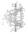
1 to 4 show an
[0024]
More specifically, the first mounting
[0025]
Here, first, the main rubber inner metal fitting 18 constituting the first integral vulcanization molded
[0026]
Furthermore, the main rubber outer
[0027]
The main rubber
[0028]
On the other hand, the diaphragm inner metal fitting 20 constituting the second integrally vulcanized molded
[0029]
Further, the diaphragm outer tube fitting 24 has a thin-walled large-diameter cylindrical shape, and a mounting
[0030]
A diaphragm
[0031]
The
[0032]
Here, the
[0033]
In addition, the
[0034]
Furthermore, the abutment scheduled
[0035]
In the present embodiment, a part of the outer peripheral edge of the annular
[0036]
Thus, the second integral vulcanized molded
[0037]
That is, the diaphragm inner metal fitting 20 is directly superimposed on the upper surface of the main rubber inner metal fitting 18, and the fitting
[0038]
As shown in FIGS. 1 and 2, in a state where the main rubber
[0039]
On the other hand, the diaphragm outer
[0040]
As a result, the
[0041]
Further, the diaphragm outer tube fitting 24, the main rubber outer tube fitting 22 and the cover plate fitting 26 assembled to each other in this manner are caulked and fixed to each other to constitute the second mounting fitting 14. The mounting
[0042]
Further, as described above, the lower end opening of the second mounting
[0043]
The main rubber
[0044]
Further, in the
[0045]
Although the
[0046]
In particular, in the present embodiment, the first mounting
[0047]
In the
[0048]
Thus, under such a mounting state, relative pressure induced between the
[0049]
Therefore, in the
[0050]
In addition, since the
[0051]
Further, since the
[0052]
That is, if the entire abutting
[0053]
As mentioned above, although one embodiment of the present invention has been described in detail, this is merely an example, and the present invention is not construed as being limited in any way by the specific description in the embodiment. The present invention can be carried out in a mode in which various changes, corrections, improvements, etc. are added based on the knowledge of the trader, and any of such embodiments does not depart from the gist of the present invention. Needless to say, it is included in the range.
[0054]
For example, in the above-described embodiment, the contact-scheduled
[0055]
Further, in the above embodiment, the
[0056]
In the above-described embodiment, a so-called passive vibration isolator that obtains a vibration isolating effect by utilizing the fact that pressure fluctuation and flow are passively generated with respect to the sealed fluid by the input vibration. One specific example of applying the present invention is shown. However, as described in Patent Document 1 and the like, the present invention is provided with an actuator to activate pressure fluctuation of an enclosed incompressible fluid. The present invention can be similarly applied to an active vibration isolator in which the vibration isolating characteristic is changed and set by controlling automatically or the vibration is reduced in an offset manner.
[0057]
In addition, in each of the above embodiments, the case where the present invention is applied to an engine mount for automobiles has been described. The same applies to the apparatus.
[0058]
【The invention's effect】
As is apparent from the above description, in the fluid filled type vibration damping device structured according to the present invention, the expansion in the rubber elastic film constituting the wall portion of the equilibrium chamber is ensured while ensuring the variable volume in the equilibrium chamber. The amount of deformation can be effectively suppressed while avoiding stress and concentration of deformation, which can advantageously avoid a decrease in durability due to interference with other members of the rubber elastic membrane. It becomes.
[Brief description of the drawings]
FIG. 1 is a longitudinal sectional view of an engine mount as a first embodiment of the present invention, corresponding to a cross section taken along line II in FIG.
2 is a view showing a longitudinal section different from that of FIG. 1 of the engine mount shown in FIG. 1, and corresponds to a section taken along line II-II in FIG. 3;
3 is a plan view showing a first integrally vulcanized molded product constituting the engine mount shown in FIG. 1. FIG.
4 is a plan view showing a second integrally vulcanized molded product constituting the engine mount shown in FIG. 1. FIG.
5 is a front view of the engine mount shown in FIG. 1, and is a view taken along the line V-V in FIG. 4;
6 is an explanatory view showing a state where the diaphragm bulges and deforms when the engine mount shown in FIG. 1 is mounted. FIG.
[Explanation of symbols]
10 Engine mount
12 First mounting bracket
14 Second mounting bracket
16 Body rubber elastic body
67 Planned contact part
69 Annular thick part
71 Inside area
73 Center thick part
74 Bracket
76 Pressure receiving chamber
78 Balance room
80 Orifice passage
Claims (6)
前記可撓性膜をゴム弾性膜にて構成すると共に、該ゴム弾性膜を環状に厚肉として環状肉厚部を形成し、更に該環状肉厚部で囲まれた部分の略中央において該環状肉厚部から独立して厚肉の中央肉厚部を形成したことを特徴とする流体封入式防振装置。The main body rubber elastic body connects the first mounting member attached to one member to be anti-vibration connected and the second attachment member attached to the other member to be anti-vibration connected, while a part of the wall portion is A pressure receiving chamber made of a rubber elastic body and subjected to pressure fluctuation upon vibration input, and an equilibrium chamber in which a part of the wall portion is made of a flexible film and volume change is allowed, and these pressure receiving chambers A fluid-filled vibration isolator in which an incompressible fluid is sealed in an equilibrium chamber and the pressure receiving chamber and the equilibrium chamber are connected to each other by an orifice passage.
The flexible film is formed of a rubber elastic film, and the rubber elastic film is annularly thickened to form an annular thick portion, and the annular film is formed at the approximate center of the portion surrounded by the annular thick portion. A fluid-filled type vibration damping device, wherein a thick central thick part is formed independently of the thick part.
Priority Applications (2)
| Application Number | Priority Date | Filing Date | Title |
|---|---|---|---|
| JP2003024383A JP4055591B2 (en) | 2003-01-31 | 2003-01-31 | Fluid filled vibration isolator |
| US10/769,089 US7168692B2 (en) | 2003-01-31 | 2004-01-30 | Fluid filled vibration damping device whose flexible layer having thick walled portion |
Applications Claiming Priority (1)
| Application Number | Priority Date | Filing Date | Title |
|---|---|---|---|
| JP2003024383A JP4055591B2 (en) | 2003-01-31 | 2003-01-31 | Fluid filled vibration isolator |
Publications (2)
| Publication Number | Publication Date |
|---|---|
| JP2004232803A true JP2004232803A (en) | 2004-08-19 |
| JP4055591B2 JP4055591B2 (en) | 2008-03-05 |
Family
ID=32952931
Family Applications (1)
| Application Number | Title | Priority Date | Filing Date |
|---|---|---|---|
| JP2003024383A Expired - Fee Related JP4055591B2 (en) | 2003-01-31 | 2003-01-31 | Fluid filled vibration isolator |
Country Status (2)
| Country | Link |
|---|---|
| US (1) | US7168692B2 (en) |
| JP (1) | JP4055591B2 (en) |
Cited By (2)
| Publication number | Priority date | Publication date | Assignee | Title |
|---|---|---|---|---|
| JP2007270890A (en) * | 2006-03-30 | 2007-10-18 | Tokai Rubber Ind Ltd | Fluid-sealed type vibration control device |
| US7413174B2 (en) * | 2005-03-29 | 2008-08-19 | Tokai Rubber Industries, Ltd. | Fluid-filled type vibration-damping device |
Families Citing this family (6)
| Publication number | Priority date | Publication date | Assignee | Title |
|---|---|---|---|---|
| JP4277316B2 (en) * | 2005-03-30 | 2009-06-10 | 東海ゴム工業株式会社 | Vibration isolator |
| JP5051915B2 (en) * | 2008-10-28 | 2012-10-17 | 東海ゴム工業株式会社 | Fluid filled vibration isolator |
| JP5909077B2 (en) * | 2011-11-08 | 2016-04-26 | 東洋ゴム工業株式会社 | Anti-vibration unit |
| CN102705425B (en) * | 2012-06-13 | 2015-03-11 | 宁波拓普集团股份有限公司 | Novel hydraulic suspending outer cover |
| KR20170109160A (en) | 2016-03-18 | 2017-09-28 | 현대자동차주식회사 | Fastening structure of engine-mount |
| US11448285B2 (en) * | 2018-03-12 | 2022-09-20 | Vibracoustic Se | Membrane and hydraulically damping mount |
Family Cites Families (11)
| Publication number | Priority date | Publication date | Assignee | Title |
|---|---|---|---|---|
| US4401298A (en) * | 1980-11-18 | 1983-08-30 | Imperial Clevite Inc. | Flexible column viscous spring damper |
| DE3537865A1 (en) * | 1985-10-24 | 1987-05-07 | Lemfoerder Metallwaren Ag | TWO-CHAMBER SUPPORT BEARING WITH HYDRAULIC DAMPING |
| DE3614161A1 (en) * | 1986-04-26 | 1987-11-05 | Lemfoerder Metallwaren Ag | TWO CHAMBER SUPPORT BEARINGS WITH HYDRAULIC DAMPING, IN PARTICULAR ENGINE BEARINGS IN MOTOR VEHICLES |
| US4997169A (en) * | 1988-08-03 | 1991-03-05 | Honda Giken Kogyo Kabushiki Kaisha | Hydraulically damped mount |
| US5040774A (en) * | 1990-04-09 | 1991-08-20 | The Pullman Company | Hydraulic damping bushing |
| JP2567543B2 (en) | 1992-03-27 | 1996-12-25 | 鬼怒川ゴム工業株式会社 | Liquid-filled anti-vibration mount |
| US5927698A (en) * | 1996-07-24 | 1999-07-27 | Toyoda Gosei Co., Ltd. | Liquid sealed-type vibration insulating device |
| JP2000274480A (en) | 1999-03-24 | 2000-10-03 | Tokai Rubber Ind Ltd | Fluid sealed vibration isolating device |
| US6250615B1 (en) * | 1999-03-31 | 2001-06-26 | Freudenberg-Nok General Partnership | Vibration isolator with a tension restraint |
| JP2001059540A (en) | 1999-08-20 | 2001-03-06 | Nok Vibracoustic Kk | Active mount |
| JP3849534B2 (en) * | 2002-01-29 | 2006-11-22 | 東海ゴム工業株式会社 | Fluid filled vibration isolator |
-
2003
- 2003-01-31 JP JP2003024383A patent/JP4055591B2/en not_active Expired - Fee Related
-
2004
- 2004-01-30 US US10/769,089 patent/US7168692B2/en not_active Expired - Lifetime
Cited By (3)
| Publication number | Priority date | Publication date | Assignee | Title |
|---|---|---|---|---|
| US7413174B2 (en) * | 2005-03-29 | 2008-08-19 | Tokai Rubber Industries, Ltd. | Fluid-filled type vibration-damping device |
| JP2007270890A (en) * | 2006-03-30 | 2007-10-18 | Tokai Rubber Ind Ltd | Fluid-sealed type vibration control device |
| JP4688036B2 (en) * | 2006-03-30 | 2011-05-25 | 東海ゴム工業株式会社 | Fluid filled vibration isolator |
Also Published As
| Publication number | Publication date |
|---|---|
| US7168692B2 (en) | 2007-01-30 |
| JP4055591B2 (en) | 2008-03-05 |
| US20040183240A1 (en) | 2004-09-23 |
Similar Documents
| Publication | Publication Date | Title |
|---|---|---|
| US7780154B2 (en) | Fluid-filled type engine mount | |
| JP5448928B2 (en) | Fluid filled vibration isolator | |
| JPH0446233A (en) | Fluid seal type mounting device and manufacture thereof | |
| JP3489500B2 (en) | Anti-vibration device | |
| JP2004036780A (en) | Fluid-sealed tubular vibration control device | |
| JP3849534B2 (en) | Fluid filled vibration isolator | |
| JP2000074130A (en) | Liquid encapsulation type vibration control device | |
| JP2505503Y2 (en) | Fluid-filled mounting device | |
| JP2007232207A (en) | Fluid-sealed vibration isolating device and its manufacturing process | |
| JP3915531B2 (en) | Fluid filled anti-vibration mount | |
| JP5431982B2 (en) | Liquid-filled vibration isolator | |
| JP4055591B2 (en) | Fluid filled vibration isolator | |
| JP3729120B2 (en) | Fluid filled vibration isolator | |
| JP4003131B2 (en) | Fluid filled vibration isolator | |
| JP2008185152A (en) | Fluid filled vibration absorbing device and engine mount using the same | |
| JP4236095B2 (en) | Suspended fluid filled anti-vibration mount | |
| JP5510713B2 (en) | Liquid-filled vibration isolator | |
| JP2008232315A (en) | Fluid-sealed type vibration control device | |
| JP4188751B2 (en) | Liquid-filled vibration isolator | |
| JP5396336B2 (en) | Fluid filled vibration isolator | |
| JP5108349B2 (en) | Fluid filled vibration isolator | |
| JP3940090B2 (en) | Fluid filled vibration isolator | |
| JP7460501B2 (en) | Anti-vibration device | |
| JP4019163B2 (en) | Active fluid filled vibration isolator | |
| JP2010032023A (en) | Fluid-filled vibration isolation device |
Legal Events
| Date | Code | Title | Description |
|---|---|---|---|
| A621 | Written request for application examination |
Free format text: JAPANESE INTERMEDIATE CODE: A621 Effective date: 20051117 |
|
| A977 | Report on retrieval |
Free format text: JAPANESE INTERMEDIATE CODE: A971007 Effective date: 20070822 |
|
| A131 | Notification of reasons for refusal |
Free format text: JAPANESE INTERMEDIATE CODE: A131 Effective date: 20070827 |
|
| A521 | Request for written amendment filed |
Free format text: JAPANESE INTERMEDIATE CODE: A523 Effective date: 20071024 |
|
| TRDD | Decision of grant or rejection written | ||
| A01 | Written decision to grant a patent or to grant a registration (utility model) |
Free format text: JAPANESE INTERMEDIATE CODE: A01 Effective date: 20071120 |
|
| A61 | First payment of annual fees (during grant procedure) |
Free format text: JAPANESE INTERMEDIATE CODE: A61 Effective date: 20071203 |
|
| R150 | Certificate of patent or registration of utility model |
Ref document number: 4055591 Country of ref document: JP Free format text: JAPANESE INTERMEDIATE CODE: R150 Free format text: JAPANESE INTERMEDIATE CODE: R150 |
|
| FPAY | Renewal fee payment (event date is renewal date of database) |
Free format text: PAYMENT UNTIL: 20101221 Year of fee payment: 3 |
|
| FPAY | Renewal fee payment (event date is renewal date of database) |
Free format text: PAYMENT UNTIL: 20111221 Year of fee payment: 4 |
|
| FPAY | Renewal fee payment (event date is renewal date of database) |
Free format text: PAYMENT UNTIL: 20121221 Year of fee payment: 5 |
|
| FPAY | Renewal fee payment (event date is renewal date of database) |
Free format text: PAYMENT UNTIL: 20131221 Year of fee payment: 6 |
|
| LAPS | Cancellation because of no payment of annual fees |