JP2004232701A - Combining structure between shaft body and shaft coupling - Google Patents
Combining structure between shaft body and shaft coupling Download PDFInfo
- Publication number
- JP2004232701A JP2004232701A JP2003020772A JP2003020772A JP2004232701A JP 2004232701 A JP2004232701 A JP 2004232701A JP 2003020772 A JP2003020772 A JP 2003020772A JP 2003020772 A JP2003020772 A JP 2003020772A JP 2004232701 A JP2004232701 A JP 2004232701A
- Authority
- JP
- Japan
- Prior art keywords
- shaft
- fitting
- fitted
- coupling
- fitting groove
- Prior art date
- Legal status (The legal status is an assumption and is not a legal conclusion. Google has not performed a legal analysis and makes no representation as to the accuracy of the status listed.)
- Granted
Links
Images


Classifications
-
- F—MECHANICAL ENGINEERING; LIGHTING; HEATING; WEAPONS; BLASTING
- F16—ENGINEERING ELEMENTS AND UNITS; GENERAL MEASURES FOR PRODUCING AND MAINTAINING EFFECTIVE FUNCTIONING OF MACHINES OR INSTALLATIONS; THERMAL INSULATION IN GENERAL
- F16D—COUPLINGS FOR TRANSMITTING ROTATION; CLUTCHES; BRAKES
- F16D1/00—Couplings for rigidly connecting two coaxial shafts or other movable machine elements
- F16D1/06—Couplings for rigidly connecting two coaxial shafts or other movable machine elements for attachment of a member on a shaft or on a shaft-end
- F16D1/08—Couplings for rigidly connecting two coaxial shafts or other movable machine elements for attachment of a member on a shaft or on a shaft-end with clamping hub; with hub and longitudinal key
- F16D1/0852—Couplings for rigidly connecting two coaxial shafts or other movable machine elements for attachment of a member on a shaft or on a shaft-end with clamping hub; with hub and longitudinal key with radial clamping between the mating surfaces of the hub and shaft
- F16D1/0864—Couplings for rigidly connecting two coaxial shafts or other movable machine elements for attachment of a member on a shaft or on a shaft-end with clamping hub; with hub and longitudinal key with radial clamping between the mating surfaces of the hub and shaft due to tangential loading of the hub, e.g. a split hub
-
- F—MECHANICAL ENGINEERING; LIGHTING; HEATING; WEAPONS; BLASTING
- F16—ENGINEERING ELEMENTS AND UNITS; GENERAL MEASURES FOR PRODUCING AND MAINTAINING EFFECTIVE FUNCTIONING OF MACHINES OR INSTALLATIONS; THERMAL INSULATION IN GENERAL
- F16D—COUPLINGS FOR TRANSMITTING ROTATION; CLUTCHES; BRAKES
- F16D1/00—Couplings for rigidly connecting two coaxial shafts or other movable machine elements
- F16D1/10—Quick-acting couplings in which the parts are connected by simply bringing them together axially
- F16D1/108—Quick-acting couplings in which the parts are connected by simply bringing them together axially having retaining means rotating with the coupling and acting by interengaging parts, i.e. positive coupling
- F16D1/116—Quick-acting couplings in which the parts are connected by simply bringing them together axially having retaining means rotating with the coupling and acting by interengaging parts, i.e. positive coupling the interengaging parts including a continuous or interrupted circumferential groove in the surface of one of the coupling parts
-
- F—MECHANICAL ENGINEERING; LIGHTING; HEATING; WEAPONS; BLASTING
- F16—ENGINEERING ELEMENTS AND UNITS; GENERAL MEASURES FOR PRODUCING AND MAINTAINING EFFECTIVE FUNCTIONING OF MACHINES OR INSTALLATIONS; THERMAL INSULATION IN GENERAL
- F16D—COUPLINGS FOR TRANSMITTING ROTATION; CLUTCHES; BRAKES
- F16D3/00—Yielding couplings, i.e. with means permitting movement between the connected parts during the drive
- F16D3/16—Universal joints in which flexibility is produced by means of pivots or sliding or rolling connecting parts
- F16D3/26—Hooke's joints or other joints with an equivalent intermediate member to which each coupling part is pivotally or slidably connected
- F16D3/38—Hooke's joints or other joints with an equivalent intermediate member to which each coupling part is pivotally or slidably connected with a single intermediate member with trunnions or bearings arranged on two axes perpendicular to one another
- F16D3/382—Hooke's joints or other joints with an equivalent intermediate member to which each coupling part is pivotally or slidably connected with a single intermediate member with trunnions or bearings arranged on two axes perpendicular to one another constructional details of other than the intermediate member
- F16D3/387—Fork construction; Mounting of fork on shaft; Adapting shaft for mounting of fork
-
- Y—GENERAL TAGGING OF NEW TECHNOLOGICAL DEVELOPMENTS; GENERAL TAGGING OF CROSS-SECTIONAL TECHNOLOGIES SPANNING OVER SEVERAL SECTIONS OF THE IPC; TECHNICAL SUBJECTS COVERED BY FORMER USPC CROSS-REFERENCE ART COLLECTIONS [XRACs] AND DIGESTS
- Y10—TECHNICAL SUBJECTS COVERED BY FORMER USPC
- Y10T—TECHNICAL SUBJECTS COVERED BY FORMER US CLASSIFICATION
- Y10T403/00—Joints and connections
- Y10T403/16—Joints and connections with adjunctive protector, broken parts retainer, repair, assembly or disassembly feature
- Y10T403/1608—Holding means or protector functioning only during transportation, assembly or disassembly
-
- Y—GENERAL TAGGING OF NEW TECHNOLOGICAL DEVELOPMENTS; GENERAL TAGGING OF CROSS-SECTIONAL TECHNOLOGIES SPANNING OVER SEVERAL SECTIONS OF THE IPC; TECHNICAL SUBJECTS COVERED BY FORMER USPC CROSS-REFERENCE ART COLLECTIONS [XRACs] AND DIGESTS
- Y10—TECHNICAL SUBJECTS COVERED BY FORMER USPC
- Y10T—TECHNICAL SUBJECTS COVERED BY FORMER US CLASSIFICATION
- Y10T403/00—Joints and connections
- Y10T403/32—Articulated members
- Y10T403/32008—Plural distinct articulation axes
- Y10T403/32041—Universal
-
- Y—GENERAL TAGGING OF NEW TECHNOLOGICAL DEVELOPMENTS; GENERAL TAGGING OF CROSS-SECTIONAL TECHNOLOGIES SPANNING OVER SEVERAL SECTIONS OF THE IPC; TECHNICAL SUBJECTS COVERED BY FORMER USPC CROSS-REFERENCE ART COLLECTIONS [XRACs] AND DIGESTS
- Y10—TECHNICAL SUBJECTS COVERED BY FORMER USPC
- Y10T—TECHNICAL SUBJECTS COVERED BY FORMER US CLASSIFICATION
- Y10T403/00—Joints and connections
- Y10T403/32—Articulated members
- Y10T403/32606—Pivoted
- Y10T403/32861—T-pivot, e.g., wrist pin, etc.
- Y10T403/32893—T-pivot, e.g., wrist pin, etc. including distinct pin retainer
- Y10T403/32901—Unitary clip or plug
Landscapes
- Engineering & Computer Science (AREA)
- General Engineering & Computer Science (AREA)
- Mechanical Engineering (AREA)
- Steering Controls (AREA)
- Snaps, Bayonet Connections, Set Pins, And Snap Rings (AREA)
- Clamps And Clips (AREA)
Abstract
Description
【0001】
【発明の属する技術分野】
本発明は軸体と軸継手との結合構造に関する。
【0002】
【従来の技術】
車両におけるステアリング装置は、その一端が操舵輪に繋がる操舵軸と、該操舵軸の他端に結合された軸継手をその一端に有する伝動軸と、該伝動軸の他端に軸継手を介して結合され、車体の左右方向に延設されたラック軸の中途部に噛合するピニオンを有するピニオン軸とを備えている。
【0003】
操舵軸又はピニオン軸からなる軸体と軸継手との結合構造は、例えば、特許文献1に記載されている。
特許文献1の結合構造において、軸体の端部は円形周面の一部に一対の平行な平取面及び該平取面にその両端が臨む抜止溝を有する非円形の嵌合部が設けられている。軸継手は前記嵌合部が相対回転不能に嵌合される嵌合溝及び該嵌合溝に臨む同芯的な2つの孔を有しており、この孔の1つに鍔を有するナット部材が圧入されている。また、軸継手の外周りには前記各孔に対応する貫通孔を有する湾曲部、及び該湾曲部の一端に連なり前記嵌合溝内へ挿入される規制片を有する板体が保持されている。この板体は反規制片側の孔周りを被挾着部とし、前記ナット部材を前記貫通孔の1つに圧入することにより前記鍔と軸継手との間で被挾着部を挾着してある。
【0004】
軸体と軸継手との結合は、軸体の嵌合部を軸継手の嵌合溝に該嵌合溝の深さ方向端縁側から挿入して嵌合し、板体の貫通孔及び軸継手の孔と抜止溝とにボルトを挿入し、該ボルトを前記ナット部材に締め込むことにより軸長方向の相対移動及び相対回転を不能に結合される。この場合、嵌合部の嵌合溝への挿入に伴って板体の規制片が撓み、嵌合部が嵌合溝に嵌合された後、規制片が弾性復元して嵌合部の一側に当接し、嵌合部の反挿入方向への移動を規制する。
【0005】
【特許文献1】
特開2000−310232号公報
【0006】
【発明が解決しようとする課題】
ところが、以上のように構成された結合構造は扁平とした被挾着部を挾着することにより板体を軸継手に固定しているため、板体の固定力が十分でなく、板体がガタつくことになり、改善策が要望されていた。ところで、板体の固定力を高めるには、板体を溶接又はかしめにより固定することが考えられるが、何れも特殊な固定手法であるため、作業性が悪く、コスト高になる。
【0007】
本発明は斯かる事情に鑑みてなされたものであり、特殊な固定手法を採用することなく板体の固定力を簡易に高めることができる軸体と軸継手との結合構造を提供することを目的とする。
【0008】
【課題を解決するための手段】
第1発明に係る軸体と軸継手との結合構造は、軸体と、該軸体が嵌合される嵌合溝、該嵌合溝に臨む2つの孔を有する軸継手本体、及び前記孔の1つに圧入された係止体を備える軸継手とを、前記孔に挿入して前記係止体に係止する結合軸により結合する結合構造において、前記軸体の移動を規制する規制片、該規制片に連なり前記係止体と軸継手本体との間で挾着された被挾着部及び該被挾着部に突設された凸部を有する板体を備えており、前記軸継手本体及び/又は係止体は前記凸部が嵌入された凹部を有することを特徴とする。
【0009】
第1発明にあっては、係止体を軸継手本体の孔に圧入することにより、板体の被挾着部に突設された凸部を軸継手本体及び/又は係止体の凹部に嵌入させることができるため、板体のガタつきをなくすることができ、板体の固定力を高めることができる。
【0010】
第2発明に係る軸体と軸継手との結合構造は、前記凸部は前記軸継手本体及び/又は係止体よりも硬度を高くしてあることを特徴とする。
第2発明にあっては、係止体を軸継手本体の孔に圧入することにより、板体の被挾着部に突設された凸部を軸継手本体及び/又は係止体に食い込ませることができるため、予め凹部を設けることなく板体のガタつきをなくすることができる。
【0011】
【発明の実施の形態】
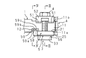
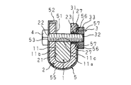
以下本発明をその実施の形態を示す図面に基づいて詳述する。図1は本発明に係る結合構造の分解斜視図、図2は平面図、図3は図2のIII −III 線の断面図、図4は図2のIV−IV線の断面図である。
【0012】
この結合構造は、その一端部に非円形の嵌合部11を有する軸体1と、嵌合部11が相対回転不能に嵌合される嵌合溝21及び該嵌合溝21に臨む2つの孔22,23を有する軸継手本体2、及び孔23に圧入された係止体3を備える軸継手Aとを、孔22,23に挿入して係止体3に係止する結合軸4により結合するものであり、係止体3と軸継手本体2との間に板体5が挾着されている。
【0013】
軸体1の一端部は円形周面の一部に一対の平行な平取面11a,11b及び該平取面11a,11bにその両端が臨む半円形の抜止溝11cを有する非円形の嵌合部11と、該嵌合部11の一方の平取面11aに連なり、該平取面11aよりも平取り深さが深い位置決め凹所12とが設けられている。
【0014】
軸継手本体2は嵌合溝21及び該嵌合溝21に臨む同芯的な2つの孔22,23を有する断面略U字形の継部24と、該継部24に連なり同芯的な2つの貫通孔(図示せず)を有するヨーク25とを備えている。
【0015】
軸継手本体2の嵌合溝21の一側面で深さ方向の端縁側には側面よりも深い2つの退避凹所26,26が設けられている。この退避凹所26,26は嵌合溝21の長手方向両端近傍から孔22の近傍にかけて設けられている。尚、軸継手本体2は例えば炭素鋼からなる。
【0016】
係止体3は圧入筒部31と、該圧入筒部31に連なり、ねじ孔32を有する鍔部33とを有しており、圧入筒部31が孔23に圧入され、鍔部33が継部24の外側へ突出している。尚、係止体3は例えば構造用鋼からなる。
【0017】
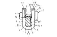
図5は板体の斜視図である。
板体5は軸継手本体2及び係止体3よりも硬度が高いばね鋼からなり、嵌合溝21内で軸体1の反挿入方向への移動を規制する2つの規制片51,51と、該規制片51,51に屈曲部52を介して連なり孔22,23に対応する貫通孔53,54が穿設された略U字形の湾曲部55とを備え、該湾曲部55の貫通孔54部分を、圧入筒部31の圧入により継部24と鍔部33との間で挾着される被挾着部56としてある。この被挾着部56には挾着される方向、換言すれば板厚方向内側へ突設された凸部57を有する。尚、湾曲部55は両端部間の間隔を継部24の幅寸法よりも大きくし、結合軸4の締込力により撓むようにしてある。
【0018】
凸部57は貫通孔54の周方向に離隔した4つの位置に2つの切溝を平行的に設け、各切溝間の部片を板厚方向内側へ曲げることにより形成されており、継部24と鍔部33との間で挾着されるとき凸部57が継部24に食い込み、継部24に凹部27ができるようにしてある。
【0019】
規制片51,51はその先端が嵌合部11の反嵌合方向側部分に当接することにより軸体1の反挿入方向への移動を規制するもので、嵌合溝21の長手方向に離隔し、退避凹所26,26と向き合っており、途中から先端縁にかけて湾曲部55の一端側へ傾斜している。
【0020】
また、板体5には被挾着部56の近傍に屈曲部58を介して連なり嵌合溝21の長手方向外側に配置されて軸体1の位置決め凹所12に係合し、嵌合溝21の幅方向への撓みを可能とした可撓部材59が設けられている。
【0021】
この可撓部材59は嵌合部11の嵌合溝21の正確な位置に嵌合されていない状態で嵌合部11が嵌合溝21に嵌合されるのを防ぐもので、屈曲部58に連なる広幅部59aと該広幅部59aに連なり広幅部59aよりも狭い幅としてある狭幅部59bとを有しており、該狭幅部59bを嵌合溝21の幅方向外側へ撓ませるようにしてある。この狭幅部59bは、その先端部を嵌合溝21の幅方向外側へ曲げてあり、該狭幅部59bの先端部に指等を引掛け易いようにしてある。
【0022】
また、可撓部材59は嵌合溝21の他側面よりも内側となるように配置されており、嵌合量が不足して正確な位置に嵌合されていない状態で嵌合部11が嵌合溝21に嵌合される場合、嵌合部11が広幅部59aの端縁に当接し、嵌合部11が嵌合溝21に嵌合されないようにし、正確な位置で嵌合している場合には位置決め凹所12に可撓部材59が挿入され、狭幅部59bが位置決め凹所12と係合するようにしてある。
【0023】
広幅部59aの一部は嵌合溝21の他側面と向き合う撓み規制部59cとしてあり、嵌合量が不足して正確な位置に嵌合されていない場合に、嵌合部11が広幅部59aの端縁に当接したとき、撓み規制部59cが嵌合溝21の側面に当接し、狭幅部59bの撓みを規制するようにしてある。また、広幅部59aは嵌合溝21に嵌合部11が嵌合されている場合に嵌合部11と当接しない位置に設けられており、狭幅部59bを撓ませて狭幅部59bの位置決め凹所12との係合を解除し、軸体1を嵌合溝21の長手方向へ引き抜く場合、嵌合部11が広幅部59aに当接しないようにしてある。
【0024】
図6はステアリング装置に用いた例を示す模式図である。
以上のように構成された結合構造は、例えばステアリング装置Bに用いられる。このステアリング装置Bは、一端が舵取りのための操舵輪100に繋がる操舵軸101と、その一端が操舵軸101の他端に軸継手Aを介して結合された伝動軸102と、該伝動軸102の他端に軸継手Aを介して結合され、車体の左右方向に延設されたラック軸(図示せず)の中途部に噛合するピニオン(図示せず)を有するピニオン軸103とを備えている。
【0025】
以上の構成において、板体5を軸継手本体2に結合する場合、板体5の湾曲部55を継部24に嵌め込み、係止体3の圧入筒部31を被挾着部56の貫通孔54から継部24の孔23に圧入することにより被挾着部56を継部24と鍔部33との間で挾着するのであり、圧入するときの圧入力により被挾着部56の凸部57を継部24に食い込ませる。この凸部57の食い込みにより継部24に凹部27が発生し、該凹部27に凸部57が嵌入された状態となる。従って、板体5のガタ付きを阻止することができ、板体5をガタ付きがない状態で挾着することができる。このように板体5が固定された場合、規制片51,51は継部24の退避凹所26,26側へ退避している。
【0026】
軸体1と軸継手Aとを結合する場合、軸体1の嵌合部11を嵌合溝21の深さ方向の端縁側から嵌合溝21内に挿入して嵌合する。また、嵌合部11の嵌合溝21への嵌合量が充足して正確な位置に嵌合している場合、位置決め凹所12が可撓部材59と向き合うことになり、嵌合部11の嵌合溝21への嵌合量が不足して正確な位置に嵌合されていない場合、位置決め凹所12が可撓部材59に対して嵌合溝21の長手方向へ離隔した状態となる。
【0027】
嵌合量が充足して正確な位置に嵌合している場合、嵌合部11の嵌合溝21への挿入に伴って規制片51,51が撓み、該規制片51,51が退避凹所26,26へ退避するとともに、可撓部材59の狭幅部59bが位置決め凹所12に挿入され、嵌合部11を嵌合溝21に嵌合することができる。この嵌合により抜止溝11cが孔22,23と向き合う。しかる後、孔22から係止体3のねじ孔32へボルトからなる結合軸4を挿入し、締め込むことにより嵌合部11を嵌合溝21内に固定する。この固定により、軸体1の相対回転が阻止されるとともに、軸体1の軸長方向への抜き出しが阻止される。また、板体5の湾曲部55の一側部分が結合軸4の頭部により挾圧され、規制片51,51が嵌合溝21の内側へ変位し、該規制片51,51の先端が嵌合部11の反挿入方向側部分に当接し、結合軸4を支点とする嵌合部11の揺動を阻止することができる。
【0028】
図7は軸体と嵌合溝との嵌合量が不足して正確な位置に嵌合されていない状態を示す図である。
位置決め凹所12が可撓部材59に対して軸体1の軸長方向へ離隔した状態となり、嵌合量が不足して正確な位置に嵌合されていない場合、嵌合部11が可撓部材59の広幅部59aの端縁に当接し、嵌合溝21への挿入ができない。従って、嵌合量が不足して正確な位置に嵌合されていない状態であることを判断することができ、嵌合量が不足して正確な位置に嵌合されていない状態で結合されることを回避できる。尚、可撓部材59は撓み規制部59cを有するため、嵌合部11が広幅部59aの端縁に当接したとき、撓み規制部59cが嵌合溝21の他側に当接し、可撓部材59の撓みを規制することができ、嵌合部11が嵌合溝21に挿入されるのを確実に阻止することができる。
【0029】
図8は軸体と軸継手との結合を解除する場合の説明図である。
保守点検時など軸体1と軸継手Aとの結合を解除する場合、可撓部材59の狭幅部59bの先端部に指等を引掛け、狭幅部59bを嵌合溝21の幅方向外側へ撓ませることにより、該狭幅部59bが嵌合溝21よりも外側へ変位し、可撓部材59の位置決め凹所12との係合を解除することができ、可撓部材59に邪魔されることなく嵌合部11を軸長方向へ抜き出すことができる。このとき、可撓部材59が有する撓み規制部59cは嵌合部11に当接しない位置に設けられているため、可撓部材59に邪魔されることなく軸体1を嵌合溝21の長手方向へ抜き出すことができる。
【0030】
尚、以上説明した実施の形態では、被挾着部56の貫通孔54に切溝を設け、該切溝の間の部片を折り曲げることにより凸部57を形成したが、その他、凸部57は貫通孔54と離隔した位置に略コ字形の切溝を設け、該切溝の間の部片を折り曲げることにより形成してもよいし、また、切溝を設けることなく成形により突設してもよい。また、凸部57は板厚方向内側へ突出する構成としたが、その他、板厚方向外側へ突出する構成とし、係止体3の圧入力により係止体3の鍔部33に食い込ませるようにしてもよいし、また、板厚方向両側へ突出する構成とし、係止体3の圧入力により継部24及び鍔部33に食い込ませるようにしてもよい。また、凸部57は係止体3の圧入力により継部24及び/又は鍔部33に食い込ませる他、凸部57が挿入される凹部27を継部24及び/又は鍔部33に予め形成し、係止体3の圧入力により凸部57を凹部27に嵌入するようにしてもよい。
【0031】
また、以上説明した実施の形態では、ばね鋼からなる板体を用いることにより、凸部57をの硬度を軸継手本体2及び係止体3の硬度よりも高くしたが、その他、軸継手本体2及び係止体3の硬度以下の硬度を有する板体を用い、少なくとも凸部57部分を焼き入れ等の表面処理を施すことにより凸部57の硬度を軸継手本体2及び係止体3の硬度よりも高くしてもよい。
【0032】
【発明の効果】
以上詳述したように第1発明によれば、板体のガタつきをなくすることができ、板体の固定力を高めることができる。
【0033】
第2発明によれば、予め凹部を設けることなく板体のガタつきをなくすることができる。
【図面の簡単な説明】
【図1】本発明に係る結合構造の分解斜視図である。
【図2】本発明に係る結合構造の平面図である。
【図3】図2のIII −III 線の断面図である。
【図4】図2のIV−IV線の断面図である。
【図5】本発明に係る結合構造の板体の斜視図である。
【図6】本発明に係る結合構造をステアリング装置に用いた例を示す模式図である。
【図7】本発明に係る結合構造の軸体と嵌合溝との嵌合量が不足して正確な位置に嵌合されていない状態を示す図である。
【図8】本発明に係る結合構造の軸体と軸継手との結合を解除する場合の説明図である。
【符号の説明】
1 軸体
2 軸継手本体
3 係止体
4 結合軸
5 板体
21 嵌合溝
22,23 孔
27 凹部
51 規制片
56 被挾着部
57 凸部
A 軸継手[0001]
TECHNICAL FIELD OF THE INVENTION
The present invention relates to a coupling structure between a shaft body and a shaft coupling.
[0002]
[Prior art]
A steering device in a vehicle includes a steering shaft having one end connected to a steered wheel, a transmission shaft having at one end a shaft coupling coupled to the other end of the steering shaft, and a shaft coupling at the other end of the transmission shaft. And a pinion shaft having a pinion engaged with a middle part of a rack shaft extending in the left-right direction of the vehicle body.
[0003]
A coupling structure between a shaft body composed of a steering shaft or a pinion shaft and a shaft joint is described in, for example,
In the coupling structure of
[0004]
The coupling between the shaft body and the shaft joint is performed by inserting the fitting portion of the shaft body into the fitting groove of the shaft joint from the depth direction end side of the fitting groove and fitting the same into the through hole of the plate body and the shaft joint. A bolt is inserted into the hole and the retaining groove, and the bolt is tightened into the nut member, so that relative movement and relative rotation in the axial direction cannot be performed. In this case, the restricting piece of the plate body is bent in accordance with the insertion of the fitting portion into the fitting groove, and after the fitting portion is fitted into the fitting groove, the regulating piece elastically recovers and one of the fitting portions is restored. And restricts the movement of the fitting portion in the anti-insertion direction.
[0005]
[Patent Document 1]
JP 2000-310232 A
[Problems to be solved by the invention]
However, in the coupling structure configured as described above, the plate body is fixed to the shaft coupling by clamping the flat clamping portion, so that the fixing force of the plate body is not sufficient, and the plate body is There was rattling, and improvement measures were requested. By the way, in order to increase the fixing force of the plate, it is conceivable to fix the plate by welding or caulking. However, since these are special fixing methods, workability is poor and cost increases.
[0007]
The present invention has been made in view of the above circumstances, and an object of the present invention is to provide a coupling structure between a shaft body and a shaft coupling that can easily increase a fixing force of a plate body without employing a special fixing method. Aim.
[0008]
[Means for Solving the Problems]
A coupling structure of a shaft body and a shaft joint according to a first aspect of the present invention includes a shaft body, a fitting groove in which the shaft body is fitted, a shaft joint body having two holes facing the fitting groove, and the hole. A coupling member having a locking member press-fitted into one of the first and second coupling members connected by a coupling shaft that is inserted into the hole and locked to the locking member. A plate body having a clamped portion connected to the restricting piece and clamped between the locking body and the shaft coupling main body, and a projection protruding from the clamped portion. The joint body and / or the locking body has a concave portion into which the convex portion is fitted.
[0009]
According to the first aspect of the present invention, the protrusion protruding from the clamped portion of the plate is inserted into the hole of the shaft coupling main body and / or the recess of the locking body by press-fitting the locking body into the hole of the shaft coupling main body. Since the plate can be fitted, rattling of the plate can be eliminated, and fixing force of the plate can be increased.
[0010]
The joint structure of the shaft body and the shaft joint according to the second invention is characterized in that the protrusion has a higher hardness than the shaft joint body and / or the locking body.
According to the second aspect of the present invention, by pressing the locking body into the hole of the shaft coupling main body, the projection protruding from the clamped portion of the plate is bitten into the shaft coupling main body and / or the locking body. Therefore, rattling of the plate body can be eliminated without providing a concave portion in advance.
[0011]
BEST MODE FOR CARRYING OUT THE INVENTION
Hereinafter, the present invention will be described in detail with reference to the drawings showing the embodiments. 1 is an exploded perspective view of a coupling structure according to the present invention, FIG. 2 is a plan view, FIG. 3 is a cross-sectional view taken along line III-III of FIG. 2, and FIG. 4 is a cross-sectional view taken along line IV-IV of FIG.
[0012]
This coupling structure includes a
[0013]
One end of the
[0014]
The
[0015]
On one side surface of the
[0016]
The
[0017]
FIG. 5 is a perspective view of the plate.
The
[0018]
The
[0019]
The restricting
[0020]
The
[0021]
The
[0022]
Further, the
[0023]
A part of the wide portion 59a serves as a
[0024]
FIG. 6 is a schematic diagram showing an example used for a steering device.
The coupling structure configured as described above is used for, for example, a steering device B. The steering device B includes a steering shaft 101 having one end connected to a steered
[0025]
In the above configuration, when connecting the
[0026]
When connecting the
[0027]
When the fitting amount is sufficient and the fitting is performed at the correct position, the restricting
[0028]
FIG. 7 is a view showing a state in which the fitting amount between the shaft body and the fitting groove is insufficient and the shaft body is not fitted at an accurate position.
When the
[0029]
FIG. 8 is an explanatory diagram in the case where the coupling between the shaft body and the shaft coupling is released.
When the coupling between the
[0030]
In the embodiment described above, a cut groove is provided in the through
[0031]
Further, in the embodiment described above, the hardness of the
[0032]
【The invention's effect】
As described in detail above, according to the first aspect, the backlash of the plate can be eliminated, and the fixing force of the plate can be increased.
[0033]
According to the second aspect, rattling of the plate body can be eliminated without providing a concave portion in advance.
[Brief description of the drawings]
FIG. 1 is an exploded perspective view of a coupling structure according to the present invention.
FIG. 2 is a plan view of a coupling structure according to the present invention.
FIG. 3 is a sectional view taken along line III-III in FIG. 2;
FIG. 4 is a sectional view taken along line IV-IV of FIG. 2;
FIG. 5 is a perspective view of a plate having a coupling structure according to the present invention.
FIG. 6 is a schematic diagram showing an example in which the coupling structure according to the present invention is used in a steering device.
FIG. 7 is a view showing a state in which the fitting amount between the shaft body and the fitting groove of the coupling structure according to the present invention is insufficient, and the fitting is not performed at an accurate position.
FIG. 8 is an explanatory diagram in a case where the coupling between the shaft body and the shaft coupling of the coupling structure according to the present invention is released.
[Explanation of symbols]
DESCRIPTION OF
Claims (2)
該軸体が嵌合される嵌合溝、該嵌合溝に臨む2つの孔を有する軸継手本体、及び前記孔の1つに圧入された係止体を備える軸継手とを、
前記孔に挿入して前記係止体に係止する結合軸により結合する結合構造において、
前記軸体の移動を規制する規制片、該規制片に連なり前記係止体と軸継手本体との間で挾着された被挾着部及び該被挾着部に突設された凸部を有する板体を備えており、前記軸継手本体及び/又は係止体は前記凸部が嵌入された凹部を有することを特徴とする軸体と軸継手との結合構造。A shaft body,
A fitting groove in which the shaft body is fitted, a shaft coupling body having two holes facing the fitting groove, and a shaft coupling including a locking body press-fitted into one of the holes;
In a coupling structure that is coupled by a coupling shaft that is inserted into the hole and locked to the locking body,
A restricting piece for restricting the movement of the shaft, a clamped portion connected to the restricting piece and clamped between the locking body and the shaft coupling body, and a convex portion protruding from the clamped portion. A coupling structure between a shaft body and a shaft joint, wherein the shaft body and / or the locking body have a concave portion into which the convex portion is fitted.
Priority Applications (5)
| Application Number | Priority Date | Filing Date | Title |
|---|---|---|---|
| JP2003020772A JP4178261B2 (en) | 2003-01-29 | 2003-01-29 | Connection structure of shaft body and shaft coupling |
| US10/765,594 US7241068B2 (en) | 2003-01-29 | 2004-01-26 | Coupling structure of shaft body and shaft joint |
| EP04001707A EP1443232B1 (en) | 2003-01-29 | 2004-01-27 | Coupling structure of shaft body and shaft joint |
| DE602004000087T DE602004000087T2 (en) | 2003-01-29 | 2004-01-27 | Connecting arrangement of shaft body and shaft joint |
| CNB2004100390526A CN100348880C (en) | 2003-01-29 | 2004-01-29 | Connection structure of shaft body and coupling |
Applications Claiming Priority (1)
| Application Number | Priority Date | Filing Date | Title |
|---|---|---|---|
| JP2003020772A JP4178261B2 (en) | 2003-01-29 | 2003-01-29 | Connection structure of shaft body and shaft coupling |
Publications (2)
| Publication Number | Publication Date |
|---|---|
| JP2004232701A true JP2004232701A (en) | 2004-08-19 |
| JP4178261B2 JP4178261B2 (en) | 2008-11-12 |
Family
ID=32652873
Family Applications (1)
| Application Number | Title | Priority Date | Filing Date |
|---|---|---|---|
| JP2003020772A Expired - Fee Related JP4178261B2 (en) | 2003-01-29 | 2003-01-29 | Connection structure of shaft body and shaft coupling |
Country Status (5)
| Country | Link |
|---|---|
| US (1) | US7241068B2 (en) |
| EP (1) | EP1443232B1 (en) |
| JP (1) | JP4178261B2 (en) |
| CN (1) | CN100348880C (en) |
| DE (1) | DE602004000087T2 (en) |
Cited By (1)
| Publication number | Priority date | Publication date | Assignee | Title |
|---|---|---|---|---|
| JP2008032181A (en) * | 2006-07-31 | 2008-02-14 | Toyota Motor Corp | Temporary fastening structure of shaft and yoke |
Families Citing this family (8)
| Publication number | Priority date | Publication date | Assignee | Title |
|---|---|---|---|---|
| JP5176349B2 (en) * | 2007-03-15 | 2013-04-03 | 日本精工株式会社 | Steering device |
| KR101268274B1 (en) * | 2009-06-30 | 2013-05-31 | 주식회사 만도 | Steering Column for Vehicle |
| DE102010044495B4 (en) * | 2009-09-07 | 2014-07-03 | Mando Corporation | Steering column for a vehicle |
| US8328648B2 (en) * | 2010-11-23 | 2012-12-11 | Steering Solutions Ip Holding Corporation | Cardan joint assembly and a cardan joint protector device |
| FR2979403B1 (en) * | 2011-08-31 | 2014-02-14 | Zf Systemes De Direction Nacam Sas | DEVICE FOR CONNECTING A STEERING COLUMN WITH A DIRECTION HOUSING. |
| CN106218706A (en) * | 2016-08-25 | 2016-12-14 | 江苏金也汽车配件有限公司 | A kind of motor turning lower drive shaft assembly of non-welding structure |
| US11739794B2 (en) * | 2018-11-01 | 2023-08-29 | Steering Solutions Ip Holding Corporation | Clamp yoke error proofing device and method |
| US20220095471A1 (en) * | 2020-09-21 | 2022-03-24 | Dell Products L.P. | Systems and methods for universal clamping of information handling resource |
Family Cites Families (15)
| Publication number | Priority date | Publication date | Assignee | Title |
|---|---|---|---|---|
| FR2625538B1 (en) | 1987-12-31 | 1991-08-16 | Nacam | COUPLING DEVICE AND ITS APPLICATION IN PARTICULAR TO AN AUTOMOTIVE STEERING |
| FR2686130B1 (en) * | 1992-01-10 | 1994-11-10 | Nacam | FIXING DEVICE WITH A RETRACTABLE AXIAL GUIDE STOP. |
| DE4202684C1 (en) * | 1992-01-31 | 1993-07-29 | Etablissement Supervis, Vaduz, Li | |
| JPH08326767A (en) * | 1995-05-26 | 1996-12-10 | Nippon Seiko Kk | Combining part of shaft with yoke of universal joint |
| JPH09296810A (en) * | 1996-04-30 | 1997-11-18 | Toyota Motor Corp | Shaft fixing structure |
| US6155739A (en) * | 1997-07-02 | 2000-12-05 | Nsk Ltd. | Temporary connection device for universal joint |
| JP3843610B2 (en) * | 1997-07-02 | 2006-11-08 | 日本精工株式会社 | York clip |
| JPH1130241A (en) * | 1997-07-08 | 1999-02-02 | Nippon Seiko Kk | Yoke clip |
| FR2771143A1 (en) * | 1997-11-17 | 1999-05-21 | Ecia Equip Composants Ind Auto | Mounting of a shaft end into a fork end for a vehicle steering column |
| JP3646556B2 (en) | 1998-06-11 | 2005-05-11 | 日本精工株式会社 | Elastic shaft coupling |
| JP3801809B2 (en) * | 1999-04-27 | 2006-07-26 | 株式会社ジェイテクト | Shaft and yoke coupling structure |
| JP2000320562A (en) | 1999-05-14 | 2000-11-24 | Koyo Seiko Co Ltd | Combination structure of shaft and yoke |
| JP3833021B2 (en) * | 1999-09-29 | 2006-10-11 | 株式会社ジェイテクト | Universal joint |
| FR2802590B1 (en) * | 1999-12-16 | 2002-07-19 | Delphi Tech Inc | DEVICE FOR RECEIVING A TIGHTENING SCREW IN PARTICULAR FROM A CARDAN JOINT JAW ON A STEERING SHAFT OF A STEERING COLUMN |
| FR2815924B1 (en) | 2000-10-27 | 2003-01-24 | Nacam | DEVICE FOR ASSEMBLING A STEERING COLUMN BRACKET WITH A DIRECTION PINION OF A MOTOR VEHICLE |
-
2003
- 2003-01-29 JP JP2003020772A patent/JP4178261B2/en not_active Expired - Fee Related
-
2004
- 2004-01-26 US US10/765,594 patent/US7241068B2/en not_active Expired - Lifetime
- 2004-01-27 EP EP04001707A patent/EP1443232B1/en not_active Expired - Lifetime
- 2004-01-27 DE DE602004000087T patent/DE602004000087T2/en not_active Expired - Lifetime
- 2004-01-29 CN CNB2004100390526A patent/CN100348880C/en not_active Expired - Fee Related
Cited By (2)
| Publication number | Priority date | Publication date | Assignee | Title |
|---|---|---|---|---|
| JP2008032181A (en) * | 2006-07-31 | 2008-02-14 | Toyota Motor Corp | Temporary fastening structure of shaft and yoke |
| JP4661724B2 (en) * | 2006-07-31 | 2011-03-30 | トヨタ自動車株式会社 | Temporary fastening structure of shaft and yoke |
Also Published As
| Publication number | Publication date |
|---|---|
| DE602004000087T2 (en) | 2006-06-14 |
| US20040156670A1 (en) | 2004-08-12 |
| EP1443232B1 (en) | 2005-09-14 |
| CN1519483A (en) | 2004-08-11 |
| DE602004000087D1 (en) | 2005-10-20 |
| CN100348880C (en) | 2007-11-14 |
| EP1443232A1 (en) | 2004-08-04 |
| JP4178261B2 (en) | 2008-11-12 |
| US7241068B2 (en) | 2007-07-10 |
Similar Documents
| Publication | Publication Date | Title |
|---|---|---|
| JP2004278698A (en) | Coupling structure between shaft body and shaft coupling | |
| US7461996B2 (en) | Erroneous assembling preventing tool for universal joint and universal joint | |
| JP5170520B2 (en) | Misassembly prevention tool and universal joint including the same | |
| US7597500B2 (en) | Arrangement for assembling two parts by screw-fastening using a screw-nut system | |
| JP2004232701A (en) | Combining structure between shaft body and shaft coupling | |
| JP5217861B2 (en) | Connecting structure and steering device | |
| JPWO2008015741A1 (en) | Universal joint yoke | |
| JP2001193734A (en) | Fixing method for spherical slide bearing | |
| JP2007303480A (en) | Joining structure of yoke and shaft of universal joint | |
| JP3658855B2 (en) | Joint between shaft and universal joint yoke | |
| US10738833B2 (en) | Yoke to shaft attachment assembly | |
| JP2007239836A (en) | Connecting structure of shaft and yoke of universal joint | |
| JP6642551B2 (en) | Torque transmission shaft | |
| JP3843610B2 (en) | York clip | |
| JP2010084897A (en) | Joint, and joining method of joint and shaft | |
| JP4178317B2 (en) | Connection structure of universal joint and shaft | |
| JP2007232223A (en) | Connecting portion of shaft and yoke of universal joint | |
| JP2018100715A (en) | Coupling structure of shaft and yoke | |
| WO2019049882A1 (en) | Torque transmission shaft | |
| JP2005042760A (en) | Bonding structure of shaft and yoke | |
| JP3226581U (en) | Link structure | |
| JP2012193798A (en) | Coupling structure for shaft and yoke of universal joint, and vehicle steering apparatus | |
| JP4134938B2 (en) | Joint between shaft and universal joint yoke | |
| JP2003181938A (en) | Mounting structure for resin member | |
| JP2007263313A (en) | Connecting structure of yoke and shaft of universal joint |
Legal Events
| Date | Code | Title | Description |
|---|---|---|---|
| A621 | Written request for application examination |
Free format text: JAPANESE INTERMEDIATE CODE: A621 Effective date: 20050926 |
|
| A977 | Report on retrieval |
Free format text: JAPANESE INTERMEDIATE CODE: A971007 Effective date: 20080121 |
|
| A131 | Notification of reasons for refusal |
Free format text: JAPANESE INTERMEDIATE CODE: A131 Effective date: 20080122 |
|
| A521 | Request for written amendment filed |
Free format text: JAPANESE INTERMEDIATE CODE: A523 Effective date: 20080324 |
|
| TRDD | Decision of grant or rejection written | ||
| A01 | Written decision to grant a patent or to grant a registration (utility model) |
Free format text: JAPANESE INTERMEDIATE CODE: A01 Effective date: 20080722 |
|
| A01 | Written decision to grant a patent or to grant a registration (utility model) |
Free format text: JAPANESE INTERMEDIATE CODE: A01 |
|
| A61 | First payment of annual fees (during grant procedure) |
Free format text: JAPANESE INTERMEDIATE CODE: A61 Effective date: 20080804 |
|
| R150 | Certificate of patent or registration of utility model |
Ref document number: 4178261 Country of ref document: JP Free format text: JAPANESE INTERMEDIATE CODE: R150 Free format text: JAPANESE INTERMEDIATE CODE: R150 |
|
| FPAY | Renewal fee payment (event date is renewal date of database) |
Free format text: PAYMENT UNTIL: 20110905 Year of fee payment: 3 |
|
| FPAY | Renewal fee payment (event date is renewal date of database) |
Free format text: PAYMENT UNTIL: 20110905 Year of fee payment: 3 |
|
| FPAY | Renewal fee payment (event date is renewal date of database) |
Free format text: PAYMENT UNTIL: 20120905 Year of fee payment: 4 |
|
| FPAY | Renewal fee payment (event date is renewal date of database) |
Free format text: PAYMENT UNTIL: 20130905 Year of fee payment: 5 |
|
| LAPS | Cancellation because of no payment of annual fees |