JP4178317B2 - Connection structure of universal joint and shaft - Google Patents
Connection structure of universal joint and shaft Download PDFInfo
- Publication number
- JP4178317B2 JP4178317B2 JP2003160874A JP2003160874A JP4178317B2 JP 4178317 B2 JP4178317 B2 JP 4178317B2 JP 2003160874 A JP2003160874 A JP 2003160874A JP 2003160874 A JP2003160874 A JP 2003160874A JP 4178317 B2 JP4178317 B2 JP 4178317B2
- Authority
- JP
- Japan
- Prior art keywords
- shaft
- yoke
- universal joint
- side plates
- bottom plate
- Prior art date
- Legal status (The legal status is an assumption and is not a legal conclusion. Google has not performed a legal analysis and makes no representation as to the accuracy of the status listed.)
- Expired - Fee Related
Links
Images

Landscapes
- Steering Controls (AREA)
Description
【0001】
【発明の属する技術分野】
本発明は、軸心が交叉、又は偏心した2軸を回転伝達可能に連結すべく用いられる自在継手と軸との連結構造に関する。
【0002】
【従来の技術】
自在継手(ユニバーサルジョイント)は、二股に分岐したフォーク状のピン受けアームを一側に備える一対のヨークを夫々のピン受けアームが略直角をなして交叉するように向き合わせ、これらを十字形のクロスピンにより連結してなる公知の機械要素であり、夫々のヨークに対象となる2軸を各別に連結固定することにより、軸心が交叉、又は偏心した2軸を回転伝達可能に連結すべく、多くの産業分野において用いられている。
【0003】
このような自在継手は、例えば、車両の操舵装置において、操舵部材としてのステアリングホイールの操作に応じて回転する操舵軸と舵取機構の入力軸との連結に用いられているが、この操舵軸と入力軸とは、車室の内外に各別に取付けられており、軸長方向位置が固定されたこれらの操舵軸及び入力軸の軸端部に対して夫々のヨークを後付けすることが要求される。そこで、少なくとも一方のヨークが、相対向する2枚の側板の一側を底板により連絡してなる略U字形断面を有して構成された自在継手が用いられている(例えば、特許文献1参照)。
【0004】
図4は、この種のヨークと軸との連結構造の説明図である。図示の如くヨーク60は、互いに対向する2枚の側板61,61の一側をアーチ形に湾曲する底板62により連絡し、他側が開放された略U字形断面を有しており、側板61,61には、底板62から離れた位置に厚さ方向に貫通するボルト孔63,63が形成されている。このようなヨーク60に連結される軸7は、側板61,61の間への嵌め込みが可能な2面幅を備える小判形断面を有しており、図4(a)中に矢符にて示す如く、ヨーク60の側板61,61間に開口側から嵌め込まれ、図4(b)に示す如く、底板62の内面に一側を当接させた状態とされ、一方の側板61の外側からボルト孔63,63に固定ボルト8を通し、他方の側板61の外側への固定ボルト8の突出部に締め付けナット80を締め付けることにより連結されている。
【0005】
このような連結は、軸7の径方向外側からヨーク60を嵌め込むことにより実現されるから、軸長方向位置が固定された軸7に対する後付けが可能である。ヨーク60の側板61,61間に嵌め込まれた軸7は、固定ボルト8の締め付けにより接近する側板61,61の対向面間に挾圧固定される。
【0006】
【特許文献1】
特開平10−9281号公報
【0007】
【発明が解決しようとする課題】
ところが、以上の如きヨーク60と軸7との連結構造においては、固定ボルト8の締め付けが側板61,61の開口側において行われるため、図4(b)中にAとして示す如く、この締め付け部から離れて位置する底板62の近傍では、側板61,61の内面と軸7との間にギャップが残った状態となり、この状態で軸7が回転せしめられたとき、側板61,61間に嵌め込まれた軸7が前記ギャップの範囲内でガタ付き、両者の衝突に伴うガタ音が発生するという問題があり、更に、前述した如く車両の操舵装置に適用された場合、ステアリングホイールから舵取機構への伝動に前記ガタ付きの影響が生じ、例えば、ステアリングホイールの切り返し時に舵取機構の反応が遅れ、操舵感の悪化を招来する虞れがある。
【0008】
このようなガタ付きの問題を解消するため、特許文献1においては、側板61,61の対向間隔を開口側に向けて広くし、更に、側板61,61の厚さを底板62と連絡部の近傍において薄くしておき、固定ボルト8の締め付けによる側板61,61での軸7の挾圧が、底板62の側から開口側に向けて進行するようにした構成が採用されているが、この構成においては、側板61,61の対向間隔、及び薄肉部の肉厚の最適化が難しく、十分なガタ付きの防止効果は得られない。
【0009】
本発明は斯かる事情に鑑みてなされたものであり、自在継手のヨークの側板間に嵌め込まれる軸の軸端部を、側板の締め付け部から離れた位置にある底板の近傍においてもガタ付きなく固定することができ、このガタ付きに伴う不具合の発生を有効に防止し得る自在継手と軸との連結構造を提供することを目的とする。
【0010】
【課題を解決するための手段】
本発明の第1発明に係る自在継手と軸との連結構造は、相対向する2枚の側板の一側を底板により連絡してなる略U字形断面のヨークを備える自在継手と連結対象となる軸とを連結すべく、該軸の軸端部を前記ヨークの側板間に他側の開口を経て嵌め込み、前記底板から離れた位置にて側板を貫通する固定ボルトの締め付けにより、前記軸端部に設けた2面幅部を前記側板間に挾圧固定する自在継手と軸との連結構造において、前記ヨークの底板の内面に矩形断面を有する凹溝を、前記軸の軸端部の外面に前記凹溝に係合可能な凸条を夫々設け、前記固定ボルトの締め付けにより前記凹溝の幅を減じ、前記凸条を挾持させてあることを特徴とする。
【0011】
本発明においては、略U字形断面を有するヨークの2枚の側板を連絡する底板の内面に矩形断面を有する凹溝を設け、2枚の側板間に嵌め込まれる軸の軸端部の外面に設けた凸条を係合させておき、この後に行われる固定ボルトの締め付けにより、前記軸の軸端部に2面幅を有して設けた当て面をヨークの側板の内面間に挾圧固定する際に、前記凹溝の幅を減じて前記凸条を挾持させ、締め付け位置から離れて位置するヨークの底板近傍での軸端部のガタ付きを防止する。
【0012】
また本発明の第2発明に係る自在継手と軸との連結構造は、第1発明における凹溝が、前記側板間の略中央に軸長方向に延設してあることを特徴とする。
【0013】
本発明においては、ヨークの底板に設ける凹溝を2枚の側板の略中央に位置して軸長方向に延設し、固定ボルトの締め付けによる凹溝の減幅を効果的に生ぜしめ、該凹溝に係合する凸条を確実に挾持してガタ付きの防止効果を高める。
【0014】
【発明の実施の形態】
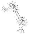
以下本発明をその実施の形態を示す図面に基づいて詳述する。図1は、車両の操舵装置における自在継手の使用状態の説明図である。図中1は、操舵部材としてのステアリングホイールの操作に応じて回転する操舵軸であり、また2は、舵取機構への回転入力のための入力軸(例えば、ラックピニオン式舵取機構のピニオン軸)である。
【0015】
操舵軸1は、車室の内部に位置決めされたステアリングホイールから下方に向けて延設され、また入力軸2は、車室の外部に固定支持された舵取機構から上方に向けて延設されており、軸心を交叉及び偏心させて対向する操舵軸1及び入力軸2の軸端部10,20の連結に、図示の如く、両端に自在継手3,3を備える中間軸4が用いられている。
【0016】
自在継手3,3は、二股に分岐したフォーク状のピン受けアーム32,33を一側に連設してなる各一対のヨーク30,31を備えており、これらのヨーク30,31を夫々のピン受けアーム32,33が略直角をなして交叉するように向き合わせ、両アーム32,33の先端を十字形のクロスピン34により連結して構成されている。
【0017】
このような自在継手3,3は、円筒形をなす一側のヨーク31,31を中間軸4の両端部に夫々外嵌固定し、該中間軸4と一体化されている。操舵軸1と入力軸2との中間軸4による連結は、両端の自在継手3,3の他側のヨーク30,30を、図1中に矢符により示す如く、操舵軸1の軸端部10及び入力軸2の軸端部20の夫々に径方向の外側から嵌め込み、各別に保持させることにより実現されており、このような連結を可能とするために、前記ヨーク30,30及び軸端部10,20は、以下に示す特徴的な構成を有している。
【0018】
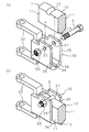
図2は、自在継手3のヨーク30と軸(図においては操舵軸1)との連結部分の斜視図である。図示の如くヨーク30は、略平行をなして対向する2枚の側板35,35の一側をアーチ形に湾曲する底板36により連絡し、他側が開放された略U字形の断面形状を有している。側板35,35には、底板36から離れて互いに対向する位置に、夫々を厚さ方向に貫通するボルト孔37,37が形成されており、また底板36の内面には、側板35,35間の略中央部に、これらの側板35,35と略平行をなして延びる矩形断面の凹溝38が形成されている。
【0019】
このようなヨーク30に連結される操舵軸1の軸端部10は、側板35,35間への嵌め込みが可能な2面幅を有して平坦化された当て面11,11を備える小判形断面に成形されている。当て面11,11の一側の連絡部には、軸長方向の中途部を略直交する向きに横切る半円形の押え溝12が形成されており、他側の連絡部には、軸長方向に延びる凸条13が、ヨーク30の底板36に形成された凹溝38への嵌め込みが可能な幅を有して形成されている。
【0020】
このような軸端部10とヨーク30との連結は、まずヨーク30と軸端部10とを、図2(a)に示す如く、ヨーク30の側板35,35間の開口部が軸端部10の凸条13の形成部に対面するように位置決めし、次いで、ヨーク30を軸端部10に、軸端部10の当て面11,11をヨーク30の側板35,35の内面に沿わせるように嵌め込んだ後、側板35,35に設けられたボルト孔37,37に、一方の側板35の外側から固定ボルト5を通し、他方の側板35の外側に突出する固定ボルト5のねじ部に締め付けナット50を螺合して締め付けることにより、側板35,35間に軸端部10の当て面11,11を挾圧せしめ、図2(b)に示す如く実現される。
【0021】
なおこのとき、軸端部10に設けられた押え溝12は、側板35,35間にてボルト孔37,37の形成位置に整合され、前述の如く挿通される固定ボルト5の中途部に係合せしめられており、該固定ボルト5とヨーク30の底板36との間に軸端部10を挾持し、該軸端部10を、側板35,35の開口側及び軸長方向への抜け出し不可に拘束する作用をなす。
【0022】
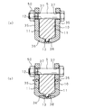
図3は、以上の如く実現される操舵軸1の軸端部10と自在継手3のヨーク30との連結構造の説明図であり、図3(a)は、固定ボルト5の締め付け前の状態を示し、図3(b)は、固定ボルト5の締め付け後の状態を示している。
【0023】
前述の如く、ヨーク30の側板35,35間への軸端部10の嵌め込みは、軸端部10に設けられた当て面11,11を側板35,35に沿わせてなされており、この嵌め込みの後の当て面11,11は、図3(a)に示す如く、嵌め込みのために必要なわずかなギャップを隔ててヨーク30の側板35,35の内面に対向しており、その後になされる固定ボルト5及び締め付けナット50の締め付けにより対向幅を減じる側板35,35により、図3(b)中に白抜矢符にて示す如く挾圧固定される。
【0024】
このとき、側板35,35による当て面11,11の挾圧強さは、固定ボルト5の締め付け位置に近い側板35,35の開口側においては強いが、締め付け位置から離れて位置する底板36の近傍においては弱いため、図3(b)に示す如く、側板35,35の内面と当て面11,11との間にギャップが残り、このギャップの幅内にて軸端部10がガタ付く虞れがある。
【0025】
ここで操舵軸1の軸端部10には、当て面11,11の一側の連絡部に凸条13が突設されており、この軸端部10が嵌め込まれるヨーク30の底板36には、側板35,35間の略中央に凹溝38が形成されている。ヨーク30の軸端部10への嵌め込みは、前述の如く、凸条13の突設側からなされており、この嵌め込みの後に凸条13は、ヨーク30の底板36に形成された凹溝38と図3(a)に示す如く係合する。この状態で固定ボルト5の締め付けがなされた場合、締め付けに伴う底板36の撓みにより凹溝38は、開口幅を減じるように変形し、図3(b)中に矢符により示す如く、内部に係合する凸条13の両側に押し付けられることとなり、底板36の近傍において生じる軸端部10のガタ付きは、凸条13を両側から挾持する凹溝38によって確実に阻止され、操舵軸1の軸端部10と自在継手3のヨーク30とは、ガタ付きの虞れなく連結される。
【0026】
この連結は、固定ボルト5及び締め付けナット50の単純な締め付けにより簡易に実現することができ、また、締め付け荷重を高精度に管理することなくガタ付きのない良好な連結がなされる。
【0027】
なお凹溝38は、底板26の内面の適宜位置に設けることが可能であるが、固定ボルト5に締め付けによる減幅を効果的に生ぜしめ、軸端部10の凸条13の挾持を確実に行わせるためには、以上の実施の形態に示す如く、2枚の側板35,35の略中央に軸長方向に延設するのが望ましい。また、以上の実施の形態においては、各1つの凸条13及び凹溝38を設けてあるが、各複数の凸条13及び凹溝38を設け、これらを各別に係合させる構成としてもよい。
【0028】
図1に示す操舵装置において、舵取機構への入力軸2の軸端部20と同側の自在継手3のヨーク30との連結も全く同様に実現されており、このような連結がなされた操舵装置においては、操舵軸1から中間軸4を介してなされる入力軸2への回転伝達が、ガタ音の発生、及びガタ付きに伴う応答遅れを生じることなく行われ、良好な操舵感が得られるようになる。
【0029】
なお、以上の実施の形態においては、車両の操舵装置への適用例について述べたが、本発明に係る自在継手と軸との連結構造は、略U字形断面を有するヨークを備える自在継手を用い、予め位置が定められた軸の軸端部同士を連結する用途全般に適用可能であり、同様の効果が得られることは言うまでもない。
【0030】
【発明の効果】
以上詳述した如く本発明に係る自在継手と軸との連結構造においては、自在継手のヨークの側板間に嵌め込まれた軸の2面幅部がヨークの底板近傍でガタ付くことを防止することができ、このガタ付きに伴う、ガタ音、応答遅れ等の不具合の発生を有効に防止して、自在継手により連結された軸間での伝動を良好に行わせることが可能となる等、本発明は優れた効果を奏する。
【図面の簡単な説明】
【図1】車両の操舵装置における自在継手の使用状態の説明図である。
【図2】自在継手のヨークと軸との連結部分の斜視図である。
【図3】自在継手のヨークと軸との連結構造の説明図である。
【図4】自在継手のヨークと軸との従来の連結構造の説明図である。
【符号の説明】
1 操舵軸(軸)
2 入力軸(軸)
3 自在継手
5 固定ボルト
10 軸端部
13 凸条
20 軸端部
30 ヨーク
35 側板
36 底板
38 凹溝[0001]
BACKGROUND OF THE INVENTION
The present invention relates to a connecting structure of a universal joint and a shaft used to connect two shafts whose shaft centers intersect or are eccentric so as to transmit rotation.
[0002]
[Prior art]
A universal joint is a pair of yokes with a fork-shaped pin receiving arm bifurcated on one side, facing each other so that each pin receiving arm crosses at a substantially right angle, and these are cross-shaped. It is a well-known machine element connected by a cross pin, and by connecting and fixing two target shafts to each yoke separately, in order to connect the two shafts whose shaft centers cross or eccentric so as to transmit rotation, It is used in many industrial fields.
[0003]
Such a universal joint is used, for example, in a steering apparatus of a vehicle to connect a steering shaft that rotates in response to an operation of a steering wheel as a steering member and an input shaft of a steering mechanism. The input shaft and the input shaft are separately attached to the inside and outside of the passenger compartment, and it is required to retrofit the respective yokes to the steering shaft and the shaft end portion of the input shaft fixed in the axial length direction. The Therefore, a universal joint is used in which at least one yoke has a substantially U-shaped cross section in which one side of two opposing side plates is connected by a bottom plate (see, for example, Patent Document 1). ).
[0004]
FIG. 4 is an explanatory diagram of this type of yoke-shaft connection structure. As shown in the figure, the
[0005]
Such a connection is realized by fitting the
[0006]
[Patent Document 1]
Japanese Patent Laid-Open No. 10-9281
[Problems to be solved by the invention]
However, in the connection structure of the
[0008]
In order to solve such a rattling problem, in Patent Document 1, the facing distance between the
[0009]
The present invention has been made in view of such circumstances, and the shaft end portion of the shaft fitted between the side plates of the yoke of the universal joint is not rattled even in the vicinity of the bottom plate located away from the tightening portion of the side plate. It is an object of the present invention to provide a connecting structure between a universal joint and a shaft that can be fixed and can effectively prevent the occurrence of problems due to the looseness.
[0010]
[Means for Solving the Problems]
The connecting structure between the universal joint and the shaft according to the first aspect of the present invention is to be connected to a universal joint including a yoke having a substantially U-shaped cross section in which one side of two opposing side plates is connected by a bottom plate. In order to connect the shaft, the shaft end portion is fitted between the side plates of the yoke through the opening on the other side, and the shaft end portion is tightened with a fixing bolt penetrating the side plate at a position away from the bottom plate. In the connecting structure of the universal joint and the shaft for fixing the two-surface width portion provided between the side plates , a concave groove having a rectangular cross section is formed on the inner surface of the bottom plate of the yoke on the outer surface of the shaft end portion of the shaft. Protrusions that can be engaged with the concave grooves are provided, the width of the concave grooves is reduced by tightening the fixing bolts, and the convex stripes are held.
[0011]
In the present invention, a concave groove having a rectangular cross section is provided on the inner surface of the bottom plate that connects the two side plates of the yoke having a substantially U-shaped cross section, and is provided on the outer surface of the shaft end portion of the shaft that is fitted between the two side plates. and keep the engaged ridges, by tightening the fixing bolt performed after this, 挾 to pressure fix the abutting surface provided with a 2 surface width in the axial end portion of the shaft between the inner surface of the side plate of the yoke At this time, the width of the groove is reduced to hold the ridge, thereby preventing rattling of the shaft end near the bottom plate of the yoke located away from the tightening position.
[0012]
In addition, the connecting structure between the universal joint and the shaft according to the second invention of the present invention is characterized in that the groove in the first invention extends in the axial length direction at the approximate center between the side plates.
[0013]
In the present invention, the concave groove provided in the bottom plate of the yoke is positioned approximately at the center of the two side plates and extends in the axial direction, effectively reducing the concave groove by tightening the fixing bolt, The protrusion that engages with the concave groove is securely held to increase the effect of preventing backlash.
[0014]
DETAILED DESCRIPTION OF THE INVENTION
Hereinafter, the present invention will be described in detail with reference to the drawings illustrating embodiments thereof. FIG. 1 is an explanatory diagram of a usage state of a universal joint in a vehicle steering apparatus. In the figure, 1 is a steering shaft that rotates in response to an operation of a steering wheel as a steering member, and 2 is an input shaft (for example, a pinion of a rack and pinion type steering mechanism) for rotational input to the steering mechanism. Axis).
[0015]
The steering shaft 1 extends downward from a steering wheel positioned inside the passenger compartment, and the input shaft 2 extends upward from a steering mechanism fixedly supported outside the passenger compartment. As shown in the drawing, an intermediate shaft 4 having
[0016]
Each of the
[0017]
The
[0018]
FIG. 2 is a perspective view of a connecting portion between the
[0019]
The
[0020]
Such connection between the
[0021]
At this time, the holding
[0022]
FIG. 3 is an explanatory view of a connection structure between the
[0023]
As described above, the fitting of the
[0024]
At this time, the
[0025]
Here, the
[0026]
This connection can be easily realized by simple tightening of the fixing
[0027]
Incidentally groove 38, it is possible to kick set at an appropriate position of the inner surface of the bottom plate 26, effectively caused the reduced width due to tightening the fixing
[0028]
In the steering apparatus shown in FIG. 1, the connection between the
[0029]
In the above embodiments, application examples to a vehicle steering apparatus have been described. However, the universal joint and shaft connection structure according to the present invention uses a universal joint including a yoke having a substantially U-shaped cross section. Needless to say, the present invention can be applied to all uses for connecting shaft end portions of shafts whose positions are determined in advance, and the same effect can be obtained.
[0030]
【The invention's effect】
Or in the coupling structure between the universal joint and the shaft according to detail the as the present invention, prevents Kukoto with gas data with the base plate near the second surface width portions of the yoke of shaft fitted between the side plates of the universal joint yoke it can be, due to with this play, Gataon, it is possible to effectively prevent the occurrence of non-degree, such as response delay, thereby satisfactorily perform the transmission between the shaft which is connected by a universal joint The present invention has excellent effects.
[Brief description of the drawings]
FIG. 1 is an explanatory diagram of a use state of a universal joint in a vehicle steering apparatus.
FIG. 2 is a perspective view of a connecting portion between a yoke and a shaft of a universal joint.
FIG. 3 is an explanatory diagram of a connection structure between a yoke and a shaft of a universal joint.
FIG. 4 is an explanatory view of a conventional connection structure between a yoke and a shaft of a universal joint.
[Explanation of symbols]
1 Steering shaft
2 Input shaft (axis)
3
10 Shaft end
13 ridges
20 Shaft end
30 York
35 Side plate
36 Bottom plate
38 groove
Claims (2)
前記ヨークの底板の内面に矩形断面を有する凹溝を、前記軸の軸端部の外面に前記凹溝に係合可能な凸条を夫々設け、前記固定ボルトの締め付けにより前記凹溝の幅を減じ、前記凸条を挾持させてあることを特徴とする自在継手と軸との連結構造。In order to connect a universal joint provided with a yoke having a substantially U-shaped cross section in which one side of two side plates facing each other is connected by a bottom plate and a shaft to be connected, a shaft end of the shaft is connected to the side plate of the yoke. A universal joint that is fitted through an opening on the other side in between and tightens a fixing bolt that penetrates the side plate at a position away from the bottom plate to fix the two-surface width portion provided at the shaft end portion between the side plates by pressure. In the connection structure of the shaft and
A concave groove having a rectangular cross section is provided on the inner surface of the bottom plate of the yoke, and a protrusion that can be engaged with the concave groove is provided on the outer surface of the shaft end of the shaft, and the width of the concave groove is increased by tightening the fixing bolt. A connecting structure of a universal joint and a shaft, characterized in that the protrusion is reduced and held up.
Priority Applications (1)
| Application Number | Priority Date | Filing Date | Title |
|---|---|---|---|
| JP2003160874A JP4178317B2 (en) | 2003-06-05 | 2003-06-05 | Connection structure of universal joint and shaft |
Applications Claiming Priority (1)
| Application Number | Priority Date | Filing Date | Title |
|---|---|---|---|
| JP2003160874A JP4178317B2 (en) | 2003-06-05 | 2003-06-05 | Connection structure of universal joint and shaft |
Publications (2)
| Publication Number | Publication Date |
|---|---|
| JP2004360814A JP2004360814A (en) | 2004-12-24 |
| JP4178317B2 true JP4178317B2 (en) | 2008-11-12 |
Family
ID=34053530
Family Applications (1)
| Application Number | Title | Priority Date | Filing Date |
|---|---|---|---|
| JP2003160874A Expired - Fee Related JP4178317B2 (en) | 2003-06-05 | 2003-06-05 | Connection structure of universal joint and shaft |
Country Status (1)
| Country | Link |
|---|---|
| JP (1) | JP4178317B2 (en) |
Families Citing this family (2)
| Publication number | Priority date | Publication date | Assignee | Title |
|---|---|---|---|---|
| JP5273129B2 (en) * | 2010-11-15 | 2013-08-28 | 日本精工株式会社 | Joint and shaft connection structure |
| CN113202878A (en) * | 2021-05-06 | 2021-08-03 | 杭州正强传动股份有限公司 | Universal joint fork |
-
2003
- 2003-06-05 JP JP2003160874A patent/JP4178317B2/en not_active Expired - Fee Related
Also Published As
| Publication number | Publication date |
|---|---|
| JP2004360814A (en) | 2004-12-24 |
Similar Documents
| Publication | Publication Date | Title |
|---|---|---|
| US7513709B2 (en) | Universal joint | |
| JPWO2003095286A1 (en) | Steering device | |
| CN103842676A (en) | Device for connecting a steering column to a steering gear housing | |
| JP2004278698A (en) | Connection structure between shaft body and shaft joint | |
| JP5217861B2 (en) | Connecting structure and steering device | |
| JP4178317B2 (en) | Connection structure of universal joint and shaft | |
| JP5156629B2 (en) | Universal joint yoke | |
| JP3658855B2 (en) | Joint between shaft and universal joint yoke | |
| JP2004232701A (en) | Combining structure between shaft body and shaft coupling | |
| JP4531692B2 (en) | Universal joint yoke | |
| WO2006022279A1 (en) | Structure for fixing lever switch | |
| JP2004360856A (en) | Interconnecting structure of universal joint and shaft | |
| JP4687981B2 (en) | Joint structure of universal joint yoke and shaft | |
| JP2007255533A (en) | Connecting structure of universal joint yoke and shaft, and power steering device | |
| JP4134938B2 (en) | Joint between shaft and universal joint yoke | |
| JP2005133790A (en) | Structure for connecting shaft to yoke of universal joint | |
| JP2006022869A (en) | Universal joint | |
| JP2010084897A (en) | Joint, and joining method of joint and shaft | |
| JP2007292188A (en) | Joint structure of universal joint yoke and shaft | |
| JP3556748B2 (en) | Connection structure between yoke and shaft of universal joint | |
| JP2014169732A (en) | Yoke coupling structure of shaft and yoke of universal joint, and vehicle steering device | |
| EP1632419B1 (en) | Joint section between shaft and universal joint yoke | |
| JP2011220416A (en) | Device for coupling yoke of joint with rotary shaft, and assembling method therefor | |
| JP2007263313A (en) | Joint structure of universal joint yoke and shaft | |
| JP2009079677A (en) | Joint structure of yoke and rotating shaft in steering device |
Legal Events
| Date | Code | Title | Description |
|---|---|---|---|
| A621 | Written request for application examination |
Free format text: JAPANESE INTERMEDIATE CODE: A621 Effective date: 20060524 |
|
| A977 | Report on retrieval |
Free format text: JAPANESE INTERMEDIATE CODE: A971007 Effective date: 20080121 |
|
| A131 | Notification of reasons for refusal |
Free format text: JAPANESE INTERMEDIATE CODE: A131 Effective date: 20080122 |
|
| A521 | Written amendment |
Free format text: JAPANESE INTERMEDIATE CODE: A523 Effective date: 20080324 |
|
| TRDD | Decision of grant or rejection written | ||
| A01 | Written decision to grant a patent or to grant a registration (utility model) |
Free format text: JAPANESE INTERMEDIATE CODE: A01 Effective date: 20080729 |
|
| A01 | Written decision to grant a patent or to grant a registration (utility model) |
Free format text: JAPANESE INTERMEDIATE CODE: A01 |
|
| A61 | First payment of annual fees (during grant procedure) |
Free format text: JAPANESE INTERMEDIATE CODE: A61 Effective date: 20080811 |
|
| R150 | Certificate of patent or registration of utility model |
Free format text: JAPANESE INTERMEDIATE CODE: R150 |
|
| FPAY | Renewal fee payment (event date is renewal date of database) |
Free format text: PAYMENT UNTIL: 20110905 Year of fee payment: 3 |
|
| FPAY | Renewal fee payment (event date is renewal date of database) |
Free format text: PAYMENT UNTIL: 20110905 Year of fee payment: 3 |
|
| FPAY | Renewal fee payment (event date is renewal date of database) |
Free format text: PAYMENT UNTIL: 20120905 Year of fee payment: 4 |
|
| FPAY | Renewal fee payment (event date is renewal date of database) |
Free format text: PAYMENT UNTIL: 20130905 Year of fee payment: 5 |
|
| LAPS | Cancellation because of no payment of annual fees |