JP2012193798A - Coupling structure for shaft and yoke of universal joint, and vehicle steering apparatus - Google Patents
Coupling structure for shaft and yoke of universal joint, and vehicle steering apparatus Download PDFInfo
- Publication number
- JP2012193798A JP2012193798A JP2011058335A JP2011058335A JP2012193798A JP 2012193798 A JP2012193798 A JP 2012193798A JP 2011058335 A JP2011058335 A JP 2011058335A JP 2011058335 A JP2011058335 A JP 2011058335A JP 2012193798 A JP2012193798 A JP 2012193798A
- Authority
- JP
- Japan
- Prior art keywords
- shaft
- serration
- universal joint
- formation region
- yoke
- Prior art date
- Legal status (The legal status is an assumption and is not a legal conclusion. Google has not performed a legal analysis and makes no representation as to the accuracy of the status listed.)
- Withdrawn
Links
Images


Abstract
Description
本発明は、シャフトと自在継手ヨークの結合構造およびこれを用いた車両用操舵装置に関する。 The present invention relates to a coupling structure of a shaft and a universal joint yoke and a vehicle steering apparatus using the same.
一般に、車両用操舵装置では、ステアリングホイールからの回転力を、ステアリングシャフト、インターミディエイトシャフト(中間軸)等を介して、例えばラックアンドピニオン機構等の転舵機構へと伝達し、これにより転舵輪を操向するようにしている。
インターミディエイトシャフトの上端は自在継手を介してステアリングシャフトと連結され、インターミディエイトシャフトの下端は自在継手を介してピニオンシャフトと連結されている。ステアリングシャフト、インターミディエイトシャフト、ピニオンシャフト等のシャフトを、対応する自在継手のヨークに結合する構造としては、自在継手のヨークのスリット付き筒状部を貫通する締め付けボルトを締め付けることにより、筒状部にセレーション嵌合されたシャフトを締め付けて固定する構造が提案されている(特許文献1参照)。
In general, in a vehicle steering apparatus, a rotational force from a steering wheel is transmitted to a steering mechanism such as a rack and pinion mechanism via a steering shaft, an intermediate shaft (intermediate shaft), etc. To steer.
The upper end of the intermediate shaft is connected to the steering shaft via a universal joint, and the lower end of the intermediate shaft is connected to the pinion shaft via a universal joint. As a structure for connecting a shaft such as a steering shaft, an intermediate shaft, and a pinion shaft to the yoke of the corresponding universal joint, the cylindrical portion A structure has been proposed in which a shaft that is serrated and fitted is fastened and fixed (see Patent Document 1).
また、筒状部にスリットを形成するときに生ずるバリを収容するスペースを形成するために、筒状部の内周において、スリットを挟んだ両側に片側40°程度の範囲で、セレーション歯を形成しない欠歯領域を設けることが提案されている(特許文献2を参照)。 In addition, in order to form a space for accommodating burrs generated when a slit is formed in the cylindrical portion, serration teeth are formed in a range of about 40 ° on one side on both sides of the slit on the inner periphery of the cylindrical portion. It has been proposed to provide a missing tooth region (see Patent Document 2).
ところで、締め付けボルトを締め付ける前段階において、シャフトの端部と自在継手のヨークの筒状部との嵌合は、組み付け性を考慮して、すきまばめとされている。
図6に示すように、シャフト70に嵌合しているヨーク71の筒状部72を、締め付けボルト73によって締め付けたときに、筒状部72の変位としては、スリット74に近い領域75が主に変形し、残りの部分は殆ど変形しない。また、筒状部72に変位としては、スリット74に近い領域75において、締め付け方向76(スリット74の狭まる方向。締め付けボルト73の軸方向)の変位が支配的である。
By the way, in the stage before tightening the tightening bolt, the fitting between the end portion of the shaft and the cylindrical portion of the yoke of the universal joint is a clearance fit in consideration of assembly.
As shown in FIG. 6, when the
したがって、セレーションの歯の接触としては、図6のD部拡大図である図7に示すように、スリット74に近い領域75においてのみ、締め付け方向76に概ね対向する歯面77,78でのみ接触していた。すなわち、少ない接触面積でセレーションの歯面が接触していた。
特許文献2に関しても、筒状部の内周を、スリットを中央部とする第1の半周部と、第1の半周部に対向する第2の半周部とした場合、第1の半周部においては、図8に示すように、欠歯領域79を除く部分でセレーションの歯面77,78同士の接触が確保されるものの、第2の半周部においては、セレーションの歯面同士が接触していないか、或いは仮に接触していも、トルク伝達が可能な接触状態まで至っていない(図示せず)。
Therefore, as the contact of the serration teeth, as shown in FIG. 7 which is an enlarged view of the D portion of FIG. 6, only in the
Also regarding
このため、接触面積が小さく、応力が高くなるため、長期の使用によって、セレーションの歯元が折損する場合があった。また、歯の接触面が摩耗(フレッティング摩耗)することにより、締め付けボルトの軸力が低下し、締結に緩みが生ずる場合がある。その場合、がたつき音による異音が発生したり、また、がたによって、操舵フィーリングが悪化したり、最悪の場合、摩耗が促進されて空転したりするおそれがある。 For this reason, since the contact area is small and the stress becomes high, the tooth root of the serration may be broken by long-term use. Further, when the contact surface of the teeth is worn (fretting wear), the axial force of the tightening bolt may be reduced, and the fastening may be loosened. In that case, there is a possibility that an abnormal noise due to rattling noise is generated, the steering feeling is deteriorated due to rattling, and in the worst case, wear is promoted to cause idling.
そこで、本発明の目的は、長期にわたって、がたつきの発生に伴う不具合を防止することができるシャフトと自在継手のヨークの結合構造を提供することである。また、本発明の目的は、長期にわたって、高品質であり低騒音と良好な操舵フィーリングを維持することができる車両用操舵装置を提供することである。 SUMMARY OF THE INVENTION Accordingly, an object of the present invention is to provide a coupling structure of a shaft and a universal joint yoke that can prevent problems associated with the occurrence of rattling over a long period of time. Another object of the present invention is to provide a vehicle steering apparatus that can maintain high quality, low noise and good steering feeling over a long period of time.
上記目的を達成するため、本発明は、端部(3a)を有するシャフト(3)と、上記シャフトの上記端部にセレーション嵌合された筒状部(15)を含む、自在継手のヨーク(12)と、上記筒状部をシャフトに締め付ける締め付け軸(21)と、を備え、上記筒状部は、軸方向に延びるスリット(16)を有し、上記シャフトの外周面(3b)および筒状部の内周面(15a)の何れか一方は、上記筒状部の周方向に関して上記スリットを中央部とするセレーション非形成領域(23;26;23A,23B)を有しており、上記筒状部の中心軸線(C1)を中心とする、上記セレーション非形成領域に対応する中心角(θ)は、100°〜140°の範囲内の所定値である、シャフトと自在継手のヨークの結合構造(P)を提供する(請求項1)。 To achieve the above object, the present invention provides a universal joint yoke (3) including a shaft (3) having an end (3a) and a cylindrical portion (15) serrated to the end of the shaft. 12) and a tightening shaft (21) for fastening the cylindrical part to the shaft, the cylindrical part has a slit (16) extending in the axial direction, and the outer peripheral surface (3b) of the shaft and the cylinder Any one of the inner peripheral surfaces (15a) of the shape portion has a serration non-formation region (23; 26; 23A, 23B) having the slit as a central portion in the circumferential direction of the cylindrical portion, A central angle (θ) corresponding to the serration non-formation region centered on the central axis (C1) of the cylindrical portion is a predetermined value within a range of 100 ° to 140 °, and the yoke of the shaft and the universal joint Provide a binding structure (P) (claims) 1).
本発明によれば、上記シャフトの外周面および筒状部の内周面の何れか一方に、スリットを中央部とするセレーション非形成領域が、中心角100°〜140°の範囲で設けられているので、締め付け軸によって筒状部を締め付けたときに、締め付け方向に略平行な方向に対向するセレーション嵌合領域において、歯面同士の接触を密にした強固なセレーション嵌合を実現することができる。 According to the present invention, a serration non-formation region having a slit as a central portion is provided in any one of the outer peripheral surface of the shaft and the inner peripheral surface of the cylindrical portion within a range of a central angle of 100 ° to 140 °. Therefore, when the cylindrical portion is tightened by the tightening shaft, it is possible to realize strong serration fitting with close contact between the tooth surfaces in the serration fitting region facing in a direction substantially parallel to the tightening direction. it can.
特に、上記中心角が100°未満の場合、スリットに近い領域のみで締め付けられるため、締め付け方向に略平行な方向に対向するセレーション嵌合領域におけるセレーション嵌合力が弱くなる。また、上記中心角が140°を超えると、締め付け方向に略平行な方向に対向するセレーション嵌合領域でのセレーション歯の噛み合わせ数が少なくなる。そこで、上記中心角を100°〜140°の範囲とすることにより、必要十分な歯数で且つ強固な嵌合力で嵌合されたセレーション嵌合部を得ることができる。 In particular, when the central angle is less than 100 °, tightening is performed only in the region close to the slit, so that the serration fitting force in the serration fitting region facing in a direction substantially parallel to the tightening direction is weakened. If the central angle exceeds 140 °, the number of engagement of serration teeth in the serration fitting region facing in a direction substantially parallel to the tightening direction is reduced. Therefore, by setting the central angle in the range of 100 ° to 140 °, it is possible to obtain a serration fitting portion fitted with a necessary and sufficient number of teeth and a strong fitting force.
また、上記セレーション非形成領域は、上記シャフトの上記外周面に形成されており、上記セレーション非形成領域に対応する中心角は、110°〜130°の範囲内の所定値である場合がある(請求項2)。この場合、シャフトの外周面のセレーション非形成領域に対応する中心角を110°以上とすることで、締め付け方向に略平行な方向に対向するセレーション嵌合領域におけるセレーション嵌合力を強くすることができ、しかも、上記中心角を130°以下とすることで、締め付け方向に略平行な方向に対向するセレーション嵌合領域でのセレーション歯の噛み合わせ数を多くすることができる。すなわち、必要十分な歯数で且つ強固な嵌合力で嵌合されたセレーション嵌合部を得ることができる。 The serration non-formation region is formed on the outer peripheral surface of the shaft, and the central angle corresponding to the serration non-formation region may be a predetermined value within a range of 110 ° to 130 ° ( Claim 2). In this case, by setting the central angle corresponding to the serration non-formation region on the outer peripheral surface of the shaft to be 110 ° or more, the serration fitting force in the serration fitting region facing the direction substantially parallel to the tightening direction can be increased. Moreover, by setting the central angle to 130 ° or less, it is possible to increase the number of meshing serration teeth in the serration fitting region facing the direction substantially parallel to the tightening direction. That is, it is possible to obtain a serration fitting portion fitted with a necessary and sufficient number of teeth and a strong fitting force.
また、上記セレーション非形成領域を第1のセレーション非形成領域(23A)として、上記シャフトの上記外周面および上記筒状部の上記内周面の何れか一方に、上記第1のセレーション非形成領域とは対向する第2のセレーション非形成領域(23B)が形成されている場合がある(請求項3)。この場合、例えば雌セレーション歯のブローチ加工において、切削抵抗を均一化することができるので、切削時のヨークの傾きを低減させて加工精度を向上させることができる。 Further, the first serration non-formation region (23A) is used as the first serration non-formation region (23A), and the first serration non-formation region is provided on one of the outer peripheral surface of the shaft and the inner peripheral surface of the cylindrical portion. In some cases, a second serration non-formation region (23B) that is opposite to is formed (claim 3). In this case, for example, in the broaching of female serration teeth, the cutting resistance can be made uniform, so that the inclination of the yoke at the time of cutting can be reduced and the machining accuracy can be improved.
また、上記セレーション非形成領域に隣接するセレーション歯(230;260)が、完全歯形をなしている場合がある(請求項4)。この場合、セレーション非形成領域に隣接するセレーション歯が、その一部を欠落した不完全な歯になることがないので、強度的に有利である。
また、本発明は、操舵部材(2)の操舵力を伝達するシャフト(3)を自在継手のヨークに結合する構造として、上記シャフトと自在継手のヨークの結合構造(P)が用いられている車両用操舵装置(1)を提供する(請求項5)。本発明によれば、長期にわたって摩耗によるガタが発生し難く、したがって、長期にわたって、高品質であり、低騒音と良好な操舵フィーリングを維持することができる。
The serration teeth (230; 260) adjacent to the non-serration region may form a complete tooth profile (claim 4). In this case, since the serrated tooth adjacent to the non-serrated region does not become an incomplete tooth lacking a part thereof, it is advantageous in terms of strength.
Further, in the present invention, as the structure for coupling the shaft (3) for transmitting the steering force of the steering member (2) to the yoke of the universal joint, the coupling structure (P) of the shaft and the universal joint yoke is used. A vehicle steering device (1) is provided (claim 5). According to the present invention, play due to wear hardly occurs over a long period of time, and therefore, high quality, low noise, and good steering feeling can be maintained over a long period of time.
なお、上記において、括弧内の英数字は、後述する実施形態における対応構成要素の参照符号を表すものであるが、これらの参照符号により特許請求の範囲を限定する趣旨ではない。 In the above description, the alphanumeric characters in parentheses represent reference numerals of corresponding components in the embodiments described later, but the scope of the claims is not limited by these reference numerals.
本発明の好ましい実施の形態を添付図面を参照しつつ説明する。
図1は本発明の一実施の形態に係るシャフトと自在継手のヨークとの結合構造Pが適用された車両用操舵装置1の概略構成を示す模式図である。図1を参照して、車両用操舵装置1は、ステアリングホイール等の操舵部材2に連結しているステアリングシャフト3と、ステアリングシャフト3に第1の自在継手4を介して連結されたインターミディエイトシャフト5と、インターミディエイトシャフト5に第2の自在継手6を介して連結されたピニオンシャフト7と、ピニオンシャフト7の端部近傍に設けられたピニオン7aに噛み合うラック8aを有して自動車の左右方向に延びる転舵軸としてのラック軸8とを有している。ピニオンシャフト7およびラックシャフト8によりラックアンドピニオン機構からなる転舵機構Aが構成されている。
Preferred embodiments of the present invention will be described with reference to the accompanying drawings.
FIG. 1 is a schematic diagram showing a schematic configuration of a vehicle steering apparatus 1 to which a coupling structure P between a shaft and a universal joint yoke according to an embodiment of the present invention is applied. Referring to FIG. 1, a vehicle steering apparatus 1 includes a
ラックシャフト8は、車体に固定されるハウジング9内に、滑り軸受であるラックブッシュ50を介して、軸方向W1に沿って直線往復動可能に支持されている。ラック軸8の両端部はハウジング9の両側へ突出し、各端部にはそれぞれタイロッド10が結合されている。各タイロッド10は対応するナックルアーム(図示せず)を介して対応する転舵輪11に連結されている。
The
操舵部材2が操作されてステアリングシャフト3が回転されると、この回転がピニオン7aおよびラック8aによって、自動車の左右方向に沿ってのラックシャフト8の直線運動に変換される。これにより、転舵輪11の転舵が達成される。
ステアリングシャフト3と第1の自在継手4に関して、本実施の形態のシャフトと自在継手のヨークとの結合構造Pが適用されている。具体的には、図2に示すように、第1の自在継手4は、ステアリングシャフト3の端部3aが連結される第1のヨーク12と、インターミディエイトシャフト5の端部5aが連結された第2のヨーク13と、第1のヨーク12および第2のヨーク13を連結する十字軸14とを備えている。ステアリングシャフト3の端部3aの外周にはセレーションが形成されている。
When the
With respect to the
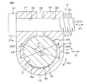
図2および図3を参照して、第1のヨーク12は、ステアリングシャフト3の端部3aが嵌合される筒状部15を有している。図3に示すように、筒状部15には、軸方向に延びるスリット16が設けられている。第1のヨーク12は、スリット16を挟んだ両側に一対のタブ17,18を有している。
各タブ17,18に設けられたボルト挿通孔19,20に、締め付け軸としての締め付けボルト21が挿通されている。締め付けボルト21の先端部21bに係合されたナット22と締め付けボルト21の頭部21aとの間で、一対のタブ17,18が締め付けられ、これにより、ステアリングシャフト3の端部3aが筒状部15内で締め付けられている。
Referring to FIGS. 2 and 3, the
A tightening
筒状部15の内周面15aには、雌セレーションが設けられている一方、筒状部15の周方向R1に関してスリット16を中央部とする雌セレーション非形成領域23(欠歯領域)が設けられている。筒状部15の中心軸線C1を中心とする、雌セレーション非形成領域23に対応する中心角θは、100°〜140°の範囲内の所定値、例えば100°や、例えば120°や、例えば140°に設定されている。
A female serration is provided on the inner
本実施の形態によれば、第1の自在継手4の第1のヨーク12の筒状部15の内周面15aに、スリット16を中央部とする雌セレーション非形成領域23を設け、その雌セレーション非形成領域23に対応する中心角θを、100°〜140°の範囲内の所定値に設定したので、締め付けボルト21によって筒状部15を締め付けたときに、締め付け方向X1(締め付けボルト21の軸方向に相当)とは平行な方向Y1(ないし締め付け方向X1とは略平行な方向)に対向するセレーション嵌合領域24,25において、歯面同士の接触を密にした強固なセレーション嵌合を実現することができる。
According to the present embodiment, the female
すなわち、中心角θが100°未満の場合、スリット16に近い領域のみで締め付けられるため、締め付け方向X1とは平行な方向Y1(ないし締め付け方向X1とは略平行な方向)に対向するセレーション嵌合領域24,25におけるセレーション嵌合力が弱くなる。また、中心角θが140°を超えると、締め付け方向X1とは平行な方向Y1(ないし締め付け方向X1とは略平行な方向)に対向するセレーション嵌合領域24,25でのセレーション歯の噛み合わせ数が少なくなる。そこで、中心角θを100°〜140°の範囲とすることにより、必要十分な歯数で且つ強固な嵌合力で嵌合されたセレーション嵌合領域24,25を得ることができる。
That is, when the central angle θ is less than 100 °, the fastening is performed only in the region close to the
また、上記結合構造Pをステアリングシャフト3と第1の自在継手4の第1のヨーク12との結合に適用した車両用操舵装置1によれば、長期にわたって摩耗によるガタが発生し難く、したがって、長期にわたって、低騒音と良好な操舵フィーリングを維持することができる。
また、図4において、雌セレーション非形成領域23に隣接する雌セレーション歯230が、完全歯形をなしていることが好ましい。雌セレーション非形成領域23に隣接する雌セレーション歯230が、その一部を欠落した不完全な歯になることがないので、強度的に有利であるからである。
Further, according to the vehicle steering apparatus 1 in which the coupling structure P is applied to the coupling between the steering
Moreover, in FIG. 4, it is preferable that the
次いで、図4は本発明の第2の実施の形態を示している。図4を参照して、本実施の形態が、図3の実施の形態と主に異なるのは、図3の実施の形態のように第1のヨーク12の筒状部15の内周面15aに設けられた雌セレーション非形成領域23に代えて、ステアリングシャフト3の外周面3bに、雄セレーション非形成領域26を設けた点にある。 本実施の形態において、雄セレーション非形成領域26に対応する中心角θは、100°〜130°の範囲内の所定値に設定されることが好ましい。また、雄セレーション非形成領域26に隣接する雄セレーション歯260が、完全歯形をなしていることが好ましい。
Next, FIG. 4 shows a second embodiment of the present invention. Referring to FIG. 4, this embodiment is mainly different from the embodiment of FIG. 3 in that the inner
本実施の形態の構成要素において、図3の実施の形態と同じ構成要素には、同一の符号を付してある。
本実施の形態においても、締め付けボルト21によって筒状部15を締め付けたときに、締め付け方向X1(締め付けボルト21の軸方向に相当)とは平行な方向Y1(ないし締め付け方向X1とは略平行な方向)に対向するセレーション嵌合領域24,25において、歯面同士の接触を密にした強固なセレーション嵌合を実現することができる。
In the constituent elements of the present embodiment, the same constituent elements as those in the embodiment of FIG. 3 are denoted by the same reference numerals.
Also in the present embodiment, when the
特に、ステアリングシャフト3の外周面3bの雄セレーション非形成領域26に対応する中心角θを110°以上とすることで、締め付け方向X1に平行な方向Y1(ないし締め付け方向X1に略平行な方向)に対向するセレーション嵌合領域24,25におけるセレーション嵌合力を強くすることができる。しかも、上記中心角θを130°以下とすることで、締め付け方向X1に平行な方向Y1(ないし締め付け方向X1に略平行な方向)に対向するセレーション嵌合領域24,25でのセレーション歯の噛み合わせ数を多くすることができる。すなわち、必要十分な歯数で且つ強固な嵌合力で嵌合されたセレーション嵌合を得ることができる。
In particular, by setting the central angle θ corresponding to the male
また、雄セレーション非形成領域26に隣接する雄セレーション歯260が、完全歯形をなしている場合には、雄セレーション非形成領域26に隣接する雄セレーション歯260が、その一部を欠落した不完全な歯になることがなく、強度的に有利である。
また、上記結合構造Pをステアリングシャフト3と第1の自在継手4の第1のヨーク12との結合に適用した車両用操舵装置1によれば、長期にわたって摩耗によるガタが発生し難く、したがって、長期にわたって、低騒音と良好な操舵フィーリングを維持することができる。
In addition, when the
Further, according to the vehicle steering apparatus 1 in which the coupling structure P is applied to the coupling between the steering
なお、本実施の形態において、ステアリングシャフト3の外周面3bに、上記雄セレーション非形成領域26を第1の雄セレーション非形成領域として、その第1の雄セレーション非形成領域に対して、締め付け方向X1とは直交する方向に対向する第2の雄セレーション非形成領域(図示せす)を設けるようにしてもよい。
次いで、図5は本発明の第3の実施の形態を示している。図5を参照して、本実施の形態が、図3の実施の形態と異なるのは、第1の自在継手4の第1のヨーク12の筒状部15の内周面15aにおいて、図3の実施の形態の雌セレーション非形成領域23に相当する第1の雌セレーション非形成領域23Aと、その第1の雌セレーション非形成領域23Aに対向する第2の雌セレーション非形成領域23Bを設けた点にある。
In the present embodiment, the male
Next, FIG. 5 shows a third embodiment of the present invention. Referring to FIG. 5, the present embodiment differs from the embodiment of FIG. 3 on the inner
第1の雌セレーション非形成領域23Aと第2の雌セレーション非形成領域23Bとは、締め付け方向X1とは直交する方向Z1である。本実施の形態の構成要素において、図3の実施の形態と同じ構成要素には、同一の符号を付してある。
第2の雌セレーション非形成領域23Bに対応する中心角θ2は、第1の雌セレーション非形成領域23Aに対応する中心角θと同じく、100°〜140°の範囲内の所定値に設定される。第1の雌セレーション非形成領域23Aに対向する第2の雌セレーション非形成領域23Bを設けることにより、下記の利点がある。すなわち、雌セレーション歯のブローチ加工において、切削抵抗を均一化することができるので、切削時のヨークの傾きを低減させて加工精度を向上させることができる。この観点から、中心角θ2の値は、中心角θの値と等しくすることが、好ましい。
The first female
The central angle θ2 corresponding to the second female
本実施の形態においても、締め付けボルト21によって筒状部15を締め付けたときに、締め付け方向X1(締め付けボルト21の軸方向に相当)とは平行な方向Y1(ないし締め付け方向X1とは略平行な方向)に対向するセレーション嵌合領域24,25において、歯面同士の接触を密にした強固なセレーション嵌合を実現することができる。また、上記結合構造Pをステアリングシャフト3と第1の自在継手4の第1のヨーク12との結合に適用した車両用操舵装置1によれば、長期にわたって摩耗によるガタが発生し難く、したがって、長期にわたって、低騒音と良好な操舵フィーリングを維持することができる。
Also in the present embodiment, when the
上記各実施の形態では、ステアリングシャフト3と第1の自在継手4の第1のヨーク12との結合構造に、本発明の結合構造Pを適用したが、本発明は、操舵力を伝達するシャフトとしてのステアリングシャフト3、インターミディエイトシャフト5およびピニオンシャフト7の何れかを、対応する自在継手4,6の対応するヨークに結合する構造に適用することができる。その他、本発明の請求項記載の範囲内で種々の変更を施すことができる。
In each of the above embodiments, the coupling structure P of the present invention is applied to the coupling structure of the
1…車両用操舵装置、2…操舵部材、3…ステアリングシャフト、4…第1の自在継手、5…インターミディエイトシャフト、6…第2の自在継手、7…ピニオンシャフト、8…ラックシャフト、A…転舵機構、P…(シャフトと自在継手のヨークの)結合構造、12…第1のヨーク、13…第2のヨーク、14…十字軸、15…筒状部、15a…(筒状部の)内周面、16…スリット、17,18…タブ、19,20…ボルト挿通孔、21…締め付けボルト(締め付け軸)、23…雌セレーション非形成領域、230…雌セレーション歯(セレーション非形成領域に隣接するセレーション歯)、23A…第1の雌セレーション非形成領域、23B…第2の雌セレーション非形成領域、24,25…(締め付け方向とは平行な方向に対向する)セレーション嵌合領域、26…雄セレーション非形成領域、260…雄セレーション歯(セレーション非形成領域に隣接するセレーション歯)、X1…締め付け方向、Y1…締め付け方向とは平行な方向、Z1…締め付け方向とは直交する方向、θ,θ2…中心角 DESCRIPTION OF SYMBOLS 1 ... Vehicle steering device, 2 ... Steering member, 3 ... Steering shaft, 4 ... 1st universal joint, 5 ... Intermediate shaft, 6 ... 2nd universal joint, 7 ... Pinion shaft, 8 ... Rack shaft, A ... Steering mechanism, P ... Coupling structure (of shaft and universal joint yoke), 12 ... First yoke, 13 ... Second yoke, 14 ... Cross shaft, 15 ... Cylindrical part, 15a ... (Cylindrical part) ) Inner peripheral surface, 16 ... slit, 17, 18 ... tab, 19, 20 ... bolt insertion hole, 21 ... clamping bolt (tightening shaft), 23 ... female serration non-formation region, 230 ... female serration tooth (serration non-formation) Serration teeth adjacent to the region), 23A ... first female serration non-formation region, 23B ... second female serration non-formation region, 24, 25 ... (facing in a direction parallel to the tightening direction) Serration fitting area, 26 ... male serration non-formation area, 260 ... male serration tooth (serration teeth adjacent to the serration non-formation area), X1 ... tightening direction, Y1 ... direction parallel to tightening direction, Z1 ... tightening direction Are orthogonal directions, θ, θ2, ... center angle
Claims (5)
上記シャフトの上記端部にセレーション嵌合された筒状部を含む、自在継手のヨークと、
上記筒状部をシャフトに締め付ける締め付け軸と、を備え、
上記筒状部は、軸方向に延びるスリットを有し、
上記シャフトの外周面および筒状部の内周面の何れか一方は、上記筒状部の周方向に関して上記スリットを中央部とするセレーション非形成領域を有しており、上記筒状部の中心軸線を中心とする、上記セレーション非形成領域に対応する中心角は、100°〜140°の範囲内の所定値である、シャフトと自在継手のヨークの結合構造。 A shaft having an end;
A universal joint yoke including a cylindrical portion serrated to the end of the shaft;
A fastening shaft for fastening the tubular part to the shaft,
The cylindrical part has a slit extending in the axial direction,
Either one of the outer peripheral surface of the shaft and the inner peripheral surface of the cylindrical portion has a serration non-formation region having the slit as a central portion in the circumferential direction of the cylindrical portion, and the center of the cylindrical portion A joint structure of a shaft and a universal joint yoke, wherein a central angle corresponding to the serration non-formation region centered on an axis is a predetermined value within a range of 100 ° to 140 °.
上記セレーション非形成領域に対応する中心角は、110°〜130°の範囲内の所定値である、シャフトと自在継手のヨークの結合構造。 In claim 1, the serration non-formation region is formed on the outer peripheral surface of the shaft,
A coupling structure of a shaft and a universal joint yoke, wherein a central angle corresponding to the serration non-formation region is a predetermined value within a range of 110 ° to 130 °.
Priority Applications (1)
| Application Number | Priority Date | Filing Date | Title |
|---|---|---|---|
| JP2011058335A JP2012193798A (en) | 2011-03-16 | 2011-03-16 | Coupling structure for shaft and yoke of universal joint, and vehicle steering apparatus |
Applications Claiming Priority (1)
| Application Number | Priority Date | Filing Date | Title |
|---|---|---|---|
| JP2011058335A JP2012193798A (en) | 2011-03-16 | 2011-03-16 | Coupling structure for shaft and yoke of universal joint, and vehicle steering apparatus |
Publications (1)
| Publication Number | Publication Date |
|---|---|
| JP2012193798A true JP2012193798A (en) | 2012-10-11 |
Family
ID=47085882
Family Applications (1)
| Application Number | Title | Priority Date | Filing Date |
|---|---|---|---|
| JP2011058335A Withdrawn JP2012193798A (en) | 2011-03-16 | 2011-03-16 | Coupling structure for shaft and yoke of universal joint, and vehicle steering apparatus |
Country Status (1)
| Country | Link |
|---|---|
| JP (1) | JP2012193798A (en) |
Cited By (2)
| Publication number | Priority date | Publication date | Assignee | Title |
|---|---|---|---|---|
| JP2015178858A (en) * | 2014-03-19 | 2015-10-08 | 日本精工株式会社 | Universal joint and steering device having the universal joint |
| JP2020076435A (en) * | 2018-11-06 | 2020-05-21 | 日本精工株式会社 | Yoke for universal joint and connecting structure of yoke for universal joint and rotating shaft |
-
2011
- 2011-03-16 JP JP2011058335A patent/JP2012193798A/en not_active Withdrawn
Cited By (3)
| Publication number | Priority date | Publication date | Assignee | Title |
|---|---|---|---|---|
| JP2015178858A (en) * | 2014-03-19 | 2015-10-08 | 日本精工株式会社 | Universal joint and steering device having the universal joint |
| JP2020076435A (en) * | 2018-11-06 | 2020-05-21 | 日本精工株式会社 | Yoke for universal joint and connecting structure of yoke for universal joint and rotating shaft |
| JP7067430B2 (en) | 2018-11-06 | 2022-05-16 | 日本精工株式会社 | Universal joint yoke and joint structure between universal joint yoke and rotating shaft |
Similar Documents
| Publication | Publication Date | Title |
|---|---|---|
| JP5088387B2 (en) | Cross shaft type universal joint | |
| JP5092913B2 (en) | Universal joint yoke and universal joint | |
| US8500564B2 (en) | Shaft-and-yoke coupling structure and vehicle steering system | |
| US20150040715A1 (en) | Steering system for a motor vehicle | |
| JP6016005B2 (en) | Universal joint and yoke | |
| WO2012086678A1 (en) | Electric power steering device | |
| JP2012193798A (en) | Coupling structure for shaft and yoke of universal joint, and vehicle steering apparatus | |
| JP6673308B2 (en) | Torque transmission shaft for steering | |
| WO2020105582A1 (en) | Torque transmission shaft | |
| JP2009299776A (en) | Worm reduction gear and electric power steering device | |
| JP2014077493A (en) | Fastening structure of shaft and yoke | |
| JP6344467B2 (en) | Cross shaft type universal joint yoke | |
| JP6673309B2 (en) | Torque transmission shaft | |
| JP2014169732A (en) | Yoke coupling structure of shaft and yoke of universal joint, and vehicle steering device | |
| JP5093284B2 (en) | Cross shaft type universal joint | |
| JP7099157B2 (en) | A method for manufacturing a joint portion between a shaft and a clamp member and a joint portion between a shaft and a clamp member. | |
| JP2014101969A (en) | Yoke joint structure of universal joint | |
| JP7119580B2 (en) | Shaft connection structure | |
| JP2012180909A (en) | Structure for connecting universal joint york and shaft | |
| JP5163683B2 (en) | Coupling device for joint yoke and rotating shaft and method for assembling the same | |
| JP7119284B2 (en) | UNIVERSAL JOINT AND STEERING DEVICE WITH THE UNIVERSAL JOINT | |
| JP2009191973A (en) | Yoke for universal coupling, and universal coupling | |
| JP2014238132A (en) | Coupling device and vehicle steering device employing coupling device | |
| JP2016185782A (en) | Steering device | |
| JP2013047543A (en) | Joint york and joint |
Legal Events
| Date | Code | Title | Description |
|---|---|---|---|
| A300 | Withdrawal of application because of no request for examination |
Free format text: JAPANESE INTERMEDIATE CODE: A300 Effective date: 20140603 |