JP2004225301A - Eaves edge structure of corner section or trough section and eaves edge construction method - Google Patents
Eaves edge structure of corner section or trough section and eaves edge construction method Download PDFInfo
- Publication number
- JP2004225301A JP2004225301A JP2003012613A JP2003012613A JP2004225301A JP 2004225301 A JP2004225301 A JP 2004225301A JP 2003012613 A JP2003012613 A JP 2003012613A JP 2003012613 A JP2003012613 A JP 2003012613A JP 2004225301 A JP2004225301 A JP 2004225301A
- Authority
- JP
- Japan
- Prior art keywords
- eaves
- corner
- valley
- main material
- girder
- Prior art date
- Legal status (The legal status is an assumption and is not a legal conclusion. Google has not performed a legal analysis and makes no representation as to the accuracy of the status listed.)
- Pending
Links
Images


Abstract
Description
【0001】
【発明の属する技術分野】
本発明は、木造またはこれに準じた木質系構造からなる屋根架構の、隅部や谷部における軒先構造と軒先工法に関する。
【0002】
【従来の技術】
木質系の工業化住宅における屋根架構では、勾配屋根の隅部や谷部を、図7に示すような構造とするのが一般的である。図示の例は寄棟屋根等に形成される隅部であるが、2本の軒桁1(1a,1b)、またはこれに類する横架材等が直交状態で接合された出隅角部A上に、軒先まで延出する隅木2を斜めに載せ架けて固定する。隅木2の図示しない上端部は、棟木、棟束または小屋束(当該屋根が下層階の下屋根の場合は柱)等に接合する。そして、隅木2の両側面から前記各軒桁1にかけて、屋根の勾配方向に沿う複数本の垂木3を適宜間隔で取り付ける。垂木3も軒先まで延出させ、隅木2及び垂木3の先端を軒先母屋4等で水平方向に連結する。さらに、これらの垂木3に野地板や屋根パネル等を取り付ける。
【0003】
このような屋根構造では、隅木2の断面形状が、単純な矩形ではなく、縦方向の中心面を境にして天端及び下端が両側に下り傾斜した山形状になるのが通常である。そのため、このような隅木2を軒桁1の出隅角部Aに固定するに際しては、両材の接合面を特殊な形状に切欠加工して係合させたり、専用の接合金物を介して接合している。かかる接合構造は、例えば特許文献1〜5等に提案されている。
【0004】
【特許文献1】
特開平7−34585号公報
【特許文献2】
特開平7−34586号公報
【特許文献3】
特開平7−34587号公報
【特許文献4】
特開平11−1986号公報
【特許文献5】
特開平11−247345号公報
【0005】
【発明が解決しようとする課題】
前記のような屋根構造では、軒先部分を精度良く仕上げるために、軒先の出寸法を厳密に調整する必要がある。この出寸法は、軒桁の位置が基準となる。軒先の出寸法調整に際しては、軒桁1の天端に現場で通り墨Xを打ち、隅木2の側面には軒先を基準にして割り出した腹墨Yを打って、隅木2の腹墨Yを軒桁1の通り墨Xに合わせる。隅木2が正確に位置決めされたならば、続いて垂木3も同様に位置決めする。
【0006】
このような位置決め作業においては、当然ながら、隅木2自体を、軒桁1の出隅角部A上に載架した状態で、材長方向に微小寸法ずつ移動させる作業が発生する。しかし、寸法の長大な隅木2を、足場の不自由な高所で、しかも斜め方向に位置決めするのは、相当の手間と困難を伴う作業である。
【0007】
とりわけ近年では、工業化住宅の分野において部材のユニット化やパネル化が進み、接合部にも合理的な金物が多用されるようになって、小屋組架構のスパンや構造部材の断面寸法が大きくなる傾向にある。そのため、隅木等も長大化、大断面化しており、前記のような位置決め作業にも、さらなる工数を要している。
【0008】
しかも、隅木2の固定が完了するまでは、垂木3や軒先母屋4等を取り付ける次工程に進むことができない。隅木2の位置決めに手間取ると、他の作業員の無駄な手待ち時間が発生することとなり、施工効率が低下してしまう。かかる実情は、屋根の隅部だけでなく、谷部についても全く同様である。
【0009】
そこで本発明は、隅部や谷部において軒先の出寸法調整を容易に行いうる新規な軒先構造を提供し、屋根施工の効率化を図ることを解決課題とする。
【0010】
【課題を解決するための手段】
本発明の隅部の軒先構造は、軒桁またはこれに類する横架材と、建物本体側の棟木、棟束、小屋束、柱またはこれらに類する構造材との間に隅木が斜めに架設され、この隅木の下端部が前記軒桁または前記横架材に連結されるとともに、この隅木の下端部には、軒先部分の屋根荷重を支持する軒隅木が、前記隅木の延長方向に連結されたことを特徴とする。
【0011】
さらに、前記軒隅木は、隅木と同幅の断面寸法を有する主材と、この主材の両側面にそれぞれ添着された添材とからなり、各添材は主材よりも建物本体側に延出されて、この延出部分が隅木の各側面に重合した状態で隅木に対しビスまたは釘で固定されるとともに、主材の天端と隅木の天端とが平帯状の補強金物を介して連結されたことを特徴とする。
【0012】
また、本発明の谷部の軒先構造は、軒桁またはこれに類する横架材と、建物本体側の棟木、棟束、小屋束、柱またはこれらに類する構造材との間に谷木が斜めに架設され、この谷木の下端部が前記軒桁または前記横架材に連結されるとともに、この谷木の下端部には、軒先部分の屋根荷重を支持する軒谷木が、前記谷木の延長方向に連結されたことを特徴とする。
【0013】
さらに、前記軒谷木は、谷木と同幅の断面寸法を有する主材と、この主材の両側面にそれぞれ添着された添材とからなり、各添材は主材よりも建物本体側に延出されて、この延出部分が谷木の各側面に重合した状態で谷木に対しビスまたは釘で固定されるとともに、主材の天端と谷木の天端とが平帯状の補強金物を介して連結されたことを特徴とする。
【0014】
また、本発明の隅部・谷部の軒先工法は、軒先に面した軒桁またはこれに類する横架材と、建物本体側に設けられる棟木、棟束、小屋束、柱またはこれらに類する構造材との間に隅木または谷木を斜めに架設して、前記隅木または谷木の下端部を前記軒桁または前記横架材に連結した後、前記隅木または谷木の下端部に、軒先部分の屋根荷重を支持する軒隅木または軒谷木を、前記隅木または谷木の延長方向に連結することを特徴とする。
【0015】
【発明の実施の形態】
以下、本発明の実施の形態について、それぞれ図面を参照しつつ説明する。なお、前記従来の屋根構造(図7)に示した軒先部分の構成と共通する部位・部材には、共通の名称及び符号を使用する。
【0016】
<屋根架構>
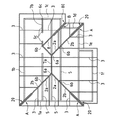
図1は、本発明の実施の形態にかかる変形勾配屋根の伏図であり、図2は、図1に示す屋根の小屋組架構を模式的に表した斜視図である。
【0017】
図1及び図2において、符号1(1a,1b,1c,…)は軒桁またはこれに相当する梁などの横架材である。符号5は小屋梁で、符号6a,6b,6cは前記小屋梁上に立設される小屋束及び棟束である。ただし、本説明においては、棟部を支持する棟束6a,6cと、それ以外の小屋束6bとを特に区別しない場合、これらを束材6と総称する。棟束6a同士、及び棟束6c同士は、それぞれ棟木7(7a,7b)を介して連結される。
【0018】
この屋根は、3箇所の隅部と、1箇所の谷部を有する。隅部には隅木2(2a,2b)が、谷部には谷木8が、それぞれ斜めに架設される。そして、棟木7、隅木2または谷木8から、各軒桁1にかけて、垂木3が架設される。以下、隅部・谷部の構造について、それぞれ詳述する。
【0019】
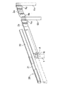
<隅部>
図3〜図4は、隅部の詳細な構造を示す。例示の形態では、隅木2は、上部の隅木2aと下部の隅木2bに分割され、上部の隅木2aは棟束6aと小屋束6bとの間に、下部の隅木2bは小屋束6bと出隅角部Aとの間に、それぞれ架設されている。また、この形態では、隅木2と連結される棟束6a及び小屋束6bが、建物の通り心方向に対し軸回りに45度、回動されて、束材6の側面が隅木2の材心と直交するように立設されている。
【0020】
隅木2と束材6や軒桁1とは、図示のような鋼板製の接合金物9(9a,9b,9c)を介して連結される。束材6側の接合金物9a,9bは、背板の両側縁部から二片の連結板を突設させたもので、背板を束材6にボルト・ナット締結し、連結板を隅木2の端部に形成したスリットに挿入して、隅木2の側面からドリフトピンを打込むことにより、隅木2と束材6とを連結する。また、軒桁1側の接合金物9cは、ほぞパイプの一端に一片の連結板を突設させたもので、ほぞパイプを軒桁1に形成したほぞ孔に挿入してドリフトピンで固定し、連結板を隅木2の端部に形成したスリットに挿入してドリフトピンで固定する。
【0021】
このように、本発明においては、隅木2の下端部が軒桁1までの長さに形成されて、軒先まで延出しない。したがって、前記のような接合金物9により、軒桁1や束材6との間に若干のクリアランスを設けて隅木2を連結すれば、隅木2を軒先の出寸法に合わせて位置決めする作業は不要になり、隅木2を容易かつ迅速に架設することができる。
【0022】
また、この構造では、隅木2を軒桁1と束材6のみで支持しており、隅木2には母屋梁等の横架材が接合されない。そのため、隅木2の断面形状は、図4中に添付した断面図に示すように、下端を平坦にすることができ、天端にのみ山形状の傾斜面を形成すればよい。これにより、隅木2の部材加工が容易になり、軒桁1との連結部も、前記従来の技術に記載したような複雑な接合形態に比べて格段に簡素化される。
【0023】
そして、軒桁1上に固定された隅木2の下端部に、本発明の要部をなす軒隅木20が継ぎ足され、この軒隅木20が軒先部分の屋根荷重を支持する。
【0024】
軒隅木20は、隅木2と同幅の断面寸法を有する主材21と、この主材21の両側面にそれぞれ添着された添材22とからなる。主材21と添材22とは、接着またはビス止めによって強固に接合されている。主材21及び添材22の断面形状は、図4中の断面図に示すように、天端と下端とが、それぞれ山形状の傾斜面をなすように形成されている。
【0025】
主材21の長さは、出隅角部Aから軒先ラインZまでの出寸法に基づいて予め加工されており、主材21と添材22の先端は軒先ラインZに合致するように揃えられている。添材22の他端は主材21よりも建物本体側に延出されており、この延出部分が隅木2の両側面に重ねられて、図示しないビスまたは釘で隅木2に固定される。この釘やビスは、添材22の延出部分の範囲内で乱に打つことができる。さらに、主材21の天端と隅木2の天端に平帯状の補強金物23を重ね、これを主材21及び隅木2にビス止めして、両者の接合部が補強される。
【0026】
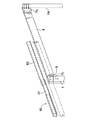
<谷部>
図5〜図6は、谷部の詳細な構造を示す。例示の形態にかかる谷木8は、1本の連続する部材で、棟束6aと入隅角部Bとの間に架設される。谷木8と棟束6aや軒桁1との接合部にも、前記隅部と同様の接合金物9が用いられる。谷部においても、谷木8の下端部が軒桁1までの長さに形成されるので、谷木8の架設に際して面倒な軒先の出寸法調整は必要ない。
【0027】
そして、軒桁1上に谷木8が固定された後、谷木8の下端部に軒谷木80が継ぎ足される。軒谷木80も、前記した軒隅木20と同様に、谷木2と同幅の断面寸法を有する主材81と、この主材81の両側面にそれぞれ添着された添材82とからなる。主材81及び添材82の断面形状は、図6中に添付した断面図に示すように、天端と下端とが、それぞれ逆山形状の傾斜面をなすように形成されている。
【0028】
主材81の長さは、入隅角部Bから軒先ラインZまでの出寸法に基づいて予め加工されており、主材81と添材82の先端は軒先ラインZに合致するように揃えられている。添材82の他端は主材81よりも建物本体側に延出され、この延出部分が谷木8の両側面に重ねられて、ビスまたは釘で固定される。さらに、主材81の天端と谷木8の天端に平帯状の補強金物23を重ね、これを主材81及び谷木8にビス止めして、両者の接合部が補強される。
【0029】
このように、本発明では、隅部・谷部における軒先の出寸法を、隅木2・谷木8に継ぎ足される軒隅木20・軒谷木80によって調整する。これらの軒隅木20・軒谷木80は、隅木2や谷木8に比べて短く軽量なので、位置決め及び固定作業を容易かつ迅速に行うことができる。また、隅木2や谷木8が軒桁1上に載架されれば直ちに、垂木3や小屋組補強材等を架設する工程に進むことができるので、現場での無駄な手待ち時間も解消されて、施工効率が向上する。
【0030】
【発明の効果】
本発明では、隅木や谷木を軒先に突出しない長さに形成して軒桁上に載架固定した後、その下端部に軒隅木や軒谷木を継ぎ足す構造を採用しているので、長大な隅木や谷木を位置決めする作業が不要になり、軒先の出寸法調整が容易になる。これにより、現場での施工効率が向上する。
【図面の簡単な説明】
【図1】本発明の実施の形態にかかる変形屋根の伏図である。
【図2】図1に示す変形屋根の小屋組架構を模式的に表した斜視図である。
【図3】図1の変形屋根における隅部の構造を示す側面図である。
【図4】同じく、隅部の構造を示す上面図である。
【図5】図1の変形屋根における谷部の構造を示す側面図である。
【図6】同じく、谷部の構造を示す上面図である。
【図7】従来の屋根架構における隅部の構造を示す斜視図である。
【符号の説明】
1 軒桁
2 隅木
20 軒隅木
21 主材
22 添材
23 補強金物
6 束材
7 棟木
8 谷木
80 軒谷木
81 主材
82 添材[0001]
TECHNICAL FIELD OF THE INVENTION
TECHNICAL FIELD The present invention relates to an eaves structure and an eaves construction method at a corner or a valley of a roof frame having a wooden structure or a wooden structure similar thereto.
[0002]
[Prior art]
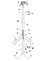
In a roof frame of a wood-based industrialized house, a corner or a valley of a sloped roof is generally structured as shown in FIG. The illustrated example is a corner formed on a roof of a ridge or the like, but a protruding corner A where two eaves girder 1 (1a, 1b) or a similar horizontal member is joined in an orthogonal state. A
[0003]
In such a roof structure, the cross section of the
[0004]
[Patent Document 1]
JP-A-7-34585 [Patent Document 2]
JP-A-7-34586 [Patent Document 3]
JP-A-7-34587 [Patent Document 4]
JP-A-11-1986 [Patent Document 5]
JP-A-11-247345
[Problems to be solved by the invention]
In the roof structure as described above, it is necessary to precisely adjust the protrusion dimension of the eaves in order to finish the eaves with high accuracy. This projection dimension is based on the position of the eaves girder. At the time of adjusting the extension of the eaves, a black ink X is struck at the top of the eaves girder 1 at the site, and a black ink Y on the side of the
[0006]
In such a positioning operation, naturally, the operation of moving the
[0007]
In particular, in recent years, in the field of industrialized housing, unitization and panelization of members have been advanced, and reasonable hardware has been frequently used for joints, so that the span of a cabin frame structure and the cross-sectional dimensions of structural members have increased. There is a tendency. For this reason, corners and the like are also becoming longer and larger in cross section, and the positioning work as described above requires more man-hours.
[0008]
In addition, it is not possible to proceed to the next step of attaching the
[0009]
Therefore, an object of the present invention is to provide a new eaves structure in which the eaves can be easily adjusted at corners and valleys to improve the efficiency of roof construction.
[0010]
[Means for Solving the Problems]
In the eaves structure at the corner of the present invention, a corner block is diagonally erected between an eave girder or a similar horizontal member and a purlin, ridge bundle, hut bundle, pillar or similar structural material on the building body side. The lower end of the corner block is connected to the eaves girder or the cross member, and the lower end of the corner block is connected to an eaves corner supporting the roof load of the eaves portion in the extending direction of the corner block. It is characterized by the following.
[0011]
Further, the eave corner block is composed of a main member having the same cross-sectional dimension as the corner block, and additional members attached to both side surfaces of the main member. Each of the additional members extends closer to the building body than the main member. It is taken out, and this extension part is fixed to each corner with screws or nails in a state of being superimposed on each side of the corner, and the top of the main material and the top of the corner are through a reinforcing strip in the form of a flat strip. It is characterized by being connected.
[0012]
Further, the valley eaves structure of the present invention is such that a valley is inclined between an eaves girder or a similar horizontal member and a ridge, ridge, shed, pillar or similar structural material on the building body side. The lower end of the valley is connected to the eave girder or the cross member, and the lower end of the valley is provided with an eave valley that supports the roof load of the eaves portion. It is characterized by being connected in a direction.
[0013]
Further, the eaves valley is composed of a main material having the same cross-sectional dimension as the valley, and additional materials attached to both sides of the main material. To the valley with screws or nails attached to the valley in a state where the extended portion overlaps each side of the valley, and the top of the main material and the top of the valley are flat strip-shaped. It is characterized by being connected via a reinforcing metal.
[0014]
Further, the corner / valley eaves construction method of the present invention comprises an eaves girder facing the eaves or a transverse member similar thereto, and a purlin, a bundle, a shed bundle, a pillar or a similar structure provided on the building body side. A corner or a valley is erected diagonally between the timber and the lower end of the corner or the valley is connected to the eaves girder or the cross member. An eaves corner or an eaves valley supporting a load is connected in the extension direction of the corners or the valleys.
[0015]
BEST MODE FOR CARRYING OUT THE INVENTION
Hereinafter, embodiments of the present invention will be described with reference to the drawings. Note that common names and reference numerals are used for parts and members common to the configuration of the eaves tip shown in the conventional roof structure (FIG. 7).
[0016]
<Roof frame>
FIG. 1 is a plan view of a deformed gradient roof according to an embodiment of the present invention, and FIG. 2 is a perspective view schematically showing a hut frame structure of the roof shown in FIG.
[0017]
1 and 2, reference numeral 1 (1a, 1b, 1c,...) Denotes a transverse member such as an eaves girder or a beam corresponding thereto.
[0018]
This roof has three corners and one valley. Corner trees 2 (2a, 2b) are installed at the corners, and
[0019]
<Corner>
3 and 4 show the detailed structure of the corner. In the illustrated embodiment, the
[0020]
The
[0021]
Thus, in the present invention, the lower end of the
[0022]
Further, in this structure, the
[0023]
An
[0024]
The
[0025]
The length of the
[0026]
<Tanibe>
5 and 6 show the detailed structure of the valley. The
[0027]
Then, after the
[0028]
The length of the
[0029]
As described above, in the present invention, the outgoing dimensions of the eaves at the corners and the valleys are adjusted by the
[0030]
【The invention's effect】
In the present invention, after the corners and valleys are formed to a length that does not protrude from the eaves and fixed on the eaves girder, a structure is employed in which the eaves corners and eaves valleys are added to the lower end thereof. This eliminates the need for positioning long corners and valleys, making it easier to adjust the eaves dimension. Thereby, the construction efficiency on site is improved.
[Brief description of the drawings]
FIG. 1 is a plan view of a deformed roof according to an embodiment of the present invention.
FIG. 2 is a perspective view schematically showing a cabin frame structure with a deformed roof shown in FIG.
FIG. 3 is a side view showing a structure of a corner in the modified roof of FIG. 1;
FIG. 4 is also a top view showing the structure of the corner.
FIG. 5 is a side view showing a structure of a valley in the modified roof in FIG. 1;
FIG. 6 is a top view showing the structure of the valley.
FIG. 7 is a perspective view showing a structure of a corner in a conventional roof frame.
[Explanation of symbols]
1
Claims (5)
この隅木の下端部には、軒先部分の屋根荷重を支持する軒隅木が、前記隅木の延長方向に連結されたことを特徴とする隅部の軒先構造。A corner block is installed diagonally between the eaves girder or similar horizontal member and the purlins, ridges, shed bundles, columns or similar structural materials on the building body side, and the lower end of this corner is the eaves girder. Or, while being connected to the horizontal member,
An eaves corner structure in which an eaves corner supporting a roof load of the eaves portion is connected to a lower end portion of the corners in an extending direction of the corner eaves.
主材の天端と隅木の天端とが平帯状の補強金物を介して連結されたことを特徴とする請求項1に記載の隅部の軒先構造。An eaves corner is composed of a main material having the same cross-sectional dimensions as the corner wood, and additional materials attached to both sides of the main material, and each additional material is extended toward the building body side from the main material. , While this extension part is fixed to the corner block with screws or nails in a state of overlapping on each side of the corner block,
2. The eaves structure at a corner according to claim 1, wherein the top of the main material and the top of the corner are connected via a flat band-shaped reinforcing metal.
この谷木の下端部には、軒先部分の屋根荷重を支持する軒谷木が、前記谷木の延長方向に連結されたことを特徴とする谷部の軒先構造。A valley is installed diagonally between the eaves girder or similar horizontal member and the ridge, ridge, shed, pillar or similar structural material on the building body side, and the lower end of the valley is attached to the eave. Connected to the girder or the horizontal member,
An eaves valley structure in which an eaves valley supporting a roof load of an eaves portion is connected to a lower end portion of the valley in an extending direction of the valley.
主材の天端と谷木の天端とが平帯状の補強金物を介して連結されたことを特徴とする請求項1に記載の谷部の軒先構造。An eaves valley consists of a main material having the same cross-sectional dimensions as the valley, and additional materials attached to both sides of the main material. Then, with this extension part fixed to the valley with screws or nails in a state of overlapping on each side of the valley,
The eaves structure of a valley part according to claim 1, wherein the top end of the main material and the top end of the valley are connected via a flat band-shaped reinforcing hardware.
前記隅木または谷木の下端部に、軒先部分の屋根荷重を支持する軒隅木または軒谷木を、前記隅木または谷木の延長方向に連結することを特徴とする隅部・谷部の軒先工法。A corner or valley is installed diagonally between an eaves girder facing the eaves or a similar horizontal material and a ridge, ridge, shed, pillar or similar structural material provided on the building body side. After connecting the lower end of the corner block or valley to the eave girder or the cross member,
A corner / valley eaves construction method, wherein an eaves corner or eaves valley for supporting a roof load of an eaves part is connected to a lower end of the corners or valley in an extending direction of the corners or valley.
Priority Applications (1)
| Application Number | Priority Date | Filing Date | Title |
|---|---|---|---|
| JP2003012613A JP2004225301A (en) | 2003-01-21 | 2003-01-21 | Eaves edge structure of corner section or trough section and eaves edge construction method |
Applications Claiming Priority (1)
| Application Number | Priority Date | Filing Date | Title |
|---|---|---|---|
| JP2003012613A JP2004225301A (en) | 2003-01-21 | 2003-01-21 | Eaves edge structure of corner section or trough section and eaves edge construction method |
Publications (1)
| Publication Number | Publication Date |
|---|---|
| JP2004225301A true JP2004225301A (en) | 2004-08-12 |
Family
ID=32901169
Family Applications (1)
| Application Number | Title | Priority Date | Filing Date |
|---|---|---|---|
| JP2003012613A Pending JP2004225301A (en) | 2003-01-21 | 2003-01-21 | Eaves edge structure of corner section or trough section and eaves edge construction method |
Country Status (1)
| Country | Link |
|---|---|
| JP (1) | JP2004225301A (en) |
Cited By (2)
| Publication number | Priority date | Publication date | Assignee | Title |
|---|---|---|---|---|
| JP2006207280A (en) * | 2005-01-28 | 2006-08-10 | Sekisui House Ltd | Eaves structure of inclined roof |
| WO2022168625A1 (en) * | 2021-02-03 | 2022-08-11 | 積水ハウス株式会社 | Shed roofing structure |
-
2003
- 2003-01-21 JP JP2003012613A patent/JP2004225301A/en active Pending
Cited By (5)
| Publication number | Priority date | Publication date | Assignee | Title |
|---|---|---|---|---|
| JP2006207280A (en) * | 2005-01-28 | 2006-08-10 | Sekisui House Ltd | Eaves structure of inclined roof |
| JP4507897B2 (en) * | 2005-01-28 | 2010-07-21 | 積水ハウス株式会社 | Eaves structure of sloped roof |
| WO2022168625A1 (en) * | 2021-02-03 | 2022-08-11 | 積水ハウス株式会社 | Shed roofing structure |
| GB2617000A (en) * | 2021-02-03 | 2023-09-27 | Sekisui House Kk | Shed roofing structure |
| JP7439777B2 (en) | 2021-02-03 | 2024-02-28 | 積水ハウス株式会社 | roof frame structure |
Similar Documents
| Publication | Publication Date | Title |
|---|---|---|
| JP2004225301A (en) | Eaves edge structure of corner section or trough section and eaves edge construction method | |
| JP7218665B2 (en) | Roof structure and roof structure construction method | |
| JP2020073763A (en) | Mounting fitting and roof | |
| JP3373470B2 (en) | How to install truss truss members | |
| JP4105032B2 (en) | Wooden roof panels | |
| JPH11336242A (en) | Roof truss structure of small roof and execution method thereof | |
| JP3877062B2 (en) | Extension construction method of hut assembly | |
| JPH1162021A (en) | Beam connection structure, steel beam provided with beam connection metal fitting, and beam connection method | |
| JP2535656B2 (en) | Building structure | |
| JP7198672B2 (en) | Bent beam and roof truss structure | |
| JP2719076B2 (en) | Building roof and construction method | |
| JP3377483B2 (en) | Roof base frame structure | |
| JP3241878B2 (en) | Corner block receiving structure | |
| JPS5814732Y2 (en) | Attachment device for purlins to corner beams | |
| JPH10169085A (en) | Frame structure of roof | |
| JPH0756417Y2 (en) | Beam climbing and purlin joint structure | |
| JP3907309B2 (en) | Eaves-end unit and eaves-end unit joining method | |
| JP2582104Y2 (en) | Roof structure | |
| JP2004225302A (en) | Roof truss structure | |
| JPH07259237A (en) | Roof panel fitting structure | |
| JPS647135Y2 (en) | ||
| JP2004044082A (en) | Extension working method of roof truss | |
| JP2018066156A (en) | Metal fitting and roof | |
| JPH10102662A (en) | Independent strutted roof frame | |
| JPH05340041A (en) | Connecting structure for roof panel |