JP2004211971A - Outdoor unit of air conditioner - Google Patents
Outdoor unit of air conditioner Download PDFInfo
- Publication number
- JP2004211971A JP2004211971A JP2002382588A JP2002382588A JP2004211971A JP 2004211971 A JP2004211971 A JP 2004211971A JP 2002382588 A JP2002382588 A JP 2002382588A JP 2002382588 A JP2002382588 A JP 2002382588A JP 2004211971 A JP2004211971 A JP 2004211971A
- Authority
- JP
- Japan
- Prior art keywords
- curved portion
- outdoor unit
- bell mouth
- flat portion
- curved
- Prior art date
- Legal status (The legal status is an assumption and is not a legal conclusion. Google has not performed a legal analysis and makes no representation as to the accuracy of the status listed.)
- Pending
Links
Images

Landscapes
- Other Air-Conditioning Systems (AREA)
- Air-Flow Control Members (AREA)
Abstract
【課題】空気流によって発生する騒音をより低減することができる空気調和機の室外機を提供する。
【解決手段】空気調和機の室外機は、回転軸を有する送風ファンとベルマウス9とを備える。ベルマウス9は、湾曲部92と平面部93とを有する。湾曲部92は、送風ファンによって回転軸方向に生じる空気流が通る開口を構成し、空気流の吸込み側へと近づくにつれて開口が広がるように曲率半径Rで湾曲する。平面部93は、湾曲部92の吸込み側の外縁の少なくとも一部から延設される。そして、回転軸を端部とする半平面で平面部93を切った断面における平面部93の長さを表す平面部長さLの最大値Lmと、湾曲部92の曲率半径Rとの比Lm/Rが、0.5≦Lm/R≦1.5である。
【選択図】 図6An outdoor unit of an air conditioner that can further reduce noise generated by an air flow.
An outdoor unit of an air conditioner includes a blower fan having a rotating shaft and a bell mouth. The bellmouth 9 has a curved portion 92 and a flat portion 93. The curved portion 92 forms an opening through which an airflow generated by the blower fan in the rotation axis direction passes, and is curved with a radius of curvature R such that the opening becomes wider as approaching the airflow suction side. The flat portion 93 extends from at least a part of the outer edge of the curved portion 92 on the suction side. Then, a ratio Lm / maximum value Lm of the flat portion length L representing the length of the flat portion 93 in a cross section obtained by cutting the flat portion 93 with a half plane having the rotation axis as an end and the radius of curvature R of the curved portion 92. R satisfies 0.5 ≦ Lm / R ≦ 1.5.
[Selection] Fig. 6
Description
【0001】
【発明の属する技術分野】
本発明は、空気調和機の室外機、特にベルマウスを備える空気調和機の室外機に関する。
【0002】
【従来の技術】
空気調和機の室外機には送風ファンが備えられ、送風ファンによって、室外機内に取り込まれ再び室外機の外部へと吹き出す空気流が生成される。そして、室外機から吹き出す空気の出口近傍には、図15に示すようなベルマウスが設けられ、室外へと吹き出す空気の流路が形成されることが多い。送風ファンによって生じた空気流はこのベルマウスを通過するが、このとき空気流による騒音が発生することがある。このため、従来、空気流の吸込み側に湾曲部が設けられたベルマウスが考案されている(特許文献1参照)。このベルマウスの湾曲部は、送風ファンによって生じる空気流が通る開口を構成しており、図16に示すように、空気流の吸込み側へと近づくにつれて開口が広がるように曲率半径Rで湾曲している。なお、図14において、右側が吸込み側であり、左側が吹出し側である。
【0003】
このような湾曲部がベルマウスの吸い込み側の外縁を構成することにより、空気流が円滑にベルマウスを通過することができ、空気流による騒音が低減される。
【0004】
【特許文献1】
特開平11−14101号公報(第1(b)図および第1(c)図)
【0005】
【発明が解決しようとする課題】
上記のような湾曲部がベルマウスの吸い込み側の外縁を構成することにより、空気流による騒音が低減する。しかし、空気調和機の使用者等にとっては、このような騒音はより低減されることが望ましい。
本発明の課題は、空気流によって発生する騒音をより低減することができる空気調和機の室外機を提供することにある。
【0006】
【課題を解決するための手段】
請求項1に記載の空気調和機の室外機は、回転軸を有する送風ファンと、ベルマウスとを備える。ベルマウスは、湾曲部と平面部とを有する。湾曲部は、送風ファンによって回転軸方向に生じる空気流が通る開口を構成し、空気流の吸込み側へと近づくにつれて開口が広がるように曲率半径Rで湾曲する。平面部は、湾曲部の吸込み側の外縁の少なくとも一部から延設される。そして、回転軸を端部とする半平面で平面部を切った断面における平面部の長さを表す平面部長さLの最大値Lmと、湾曲部の曲率半径Rとの比Lm/Rが、0.5≦Lm/R≦1.5である。
【0007】
この空気調和機の室外機では、湾曲部の吸込み側の外縁の少なくとも一部から平面部が延設されている。このため、ベルマウスへと吸い込まれる空気が湾曲部の吸込み側の外縁で巻き込まれることが平面部によって抑えられる。従って、湾曲部の吸込み側の外縁近傍での空気流の乱れを低減することができ、空気流による騒音を低減することができる。また、このような騒音の低減の効果は、平面部長さLと、湾曲部の曲率半径Rとに関係し、平面部長さLの最大値Lmと、湾曲部の曲率半径Rとの比Lm/Rが、0.5≦Lm/R≦1.5であることが望ましいことが、本願の発明者によって明らかになった。そして、この空気調和機の室外機は、この条件に適合するベルマウスを備えるため、空気流による騒音をより低減することができる。
【0008】
請求項2に記載の空気調和機の室外機は、請求項1に記載の空気調和機の室外機であって、平面部は、開口を挟んで対向するように設けられる。
この空気調和機の室外機では、平面部は、開口を挟んで対向するように設けられる。このため、この空気調和機の室外機では、送風音の偏りを低減することができる。
【0009】
請求項3に記載の空気調和機の室外機は、請求項1または2に記載の空気調和機の室外機であって、ベルマウスは、平面部と湾曲部とにわたって設けられるリブを有する。このリブは、平面部の吹出し側表面および湾曲部の湾曲の内側表面から起立しており、リブの稜線が平面部および湾曲部に近づくように凹んでいる。
【0010】
ベルマウスに平面部が設けられる場合、補強のために湾曲部と平面部とにわたってリブが設けられることが望ましい。しかし、このリブが空気流の妨げとなると、空気流による騒音が発生し易くなる。
この空気調和機の室外機では、リブは、平面部の吹出し側表面および湾曲部の湾曲の内側表面から起立しており、リブの稜線が平面部および湾曲部に近づくように凹んでいる。このため、リブが設けられている側の湾曲部と平面部との表面に沿って流れる空気流がリブによって妨げられることが低減している。これにより、この空気調和機の室外機では、リブによって騒音が生じる恐れを低減することができる。
【0011】
請求項4に記載の空気調和機の室外機は、第1回転軸を有する第1送風ファンと、第1ベルマウスと、第2回転軸を有する第2送風ファンと、第2ベルマウスとを備える。第1ベルマウスは、第1湾曲部と第1平面部とを有する。第1湾曲部は、第1送風ファンによって第1回転軸方向に生じる空気流が通る開口を構成し、空気流の吸込み側へと近づくにつれて開口が広がるように曲率半径R1で湾曲する。第1平面部は、第1湾曲部の吸込み側の外縁の少なくとも一部から延設される。第2送風ファンは、第1送風ファンと並んで設けられる。第2ベルマウスは、第1ベルマウスと並んで設けられ、第2湾曲部と第2平面部とを有する。第2湾曲部は、第2送風ファンによって第2回転軸方向に生じる空気流が通る開口を構成し、空気流の吸込み側へと近づくにつれて開口が広がるように曲率半径R2で湾曲する。第2平面部は、第2湾曲部の吸込み側の外縁の少なくとも一部から延設される。そして、第1回転軸を端部とする半平面で第1平面部を切った断面における第1平面部の長さを表す第1平面部長さL1の最大値Lm1と、第1湾曲部の曲率半径R1との比Lm1/R1が、0.5≦Lm1/R1≦1.5である。また、第2回転軸を端部とする半平面で第2平面部を切った断面における第2平面部の長さを表す第2平面部長さL2の最大値Lm2と、第2湾曲部の曲率半径R2との比Lm2/R2が、0.5≦Lm2/R2≦1.5である。そして、第1平面部と第2平面部とは、第1湾曲部と第2湾曲部とが近接する部分近傍を除いて設けられる。
【0012】
この空気調和機の室外機では、第1湾曲部の吸込み側の外縁の少なくとも一部から第1平面部が延設される。また、第2湾曲部の吸込み側の外縁の少なくとも一部から第2平面部が延設される。このため、第1ベルマウスや第2ベルマウスへと吸い込まれる空気が第1湾曲部や第2湾曲部の吸込み側の外縁近傍で巻き込まれることが抑えられる。従って、第1湾曲部や第2湾曲部の吸込み側の外縁での空気流の乱れを低減することができ、空気流による騒音を低減することができる。また、このような騒音の低減の効果は、第1平面部長さL1と、第1湾曲部の曲率半径R1とに関係し、第1平面部長さL1の最大値Lm1と、第1湾曲部の曲率半径R1との比Lm1/R1が、0.5≦Lm1/R1≦1.5であることが望ましく、同様に、第2平面部長さL2の最大値Lm2と、第2湾曲部の曲率半径R2との比Lm2/R2が、0.5≦Lm2/R2≦1.5であることが望ましいことが、本願の発明者によって明らかになった。そして、この空気調和機の室外機は、この条件の第1ベルマウスおよび第2ベルマウスを備えるため、空気流による騒音をより低減することができる。
【0013】
また、第1ベルマウスと第2ベルマウスとが並設される場合、空気調和機の室外機の大型化を抑制するという観点からは、第1ベルマウスと第2ベルマウスとは近接して配置されることが望ましい。
この空気調和機の室外機では、第1平面部と第2平面部とは、第1湾曲部と第2湾曲部とが近接する部分近傍を除いて設けられる。このため、第1平面部と第2平面部とが第1ベルマウスと第2ベルマウスとを近接させて設ける際の妨げとなる恐れが少ない。これにより、第1ベルマウスと第2ベルマウスとを近接させて設けることが容易になっており、空気調和機の室外機の大型化を抑制することができる。
【0014】
請求項5に記載の空気調和機の室外機は、請求項4に記載の空気調和機の室外機であって、第1ベルマウスの外縁および第2ベルマウスの外縁が略四角形に形成されている。
第1ベルマウスと第2ベルマウスとが並設される場合、第1ベルマウスと第2ベルマウスとが円形となっていると、第1ベルマウスと第2ベルマウスとの間に隙間が生じ易い。
【0015】
しかし、この空気調和機の室外機では、第1ベルマウスの外縁および第2ベルマウスの外縁が略四角形に形成されている。このため、第1ベルマウスと第2ベルマウスとが並設される場合でも、ベルマウスの平面部の間に隙間が生じ難くなっている。
【0016】
【発明の実施の形態】
<第1実施形態>
[全体構成]
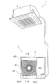
本発明の第1実施形態が採用された空気調和機1の外観を図1に示す。空気調和機1は、室内に配置される室内機2と、室外に配置される室外機3とに分かれたセパレート型の空気調和機である。なお、図中では1台の室内機2が室外機3に接続されているが、一台の室外機3に複数台の室内機2が接続されてもよい。
【0017】
[室外機の概略構成]
室外機3は、略箱状のケーシング4を有しており、ケーシング4の内部は、仕切り板によって、左右に、通気室SP1と機械室SP2との2つの空間にそれぞれ分けられている。
左側に位置する通気室SP1は、室外熱交換器が配置され室外熱交換器を通って熱交換される空気が通る空間である。ケーシング4の前面には前板40が設けられている。前板40は、板金から形成されており、吹出し口41が設けられている。また、吹出し口41の前面には格子状の保護パネル42が設けられている。室外機3の背面から通気室SP1に吸い込まれた空気は、吹出し口41から排出される。なお、通気室SP1の背面側は開かれており、通気室SP1の背面側から室外の空気が通気室SP1へと取り込まれる。
【0018】
右側に位置する機械室SP2は、通気室SP1からある程度隔離された空間となっており、圧縮機や四路切換弁、電装品などが収容されている。
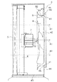
通気室SP1には、図2に示すように、室外熱交換器5、ファンモータ台6、ファンモータ7、送風ファン8、ベルマウス9などが配置されている。なお、図2は、室外機3の側面断面の模式図であるが、理解の容易のために、ファンモータ台6、ファンモータ7、送風ファン8については側面図として記載している。
【0019】
室外熱交換器5は、空気調和機1の冷媒回路の一部を構成しており、通過する空気との間で熱交換を行う。ファンモータ台6は、室外熱交換器5の前方に配置されており、下端が室外機3のケーシング4の底板43の上面に固定されている。ファンモータ7は、ファンモータ台6に支持されており、送風ファン8を回転駆動する。ファンモータ7は、中心軸が、水平方向に、すなわち、室外機3の正面および背面に垂直な方向を向くように配置されている。ファンモータ7の前方には、送風ファン8およびベルマウス9が配置されている。送風ファン8は、複数の羽を有するプロペラファンであり、ファンモータ台6およびファンモータ7の前方に位置している。送風ファン8は、ファンモータ7の回転軸72に固定されており、ファンモータ7によって回転駆動されることにより、空気の流れを生成する。ベルマウス9は、前板40の内側に取り付けられ、送風ファン8の周囲を覆うように配置されている。前板40およびベルマウス9については後に詳述する。送風ファン8によって生成された空気流は、外部から室外機3の背面側を通って室外機3内に取り込まれ、室外熱交換器5を通り、ベルマウス9の開口および前板40の吹出し口41を通って外部へと吹き出す(破線矢印A1参照)。
【0020】
[前板40の構成]
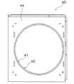
図3に前板40の正面図を示す。
前板40は、略板状の部材であり、室外機3の前面側に配置されている。前板40は、前板平面部44と吹出し部45とにより構成されている。
前板平面部44は、板状の部材であり、室外機3の前面を覆っている。前板平面部44の中央付近には、円形の開口からなる吹出し口41が設けられている。
【0021】
吹出し部45は、図2に示すように、吹出し口41の縁から連続して室外機3の内側へと突出する環状の部分であり、送風ファン8によって生じる空気流が通る円形の開口を構成している。吹出し部45と吹出し口41とが連続する部分には微小なアール面が形成されている。また、吹出し部45は、送風ファン8の前側部分の周囲を覆うように配置されている。
【0022】
[ベルマウス9の構成]
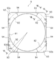
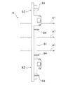
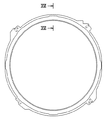
図4にベルマウス9の正面図、図5にベルマウス9の左側面図を示す。なお、図4は、ベルマウス9を前面側から見た図である。
ベルマウス9は、前板40の吹出し部45と共に、室外へと吹き出す空気が通る空気経路を形成している。ベルマウス9は、前板40の内側に配置されており、その外縁が略四角形状になっている。ベルマウス9は、円筒部91と、湾曲部92と平面部93とを有している。
【0023】
円筒部91は、薄肉の円筒形状を有している。円筒部91は、ベルマウス9の前側部分に、すなわち吹出し側部分を構成しており、送風ファン8によって生じる空気流が通る円形の開口を構成している。円筒部91は、中心が送風ファン8の回転軸と一致するように配置されており、内径が前板40の吹出し部45の内径と一致するように形成されている。このため、ベルマウス9が前板40に取り付けられた状態では、円筒部91の内周面と吹出し部45の内周面とが合致した状態となる。
【0024】
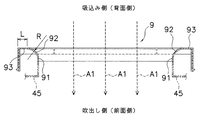
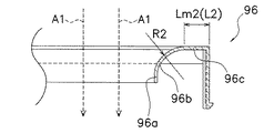
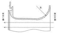
湾曲部92は、送風ファン8によって回転軸方向に生じる空気流が通る円形の開口を構成しており、回転軸方向の空気流の吸込み側へと近づくにつれて開口が広がるように曲率半径Rで湾曲している。湾曲部92は、円筒部91と共に空気経路を形成しており、開口の中心が送風ファン8の回転軸と一致するように配置されている。図6にベルマウス9の断面図を示す。湾曲部92は、環状の形状を有しており、空気流の吸込み側へと近づくにつれて、開口の径方向外側へと曲率半径Rで湾曲している。なお、図6では、図中上側が空気流の吸込み側(上流側)すなわち室外機3の背面側であり、図中下側が空気流の吹出し側(下流側)すなわち室外機3の前面側となっている。湾曲部92は、前側では円筒部91と同一の内径となっており、背面側へと近づくにつれて内径が拡大している。湾曲部92の吸込み側の外周縁は、図4に示すように、正面視において孔の周囲に沿った4つの円弧状の部分(図中の二点鎖線参照)と、各円弧の端部を繋ぐ直線状の部分とによって形成されている。湾曲部92の外周縁の直線状の部分は、四角形状のベルマウス9の外縁に沿った形状となっている。4つの円弧状の部分は、それぞれ対になって開口を挟んで対向するように配置されている。
【0025】
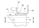
平面部93は、図4に示すように、湾曲部92の外周縁の4つの円弧状の部分からそれぞれ延設されており、開口を挟んで対向するように設けられている。具体的には、平面部は、4つの部分93a,93b,93c,93dに分かれて設けられており、各部分93a,93b,93c,93dが開口の中心を基準にして対称に配置されている。正面視において、平面部93の外縁は、湾曲部92の直線部分と共にベルマウス9の外縁に沿った形状となっており、四角形状の角部分近傍を構成している。また、平面部93は、図6に示すように。湾曲部92の吸込み側の外周縁から延設されている。平面部93は、径方向に略平行になっており、回転軸方向から約90度湾曲している湾曲部92の吸込み側の外縁と滑らかに連続している。
【0026】
また、送風ファン8の回転軸を端部とする平面で平面部93を切った断面における平面部93の長さで定義される平面部長さLは、湾曲部92の吸込み側の外縁から平面部93の外縁までの距離を表しており、平面部93の外縁がベルマウス9の外縁に沿った形状となるように、部分によって異なる値となっている。平面部長さLの最大値Lmは、湾曲部92の外周縁から四角形状の角部分までの距離であり、このベルマウス9では、平面部長さLの最大値Lmと、湾曲部92の曲率半径Rとの比Lm/Rが、Lm/R=1となっている。
【0027】
なお、本実施形態では、平面部93は、径方向に略平行になっており、回転軸方向から約90度湾曲している湾曲部92の吸込み側の外縁と滑らかに連続しているため、平面部長さLは、開口の中心から伸びる放射線方向の平面部93の長さとしても定義される。
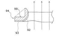
さらに、このベルマウス9には、平面部93と湾曲部92とにわたって設けられ、湾曲部92の外周縁の円周方向に交差する複数のリブ94が設けられている。リブ94は、平面部93の吹出し側表面および湾曲部の湾曲の内側表面から起立して設けられている。図7に、ベルマウス9のリブ94が設けられている部分の断面図を示す。リブ94は、その稜線99が平面部93および湾曲部92に近づくように凹んだ形状となっており、リブ94は、湾曲部92と平面部93との断面形状に概ね沿ったL字型形状となっている。
【0028】
[特徴]
(1)
この空気調和機1の室外機3では、図6に示すように、湾曲部92の吸込み側の外周縁から、径方向に略平行な平面部93が延設されている。このため、ベルマウス9へと吸い込まれる空気が湾曲部92の吸込み側の外周縁で巻き込まれることが抑えられる。従って、湾曲部92の吸込み側の外周縁での空気流の乱れが低減し、空気流による騒音が低減する。
【0029】
また、このような騒音の低減の効果は、平面部長さLと、湾曲部92の曲率半径Rとに関係し、平面部長さLの最大値Lmと、湾曲部92の曲率半径Rとの比Lm/Rが、0.5≦Lm/R≦1.5であることが望ましいことが本願の発明者によって明らかになっている。
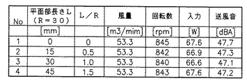
空気流による騒音の低減に関する試験条件および試験結果を図8から図10に示す。
【0030】
この試験では、図8に示すように、平面部長さLの異なる複数種類のベルマウス9について、それぞれのベルマウス9が備えられた室外機3の送風音の大きさが測定された。試験は、曲率半径R=30mmに対して平面部長さL=0,15,30,45mmの4種類のベルマウス9に対して行われた。なお、試験で用いられたベルマウス9の外縁は円形になっており、各ベルマウス9の平面部長さLは一定となっている。すなわち、平面部長さL=平面部長さの最大値Lmとなっている。また、各ベルマウス9について、ファンモータへの入力電力は略一定とされ、送風ファン8による風量は一定とされている。
【0031】
図9に試験結果を表すグラフ、図10に実験結果の表を示す。
図9および図10から分かるように、平面部93が設けられていないL/R=0の場合と比較すると、L/R==0.5,L/R=1,L/R=1.5のいずれの場合も送風音が低下している。また、L/R==0.5,L/R=1,L/R=1.5のなかでも、L/R=1の場合が最も送風音が低下している。
【0032】
上述したように、室外機3が備えるベルマウス9では、平面部長さLの最大値Lmと、湾曲部92の曲率半径Rとの比Lm/Rが、Lm/R=1となっている。このため、この室外機3では、空気流による騒音がより低減することが分かる。
(2)
ベルマウス9に平面部93が設けられると、図16に示すような平面部93をほとんど有さない従来のベルマウスと比べてベルマウス9の寸法が増大する。一方、空気調和機1の室外機3の小型化の観点からは、ベルマウス9の寸法の増大はできるだけ抑えられることが望ましい。
【0033】
この空気調和機1の室外機3では、平面部93は、湾曲部92の外周縁の円周方向の全部に設けられるのではなく、その一部に設けられている。このため、ベルマウス9の平面部93が、湾曲部92の外周縁よりも大きな円形の形状となっている場合よりも、ベルマウス9の寸法の増大が抑えられている。
また、平面部93は、開口を挟んで対向するように配置されている。このため、平面部93の各部分93a,93b,93c,93dの配置は概ね均等になっており、送風音の偏りが防止されている。
【0034】
(3)
ベルマウス9に平面部93が設けられる場合、補強のために湾曲部92と平面部93との表面にリブ94を設けることが望ましい。一方、ベルマウス9の周囲を流れる空気流は、ベルマウス9の表面に沿って流れることがある。すなわち、平面部93の吹出し側表面および湾曲部の湾曲の内側表面にも、空気流が流れる。そして、リブ94がこのような空気流の妨げとなると、空気流による騒音が発生し易くなる。
【0035】
しかし、この空気調和機1の室外機3では、リブ94は、平面部93の吹出し側表面および湾曲部92の湾曲の内側表面から起立して設けられ、その稜線99が平面部93および湾曲部92に近づくように凹んだ形状となっている。このため、リブ94が設けられている側の湾曲部92と平面部93とに沿って流れる空気流がリブ94によって妨げられることが低減している。すなわち、湾曲部92と平面部93とにリブ94が設けられる場合には、リブの形状は、図7に二点鎖線で表すように、平面部93の吹出し側表面および湾曲部92の湾曲の内側表面を最短で繋ぐ略三角形状となることが通常である。しかし、このような形状では、平面部93の吹出し側表面および湾曲部の湾曲の内側表面に沿って湾曲部92の円周方向に流れる空気流の妨げとなり易い。従って、空気流による騒音が増大する恐れがある。しかし、リブ94は、稜線が平面部93および湾曲部92に近づくように凹んだ形状となっているため、湾曲部92の円周方向に沿って流れる空気流の妨げとなる恐れが少なくなっている。これにより、リブ94が設けられることによる騒音の増大が抑制されている。
【0036】
<第2実施形態>
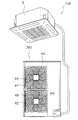
本発明の第2実施形態が採用された空気調和機100の室外機300の外観を図11に示す。空気調和機100は、第1実施形態にかかる空気調和機1と同様に、室内に配置される室内機2と、室外に配置される室外機300とに分かれたセパレート型の空気調和機100であるが、室外機300は、内部に、第1回転軸を有する第1送風ファン81と、第2回転軸を有する第2送風ファン82との2つの送風ファンを備えている。そして、室外機300の前板46には、第1吹出し口47と第2吹出し口48との2つの吹出し口が設けられている。第1送風ファン81と第2送風ファン82とは、上下に並んで第1回転軸と第2回転軸とが平行になるように配置されており、第1吹出し口47と第2吹出し口48とは、第1送風ファン81と第2送風ファン82とに対応して上下に並んで配置されている。
【0037】
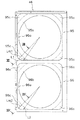
図12に、第1ベルマウス95と第2ベルマウス96とが取り付けられた状態の前板46を背面側から見た図を示す。
第1ベルマウス95と第2ベルマウス96とは、それぞれ第1実施形態にかかるベルマウス9と同様の形状を有しており、それぞれ第1吹出し口47と第2吹出し口48とに対応して上下に並んで取り付けられている。第1ベルマウス95は、第1円筒部95aと第1湾曲部95bと第1平面部95cとを有している。第2ベルマウス96は、第2円筒部96aと第2湾曲部96bと第2平面部96cとを有している。第1円筒部95aと第2円筒部96aとは、第1実施形態にかかるベルマウス9の円筒部91と同様の形状であり、第1湾曲部95bと第2湾曲部96bとは湾曲部92と同様の形状であり、第1平面部95cと第2平面部96cとは平面部93と同様の形状となっている。また、第1ベルマウス95の外縁および前記第2ベルマウス96の外縁は、それぞれ略四角形に形成されており、第1ベルマウス95と第2ベルマウス96とは、それぞれの外縁の辺が対向して近接するように配置されている。すなわち、第1平面部95cが設けられていない第1湾曲部95bの直線部分と、第2平面部96cが設けられていない第2湾曲部96bの直線部分とが近接するように、第1ベルマウス95と第2ベルマウス96とは配置されている。
【0038】
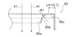
図13に第1ベルマウス95の断面図を、図14に第2ベルマウス96の断面図を示す。
第1回転軸を端部とする半平面で第1平面部95cを切った断面における第1平面部95cの長さを表す第1平面部長さL1の最大値Lm1と、第1湾曲部95bの曲率半径R1との比Lm1/R1が、Lm1/R1=1となっている。また、第2回転軸を端部とする半平面で第2平面部96cを切った断面における第2平面部96cの長さを表す第2平面部長さL2の最大値Lm2と、第2湾曲部96bの曲率半径R2との比Lm2/R2が、Lm2/R2=1となっている。
【0039】
[特徴]
この空気調和機100の室外機300では、第1湾曲部95bの吸込み側の外周縁から、径方向に略平行な第1平面部95cが延設されている。また、第2湾曲部96bの吸込み側の外周縁から、径方向に略平行な第2平面部96cが延設されている。そして、第1平面部長さL1の最大値Lm1と、第1湾曲部95bの曲率半径R1との比Lm1/R1=1であり、第2平面部長さL2の最大値Lm2と、第2湾曲部96bの曲率半径R2との比Lm2/R2=1となっている。このため、第1実施形態にかかる空気調和機1の室外機3と同様に、空気流による騒音が低減されている。
【0040】
また、第1ベルマウス95と第2ベルマウス96とが並設される場合、空気調和機100の室外機300の大型化を抑制するという観点からは、第1ベルマウス95と第2ベルマウス96とは近接して配置されることが望ましい。しかし、もし、第1平面部95cと第2平面部96cとがそれぞれ第1湾曲部95bと第2湾曲部96bとの全周を覆うように設けられる場合には、第1ベルマウス95と第2ベルマウス96との近接部分で第1平面部95cと第2平面部96cとが重なる恐れがある。従って、第1平面部95cと第2平面部96cとが重ならないように第1ベルマウス95と第2ベルマウス96との距離を隔てて配置することが必要となる。このため、空気調和機100の室外機300が大型化する恐れがある。
【0041】
しかし、この空気調和機100の室外機300では、第1平面部95cが設けられていない第1湾曲部95bの直線部分と、第2平面部96cが設けられていない第2湾曲部96bの直線部分とが近接するように、第1ベルマウス95と第2ベルマウス96とが配置されている。すなわち、第1ベルマウス95と第2ベルマウス96とにおいては、第1平面部95cと第2平面部96cとが、第1湾曲部95bと第2湾曲部96bとが近接する部分近傍を除いて設けられている。このため、第1平面部95cと第2平面部96cとが、第1ベルマウス95と第2ベルマウス96とを近接させて設ける際の妨げとならない。従って、第1ベルマウス95と第2ベルマウス96とを近接して配置することができる。これにより、空気調和機100の室外機300の大型化が抑制されている。
【0042】
<他の実施形態>
(1)
上記の第1実施形態では、平面部93は、湾曲部92の外周縁の4つの円弧状の部分からそれぞれ延設されている。すなわち、平面部93は、湾曲部92の外周縁の円周方向の全部に設けられるのではなく、その一部に設けられている。しかし、室外機3の内部の設置空間に余裕がある場合等には、湾曲部92の外周縁の円周方向の全部に平面部93が設けられてもよい。これによっても、空気流による騒音がより低減する。
【0043】
また、上記の第1実施形態では、ベルマウス9の外縁が四角形状となるように、平面部長さLが変化しているが、騒音の低減という観点からは、径方向長さLが一定となってもよい。すなわち、平面部93の外縁が円弧状、あるいは円形になっていてもよい。さらに、ベルマウス9の外縁が四角形状以外の多角形状となるように、平面部長さLが変化していてもよい。これらの場合も、平面部93が存在することにより、空気流の乱れを抑えて騒音を抑制することができる。
【0044】
(2)
上記の第1実施形態では、平面部長さLの最大値Lmと、湾曲部92の曲率半径Rとの比Lm/Rが、Lm/R=1となっている。また、上記の第2実施形態では、第1平面部長さL1の最大値Lm1と、第1湾曲部95bの曲率半径R1との比Lm1/R1=1であり、第2平面部長さL2の最大値Lm2と、第2湾曲部96bの曲率半径R2との比Lm2/R2=1となっている。上述した試験結果から分かるように、より望ましいのは上記のようなLm/R=1、Lm1/R1=1およびLm2/R2=1の場合であるが、0.5≦Lm/R≦1.5、0.5≦Lm1/R1≦1.5および0.5≦Lm2/R2≦1.5の範囲内であれば、空気流による騒音の低減の効果は十分に得られる。
【0045】
(3)
ベルマウス9の外縁の形状は四角形状に限らず、四角以外の多角形でもよい。また、第1ベルマウス95の第1湾曲部95bと第2ベルマウス96の第2湾曲部96bとには、それぞれ4つの直線部分が設けられているが、第1ベルマウス95と第2ベルマウス96との近接部分のみが直線上になっており、他の部分は円弧状に形成されていてもよい。この場合でも、第1ベルマウス95と第2ベルマウス96とを近接させて配置することができ、室外機3の大型化を抑制することができる。
【0046】
(4)
上記の第2実施形態では、第1ベルマウス95と第2ベルマウス96とが上下に2つ配置されているが、第1ベルマウス95と第2ベルマウス96との配置は上下に限られるものではない。第1送風ファン81と第2送風ファン82とが左右に配置されるのであれば、第1送風ファン81と第2送風ファン82との配置に合わせて第1ベルマウス95と第2ベルマウス96とが左右に並んで配置されてもよい。
【0047】
また、第1ベルマウス95と第2ベルマウス96とに加えて、さらに第3ベルマウスや第4ベルマウスなど、複数のベルマウスが追加されてもよい。
(5)
上記の第1実施形態では、ベルマウス9の開口は円形の形状となっており、湾曲部92も円形の開口を構成しているが、四角形や六角形などの多角形や楕円形など、他の形状の開口がベルマウス9に設けられてもよい。
【0048】
第2実施形態にかかる第1湾曲部95bおよび第2湾曲部96bについても同様である。
(6)
上記の第1実施形態では、平面部93が径方向に平行になっているが、平面部93は、湾曲部92の外縁から延設されていればよく、必ずしも径方向に平行になっていなくてもよい。
【0049】
第2実施形態にかかる第1平面部95cおよび第2平面部96cについても同様である。
【0050】
【発明の効果】
請求項1に記載の空気調和機の室外機では、湾曲部の吸込み側の外縁の少なくとも一部から平面部が延設されている。このため、ベルマウスへと吸い込まれる空気が湾曲部の吸込み側の外縁で巻き込まれることが平面部によって抑えられる。従って、湾曲部の吸込み側の外縁近傍での空気流の乱れを低減することができ、空気流による騒音を低減することができる。また、このような騒音の低減の効果は、平面部長さLと、湾曲部の曲率半径Rとに関係し、平面部長さLの最大値Lmと、湾曲部の曲率半径Rとの比Lm/Rが、0.5≦Lm/R≦1.5であることが望ましいことが、本願の発明者によって明らかになった。そして、この空気調和機の室外機は、この条件に適合するベルマウスを備えるため、空気流による騒音をより低減することができる。
【0051】
請求項2に記載の空気調和機の室外機では、平面部は、開口を挟んで対向するように設けられる。このため、この空気調和機の室外機では、送風音の偏りを低減することができる。
請求項3に記載の空気調和機の室外機では、リブは、平面部の吹出し側表面および湾曲部の湾曲の内側表面から起立しており、リブの稜線が平面部および湾曲部に近づくように凹んでいる。このため、リブが設けられている側の湾曲部と平面部との表面に沿って流れる空気流がリブによって妨げられることが低減している。これにより、この空気調和機の室外機では、リブによって騒音が生じる恐れを低減することができる。
【0052】
請求項4に記載の空気調和機の室外機では、第1湾曲部の吸込み側の外縁の少なくとも一部から第1平面部が延設される。また、第2湾曲部の吸込み側の外縁の少なくとも一部から第2平面部が延設される。このため、第1ベルマウスや第2ベルマウスへと吸い込まれる空気が第1湾曲部や第2湾曲部の吸込み側の外縁近傍で巻き込まれることが抑えられる。従って、第1湾曲部や第2湾曲部の吸込み側の外縁での空気流の乱れを低減することができ、空気流による騒音を低減することができる。また、このような騒音の低減の効果は、第1平面部長さL1と、第1湾曲部の曲率半径R1とに関係し、第1平面部長さL1の最大値Lm1と、第1湾曲部の曲率半径R1との比Lm1/R1が、0.5≦Lm1/R1≦1.5であることが望ましく、同様に、第2平面部長さL2の最大値Lm2と、第2湾曲部の曲率半径R2との比Lm2/R2が、0.5≦Lm2/R2≦1.5であることが望ましいことが、本願の発明者によって明らかになった。そして、この空気調和機の室外機は、この条件の第1ベルマウスおよび第2ベルマウスを備えるため、空気流による騒音をより低減することができる。
【0053】
また、第1ベルマウスと第2ベルマウスとが並設される場合、空気調和機の室外機の大型化を抑制するという観点からは、第1ベルマウスと第2ベルマウスとは近接して配置されることが望ましい。
この空気調和機の室外機では、第1平面部と第2平面部とは、第1湾曲部と第2湾曲部とが近接する部分近傍を除いて設けられる。このため、第1平面部と第2平面部とが第1ベルマウスと第2ベルマウスとを近接させて設ける際の妨げとなる恐れが少ない。これにより、第1ベルマウスと第2ベルマウスとを近接させて設けることが容易になっており、空気調和機の室外機の大型化を抑制することができる。
【0054】
請求項5に記載の空気調和機の室外機では、第1ベルマウスの外縁および第2ベルマウスの外縁が略四角形に形成されている。このため、第1ベルマウスと第2ベルマウスとが並設される場合でも、ベルマウスの平面部の間に隙間が生じ難くなっている。
【図面の簡単な説明】
【図1】第1実施形態にかかる空気調和機の外観図。
【図2】室外機の側面断面図。
【図3】前板の正面図。
【図4】ベルマウスの正面図。
【図5】ベルマウスの左側面図。
【図6】ベルマウスの断面図。
【図7】リブ近傍のベルマウスの断面図。
【図8】騒音低減効果試験の試験条件を表す図。
【図9】騒音低減効果試験の試験結果のグラフ。
【図10】騒音低減効果試験の試験結果の表。
【図11】第2実施形態にかかる空気調和機の外観図。
【図12】前板、第1ベルマウスおよび第2ベルマウスの正面図(背面側)。
【図13】第1ベルマウスの断面図。
【図14】第2ベルマウスの断面図。
【図15】従来のベルマウスの正面図。
【図16】従来のベルマウスの断面図。
【符号の説明】
1,100 空気調和機
3,300 室外機
8 送風ファン
9 ベルマウス
81 第1送風ファン
82 第2送風ファン
92 湾曲部
93 平面部
94 リブ
95 第1ベルマウス
95b 第1湾曲部
95c 第1平面部
96 第2ベルマウス
96b 第2湾曲部
96c 第2平面部[0001]
TECHNICAL FIELD OF THE INVENTION
The present invention relates to an outdoor unit of an air conditioner, particularly to an outdoor unit of an air conditioner including a bell mouth.
[0002]
[Prior art]
The outdoor unit of the air conditioner is provided with a blower fan, and the blower fan generates an airflow that is taken into the outdoor unit and blows out to the outside of the outdoor unit again. A bell mouth as shown in FIG. 15 is provided near the outlet of the air blown out of the outdoor unit, and a flow path of the air blown out to the outdoor is often formed. The airflow generated by the blower fan passes through the bell mouth, and at this time, noise may be generated due to the airflow. For this reason, a bell mouth in which a curved portion is provided on the suction side of the airflow has conventionally been devised (see Patent Document 1). The curved portion of the bell mouth forms an opening through which the air flow generated by the blower fan passes, and as shown in FIG. 16, is curved with a radius of curvature R such that the opening becomes wider as approaching the air flow suction side. ing. In FIG. 14, the right side is the suction side, and the left side is the outlet side.
[0003]
Since such a curved portion constitutes the outer edge of the bell mouth on the suction side, the air flow can smoothly pass through the bell mouth, and noise due to the air flow is reduced.
[0004]
[Patent Document 1]
Japanese Patent Application Laid-Open No. 11-14101 (FIGS. 1 (b) and 1 (c))
[0005]
[Problems to be solved by the invention]
Since the curved portion forms the outer edge of the bell mouth on the suction side, noise due to airflow is reduced. However, for a user of the air conditioner, it is desirable that such noise be further reduced.
An object of the present invention is to provide an outdoor unit of an air conditioner that can further reduce noise generated by an air flow.
[0006]
[Means for Solving the Problems]
The outdoor unit of the air conditioner according to
[0007]
In this outdoor unit of the air conditioner, the flat portion extends from at least a part of the outer edge on the suction side of the curved portion. For this reason, the air sucked into the bell mouth is prevented from being caught at the outer edge on the suction side of the curved portion by the flat portion. Therefore, turbulence of the air flow near the outer edge on the suction side of the curved portion can be reduced, and noise due to the air flow can be reduced. The effect of such noise reduction is related to the length L of the flat portion and the radius of curvature R of the curved portion, and the ratio Lm / the maximum value Lm of the length L of the flat portion to the radius of curvature R of the bent portion. It has been clarified by the present inventor that R is desirably 0.5 ≦ Lm / R ≦ 1.5. And since the outdoor unit of this air conditioner is provided with a bell mouth meeting this condition, it is possible to further reduce the noise due to the airflow.
[0008]
An outdoor unit of an air conditioner according to a second aspect is the outdoor unit of the air conditioner according to the first aspect, wherein the flat portions are provided to face each other with the opening interposed therebetween.
In this outdoor unit of the air conditioner, the flat portions are provided to face each other with the opening interposed therebetween. For this reason, in the outdoor unit of the air conditioner, it is possible to reduce the bias of the blowing sound.
[0009]
An outdoor unit of an air conditioner according to a third aspect is the outdoor unit of the air conditioner according to the first or second aspect, wherein the bellmouth has a rib provided over a flat portion and a curved portion. The rib rises from the outlet side surface of the flat portion and the inner surface of the curved portion of the curved portion, and is recessed so that the ridge line of the rib approaches the flat portion and the curved portion.
[0010]
When the bell mouth is provided with a flat portion, it is desirable to provide a rib over the curved portion and the flat portion for reinforcement. However, when the ribs hinder the air flow, noise due to the air flow is likely to occur.
In this outdoor unit of the air conditioner, the rib stands up from the outlet side surface of the flat portion and the inner surface of the curved portion of the curved portion, and the ridge of the rib is recessed so as to approach the flat portion and the curved portion. For this reason, it is reduced that the airflow flowing along the surface of the curved portion and the flat portion on the side where the rib is provided is obstructed by the rib. Thereby, in the outdoor unit of the air conditioner, the risk of noise caused by the ribs can be reduced.
[0011]
The outdoor unit of the air conditioner according to
[0012]
In the outdoor unit of the air conditioner, the first plane portion extends from at least a part of the outer edge on the suction side of the first curved portion. Further, the second flat portion extends from at least a part of the outer edge on the suction side of the second curved portion. For this reason, the air sucked into the first bell mouth and the second bell mouth is suppressed from being caught in the vicinity of the outer edge on the suction side of the first curved portion and the second curved portion. Therefore, it is possible to reduce the turbulence of the airflow at the outer edge of the first bending portion and the second bending portion on the suction side, and it is possible to reduce the noise due to the airflow. The effect of such noise reduction is related to the first plane portion length L1 and the curvature radius R1 of the first curved portion, and the maximum value Lm1 of the first plane portion length L1 and the first curved portion It is desirable that the ratio Lm1 / R1 to the radius of curvature R1 is 0.5 ≦ Lm1 / R1 ≦ 1.5. Similarly, the maximum value Lm2 of the length L2 of the second plane portion and the radius of curvature of the second curved portion The inventors of the present application have clarified that the ratio Lm2 / R2 to R2 is desirably 0.5 ≦ Lm2 / R2 ≦ 1.5. Since the outdoor unit of the air conditioner includes the first bellmouth and the second bellmouth under this condition, it is possible to further reduce the noise due to the airflow.
[0013]
When the first bellmouth and the second bellmouth are arranged side by side, the first bellmouth and the second bellmouth are close to each other from the viewpoint of suppressing an increase in the size of the outdoor unit of the air conditioner. It is desirable to be arranged.
In the outdoor unit of the air conditioner, the first plane portion and the second plane portion are provided except for the vicinity of a portion where the first curved portion and the second curved portion are close to each other. For this reason, there is little possibility that the first flat portion and the second flat portion may hinder the first bell mouth and the second bell mouth from being provided close to each other. Accordingly, it is easy to provide the first bellmouth and the second bellmouth in close proximity, and it is possible to suppress an increase in the size of the outdoor unit of the air conditioner.
[0014]
An outdoor unit of an air conditioner according to a fifth aspect is the outdoor unit of the air conditioner according to the fourth aspect, wherein an outer edge of the first bellmouth and an outer edge of the second bellmouth are formed in a substantially square shape. I have.
When the first bellmouth and the second bellmouth are arranged side by side, if the first bellmouth and the second bellmouth are circular, a gap is formed between the first bellmouth and the second bellmouth. Easy to occur.
[0015]
However, in the outdoor unit of the air conditioner, the outer edge of the first bellmouth and the outer edge of the second bellmouth are formed in a substantially rectangular shape. For this reason, even when the first bellmouth and the second bellmouth are arranged side by side, a gap is hardly generated between the flat portions of the bellmouth.
[0016]
BEST MODE FOR CARRYING OUT THE INVENTION
<First embodiment>
[overall structure]
FIG. 1 shows the appearance of an
[0017]
[Schematic configuration of outdoor unit]
The
The ventilation chamber SP1 located on the left side is a space in which an outdoor heat exchanger is arranged and through which air exchanged with heat through the outdoor heat exchanger passes. A
[0018]
The machine room SP2 located on the right side is a space somewhat isolated from the ventilation room SP1, and houses a compressor, a four-way switching valve, electrical components, and the like.
As shown in FIG. 2, an
[0019]
The
[0020]
[Configuration of Front Plate 40]
FIG. 3 shows a front view of the
The
The front plate
[0021]
As shown in FIG. 2, the
[0022]
[Configuration of Bellmouth 9]
FIG. 4 is a front view of the
The
[0023]
The
[0024]
The
[0025]
As shown in FIG. 4, the
[0026]
Further, the plane portion length L defined by the length of the
[0027]
In the present embodiment, the
Further, the
[0028]
[Characteristic]
(1)
In the
[0029]
The effect of the noise reduction is related to the length L of the flat portion and the radius of curvature R of the
FIGS. 8 to 10 show test conditions and test results relating to reduction of noise due to airflow.
[0030]
In this test, as shown in FIG. 8, for a plurality of types of
[0031]
FIG. 9 is a graph showing test results, and FIG. 10 is a table showing experimental results.
As can be seen from FIGS. 9 and 10, as compared with the case where L / R = 0 where the
[0032]
As described above, in the
(2)
When the
[0033]
In the
The
[0034]
(3)
When the
[0035]
However, in the
[0036]
<Second embodiment>
FIG. 11 shows the appearance of an
[0037]
FIG. 12 shows a view of the
The
[0038]
FIG. 13 is a sectional view of the
The maximum value Lm1 of the first flat portion length L1 representing the length of the first
[0039]
[Characteristic]
In the
[0040]
Further, when the
[0041]
However, in the
[0042]
<Other embodiments>
(1)
In the above-described first embodiment, the
[0043]
Further, in the above-described first embodiment, the length L of the flat portion is changed so that the outer edge of the
[0044]
(2)
In the first embodiment, the ratio Lm / R of the maximum value Lm of the length L of the plane portion to the radius of curvature R of the
[0045]
(3)
The shape of the outer edge of the
[0046]
(4)
In the above-described second embodiment, two
[0047]
Further, in addition to the
(5)
In the above-described first embodiment, the opening of the
[0048]
The same applies to the
(6)
In the above-described first embodiment, the
[0049]
The same applies to the first
[0050]
【The invention's effect】
In the outdoor unit of the air conditioner according to the first aspect, the plane portion extends from at least a part of the outer edge on the suction side of the curved portion. For this reason, the air sucked into the bell mouth is prevented from being caught at the outer edge on the suction side of the curved portion by the flat portion. Therefore, turbulence of the air flow near the outer edge on the suction side of the curved portion can be reduced, and noise due to the air flow can be reduced. The effect of such noise reduction is related to the length L of the flat portion and the radius of curvature R of the curved portion, and the ratio Lm / the maximum value Lm of the length L of the flat portion to the radius of curvature R of the bent portion. It has been clarified by the present inventor that R is desirably 0.5 ≦ Lm / R ≦ 1.5. And since the outdoor unit of this air conditioner is provided with a bell mouth meeting this condition, it is possible to further reduce the noise due to the airflow.
[0051]
In the outdoor unit of the air conditioner according to
In the outdoor unit of the air conditioner according to the third aspect, the rib stands up from the blow-out surface of the flat portion and the inner surface of the curved portion of the curved portion so that the ridge line of the rib approaches the flat portion and the curved portion. It is concave. For this reason, it is reduced that the airflow flowing along the surface of the curved portion and the flat portion on the side where the rib is provided is obstructed by the rib. Thereby, in the outdoor unit of the air conditioner, the risk of noise caused by the ribs can be reduced.
[0052]
In the outdoor unit of the air conditioner according to the fourth aspect, the first plane portion extends from at least a part of the outer edge on the suction side of the first curved portion. Further, the second flat portion extends from at least a part of the outer edge on the suction side of the second curved portion. For this reason, the air sucked into the first bell mouth and the second bell mouth is suppressed from being caught in the vicinity of the outer edge on the suction side of the first curved portion and the second curved portion. Therefore, it is possible to reduce the turbulence of the airflow at the outer edge of the first bending portion and the second bending portion on the suction side, and it is possible to reduce the noise due to the airflow. The effect of such noise reduction is related to the first plane portion length L1 and the curvature radius R1 of the first curved portion, and the maximum value Lm1 of the first plane portion length L1 and the first curved portion It is desirable that the ratio Lm1 / R1 to the radius of curvature R1 is 0.5 ≦ Lm1 / R1 ≦ 1.5. Similarly, the maximum value Lm2 of the length L2 of the second plane portion and the radius of curvature of the second curved portion The inventors of the present application have clarified that the ratio Lm2 / R2 to R2 is desirably 0.5 ≦ Lm2 / R2 ≦ 1.5. Since the outdoor unit of the air conditioner includes the first bellmouth and the second bellmouth under this condition, it is possible to further reduce the noise due to the airflow.
[0053]
When the first bellmouth and the second bellmouth are arranged side by side, the first bellmouth and the second bellmouth are close to each other from the viewpoint of suppressing an increase in the size of the outdoor unit of the air conditioner. It is desirable to be arranged.
In the outdoor unit of the air conditioner, the first plane portion and the second plane portion are provided except for the vicinity of a portion where the first curved portion and the second curved portion are close to each other. For this reason, there is little possibility that the first flat portion and the second flat portion may hinder the first bell mouth and the second bell mouth from being provided close to each other. Accordingly, it is easy to provide the first bellmouth and the second bellmouth in close proximity, and it is possible to suppress an increase in the size of the outdoor unit of the air conditioner.
[0054]
In the outdoor unit of the air conditioner according to the fifth aspect, the outer edge of the first bellmouth and the outer edge of the second bellmouth are formed in a substantially rectangular shape. For this reason, even when the first bellmouth and the second bellmouth are arranged side by side, a gap is hardly generated between the flat portions of the bellmouth.
[Brief description of the drawings]
FIG. 1 is an external view of an air conditioner according to a first embodiment.
FIG. 2 is a side sectional view of the outdoor unit.
FIG. 3 is a front view of a front plate.
FIG. 4 is a front view of a bellmouth.
FIG. 5 is a left side view of the bellmouth.
FIG. 6 is a sectional view of a bell mouth.
FIG. 7 is a cross-sectional view of a bell mouth near a rib.
FIG. 8 is a diagram showing test conditions of a noise reduction effect test.
FIG. 9 is a graph showing test results of a noise reduction effect test.
FIG. 10 is a table showing test results of a noise reduction effect test.
FIG. 11 is an external view of an air conditioner according to a second embodiment.
FIG. 12 is a front view (rear side) of the front plate, the first bell mouth, and the second bell mouth.
FIG. 13 is a sectional view of a first bellmouth.
FIG. 14 is a sectional view of a second bellmouth.
FIG. 15 is a front view of a conventional bell mouth.
FIG. 16 is a sectional view of a conventional bell mouth.
[Explanation of symbols]
1,100 air conditioner
3,300 outdoor unit
8 blower fan
9 Bellmouth
81 First blower fan
82 Second blower fan
92 Bending part
93 flat part
94 rib
95 1st Bellmouth
95b 1st bending part
95c 1st plane part
96 Second Bellmouth
96b 2nd bending part
96c 2nd flat part
Claims (5)
前記送風ファン(8)によって前記回転軸方向に生じる空気流が通る開口を構成し前記空気流の吸込み側へと近づくにつれて前記開口が広がるように曲率半径Rで湾曲する湾曲部(92)と、前記湾曲部(92)の吸込み側の外縁の少なくとも一部から延設される平面部(93)とを有するベルマウス(9)と、
を備え、
前記回転軸を端部とする半平面で前記平面部(93)を切った断面における前記平面部(93)の長さを表す平面部長さLの最大値Lmと、前記湾曲部(92)の曲率半径Rとの比Lm/Rが、0.5≦Lm/R≦1.5である、
空気調和機の室外機。A blower fan (8) having a rotating shaft;
A curved portion (92) that forms an opening through which the airflow generated by the blower fan (8) in the direction of the rotation axis passes and that has a radius of curvature R such that the opening widens toward the suction side of the airflow; A bell mouth (9) having a flat portion (93) extending from at least a portion of the suction-side outer edge of the curved portion (92);
With
A maximum value Lm of a plane portion length L representing a length of the plane portion (93) in a cross section obtained by cutting the plane portion (93) with a half plane having the rotation axis as an end, and a curved portion (92). The ratio Lm / R to the radius of curvature R is 0.5 ≦ Lm / R ≦ 1.5,
Outdoor unit of air conditioner.
請求項1に記載の空気調和機の室外機。The flat portion (93) is provided so as to face the opening.
The outdoor unit of the air conditioner according to claim 1.
請求項1または2に記載の空気調和機の室外機。The bell mouth (9) is provided over the flat portion (93) and the curved portion (92), and stands up from the blow-out side surface of the flat portion (93) and the curved inner surface of the curved portion (92). A rib (94) recessed so that the ridgeline approaches the flat portion (93) and the curved portion (92);
The outdoor unit of the air conditioner according to claim 1 or 2.
前記第1送風ファン(81)によって前記第1回転軸方向に生じる空気流が通る開口を構成し前記空気流の吸込み側へと近づくにつれて前記開口が広がるように曲率半径R1で湾曲する第1湾曲部(95b)と、前記第1湾曲部(95b)の吸込み側の外縁の少なくとも一部から延設される第1平面部(95c)とを有する第1ベルマウス(95)と、
前記第1送風ファン(81)と並んで設けられ、第2回転軸を有する第2送風ファン(82)と、
前記第2送風ファン(82)によって前記第2回転軸方向に生じる空気流が通る開口を構成し前記空気流の吸込み側へと近づくにつれて前記開口が広がるように曲率半径R2で湾曲する第2湾曲部(96b)と、前記第2湾曲部(96b)の吸込み側の外縁の少なくとも一部から延設される第2平面部(96c)とを有し、前記第1ベルマウス(95)と並んで設けられる第2ベルマウス(96)と、
を備え、
前記第1回転軸を端部とする半平面で前記第1平面部(95c)を切った断面における前記第1平面部(95c)の長さを表す第1平面部長さL1の最大値Lm1と、前記第1湾曲部(95b)の曲率半径R1との比Lm1/R1が、0.5≦Lm1/R1≦1.5であり、
前記第2回転軸を端部とする半平面で前記第2平面部(96c)を切った断面における前記第2平面部(96c)の長さを表す第2平面部長さL2の最大値Lm2と、前記第2湾曲部(96b)の曲率半径R2との比Lm2/R2が、0.5≦Lm2/R2≦1.5であり、
前記第1平面部(95c)と前記第2平面部(96c)とは、前記第1湾曲部(95b)と前記第2湾曲部(96b)とが近接する部分近傍を除いて設けられる、
空気調和機の室外機。A first blower fan (81) having a first rotation axis;
A first curved portion that forms an opening through which an air flow generated by the first blower fan (81) in the first rotation axis direction passes and that has a radius of curvature R1 such that the opening becomes wider as approaching the air flow suction side; A first bell mouth (95) having a portion (95b) and a first flat portion (95c) extending from at least a part of an outer edge on the suction side of the first curved portion (95b);
A second blower fan (82) provided alongside the first blower fan (81) and having a second rotation axis;
A second curved portion configured to form an opening through which an air flow generated in the second rotation axis direction by the second blower fan passes, and to have a radius of curvature R2 such that the opening is widened toward the suction side of the air flow; (96b), and a second flat portion (96c) extending from at least a part of the suction side outer edge of the second curved portion (96b), and is arranged alongside the first bell mouth (95). A second bell mouth (96) provided by
With
A maximum value Lm1 of a first plane portion length L1 representing a length of the first plane portion (95c) in a cross section obtained by cutting the first plane portion (95c) with a half plane having the first rotation axis as an end; A ratio Lm1 / R1 with respect to the radius of curvature R1 of the first curved portion (95b) is 0.5 ≦ Lm1 / R1 ≦ 1.5;
A maximum value Lm2 of a second plane portion length L2 representing a length of the second plane portion (96c) in a cross section obtained by cutting the second plane portion (96c) with a half plane having the second rotation axis as an end; A ratio Lm2 / R2 of the second curved portion (96b) to the radius of curvature R2 is 0.5 ≦ Lm2 / R2 ≦ 1.5;
The first flat portion (95c) and the second flat portion (96c) are provided except for a portion near the first bent portion (95b) and the second bent portion (96b),
Outdoor unit of air conditioner.
請求項4に記載の空気調和機の室外機。An outer edge of the first bell mouth (95) and an outer edge of the second bell mouth (96) are formed in a substantially square shape.
An outdoor unit of the air conditioner according to claim 4.
Priority Applications (2)
| Application Number | Priority Date | Filing Date | Title |
|---|---|---|---|
| JP2002382588A JP2004211971A (en) | 2002-12-27 | 2002-12-27 | Outdoor unit of air conditioner |
| CN 03242751 CN2700746Y (en) | 2002-12-27 | 2003-03-28 | Outdoor machine of air conditioner |
Applications Claiming Priority (1)
| Application Number | Priority Date | Filing Date | Title |
|---|---|---|---|
| JP2002382588A JP2004211971A (en) | 2002-12-27 | 2002-12-27 | Outdoor unit of air conditioner |
Publications (1)
| Publication Number | Publication Date |
|---|---|
| JP2004211971A true JP2004211971A (en) | 2004-07-29 |
Family
ID=32818101
Family Applications (1)
| Application Number | Title | Priority Date | Filing Date |
|---|---|---|---|
| JP2002382588A Pending JP2004211971A (en) | 2002-12-27 | 2002-12-27 | Outdoor unit of air conditioner |
Country Status (2)
| Country | Link |
|---|---|
| JP (1) | JP2004211971A (en) |
| CN (1) | CN2700746Y (en) |
Cited By (5)
| Publication number | Priority date | Publication date | Assignee | Title |
|---|---|---|---|---|
| JP2006118722A (en) * | 2004-10-19 | 2006-05-11 | Hitachi Ltd | Air conditioner outdoor unit |
| JP2007003134A (en) * | 2005-06-27 | 2007-01-11 | Matsushita Electric Ind Co Ltd | Air conditioner cooling device |
| CN1884930B (en) * | 2005-06-23 | 2010-06-02 | 三星电子株式会社 | Air purifier |
| EP2333435A2 (en) | 2009-11-27 | 2011-06-15 | Sanyo Electric Co., Ltd. | Bell-mouth structure of air blower |
| JP2021162172A (en) * | 2020-03-30 | 2021-10-11 | 株式会社富士通ゼネラル | Outdoor unit of air conditioner |
-
2002
- 2002-12-27 JP JP2002382588A patent/JP2004211971A/en active Pending
-
2003
- 2003-03-28 CN CN 03242751 patent/CN2700746Y/en not_active Expired - Lifetime
Cited By (5)
| Publication number | Priority date | Publication date | Assignee | Title |
|---|---|---|---|---|
| JP2006118722A (en) * | 2004-10-19 | 2006-05-11 | Hitachi Ltd | Air conditioner outdoor unit |
| CN1884930B (en) * | 2005-06-23 | 2010-06-02 | 三星电子株式会社 | Air purifier |
| JP2007003134A (en) * | 2005-06-27 | 2007-01-11 | Matsushita Electric Ind Co Ltd | Air conditioner cooling device |
| EP2333435A2 (en) | 2009-11-27 | 2011-06-15 | Sanyo Electric Co., Ltd. | Bell-mouth structure of air blower |
| JP2021162172A (en) * | 2020-03-30 | 2021-10-11 | 株式会社富士通ゼネラル | Outdoor unit of air conditioner |
Also Published As
| Publication number | Publication date |
|---|---|
| CN2700746Y (en) | 2005-05-18 |
Similar Documents
| Publication | Publication Date | Title |
|---|---|---|
| US9513021B2 (en) | Blower and heat pump apparatus using the same | |
| CN108138798B (en) | Blower and air conditioner equipped with the blower | |
| CN110325745B (en) | Propeller fans, blowers and air conditioners | |
| JP4906555B2 (en) | Sirocco fan and air conditioner | |
| US7461518B2 (en) | Fan and air conditioner | |
| JP4876784B2 (en) | Double suction centrifugal blower | |
| JP2015081692A (en) | Indoor unit of air conditioner | |
| JP6709899B2 (en) | Blower fan and blower unit using the same | |
| JP5533969B2 (en) | Air conditioner | |
| WO2015040668A1 (en) | Air conditioner | |
| JP5293684B2 (en) | Air conditioner indoor unit | |
| JP2004211971A (en) | Outdoor unit of air conditioner | |
| TW200530539A (en) | Integral air conditioner | |
| WO2004088210A1 (en) | Outdoor unit for air conditioner | |
| JP2002048085A (en) | Impeller for multiple-type multi-blade blower, multiple-type multi-blade blower and air conditioner | |
| JP2007205268A (en) | Centrifugal fan | |
| WO2020152748A1 (en) | Fan blower, indoor unit, and air conditioner | |
| WO2019163450A1 (en) | Turbofan, and indoor unit for air conditioner | |
| JP4274229B2 (en) | Air conditioner | |
| JP2007285164A (en) | Sirocco fan and air conditioner | |
| JP2000213768A (en) | Air conditioning equipment | |
| JP4687741B2 (en) | Air conditioner | |
| JP2002022233A (en) | Air conditioner | |
| WO2018042689A1 (en) | Air conditioner | |
| JP2001221457A (en) | Refrigeration equipment |
Legal Events
| Date | Code | Title | Description |
|---|---|---|---|
| A621 | Written request for application examination |
Free format text: JAPANESE INTERMEDIATE CODE: A621 Effective date: 20051129 |
|
| A977 | Report on retrieval |
Effective date: 20080609 Free format text: JAPANESE INTERMEDIATE CODE: A971007 |
|
| A131 | Notification of reasons for refusal |
Effective date: 20080708 Free format text: JAPANESE INTERMEDIATE CODE: A131 |
|
| A02 | Decision of refusal |
Effective date: 20090203 Free format text: JAPANESE INTERMEDIATE CODE: A02 |