JP2004211835A - Thrust roller bearing - Google Patents
Thrust roller bearing Download PDFInfo
- Publication number
- JP2004211835A JP2004211835A JP2003000860A JP2003000860A JP2004211835A JP 2004211835 A JP2004211835 A JP 2004211835A JP 2003000860 A JP2003000860 A JP 2003000860A JP 2003000860 A JP2003000860 A JP 2003000860A JP 2004211835 A JP2004211835 A JP 2004211835A
- Authority
- JP
- Japan
- Prior art keywords
- roller bearing
- cages
- thrust roller
- thrust
- Prior art date
- Legal status (The legal status is an assumption and is not a legal conclusion. Google has not performed a legal analysis and makes no representation as to the accuracy of the status listed.)
- Pending
Links
Images


Classifications
-
- F—MECHANICAL ENGINEERING; LIGHTING; HEATING; WEAPONS; BLASTING
- F16—ENGINEERING ELEMENTS AND UNITS; GENERAL MEASURES FOR PRODUCING AND MAINTAINING EFFECTIVE FUNCTIONING OF MACHINES OR INSTALLATIONS; THERMAL INSULATION IN GENERAL
- F16C—SHAFTS; FLEXIBLE SHAFTS; ELEMENTS OR CRANKSHAFT MECHANISMS; ROTARY BODIES OTHER THAN GEARING ELEMENTS; BEARINGS
- F16C33/00—Parts of bearings; Special methods for making bearings or parts thereof
- F16C33/30—Parts of ball or roller bearings
- F16C33/46—Cages for rollers or needles
- F16C33/54—Cages for rollers or needles made from wire, strips, or sheet metal
- F16C33/542—Cages for rollers or needles made from wire, strips, or sheet metal made from sheet metal
- F16C33/547—Cages for rollers or needles made from wire, strips, or sheet metal made from sheet metal from two parts, e.g. two discs or rings joined together
-
- F—MECHANICAL ENGINEERING; LIGHTING; HEATING; WEAPONS; BLASTING
- F16—ENGINEERING ELEMENTS AND UNITS; GENERAL MEASURES FOR PRODUCING AND MAINTAINING EFFECTIVE FUNCTIONING OF MACHINES OR INSTALLATIONS; THERMAL INSULATION IN GENERAL
- F16C—SHAFTS; FLEXIBLE SHAFTS; ELEMENTS OR CRANKSHAFT MECHANISMS; ROTARY BODIES OTHER THAN GEARING ELEMENTS; BEARINGS
- F16C19/00—Bearings with rolling contact, for exclusively rotary movement
- F16C19/22—Bearings with rolling contact, for exclusively rotary movement with bearing rollers essentially of the same size in one or more circular rows, e.g. needle bearings
- F16C19/30—Bearings with rolling contact, for exclusively rotary movement with bearing rollers essentially of the same size in one or more circular rows, e.g. needle bearings for axial load mainly
Landscapes
- Engineering & Computer Science (AREA)
- General Engineering & Computer Science (AREA)
- Mechanical Engineering (AREA)
- Rolling Contact Bearings (AREA)
Abstract
Description
【0001】
【発明の属する技術分野】
この発明は、転動体として針状ころを用いたスラストころ軸受に関する。
【0002】
【従来の技術】
従来、スラストころ軸受において、図7に示すように2枚の略平行な環状の保持器23,24で針状ころ22を保持したものが知られている。これら2枚の保持器23,24は、図7(A)のように、その円周方向の複数箇所に保持器径方向に長いポケット25を有し、両保持器23,24の対応するポケット25,25にわたって針状ころ22が保持される。また、2枚の保持器23,24で、各針状ころ22の保持器軸方向への抜け出しが阻止される。
この種のスラストころ軸受は、対向する2枚のスラスト軌道輪(図示せず)間に、2枚の保持器23,24が回転可能となるように、各保持器23,24をそれぞれのスラスト軌道輪に対向させて設置する。このスラストころ軸受における保持器23,24の軸方向案内としては、針状ころ22で案内するもの(転動体案内)と、保持器23,24をスラスト軌道輪に接触させて軌道輪もたせとするもの(軌道輪案内)とがあり、針状ころ22のころ径が小径となるほど軌道輪案内とする場合が多い。
【0003】
【特許文献1】
特開2002−250347号公報
【0004】
【発明が解決しようとする課題】
しかし、従来のスラストころ軸受では、軌道輪案内とした場合に、スラスト軌道輪の軌道面に形成された油膜が、保持器23,24における隣接するポケット25,25間の柱部26で掻き取られて油膜切れが発生し、スラスト軌道輪および針状ころ22の摩耗が促進されてしまうことがある。その原因は、保持器23,24のポケット25を打ち抜き加工するときに、図7(B)のように各柱部26のエッジにバリ33が生じ、このバリ33がスラスト軌道輪の軌道面に形成された油膜を掻き取ってしまうからである。
従来、上記バリ33を除去するために化学研磨などを施しており、この処理である程度のバリ33の除去は可能であるが、バリ33が大きい場合にはエッジが残ってしまう。そのため、油膜形成能力を向上させる効果が十分でなく、満足できる潤滑性を確保することは困難である。
【0005】
この発明の目的は、ころの周面やスラスト軌道輪の軌道面に形成された油膜の状態を良好に保つことのできるスラストころ軸受を提供することである。
【0006】
【課題を解決するための手段】
この発明のスラストころ軸受は、複数の針状ころと、金属板の打ち抜き加工品からなる2枚の略平行な環状の保持器とを備え、これら2枚の保持器のそれぞれが円周方向の複数箇所にポケットを有し、上記各針状ころが上記2枚の保持器の対応するポケットに渡って入れられ、かつこれら2枚の保持器により、各針状ころの保持器軸方向の両側への抜け出しが阻止されたスラストころ軸受において、上記保持器の各ポケット間の柱部のエッジに、面取り部を設けたことを特徴とする。
この構成によると、保持器の各柱部のエッジに面取り部を設けたので、ポケットの打ち抜き加工により生じる柱部のエッジのバリを完全に除去することができ、スラスト軌道輪の軌道面に形成される油膜が、保持器柱部のバリで掻き取られることが防止される。そのため、スラスト軌道輪の軌道面における油膜切れが防止され、軸受本来の寿命を発揮させることができる。すなわちスラスト軌道輪の軌道面における油膜形成能力を一定に保ち、潤滑性の向上を図ることができる。
【0007】
上記面取り部の断面形状は、傾斜した直線状であっても、また凸曲線状であっても良い。面取り部の断面形状を傾斜した直線状とする場合は、面取り部の加工が容易で、ポンチ等で成形する場合にそのポンチの型面の形状が簡素になる。面取り部の断面形状を凸曲線状とすると、軌道面に形成される油膜の掻き取りがより確実に防止される。
【0008】
上記面取り部は、プレスによる潰し加工部分であっても良い。この潰し加工部分は、例えばポンチの型面を押し付けることで、角部を斜面または曲面に潰した部分である。ここで言う潰し加工は、面押し加工とも呼ばれる。
面取り部を潰し加工部分とすると、簡単な加工で確実に所定形状の面取り部を形成することができる。
【0009】
この発明において、上記面取り部は、保持器のポケットの打ち抜き加工時におけるバリ発生側の保持器表面におけるエッジのみに設けても良い。打ち抜き加工時における抜きだれ発生側の保持器表面は、面取り部を施さなくても、油膜掻き取りの問題が生じ難い。そのため片面だけの面取り部形成とすることで、製造工程の増加が低減でき、コスト増を抑えることができる。抜きだれ側となる面は、保持器のスラスト軌道輪との対向面側であっても、非対向面側であっても良い。
【0010】
この発明において、上記ポケットの長手方向に沿う内側面に、保持器両面に貫通する盗み溝を設けても良い。このように盗み溝を設けた場合、保持器内への油の流入が多くなり、潤滑性がさらに向上する。また、上記面取り部を潰し加工部分とする場合に、その潰し加工が容易に行える。特に、ポケットの内側面における長手方向の両端に上記盗み溝を設ける場合は、ポンチの潰し加工用の型面の両端が、ポケット内面の端面に当たらず、盗み溝の形成箇所に位置することになるため、潰し加工がより一層容易に、かつ綺麗に行える。
【0011】
さらに、これらの発明のいずれかにおいて、上記2枚の保持器は内周部および外周部のいずれか片方または両方で、互いに結合されたものとしても良い。このように結合した場合は、2枚の保持器相互の円周方向や軸方向の位置ずれが無くなり、位置ずれに伴う支障か回避される。
【0012】
この発明のスラストころ軸受の製造方法は、この発明の上記構成のスラストころ軸受を製造する方法であって、特にその保持器を製造する方法である。この製造方法において、上記保持器は、金属板から各ポケットを打ち抜き加工によって形成し、各ポケットの柱部のエッジに対面する複数の潰し型部を有するポンチを用いて、上記外形およびポケットの打ち抜き状態の保持器に、上記各面取り部を同時に潰し加工によって形成することを特徴とする。
このように、各柱部のエッジに対面する複数の潰し型部を有するポンチを用いることにより、複数設けられる各ポケットに同時に面取り部を潰し加工することができ、優れた生産性が得られる。スラストころ軸受における保持器は、ラジアル軸受と異なり、各柱部の形成部分が平板状に並ぶため、このような複数の柱部に対する同時潰し加工が容易に行える。なお、保持器のポケットの内面に上記盗み溝を形成する場合は、ポケットの打ち抜き加工時に同時に形成する。
【0013】
【発明の実施の形態】
この発明の第1の実施形態を図1ないし図4と共に説明する。図1は、この実施形態のスラストころ軸受を一部省略して示す断面図である。このスラストころ軸受1は、転動体である複数の針状ころ2と、2枚の略平行な環状の保持器3,4とを備え、対面する2枚のスラスト軌道輪7,8の間に、上記2枚の保持器3,4で保持された針状ころ2が配置される。2枚の保持器3,4は、リング状の板状体であって、それぞれ内周縁および外周縁に対向する円筒状のフランジ3a,3b,4a,4bを有しており、対応するフランジ3a,4aおよびフランジ3b,4bが互いに嵌合することで、2枚の保持器3,4が互いに結合されている。また、一方のスラスト軌道輪7は内周にフランジ7aを有し、他方のスラスト軌道輪8は外周にフランジ8aを有し、これらフランジ7a,8aの先端に保持器係合突部7b,8bが設けられている。上記2枚の保持器3,4および針状ころ2からなる保持器・ころ組立部品と、両側のスラスト軌道輪7,8とは、上記保持器係合突部7b,8bが保持器3,4の周縁に係合することにより、互いに分離しないように組み立てられる。なお、両保持器3,4は、内周部および外周部のいずれか片方だけで互いに結合されたものであっても良く、また必ずしも結合されていなくて良い。
【0014】
2枚の保持器3,4は、図2(A)のように、それぞれが円周方向の複数箇所に保持器径方向に長い矩形状のポケット5を有し、両保持器3,4の対応するポケット5に渡って針状ころ2が入れられ、保持される。また、両側の保持器3,4により、各針状ころ2の保持器軸方向の両側への抜け出しがそれぞれ阻止される。すなわち、2枚の保持器3,4により、各針状ころ2が挟み込まれるようにして保持される。各ポケット5の軸方向長さは、針状ころ2よりも僅かに長いものとされる。各ポケット5の保持器円周方向の幅は、針状ころ2よりも狭く形成され、上記の軸方向への抜け出し阻止が可能とされる。
【0015】
保持器3,4は、鋼板等の金属板の打ち抜き加工品である。そのため、素材となる金属板から保持器3,4を打ち抜いた状態では、図3のように、両保持器3,4の片方の表面における各ポケット5の開口縁には、ポケット5の打ち抜き加工による抜きだれ12が生じ、もう片方の表面におけるポケット開口縁にはバリ13が生じる。このバリ13の発生側の保持器表面における各ポケット5,5間の柱部6のエッジに、面取り部9を施す。この面取り部9は、例えばプレスによる潰し加工部分とする。保持器3,4の抜きだれ12の発生側の表面は、上記面取り部9を施さずにそのまま抜きだれ12を残す。
ここでは、両保持器3,4は、ポケット5の開口縁に抜きだれ12が生じる保持器表面が互いに内向きとなり、柱部6のエッジに面取り部9が施された保持器他面が互いに外向きとなるように、表裏面が決められている。なおこれに限らず、抜きだれ12が生じる保持器表面が外向き(すなわち、スラスト軌道輪7,8に対向する向き)となるように表裏面を決めても良い。
【0016】
潰し加工による面取り部9の処理は、図3のように面押し治具であるポンチ10を用いたプレス加工により行われる。ポンチ10は保持器3,4と同様の環状の部材であって、その片面の円周方向に、保持器3,4のポケット5と同じ配列ピッチで複数の突条部11を有する。各突条部11のポンチ円周方向の両側の側面が、潰し型部11aとなる。各潰し型部11aはテーパ面に形成されている。このポンチ10を、その各突条部11が各ポケット5に整合するように保持器3,4のバリ13が生じる側の表面に対向させて、その表面に押し当てる。この1回のプレス加工により、各突条部11の両側の潰し型部11a,11aによって全ての柱部6の両側のエッジに面取り部9を施すことができる。
【0017】
この構成のスラストころ軸受1によると、上記のように保持器3,4の柱部6におけるバリ発生側のエッジに、潰し加工による面取り部9を形成したので、柱部6のエッジにおけるバリ13を完全に除去することができる。そのため、スラスト軌道輪7,8の軌道面に形成される油膜を、保持器開口縁のバリが掻き取ることが回避される。これにより、スラスト軌道輪7,8の軌道面における油膜が切れることが防止され、軸受本来の寿命が発揮される。
【0018】
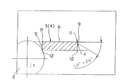
保持器3,4における柱部6のエッジの面取り部9は、その断面形状が傾斜した直線状となるものであっても、また凸曲線状となるものであっても良い。傾斜した直線状の面取り部9とする場合、面取り部9の保持器表面に対する傾斜角度を10°〜30°とするのが望ましい。
また、凸曲線状の断面形状の面取り部9とする場合は、面取り部9と保持器表面との繋ぎ部を滑らかな形状とするのが望ましい。上記凸曲線は、円弧状の曲線であっても、また次第に曲率が変わるような曲線であっても良い。
【0019】
なお、上記実施形態では、保持器3,4のポケット5を単純な矩形としたが、他の実施形態として、図5(A)や同図(B)にそれぞれ示すように、ポケット5の長手方向に沿う内側面の両端部または中間部に、盗み溝5a,5bを設けても良い。盗み溝5a,5bは、保持器3,4の内外両面に貫通している。
このように、ポケット5に盗み溝5a,5bを設けた場合、保持器3,4の内側への油流入が多くなり、潤滑性がさらに向上する。また、図5(A)のようにポケット5の両端部に盗み溝5aを設けた場合は、図6(A)のように面取り部9が施されるエッジが、ポケット5の隅部から分断されたポケット内突出部となる。そのため、この部分への潰し加工を容易に行うことができる。図6において、ハッチング部分は面取り部9を示す。ちなみに、このような盗み溝5aを設けない場合は、図6(B)のように面取り部9がされる柱部6のエッジが、ポケット5の隅部から分断されないので、この部分への潰し加工を行うことが難しい。
【0020】
なお、上記実施形態では、針状ころ2が単列の場合を例示して説明したが、この発明は複列の場合でも同様に適用できる。また、上記各実施形態は、面取り部9を潰し加工部分とする場合につき説明したが、この面取り部9は、他の適宜の加工方法、例えばバレル加工等で施すようにしても良い。
【0021】
【発明の効果】
この発明のスラストころ軸受は、複数の針状ころと、金属板の打ち抜き加工品からなる2枚の略平行な環状の保持器とを備え、これら2枚の保持器のそれぞれが円周方向の複数箇所にポケットを有し、上記各針状ころが上記2枚の保持器の対応するポケットに渡って入れられ、かつこれら2枚の保持器により、各針状ころの保持器軸方向の両側への抜け出しが阻止されたスラストころ軸受において、上記保持器の各ポケット間の柱部のエッジに面取り部を設けたものであるため、ころの周面やスラスト軌道輪の軌道面に形成された油膜の状態を良好に保つことができ、潤滑性を向上させることができる。特に、上記面取り部を潰し加工部分とした場合は、簡単な加工で面取り部の形成が確実に行える。
ポケットの長手方向に沿う内側面に盗み溝を設けた場合は、保持器内への油の流入性が向上し、また面取り部を潰し加工部分とする場合にその潰し加工が簡単かつ良好に行える。
この発明のスラストころ軸受の製造方法は、保持器の各ポケットの柱部のエッジに対面する複数の潰し型部を有するポンチを用い、上記外形およびポケットの打ち抜き状態の保持器に、上記各面取り部を同時に潰し加工する方法であるため、上記面取り部を生産性良く、かつ確実に加工することができる。
【図面の簡単な説明】
【図1】この発明の第1の実施形態にかかるスラストころ軸受を一部省略して示す断面図である。
【図2】(A)は同スラストころ軸受の部分平面図、(B)は同スラスト軸受を保持器円周方向に断面した拡大断面図である。
【図3】同スラストころ軸受の保持器への潰し加工の説明図である。
【図4】同スラストころ軸受の保持器における柱部エッジに潰し加工等で得られる寸法の説明図である。
【図5】他の実施形態における保持器ポケットの形状を示す平面図である。
【図6】(A)は盗み溝付きポケットの場合の面取り部の説明図、(B)はポケットに盗み溝のないポケットの場合の面取り部の説明図である。
【図7】(A)は従来例の平面図、(B)はその保持器円周方向に断面した拡大断面図である。
【符号の説明】
1…スラストころ軸受
2…針状ころ
3,4…保持器
5…ポケット
6…柱部
9…面取り部[0001]
TECHNICAL FIELD OF THE INVENTION
The present invention relates to a thrust roller bearing using a needle roller as a rolling element.
[0002]
[Prior art]
Conventionally, as a thrust roller bearing, a
This type of thrust roller bearing is configured such that each of the
[0003]
[Patent Document 1]
JP-A-2002-250347
[Problems to be solved by the invention]
However, in the conventional thrust roller bearing, when the raceway is guided, the oil film formed on the raceway surface of the thrust raceway is scraped off by the
Conventionally, chemical polishing or the like has been performed to remove the
[0005]
An object of the present invention is to provide a thrust roller bearing capable of maintaining a favorable state of an oil film formed on a peripheral surface of a roller and a raceway surface of a thrust race.
[0006]
[Means for Solving the Problems]
The thrust roller bearing of the present invention includes a plurality of needle rollers and two substantially parallel annular cages formed by stamping a metal plate, and each of the two cages has a circumferential direction. It has pockets at a plurality of locations, and each of the needle rollers is inserted into a corresponding pocket of the two cages, and the two cages are used to hold both needle rollers in the axial direction of the cage. In the thrust roller bearing in which escape to the thrust roller is prevented, a chamfered portion is provided at an edge of a pillar portion between pockets of the retainer.
According to this configuration, since the chamfered portion is provided at the edge of each pillar portion of the cage, burrs at the edge of the pillar portion generated by punching of the pocket can be completely removed, and formed on the raceway surface of the thrust bearing ring. The oil film to be removed is prevented from being scraped off by the burr of the retainer column. Therefore, the oil film on the raceway surface of the thrust race is prevented from being cut, and the original life of the bearing can be exhibited. That is, the oil film forming ability on the raceway surface of the thrust race is kept constant, and the lubricity can be improved.
[0007]
The cross-sectional shape of the chamfer may be an inclined straight line or a convex curve. When the cross-sectional shape of the chamfered portion is an inclined straight line, processing of the chamfered portion is easy, and the shape of the die surface of the punch is simplified when formed with a punch or the like. When the cross-sectional shape of the chamfer is a convex curve, scraping of the oil film formed on the raceway surface is more reliably prevented.
[0008]
The chamfered portion may be a crushed portion by a press. The crushed portion is a portion in which a corner is crushed into a slope or a curved surface by pressing a mold surface of a punch, for example. The crushing process referred to here is also referred to as surface pressing.
When the chamfered portion is a crushed portion, a chamfered portion having a predetermined shape can be reliably formed by simple processing.
[0009]
In the present invention, the chamfered portion may be provided only on the edge of the surface of the cage on the burr generation side during punching of the pocket of the cage. The problem of oil film scraping hardly occurs on the retainer surface on the side where the pull-out occurs during the punching process, even if the chamfered portion is not provided. Therefore, by forming the chamfered portion on only one side, the increase in the number of manufacturing steps can be reduced, and the cost can be suppressed. The surface on the pull-out side may be the side facing the thrust race of the cage or the side facing the non-thrust race.
[0010]
In the present invention, a stealing groove penetrating both sides of the retainer may be provided on the inner surface along the longitudinal direction of the pocket. When the stealing groove is provided in this manner, the flow of oil into the retainer increases, and the lubricity is further improved. Further, when the chamfered portion is a crushed portion, the crushing can be easily performed. In particular, in the case where the stealing grooves are provided at both ends in the longitudinal direction on the inner surface of the pocket, both ends of the mold surface for crushing the punch do not hit the end surface of the inner surface of the pocket, and are located at the formation positions of the stealing grooves. Therefore, crushing can be performed more easily and neatly.
[0011]
Further, in any of these inventions, the two cages may be connected to each other at one or both of the inner peripheral portion and the outer peripheral portion. In the case where the two cages are connected in this manner, the positional deviation between the two cages in the circumferential direction or the axial direction is eliminated, and the trouble due to the positional deviation is avoided.
[0012]
The method for manufacturing a thrust roller bearing according to the present invention is a method for manufacturing the thrust roller bearing having the above-described structure according to the present invention, and in particular, a method for manufacturing the retainer. In this manufacturing method, the cage is formed by punching each pocket from a metal plate, and punching the outer shape and the pocket by using a punch having a plurality of crushed portions facing the edges of the pillars of each pocket. The above-mentioned chamfered portions are simultaneously formed on the cage in the state by crushing.
As described above, by using a punch having a plurality of crushed portions facing the edge of each pillar portion, the chamfered portions can be crushed and processed in each of the plurality of pockets at the same time, and excellent productivity can be obtained. Unlike the radial bearing, the cage in the thrust roller bearing has flat portions formed with the respective column portions, so that simultaneous crushing of such a plurality of column portions can be easily performed. In the case where the stealing groove is formed on the inner surface of the pocket of the retainer, the groove is formed at the same time when the pocket is punched.
[0013]
BEST MODE FOR CARRYING OUT THE INVENTION
A first embodiment of the present invention will be described with reference to FIGS. FIG. 1 is a sectional view showing a thrust roller bearing of this embodiment with a part thereof omitted. The thrust roller bearing 1 includes a plurality of
[0014]
As shown in FIG. 2A, each of the two
[0015]
The
Here, the
[0016]
The processing of the chamfered
[0017]
According to the thrust roller bearing 1 of this configuration, the chamfered
[0018]
The chamfered
When the chamfered
[0019]
In the above embodiment, the
As described above, when the stealing
[0020]
In the above embodiment, the case where the
[0021]
【The invention's effect】
The thrust roller bearing of the present invention includes a plurality of needle rollers and two substantially parallel annular cages formed by stamping a metal plate, and each of the two cages has a circumferential direction. It has pockets at a plurality of locations, and each of the needle rollers is inserted into a corresponding pocket of the two cages, and the two cages are used to hold both needle rollers in the axial direction of the cage. In the thrust roller bearing in which escape to the thrust roller is prevented, since the chamfered portion is provided at the edge of the column between the pockets of the retainer, the thrust roller bearing is formed on the peripheral surface of the roller and the raceway surface of the thrust race. The state of the oil film can be kept good, and the lubricity can be improved. In particular, when the chamfered portion is a crushed processed portion, the chamfered portion can be reliably formed by simple processing.
When a stealing groove is provided on the inner side surface along the longitudinal direction of the pocket, the inflow of oil into the cage is improved, and when the chamfered portion is formed as a crushed portion, the crushing can be performed easily and favorably. .
The method for manufacturing a thrust roller bearing according to the present invention uses a punch having a plurality of crushed portions facing the edges of the pillars of each pocket of the cage, and the above-described chamfering is performed on the cage in the punched state of the outer shape and the pocket. Since this is a method of simultaneously crushing and processing the chamfered portion, the chamfered portion can be processed with good productivity and reliably.
[Brief description of the drawings]
FIG. 1 is a cross-sectional view partially showing a thrust roller bearing according to a first embodiment of the present invention;
FIG. 2A is a partial plan view of the thrust roller bearing, and FIG. 2B is an enlarged cross-sectional view of the thrust roller bearing in a retainer circumferential direction.
FIG. 3 is an explanatory view of crushing the thrust roller bearing into a cage.
FIG. 4 is an explanatory view of dimensions obtained by crushing a column edge in a cage of the thrust roller bearing.
FIG. 5 is a plan view showing the shape of a retainer pocket according to another embodiment.
FIG. 6A is an explanatory diagram of a chamfered portion in the case of a pocket having a stealing groove, and FIG. 6B is an explanatory diagram of a chamfered portion in the case of a pocket having no stealing groove in the pocket.
FIG. 7A is a plan view of a conventional example, and FIG. 7B is an enlarged cross-sectional view of the retainer in a circumferential direction.
[Explanation of symbols]
DESCRIPTION OF SYMBOLS 1 ...
Claims (7)
Priority Applications (1)
| Application Number | Priority Date | Filing Date | Title |
|---|---|---|---|
| JP2003000860A JP2004211835A (en) | 2003-01-07 | 2003-01-07 | Thrust roller bearing |
Applications Claiming Priority (1)
| Application Number | Priority Date | Filing Date | Title |
|---|---|---|---|
| JP2003000860A JP2004211835A (en) | 2003-01-07 | 2003-01-07 | Thrust roller bearing |
Publications (2)
| Publication Number | Publication Date |
|---|---|
| JP2004211835A true JP2004211835A (en) | 2004-07-29 |
| JP2004211835A5 JP2004211835A5 (en) | 2006-01-26 |
Family
ID=32819029
Family Applications (1)
| Application Number | Title | Priority Date | Filing Date |
|---|---|---|---|
| JP2003000860A Pending JP2004211835A (en) | 2003-01-07 | 2003-01-07 | Thrust roller bearing |
Country Status (1)
| Country | Link |
|---|---|
| JP (1) | JP2004211835A (en) |
Cited By (2)
| Publication number | Priority date | Publication date | Assignee | Title |
|---|---|---|---|---|
| JP2007085529A (en) * | 2005-09-26 | 2007-04-05 | Tsubakimoto Chain Co | Silent chain |
| EP1657460A3 (en) * | 2004-11-16 | 2008-07-02 | JTEKT Corporation | Roller thrust bearing cage and manufacturing method thereof |
-
2003
- 2003-01-07 JP JP2003000860A patent/JP2004211835A/en active Pending
Cited By (4)
| Publication number | Priority date | Publication date | Assignee | Title |
|---|---|---|---|---|
| EP1657460A3 (en) * | 2004-11-16 | 2008-07-02 | JTEKT Corporation | Roller thrust bearing cage and manufacturing method thereof |
| US7837394B2 (en) | 2004-11-16 | 2010-11-23 | Jtekt Corporation | Roller thrust bearing cage and manufacturing method thereof |
| US8627570B2 (en) | 2004-11-16 | 2014-01-14 | Jtekt Corporation | Roller thrust bearing cage and manufacturing method thereof |
| JP2007085529A (en) * | 2005-09-26 | 2007-04-05 | Tsubakimoto Chain Co | Silent chain |
Similar Documents
| Publication | Publication Date | Title |
|---|---|---|
| WO2012137788A1 (en) | Thrust bearing holder and thrust bearing | |
| US20110116734A1 (en) | Punched retainer, self-aligning roller bearing, and method of manufacturing punched retainer | |
| JP2006144839A (en) | Roller bearing | |
| CN107110220B (en) | Retainer for thrust roller bearing and method for manufacturing the same | |
| JP4517759B2 (en) | Method for manufacturing roller bearing cage | |
| WO2014058038A1 (en) | Bearing device | |
| JP2009287785A (en) | Roller bearing retainer | |
| JP2006112584A (en) | Roller bearing cage | |
| JP2007255563A (en) | Dual row roller bearing | |
| JP2004211835A (en) | Thrust roller bearing | |
| JP4483803B2 (en) | Thrust cylindrical roller bearing | |
| JP2008202759A (en) | Thrust roller bearing | |
| JP7147257B2 (en) | thrust roller bearing | |
| JP2006017244A (en) | Thrust roller bearing | |
| JP2005195143A (en) | Needle roller bearing | |
| JP2003049844A (en) | Thrust roller bearing | |
| JP2010025230A (en) | Pressed cage, self-aligning roller bearing, and manufacturing method for pressed cage | |
| JP2009162360A (en) | Thrust roller bearing and its retainer | |
| JPH06117440A (en) | Retainer for roller bearing | |
| JP6750331B2 (en) | Method for manufacturing cage for thrust roller bearing | |
| JP7212738B1 (en) | ball bearing | |
| JP2002115723A (en) | Roller bearing retainer | |
| JP2010053886A (en) | Retainer for thrust roller bearing | |
| JP2007170562A (en) | Shell type roller bearing for laminated connecting rod and connecting rod assembly | |
| WO2023286527A1 (en) | Roller bearing retainer and roller bearing |
Legal Events
| Date | Code | Title | Description |
|---|---|---|---|
| A521 | Written amendment |
Free format text: JAPANESE INTERMEDIATE CODE: A523 Effective date: 20051201 |
|
| A621 | Written request for application examination |
Free format text: JAPANESE INTERMEDIATE CODE: A621 Effective date: 20051201 |
|
| A977 | Report on retrieval |
Free format text: JAPANESE INTERMEDIATE CODE: A971007 Effective date: 20080507 |
|
| A131 | Notification of reasons for refusal |
Free format text: JAPANESE INTERMEDIATE CODE: A131 Effective date: 20080520 |
|
| A521 | Written amendment |
Free format text: JAPANESE INTERMEDIATE CODE: A523 Effective date: 20080716 |
|
| A521 | Written amendment |
Free format text: JAPANESE INTERMEDIATE CODE: A523 Effective date: 20080717 |
|
| A131 | Notification of reasons for refusal |
Free format text: JAPANESE INTERMEDIATE CODE: A131 Effective date: 20080930 |
|
| A521 | Written amendment |
Free format text: JAPANESE INTERMEDIATE CODE: A523 Effective date: 20081126 |
|
| A02 | Decision of refusal |
Free format text: JAPANESE INTERMEDIATE CODE: A02 Effective date: 20090106 |