JP2004208687A - Device for overlapping sheet shaped pieces - Google Patents
Device for overlapping sheet shaped pieces Download PDFInfo
- Publication number
- JP2004208687A JP2004208687A JP2003319235A JP2003319235A JP2004208687A JP 2004208687 A JP2004208687 A JP 2004208687A JP 2003319235 A JP2003319235 A JP 2003319235A JP 2003319235 A JP2003319235 A JP 2003319235A JP 2004208687 A JP2004208687 A JP 2004208687A
- Authority
- JP
- Japan
- Prior art keywords
- sheet
- bread
- transport line
- piece
- transport
- Prior art date
- Legal status (The legal status is an assumption and is not a legal conclusion. Google has not performed a legal analysis and makes no representation as to the accuracy of the status listed.)
- Granted
Links
- 238000001514 detection method Methods 0.000 claims abstract description 10
- 238000003825 pressing Methods 0.000 claims description 40
- 230000007246 mechanism Effects 0.000 claims description 33
- 235000008429 bread Nutrition 0.000 abstract description 262
- 230000008878 coupling Effects 0.000 abstract 1
- 238000010168 coupling process Methods 0.000 abstract 1
- 238000005859 coupling reaction Methods 0.000 abstract 1
- 230000032258 transport Effects 0.000 description 171
- 238000004080 punching Methods 0.000 description 94
- 235000009508 confectionery Nutrition 0.000 description 75
- 210000005069 ears Anatomy 0.000 description 37
- 239000013067 intermediate product Substances 0.000 description 29
- 238000011144 upstream manufacturing Methods 0.000 description 28
- 238000004519 manufacturing process Methods 0.000 description 24
- 235000013305 food Nutrition 0.000 description 22
- 238000005520 cutting process Methods 0.000 description 20
- 230000002093 peripheral effect Effects 0.000 description 11
- 230000008859 change Effects 0.000 description 6
- 238000002788 crimping Methods 0.000 description 4
- 238000005192 partition Methods 0.000 description 4
- 230000000694 effects Effects 0.000 description 3
- 238000000034 method Methods 0.000 description 3
- 230000004048 modification Effects 0.000 description 3
- 238000012986 modification Methods 0.000 description 3
- 230000008569 process Effects 0.000 description 3
- 230000009471 action Effects 0.000 description 2
- 239000006071 cream Substances 0.000 description 2
- 238000007654 immersion Methods 0.000 description 2
- 230000002452 interceptive effect Effects 0.000 description 2
- 235000016790 Allium chinense Nutrition 0.000 description 1
- 244000295724 Allium chinense Species 0.000 description 1
- 238000005452 bending Methods 0.000 description 1
- 238000006243 chemical reaction Methods 0.000 description 1
- 230000006835 compression Effects 0.000 description 1
- 238000007906 compression Methods 0.000 description 1
- 238000010586 diagram Methods 0.000 description 1
- 238000006073 displacement reaction Methods 0.000 description 1
- 230000005484 gravity Effects 0.000 description 1
- 238000000465 moulding Methods 0.000 description 1
- 239000000047 product Substances 0.000 description 1
- 230000004044 response Effects 0.000 description 1
- 230000002441 reversible effect Effects 0.000 description 1
- 230000000630 rising effect Effects 0.000 description 1
- 239000007787 solid Substances 0.000 description 1
- 238000007711 solidification Methods 0.000 description 1
- 230000008023 solidification Effects 0.000 description 1
- 230000001360 synchronised effect Effects 0.000 description 1
Images


Abstract
Description
本発明は、2枚のシート状片の重ね置き装置に係り、特に、搬送される1枚毎のシート状片に他の1枚のシート状片を重ね置きさせるシート状片の重ね置き装置に関する。 The present invention relates to an apparatus for stacking two sheet-shaped pieces, and more particularly, to an apparatus for stacking sheet-shaped pieces for stacking another sheet-shaped piece on each conveyed sheet-shaped piece. .
例えば、シート状片がシート状食パン片であるとして、例えば、2枚のシート状食パン片の間にフィリングを存在させた菓子パンは既に製造されているもので、その製造については例えば特許文献1に開示されており、その概要は次のとおりである。 For example, assuming that the sheet-shaped piece is a sheet-shaped bread piece, for example, a confectionery bread in which a filling is present between two sheet-shaped bread pieces has already been manufactured. It is disclosed and its summary is as follows.
図21及び図22に示すように、従来は、耳付シート状食パンWは肉厚となしたものを使用し、その肉厚な厚さ方向中間箇所へ適当長さに切り込みを入れ、片端を付着させたままの状態の上側食パン部分をその切り込み側から持ち上げて下側食パン部分との間にフィリングを供給することにより菓子パン中間品Waを形成するのであり、次に、図22に示すように、この菓子パン中間品Waは食品用抜き型装置S上に移動させ、ここで一対の抜き型Sa,Saのそれぞれを特定軸回りへ回転させながら挟み付け、且つ抜き型Sa,Saを作動させて外周部分Wbと切り離すように行っている。 As shown in FIG. 21 and FIG. 22, conventionally, a thick bread sheet W with ears is used, and a cut is made to an appropriate length in a middle portion in the thickness direction of the thick bread bread, and one end is cut. The confectionery bread intermediate Wa is formed by lifting the upper bread portion in the attached state from the cut side and supplying a filling between the upper bread portion and the lower bread portion, and then, as shown in FIG. Then, the confectionery bread intermediate product Wa is moved onto the food cutting die apparatus S, where the pair of cutting dies Sa, Sa are pinched while rotating each around a specific axis, and the cutting dies Sa, Sa are operated. It is performed so as to be separated from the outer peripheral portion Wb.
上記した従来の菓子パンの製造方法では、前記の通り肉厚パンWを使用しその切り込みで形成された上側食パン部分と前記下側食パン部分との間へ、フィリングを差し込み状態に供給するようになすのであり、従って該フィリングの供給に際して上側の食パンを一時的に持ち上げることが必要となって手間取る上に、フィリングの量を余り多くできない、フィリングを幅広の板状に供給し、特に複数層の積層状態に載置することや、固形フィリングの供給が困難であるなどの不都合があった。また、前記菓子パンの上側食パン部分と下側食パン部分とで食パンの種類を異にすることができない。
本発明はこれらの不都合に対処せんとするものであり、その課題は、搬送される1枚毎のシート状片に他の1枚のシート状片を重ね置きさせ、しかも、2枚のシート状片同士を確実に合わせることができるようにするシート状片の重ね置き装置を提供することを目的とする。
In the above-described conventional confectionery bread manufacturing method, the filling is supplied in an inserted state between the upper bread portion and the lower bread portion formed by cutting the thick bread W as described above. Therefore, it is necessary to temporarily lift the upper bread when supplying the filling, and it takes time and effort, and the amount of the filling cannot be increased so much. There are inconveniences, such as mounting in a state and difficulty in supplying a solid filling. Further, the type of bread cannot be different between the upper bread portion and the lower bread portion of the confectionery bread.
The present invention is intended to address these inconveniences, and has as its object the problem that one sheet-like piece to be conveyed is superimposed on another sheet-like piece. It is an object of the present invention to provide an apparatus for stacking sheet-like pieces so that the pieces can be surely fitted together.
上記目的を達成するため、本発明は、第一搬送ラインと第二搬送ラインを形成して、それぞれの搬送ラインで1枚ずつのシート状片を搬送させ、前記第二搬送ラインにより搬送された1枚のシート状片を前記第一搬送ラインの搬送途中で該第一搬送ラインで搬送される1枚毎のシート状片に重ね置きさせるシート状片の重ね置き装置において、
前記第二搬送ラインの先端側を、該第二搬送ラインのシート状片の搬送方向が上から見て前記第一搬送ラインのシート状片の搬送方向と同一になり、かつ横から見て前記第一搬送ラインのシート状片の搬送方向に対して下り傾斜になるように、前記第一搬送ラインの途中箇所の特定高さ位置に配置し、前記第一搬送ラインに設けられ、該第一搬送ラインのシート状片が前記第二搬送ラインの先端位置に対して所定位置に来たことを検知するセンサと、前記第二搬送ラインに設けられ、その先端に至ったシート状片を停止させるとともに前記センサの検知に基づいて所定のタイミングで停止解除して該第二搬送ラインからのシート状片の先端を前記第一搬送ラインで搬送されるシート状片の先端に合致させて重ね合わせるようにする上ストッパとを備えて構成した。
In order to achieve the above object, the present invention forms a first transport line and a second transport line, transports one sheet-like piece by each transport line, and is transported by the second transport line. A sheet-like piece stacking device for stacking one sheet-like piece on each sheet-like piece conveyed on the first conveyance line during conveyance on the first conveyance line,
The tip side of the second transport line, the transport direction of the sheet-like pieces of the second transport line is the same as the transport direction of the sheet-like pieces of the first transport line when viewed from above, and when viewed from the side, The first transport line is disposed at a specific height position in the middle of the first transport line so as to be inclined downward with respect to the transport direction of the sheet-like piece of the first transport line, and is provided on the first transport line. A sensor for detecting that the sheet-like piece of the transport line has come to a predetermined position with respect to the leading end position of the second transport line; and a sensor provided on the second transport line to stop the sheet-like piece reaching the leading end. At the same time, the stop is released at a predetermined timing based on the detection of the sensor, and the leading end of the sheet-like piece from the second transport line is aligned with the leading end of the sheet-like piece transported on the first transport line so as to be overlapped. On the stopper It was configured with.
上記目的を達成するため、本発明のシート状片の重ね置き装置では、先ず、第一搬送ラインと第二搬送ラインを形成して、それぞれの搬送ラインで1枚ずつのシート状片を搬送させ、前記第二搬送ラインにより搬送された1枚のシート状片を前記第一搬送ラインの搬送途中で該第一搬送ラインで搬送される1枚毎のシート状片に重ね置きさせる。
そのため、例えば、2枚のシート状食パン片の間にフィリングを存在させた菓子パンにおいて、片端が付着したまま上下配置された状態の耳付シート状食パン部分の上側の耳付シート状食パン片を切り込み側から持ち上げてフィリングの供給のために開口させるという従来の処理は不要となり、従ってフィリングを供給される前記耳付シート状食パン片の搬送速度は、上下配置された状態の耳付シート状食パン部分(耳付シート状食パン片)を離間させる従来の処理よりも増大されるものとなり、またフィリングの供給スペースが従来に較べて広く確保されてフィリングの供給量の増大化・板状化・積層化や固形化が図れるものとなる。加えて、上下の耳付シート状食パン片の種類や肉厚寸法は自由な選定が可能であり、このことは重ね合わせの両者間でもその種類や全体肉厚寸法を簡便且つ自由に変更可能となし、上記フィリングの多様化と共に食感的にも色々なバラエティを持たせることができるものとなる。
さらに、本発明によれば、前記第一搬送ラインに設けられたセンサの検知に基づいて所定のタイミングで前記第二搬送ラインに設けられた上ストッパを停止解除して第二搬送ラインからの上側のシート状片を降下させて第一搬送ラインで搬送される下側のシート状片に重ね合わせるようにするので、上側のシート状片の降下の際、下側のシート状片とのタイミングを調整でき、そのため、上下のシート状片の先端同士を確実に合わせることができるようになる。
In order to achieve the above object, in the sheet-like piece stacking apparatus of the present invention, first, a first transport line and a second transport line are formed, and one sheet-like piece is transported on each transport line. One sheet-like piece transported by the second transport line is superimposed on each sheet-like piece transported by the first transport line during the transport of the first transport line.
Therefore, for example, in a confectionery bread in which a filling is present between two sheet-like bread pieces, the upper side of the sheet-like bread piece with the ear is vertically cut with one end attached, and the upper side of the sheet-like bread piece with the ear is cut. The conventional processing of lifting from the side and opening it for supplying the filling becomes unnecessary, and therefore, the conveying speed of the sheet-like bread with ears to which the filling is supplied is limited to the sheet-like bread with ears arranged vertically. (Sheet bread pieces with ears) will be increased compared to the conventional treatment, and the filling supply space will be wider than before so that the amount of filling to be supplied can be increased, plate-shaped and laminated. And solidification can be achieved. In addition, the type and thickness of the upper and lower eared sheet-shaped bread pieces can be freely selected, which means that the type and the overall thickness can be easily and freely changed between the two layers. None, with the diversification of the above-mentioned fillings, various textures can be provided.
Further, according to the present invention, the upper stopper provided on the second transport line is stopped and released at a predetermined timing based on the detection of the sensor provided on the first transport line, and the upper stopper from the second transport line is released. The lower sheet-shaped piece is lowered so as to overlap the lower sheet-shaped piece conveyed on the first conveyance line, so that when the upper sheet-shaped piece is lowered, the timing with the lower sheet-shaped piece is adjusted. It can be adjusted, so that the top ends of the upper and lower sheet-like pieces can be surely aligned with each other.
そして、必要に応じ、前記上ストッパを、前記第二搬送ラインの先端よりも前方に設け、該先端と上ストッパとの間に空間を設けたことが有効である。上側のシート状片の先端は、第二搬送ラインの先端と上ストッパとの間の空間に露出して停止させられた状態から降下するので、上側のシート状片の先端位置を下側のシート状片に極めて近い位置に位置させることができ、そのため、降下距離を短くできるので、それだけ、より正確に上下のシート状片の先端同士を合わせることができるようになる。 And it is effective to provide the upper stopper ahead of the tip of the second transport line as needed, and to provide a space between the tip and the upper stopper. Since the leading end of the upper sheet-like piece is exposed to the space between the leading end of the second transport line and the upper stopper and descends from the stopped state, the leading end position of the upper sheet-like piece is changed to the lower sheet. Since it can be located at a position very close to the sheet-like piece, and therefore the descending distance can be shortened, the leading ends of the upper and lower sheet-like pieces can be more accurately aligned.
また、必要に応じ、前記第一搬送ラインに、前記シート状片の重ね合わせの際、前記第二搬送ラインの先端よりも前方で該第一搬送ラインのシート状片の先端に係合して一時的に停止させる下ストッパを設けた構成としている。下側のシート状片が下ストッパによって、停止させられて、上側からのシート状片を待ち受けるようになるので、この点でより正確に上下のシート状片の先端同士を合わせることができるようになる。 Further, if necessary, when the sheet-like pieces are superimposed on the first transport line, the sheet-like pieces are engaged with the leading edge of the sheet-like piece of the first transport line ahead of the leading edge of the second transport line. A lower stopper for temporarily stopping is provided. Since the lower sheet-like piece is stopped by the lower stopper and waits for the sheet-like piece from above, the leading ends of the upper and lower sheet-like pieces can be more accurately aligned at this point. Become.
更に、必要に応じ、前記上ストッパの後方に、シート状片を押える一又は複数の押えローラを設けた構成としている。該上ストッパの停止解除に伴う上昇等の移動やシート状片が降下する際には、シート状片が一又は複数の押えローラによって押えられているので、シート状片の先端が上や下に撓むことがなく、そのため、より確実に下側のシート状片の先端と位置合わせが行なわれる。 Further, if necessary, one or more pressing rollers for pressing the sheet-like piece are provided behind the upper stopper. When the sheet-like piece moves down or lifts due to the release of the stop of the upper stopper, or when the sheet-like piece descends, the sheet-like piece is pressed by one or a plurality of pressing rollers. There is no bending, so that the alignment with the tip of the lower sheet-like piece is performed more reliably.
更にまた、必要に応じ、前記重ね合わされた2枚のシート状片の重ね位置を再度調整する重ね位置調整機構を設けた構成としている。多少上下のシート状片間にずれがあっても、これが修正され、上下のシート状片が確実に合致するようになる。 Furthermore, if necessary, a superposition position adjusting mechanism for adjusting the superposition position of the two superposed sheets is again provided. Any deviation between the upper and lower sheet-like pieces is corrected, and the upper and lower sheet-like pieces are surely matched.
この場合、前記重ね位置調整機構を、前記第一搬送ラインの重ね合わされたシート状片の移動径路にその下側から進出し該シート状片を前後から挾持する複数のフィンガと、該フィンガを前記移動径路に進出させて所定時間維持した後に退出させるフィンガ進退動部と、前記移動径路に進出したフィンガの全部又は一部を前後方向に移動させてシート状片を挾持するとともに挾持後に後退させるフィンガ挾持駆動部とを備えて構成したことが有効である。フィンガで挾持して調整するので、機構が容易になる。
また、上記フィンガを、シート状片の4つのコーナを押えるように断面略L字状に形成するとともに前後に一対ずつ設けたことが有効である。フィンガは、シート状片の4つのコーナ部を押えるので、左右前後の押さえが確実になり、上下のシート状片がより一層確実に合致するようになる。
なお、本明細書において、前方とは搬送方向の下流と同じ意味であり、又後方とは上流と同じ意味である。
In this case, the stacking position adjusting mechanism includes a plurality of fingers which advance from the lower side of the moving path of the superposed sheet-like pieces of the first transport line and hold the sheet-like pieces from front and rear, and A finger advancing / retracting portion for advancing to the moving path and maintaining the same for a predetermined time and then retreating; and a finger for moving all or a part of the finger advancing to the moving path in the front-rear direction to clamp the sheet-like piece and retract after the clamping. It is effective to provide a holding drive unit. Since the adjustment is performed by holding the finger, the mechanism is simplified.
Further, it is effective that the fingers are formed to have a substantially L-shaped cross section so as to press the four corners of the sheet-like piece, and a pair of the fingers is provided in front and rear. Since the finger presses the four corner portions of the sheet-like piece, the left-right and front-rear pressing is ensured, and the upper and lower sheet-like pieces are more reliably matched.
In this specification, “forward” has the same meaning as “downstream” in the transport direction, and “backward” has the same meaning as “upstream”.
本発明のシート状片の重ね置き装置によれば、先ず、第一搬送ラインと第二搬送ラインを形成して、それぞれの搬送ラインで1枚ずつのシート状片を搬送させ、前記第二搬送ラインにより搬送された1枚のシート状片を前記第一搬送ラインの搬送途中で該第一搬送ラインで搬送される1枚毎のシート状片に重ね置きさせるので、例えば、該シート状片がシート状食パン片であるとして、2枚のシート状食パン片の間にフィリングを存在させた菓子パンにおいて、片端が付着したまま上下配置された状態の耳付シート状食パン部分の上側の耳付シート状食パン片を切り込み側から持ち上げてフィリングの供給のために開口させるという従来の処理は不要となり、従ってフィリングを供給される前記耳付シート状食パン片の搬送速度は、上下配置された状態の耳付シート状食パン部分(耳付シート状食パン片)を離間させる従来の処理よりも増大し、フィリングを幅広の板状に供給して特に複数層の積層状態に載置させることができ、また、フィリングの供給スペースが従来に較べて広く確保されてフィリングの供給量の増大化や固形化を図ることができるようになる。加えて、上下の耳付シート状食パン片の種類や肉厚寸法は自由な選定が可能であり、このことは重ね合わせの両者間でもその種類や全体肉厚寸法を簡便且つ自由に変更可能となし、上記フィリングの多様化と共に食感的にも色々なバラエティを持たせることができるものとなる。 According to the sheet-like piece stacking device of the present invention, first, a first transport line and a second transport line are formed, and one sheet-like piece is transported on each transport line. Since one sheet-like piece conveyed by the line is superimposed on each sheet-like piece conveyed by the first conveyance line during the conveyance of the first conveyance line, for example, the sheet-like piece is In a confectionery bread in which a filling is present between two sheet-shaped bread pieces assuming a sheet-shaped bread piece, an ear-shaped sheet-shaped bread part having an ear and being arranged vertically with one end attached. The conventional process of lifting the bread pieces from the cut side and opening them for supplying the filling becomes unnecessary. Therefore, the conveying speed of the sheet-like bread pieces with ears to which the filling is supplied is vertically arranged. To increase the filling compared to the conventional processing of separating the sheet-like bread slices with ears (sheet-like bread slices with ears), to supply the filling in a wide plate shape, and to place the filling in a multi-layered state. In addition, the space for supplying the filling is widely secured as compared with the related art, so that the supply amount of the filling can be increased and the filling can be solidified. In addition, the type and thickness of the upper and lower eared sheet-shaped bread pieces can be freely selected, which means that the type and the overall thickness can be easily and freely changed between the two layers. None, with the diversification of the above-mentioned fillings, various textures can be provided.
また、第一搬送ラインに設けられたセンサの検知に基づいて所定のタイミングで第二搬送ラインに設けられた上ストッパを停止解除して第二搬送ラインからの上側のシート状片を降下させて第一搬送ラインで搬送される下側のシート状片に重ね合わせるようにするので、上側のシート状片の降下の際、下側のシート状片とのタイミングを調整でき、そのため、上下のシート状片の先端同士を確実に合わせることができるようになるなどの効果を奏する。 Further, at a predetermined timing based on the detection of the sensor provided on the first transport line, the upper stopper provided on the second transport line is stopped and released to lower the upper sheet-like piece from the second transport line. Since it is made to overlap with the lower sheet-shaped piece conveyed in the first conveyance line, when the upper sheet-shaped piece descends, the timing with the lower sheet-shaped piece can be adjusted. This has the effect that the tips of the pieces can be surely aligned with each other.
以下、添付図面に基づいて、本発明の実施の形態に係るシート状片の重ね置き装置について詳細に説明する。本発明の実施の形態に係るシート状片の重ね置き装置は、例えば菓子パンの製造装置に用いられるので、ここでは菓子パンの製造装置の説明で説明する。なお、本実施の形態は、本発明の最適実施態様の一つを示すものであり、これに本発明の範囲を限る趣旨ではない。 Hereinafter, an apparatus for stacking sheet-like pieces according to an embodiment of the present invention will be described in detail with reference to the accompanying drawings. Since the apparatus for stacking sheet-like pieces according to the embodiment of the present invention is used, for example, in a confectionery bread manufacturing apparatus, the explanation will be made here on the confectionery bread manufacturing apparatus. The present embodiment shows one of the most suitable embodiments of the present invention, and does not limit the scope of the present invention.
本発明の実施の形態に係るシート状片の重ね置き装置が用いられる菓子パンの製造装置においては、図1に示す通り、第一搬送ライン、第二搬送ライン及び食パン重ね置き装置が二列並んで設けられており、これに対応して一つの食品用抜き型装置に於いて、受渡し搬送部及び搬送手段が二列並んで設けられている例について述べる。 In the confectionery bread manufacturing apparatus in which the sheet-like piece stacking device according to the embodiment of the present invention is used, as shown in FIG. 1, the first transfer line, the second transfer line, and the bread stacking device are arranged in two rows. In this case, a description will be given of an example in which the delivery / conveyance section and the conveyance means are provided in two rows in one food punching apparatus.
図1において、1A及び1Bは何れも食パンスライス送出装置で、3斤分の棒状食パンwを供給してこの食パンwを例えば8mm〜15mm程度の厚さの耳付シート状食パン片w1にスライスするスライサ2と、このようにスライスされた耳付シート状食パン片w1を1枚ずつ連続的に送り出す送出機構3とを備えたものとなされている。
In FIG. 1, each of 1A and 1B is a bread slice sending device, which supplies three loaves of stick-like bread w and slices the bread w into sheet-like bread pieces w1 with ears having a thickness of, for example, about 8 mm to 15 mm. A
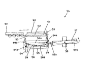
そして、図1及び図2に示すように、2つの食パンスライス送出装置1A、1Aのそれぞれから第一搬送ライン4a、4bが前方へ直線状且つ水平状に延出されており、また他の2つの食パンスライス送出装置1B、1Bのそれぞれから第二搬送ライン5a、5bが前方へ向けて直線状且つ上り傾斜状に延出され第一搬送ライン4a、4bよりも数十cm程度高い位置に導かれた後に水平状に延出されてからそれぞれ第一搬送ライン4a、4bへ向かって直角に折れて横方へ水平状に導かれ、それぞれ第一搬送ライン4a、4bの上方まで延出される。その後、一方の第二搬送ライン5aは第一搬送ライン4a上方で直角に前方へ向けて折れてから直線状且つ下り傾斜状に延出してその先端を第一搬送ライン4aの途中箇所上方の特定高さ位置に配置させ、また他方の第二搬送ライン5bも同様に第一搬送ライン4b上方で直角に前方向へ折れてから直線状且つ下り傾斜状に延出してその先端を第一搬送ライン4bの途中箇所上方の特定高さ位置に配置されるようになっている。 As shown in FIGS. 1 and 2, the first transport lines 4a and 4b extend linearly and horizontally forward from each of the two bread slice delivery devices 1A and 1A. The second transport lines 5a and 5b extend straight forward and incline from each of the two bread slice delivery devices 1B and 1B, and are guided to a position about several tens cm higher than the first transport lines 4a and 4b. After being extended horizontally, they are bent at right angles toward the first transport lines 4a, 4b, respectively, guided horizontally horizontally, and extended to above the first transport lines 4a, 4b, respectively. Thereafter, one of the second transport lines 5a is bent forward at a right angle above the first transport line 4a, and then extends linearly and downwardly in an inclined manner, and its tip is located above the halfway point of the first transport line 4a. Similarly, the other second transport line 5b is similarly bent forward at a right angle above the first transport line 4b, and then extends linearly and downwardly in an inclined manner. It is arranged at a specific height position above the middle of 4b.
この際、第一搬送ライン4a、4bと第二搬送ライン5a、5bとは、具体的には何れも、適当肉厚で単一の耳付シート状食パン片w1を載置して連続又は間歇搬送することができる搬送コンベアである。該搬送コンベアは、第一搬送ラインとしては無端搬送ベルトコンベアか、これにその一部区間にローラーコンベアを組み込んだものが好適である。また第二搬送ラインとしては直線ラインは無端搬送ベルトコンベアか、これにその一部区間にローラーコンベアを組み込んだものが、直角に折れるラインはローラーコンベアが好適である。本発明では、第一搬送ライン及び第二搬送ラインにおいて直角に折れて食パンの搬送方向を直角に変換する直角ラインにおいては、少なくとも直角ラインの方向変換前のラインにローラコンベアを用いていることが望ましいが、本実施の形態では、該方向変換前・後においてはローラコンベアを用いている。 At this time, the first transport lines 4a, 4b and the second transport lines 5a, 5b are each continuously or intermittently loaded with a single bread sheet w1 having an appropriate thickness and having ears. It is a conveyor that can be transported. The transport conveyor is preferably an endless transport belt conveyor as the first transport line, or a roller conveyor incorporated in a partial section thereof. As the second transport line, a straight line is an endless transport belt conveyor, or a roller conveyor is incorporated in a part thereof, and a roller conveyor is suitable for a line that is bent at a right angle. In the present invention, in the right angle line that is bent at right angles in the first transfer line and the second transfer line to change the transfer direction of the bread to a right angle, at least a roller conveyor is used for a line before the direction change of the right angle line. Although desirable, in the present embodiment, a roller conveyor is used before and after the direction change.
そして、この直角ラインには、図1,図3及び図4に示すように、方向変換機構50が設けられている。方向変換機構50は、ローラコンベア51のローラ52間に下側から臨んで進退動し進出時にローラ52の上端から突出して方向変換前のローラコンベア51の進行方向に直交する方向に食パン片w1を押し出すロッド53を備えている。ロッド53はくし歯状に複数設けられ、各ロッド53は保持体54に保持されている。
また、ロッド53の進出時にロッド53をローラ52の上端から突出させて食パン片w1を押し出すと共に押出端側で前記ローラ52の上端より下側に没入させてからロッド53の進出時位置まで没入状態で後退させた後、該進出時位置でロッド53をローラ52の上端から突出させるようにロッド53の軌道を規定するガイドレール55を備えている。ガイドレール55は保持体54の一端部から突出したピン54aをガイドするガイド溝56を有したブロック体で構成されている。
該ガイド溝56は、長手方向に沿って仕切板59で仕切られており、該仕切板59によって仕切られて上側に設けられたロッド53による食パンw1の押出時のピン54aの往動経路56aと、往動経路56aの下側に設けられたロッド53の後退時のピン54aの復動経路56bとを備えている。該往動経路56aは、ロッド53の押出端側で上部が下側に滑らかに傾斜する傾斜部を有しており、ロッド53が押出端側ではローラ52の上端の下側にスムーズに没入することができるようにしている。仕切板59の先端には該往動経路56aの上部に当接する板バネ59aが突設されており、後退時のピン54aが往動経路56aに逆進入するのを防止している。
即ち、ロッド53の押出端側部分における仕切板59の先端を、上側に付勢されている板バネ59aとしたので、押出端側でロッド53がローラ52の下側に没入するときに、突出ピン54aが板バネ59aを押して通過した後に板バネ59aは直ぐにガイド溝56の往動経路56aの上側に付勢されて往動経路56aを閉じるため、ピン54aが往動経路56aに逆進入せずに復動経路56bを通るようになる。この場合、復動経路56bは、往動経路56aの下側に設けられているので、ロッド53の先端がローラコンベア51のローラ52の下に位置した状態で後退させられる。そのため、ロッド53が、その戻り時に、次に搬送されてくる食パンに干渉する事態が防止される。
更に、ロッド53を進退動させるアクチュエータ57が設けられている。アクチュエータ57は、ピストン57a及びシリンダ57bからなるエアシリンダ装置で構成されており、エアシリンダ装置のピストン57aの先端が保持体54に連結され、エアシリンダ装置のシリンダ57bは、ロッド53の軌道に追従しうるように回動軸58を中心に回動可能に機台に軸支されている。
A
Further, when the
The
That is, since the distal end of the
Further, an actuator 57 for moving the
ところで、各第一搬送ライン4a、4bの途中には各第二搬送ライン5a,5bの先端が各第一搬送ライン上方の特定高さ位置に配置されている箇所の後方において、フィリング供給装置8a、8b、9a、9bが設けてあり、8a及び9aが4a用であり、8b及び9bが4b用である。各フィリング供給装置8a、8b、9a、9bはジャムやクリームなどのフィリングFを収容するタンク10と、このタンク10内のフィリングFを予め設定された特定量だけ送り出すポンプ11と、このポンプ11の送り出したフィリングFを第一搬送ライン4a、4b上の特定位置へ到達した耳付シート状食パン片w1の上面に押し出すための導管手段12とを具備したものとなされている。該導管手段12の先端吐出口は、押し出すフィリングの断面形状に応じて、円形,楕円形,星型,平板状,その他の任意の形状とすることが可能であり、特に先端吐出口を平板状とすることによりフィリングを幅広の板状に供給することが容易に可能になる。
By the way, in the middle of each of the first transport lines 4a and 4b, the filling supply device 8a is provided behind the point where the tip of each of the second transport lines 5a and 5b is arranged at a specific height position above each of the first transport lines. , 8b, 9a, and 9b are provided, 8a and 9a are for 4a, and 8b and 9b are for 4b. Each filling supply device 8a, 8b, 9a, 9b includes a
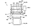
そして、図1及び図2に示すように、各第一搬送ラインの途中でフィリング供給装置8a、8b、9a、9bのフィリング供給位置よりも下流側で各第二搬送ラインの前方先端が合流する箇所には、フィリングを載置した1枚の耳付シート状食パン片w1上に他の1枚の耳付シート状食パン片w1を載せた菓子パン中間品w2を形成する食パン重ね置き装置13が設けてある。この食パン重ね置き装置13は、各第一搬送ライン4a、4b上の1枚の耳付シート状食パン片w1がその対応する食パン重ね置き装置13の近傍に達したことをセンサ14が検出し、この検出信号に基づいて作動する食パン移載機構15が、第一搬送ライン4a、4b上の1枚のシート状食パン片w1の真下へ第二搬送ライン5a、5b上の1枚の耳付シート状食パン片w1を重ね置き状に移載するのである。
Then, as shown in FIG. 1 and FIG. 2, the front ends of the second transport lines merge downstream of the filling supply positions of the filling supply devices 8a, 8b, 9a, and 9b in the middle of each first transport line. In the place, there is provided a
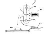
より詳しくは、図5乃至図7に示すように、第二搬送ライン5a、5bの先端61は、ローラコンベアとして構成し、上記のように、第二搬送ライン5a、5bの食パン片w1の搬送方向が上から見て第一搬送ライン4a、4bの食パン片w1の搬送方向と同一になり、かつ横から見て第一搬送ライン4a、4bの食パン片w1の搬送方向に対して下り傾斜になるように、第一搬送ライン4a、4bの途中箇所の特定高さ位置に配置されている。
More specifically, as shown in FIGS. 5 to 7, the leading
そして、重ね置き装置13は、第一搬送ライン4a、4bに設けられ、第一搬送ライン上の食パン片w1が第二搬送ライン5a、5bの先端位置に対して所定位置に来たことを検知するセンサ14と、第二搬送ライン5a、5bに設けられ、その先端61に至った食パン片w1を停止させるとともにセンサ14の検知に基づいて所定のタイミングで停止解除して、第二搬送ライン5a、5bからの食パン片w1の先端を第一搬送ライン4a、4bで搬送される食パン片w1の先端に合致させて重ね合わせるようにする食パン移載機構15としての上ストッパ60とを備えて構成されている。
上ストッパ60は、板状に形成され、第二搬送ライン5a、5bの先端61よりも前方に設けられている。これにより、先端61とストッパ60との間に空間eが設けられている。上ストッパ60は、エアシリンダ装置60aで上下に駆動される。
Then, the stacking
The
また、この重ね置き装置13において、第一搬送ライン4a、4bに、食パン片w1の重ね合わせの際、第二搬送ライン5a、5bの先端61よりも前方で第一搬送ライン4a、4bの食パン片w1の先端に係合して一時的に停止させる下ストッパ62が設けられている。即ち、食パン重ね置き装置13に於ける第一搬送ライン4a、4bを、幅狭の無端搬送ベルトコンベアとし、又は相互に間隔をあけた複数本の無端搬送ベルトコンベアとすると共に、その両脇及び/又は当該間隔に1本または複数本の棒状の下ストッパ62を出没可能に設けている。下ストッパ62は、コンベアからエアシリンダ装置63によって出没可能に設けられ突出時に食パンの先端に当接する一対のロッドで構成されている。
Further, in the stacking
更に、重ね置き装置13において、上ストッパ60の後方に、食パン片w1を押える押さえローラとして上流側押えローラ64及び下流側押えローラ65が設けられている。各押えローラ64、65は回転軸64a、65aに所定間隔で一対設けられ円盤状に形成されたものである。上流側押えローラ64の回転軸64aはブラケット66に設けた長孔67に回転可能かつ上下動可能に軸支され、下流側押えローラ65の回転軸65aはブラケット68に回転可能に軸支されている。
Further, in the stacking
これにより、各第二搬送ライン5a,5bの各先端部から前方にわずかに離間した位置に食パン移載機構15としての上ストッパ60が上下動可能に設けられ、該上ストッパ60が降下状態で第二搬送ライン5a,5bの各先端部で1枚ずつ耳付シート状食パン片w1の進行を阻止して待機させ、各第一搬送ライン4a,4b上の1枚の耳付シート状食パン片w1が前記先端位置に対して所定位置に来たことをセンサ14が検出したとき、この検出信号に基づいて上ストッパ60が上昇して、第二搬送ライン5a,5bの各先端部で待機していた1枚の耳付シート状食パン片w1,w1を、第一搬送ライン上の1枚のシート状食パン片w1,w1の真上へ重ね置き状態に移載する。
Thereby, the
この際には、各第一搬送ライン4a,4b上の耳付シート状食パン片w1,w1が前記第二搬送ラインの先端位置に対して所定位置、すなわち各食パン重ね置き装置13の近傍に達したことをセンサ14が検出したとき、この検出信号に基づいて、下ストッパ62を幅狭の、または複数本の無端搬送ベルトコンベア上にその両脇及び/又はその間隔から出現させて第一搬送ライン4a,4b上の耳付シート状食パン片の進行を阻止して待機させておく。そして、この第一搬送ライン4a,4b上に待機させた耳付シート状食パン片w1,w1に、上述したとおり、上ストッパ60の上昇により、第二搬送ライン5a,5bの先端部で待機していた1枚の耳付シート状食パン片w1,w1を重ね置き状に移載する。
At this time, the sheet-like bread pieces w1 and w1 with ears on each of the first transport lines 4a and 4b reach a predetermined position with respect to the leading end position of the second transport line, that is, the vicinity of each
図1,図2及び図8に示すように、重ね置き手段13において、食品用抜き型装置の上流には、重ね合わされた2枚の食パン片w1,w1の重ね位置を再度調整する重ね位置調整機構70が設けられている。
重ね位置調整機構70は、前記第一搬送ラインの重ね合わされた食パンの移動径路にその下側から進出し食パンを前後から挾持する複数のフィンガ71と、フィンガ71を移動径路に所定時間進出、維持させて退出させるフィンガ進退動部72と、移動径路に進出したフィンガ71の上流側の左右一対を前方に移動させて食パンを挾持するとともに挾持後に後方に後退させるフィンガ挾持駆動部73と、フィンガ挾持駆動部73を支持するフィンガ進退動部72を移動経路に進出したフィンガ71の上流側左右一対の前方移動に同期して、コンベアによる食パンの移動と同速で下流側に移動させ、フィンガ71の前記食パンの移動経路からの退出後にこれを上流側に戻す追従駆動部76とを備えて構成されている。フィンガ71は、図1に示すように、食パンのコーナに当接できるように断面L字状に形成されて、前後に一対ずつ設けられている。
As shown in FIG. 1, FIG. 2 and FIG. 8, in the stacking
The stacking
フィンガ挾持駆動部73は、ピストン73a及びシリンダ73bからなるエアシリンダ装置で構成され、エアシリンダ装置のピストン73aの先端に上流側の一対のフィンガ71を設け、エアシリンダ装置のシリンダ73bに下流側の一対のフィンガ71を設け、ピストン73aに固定された上流側のフィンガ71の前方移動により食パンを挾持する。
フィンガ進退動部72は、ピストン72a及びシリンダ72bからなるエアシリンダ装置で構成され、当該エアシリンダ装置のピストン72aの先端にフィンガ挾持駆動部73のシリンダ73bを設け、当該エアシリンダ装置のシリンダ72bを追従駆動部76のエアシリンダ装置のピストン76aの先端に固定している。ピストン72aの上下の進退動によりフィンガ挾持駆動部73を上下に進退動させ、進出時にフィンガ71を移動径路に所定時間滞在させる。また、フィンガ進退動部72のシリンダ72bは、食パンの移動方向に沿って移動可能に支持部材74を介してレール75に支持されている。
追従駆動部76は、ピストン76a及びシリンダ76bからなるエアシリンダ装置で構成され、当該エアシリンダ装置のピストン76aの先端にフィンガ進退動部72のシリンダ72bを設け、当該エアシリンダ装置のシリンダ76bを機台に固定している。このエアシリンダ装置のピストン76aの前後の進退動によりフィンガ進退動部72のシリンダ72bをレール75上で往復動させ、該シリンダ72bを、前記移動経路に進出したフィンガ71の上流側左右一対の前方移動に同期して、コンベアによる食パンの移動と同速で下流側に移動させ、前記フィンガ71の移動経路からの退出後に上流側に戻すものである。
The finger holding
The finger advancing / retracting
The follow-up driving
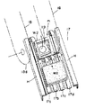
而して、上記第一搬送ライン4a、4bの先端の前方側には上記食パン重ね置き装置13により位置調整された前記菓子パン中間品w2を押圧し、且つ切離しする食品用抜き型装置16が配置されるのであり、該装置16は、図1及び図2,図9乃至図12に示すように、菓子パン中間品w2を第一搬送ラインから受け入れて下側抜き型に渡すように作動する受渡し搬送部17と、一つの搬送手段をなす左右一対の無端状の搬送チェーン18、18と、該搬送チェーン18、18の長さ方向に特定距離間隔でそれぞれに装着された複数の下側抜き型19と、左右の前記搬送チェーンの18、18の上張り部18aの上方に配置され前後へ往復移動されるようになされた案内支持体20と、この案内支持体20下面箇所へ上下移動可能に垂下状に設けられた上側抜き型21と、この上側抜き型21の下流側の案内支持体20下面箇所に上下移動可能に垂下状に設けられた焼き印22とを備えたものとなされている。
各下側抜き型19はその左右両側面でそれぞれ前記左右の搬送チェーン18、18の内側に取付けられる。
本実施の形態では、上述した通り、第一搬送ライン、第二搬送ライン及び食パン重ね置き装置が二列並んで設けられているのに対応して、一つの食品用抜き型装置において、受渡し搬送部17、左右一対の無端搬送チェーン18、18からなる搬送手段、該搬送手段に装着した複数の下側抜き型19の列、上側抜き型21及び焼き印22が二列並んで設けられている。
Thus, a
Each lower punching die 19 is attached to the inside of the left and
In the present embodiment, as described above, in response to the first transport line, the second transport line and the bread stacking device being provided in two rows, in one food punching device, the delivery
ここに、受渡し搬送部17は、図1及び図2,図9及び図10に示すように、第一搬送ライン4a、4bの下流側先端へ延設され、これと同一水平状態の一定長さ範囲で回動される搬送コンベアであり、具体的には、図13に示すように、搬送コンベアの複数本(3本以上)のコンベア(図示例では17a、17b、17c、17dの4本)を側壁フレームH、Hに対し並列状態に配置すると共に、この両端17a、17d側を除く内側のコンベア17b、17cを両端のそれより下流部分において長さの短いものとなすことにより、下流側の内側にコンベアの無い空間m部分を形成させ、該空間m部分ではシート状物体(菓子パン中間品w2)は両端側コンベア17a,17bでのみ支承されるようになすと共に、該空間mの下方部分には次述する無端状搬送手段の円弧状部18dが位置されるものとなし、無端搬送チェーンに一定距離間隔で取付けられて回動する下側抜き型19が順次その上面を上方へ向けて支障なく突出されるものとなし、このときに両端側のコンベア17a、17b上に於けるシート状物体(菓子パン中間品w2)の中央部を下側抜き型上へ受け取るようになさしめる構成である。
Here, as shown in FIG. 1, FIG. 2, FIG. 9, and FIG. 10, the delivery /
また、図2及び図9に示すように、受渡し搬送部17のベルトコンベアの上流側において、下側抜き型19に移載される前の菓子パン中間品を一時的に停止させるストッパ79が設けられている。このストッパ79は、コンベア間からエアシリンダ装置79aによって上下に進退可能に設けられ進出時に食パンの先端に当接する一対のロッドで構成されている。
Further, as shown in FIGS. 2 and 9, a
而して、無端搬送チェーン18、18は、図9及び図10に示す如く定置台23上の特定位置にスプロケットを介して特定楕円軌道上での周回移動可能に、装着させると共に受渡し搬送部17と同期して左回りf1へ連続駆動されるものとなされる。
As shown in FIGS. 9 and 10, the
各下側抜き型19は搬送チェーン18に対応して設けられると共に、各搬送チェーン18の水平方向へ安定的に支持されるのみならず、両端の支持案内軌道部材24の外周縁箇所では、受渡し搬送部17からのシート状物体を安定的に受け取ったり、受け渡したりするものとなされるのである。
Each lower punching die 19 is provided corresponding to the
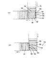
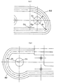
詳しくは、図9乃至図11に示すように、下側抜き型19を所定間隔で複数設け、各下側抜き型19の搬送手段を、各下側抜き型19の左右両側を軸支して連結する左右一対の無端状の搬送チェーン18と、搬送チェーン18を循環させる一対のスプロケット80を備えて構成し、各下側抜き型19の一外側壁に設けたアームを介してその先端部に突起81を設け、各下側抜き型19の突起81に係合し各下側抜き型19の軌道を搬送チェーン18の軌道とは異なって規定するガイドレール82を搬送チェーン18の径路に隣接して設けている。特に、ガイドレール82は、その上流側のスプロケット80に対応する部位82aが、下側抜き型19が受渡し搬送部17からの菓子パン中間品を受け取る際に下側抜き型19の上面ができるだけ早い段階から水平になるように、スプロケット80に沿う円軌道ではない別の軌道に形成されている。具体的には、図11(a)に示すように、上流側のスプロケット80に対応する部位において、前記ガイドレール82を、上面を下に反転させて搬送されてきた下側抜き型19が該スプロケット80の中心を通過して、上面が上になるようにまた反転を開始したときから間もなく、該スプロケット80が描く円軌道の中心点(O1)を斜め下方向に45度偏心させた点を中心点(O2)として、該スプロケット80の中心点(O1)を中心とする突起81の円軌道の半径(R1)よりも長い径(R2)で、該スプロケット80の中心点よりも外方に90度の角度まで円を描いたときの軌道として形成するのである。これにより、下側抜き型19を、受渡し搬送部17からの菓子パン中間品を受け取り易い姿勢にすることができ、受け取りが確実に行なわれるようにしている。
また、前記ガイドレール82を、その下流側のスプロケット80に対応する部位において、前記下型抜き型19が菓子パンを引き渡す際に、該下側抜き型19の上面ができるだけ遅い段階まで反転のため傾斜しないように、該スプロケット80に沿う円軌道ではない別の軌道を有して形成することが有効である。具体的には、図11(b)に示すように、下流側のスプロケット80に対応する部位において、前記ガイドレール82を、上面を上にして水平に搬送されてきた下側抜き型19が該スプロケット80の中心を通過した後もできるだけ直線的な軌道とし、しかる後に該スプロケット80が描く円軌道に沿った円軌道として形成するのである。これにより、下側抜き型19の上面ができるだけ遅い段階まで水平か、急傾斜するのを回避することができるようになるので、下側抜き型19を、菓子パンをその下流の取り出し搬送コンベア43へ引き渡し易い姿勢にすることができ、この引き渡しが容易になる。
該ガイドレール82は、上流側及び下流側の両スプロケット80に対応する部位の他にも、下側抜き型19が下流側のスプロケット80から上流側のスプロケット80まで戻ってくる無端状搬送チェーン18の下張り部18bの経路のほぼ全長にわたって隣接して設けられており、下側抜き型19の戻り搬送を安定化させている。そして、上下一対の抜き型19,21により菓子パン中間品w2を挟み付け押圧する無端状搬送チェーンの経路にはない。
More specifically, as shown in FIGS. 9 to 11, a plurality of
Further, the
The
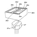
各下側抜き型19の詳細は次の通りである。図14乃至図18に示すように、下側抜き型は、型本体部25と、型本体部25に設けられ食パンの周囲を圧着する矩形枠状の型要部26と、型本体部25に設けられ型要部26内に没入する没入位置及び型要部26から突出して型要部26で圧着された食パンを型要部26から押出す押出し位置の2位置に移動可能な押出し体27と、押出し体27を常時没入位置に付勢するスプリング31とを備えて構成されている。
The details of each lower punching die 19 are as follows. As shown in FIGS. 14 to 18, the lower punching die includes a mold
即ち、図14に示すように、型本体部25とこれの上面に交換装着可能に固定された型要部26とを有している。そして、型本体部25の上部中心箇所には案内凹部25aと型要部26の中心箇所には縦向きの案内孔26aを形成して、これら案内孔26a内に図16に示す直径方向の深溝27aの形成された押出し体27を遊嵌すると共に、型本体部25の下部の肉厚部に2つの縦向き孔25b、25bを形成してこれらの縦向き孔25b、25bのそれぞれに摺動棒28、28を内挿し、各摺動棒28の上端部を前記押出し体27の下面に螺着させ、これら摺動棒28、28の下端部を連結部材29で連結し、この連結部材29の下面側にローラ30を設けると共に、この連結部材29と型本体部25の下面との間に位置した各摺動棒28部分に圧縮スプリング31を外挿した構成となしてある。
That is, as shown in FIG. 14, a mold
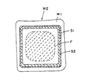
一方、型要部26は、図16に示すように、四角体となされて、その上面には外周縁に位置された比較的細い切断面部26bと、この切断面部26bの内側にはこれに沿って位置された比較的浅い凹み面をなす押圧面部26c、及び、この押圧面部26cの内側に位置されて比較的深く形成された四角状の凹み部26dを形成されている。この凹み部26dは案内孔26aと連通され、前記押出し体27が内部で上下変位し得るものとなされている。
On the other hand, as shown in FIG. 16, the
また、図2,図9及び図10に示すように、本装置には、食パンの圧着終了後に押出し体を移動させる押出し体移動機構90が設けられている。押出し体移動機構90は、各押出し体27に設けられたカムフォロアとしての上記ローラ30と、搬送手段の搬送終了端部に設けられ押出し体27のローラ30に係合してローラ30を押圧し、押出し体27を押し出し位置に移動させるカム板38とを備えて構成されている。
Further, as shown in FIGS. 2, 9 and 10, the present apparatus is provided with an extruded
即ち、各搬送チェーン18、18の下流側の両スプロケット80の間には縦向きのカム板38が設けてあり、このカム板38は、横から見ると略涙形状(ラッキョウ形状)で、頭部を下流に向けて横たわっているような形状であり、その頭部の外周縁が下側抜き型19のローラ30に係合して押出し体27を型本体部25に対して上下変位させるもので、下側抜き型19が各搬送チェーン18、18の上張り部18aの下流側位置p2に達した時点から各搬送チェーン18、18の円弧状部位18を過ぎる時点までの区間に限ってローラ30をカム板38の頭部外周縁に係合させて押圧し、押出し体27を押し出し位置に移動させ、型要部26の上面側へ向けて押し上げた状態を維持するものとなされている。
That is, a
他方、案内支持体20は、図2,図9及び図12に示すように、定置台23の上部に固定された前後向き案内軌道部32を介して往復駆動機構100により前後方向の往復移動可能になされており、また、案内支持体20の前後箇所には上側抜き型21及び焼き印22のそれぞれを単独に上下移動させるための動力駆動シリンダ装置33、34が装設されている。
本実施の形態では一つの案内支持体20に幅方向に並列して二つずつ上側抜き型21,焼き印22を設けている。
On the other hand, as shown in FIGS. 2, 9 and 12, the
In the present embodiment, two
ところで上側抜き型21は次のように構成されているのであって、即ち、図9,図14及び図18に示すように、動力駆動シリンダ装置33の出力部に結合固定された型本体部35と、これの下面に交換装着可能に固定された型要部36とを有しており、型要部36は先の下側抜き型19の型要部26と同様に四角体となされて下面を前記型要部26の上面の形態と符合する対称的な形態となされる。而して、型要部36の下面は、図14に示すように、その外周縁に位置された切断面部36a、この切断面部36aの内側に沿って位置された比較的浅い凹み面をなす押圧面部36b、及び、この押圧面部36bの内側に比較的深く形成され四角状となされた凹み部36cを具備したものとなされる。
By the way, the upper punching die 21 is configured as follows, that is, as shown in FIGS. 9, 14 and 18, the die
これに対し、焼き印22は印本体部37を動力駆動シリンダ装置34の出力部に結合固定されると共に印本体部34の内方に図示しないヒータを装設され、印本体部37の下面に前記ヒータで加熱される印部を形成したものとなされている。
また、前記無端状搬送チェーン18の上張り部18a及び下張り部18bの軌道に沿って、該無端状搬送チェーン18に連結された下側抜き型19、特にその型本体部25の外側面周囲に横方向に凸状に形成された外側面突端部25cを戴置して摺動する下側抜き型レール91を、該無端状搬送チェーン18の上張り部18a及び下張り部18bにそれぞれ平行して設けている(図10及び図14参照)。これにより、下側抜き型19の搬送をより一層安定化させるとともに、該上張り部18aにおいて、下側抜き型19に上側抜き型21が降下して菓子パン中間品w2を挟み付け押圧するにあたり、より一層強い力が加わるようにすることができる。
On the other hand, in the
Along the trajectory of the upper end portion 18a and the
案内支持体20の往復駆動機構100は、図12に示すように、クランク機構101で構成されている。クランク機構101は、装置本体に設けられ案内支持体20の移動方向に対して直交する軸線を有した回転軸102を有した駆動モータ103と、駆動モータ103の回転軸102に同軸に設けられ駆動モータ103によって回転させられる円盤104と、一端が案内支持体20に軸支されるとともに他端が円盤104の軸線に対して偏心した位置に軸支されるリンク105とを備えて構成されている。
The
また、図9に示すように、各搬送チェーン18、18の上張り部18aの下流側端部の近傍には第一干渉手段39を設けてあり、該干渉手段39は、図15に示すように、前記定置台23に固定された本体部材40と、これに固定された左右一対の下向き張出部材41a、41bとからなっている。この際、一対の下向き張出部材41a、41bは下側抜き型19の軌道の左右外側近傍に位置するように前下方へ向けて延伸されると共に高さ位置及び左右方向距離L1の変更調整可能となされている。
As shown in FIG. 9, a first interference means 39 is provided near the downstream end of the upper part 18a of each of the
そして、各搬送チェーン18、18の円弧状部位18cの下半分範囲箇所に第二干渉手段42が定置台23に固定されている。この第二干渉手段42は第一干渉手段39と同様に、定置台23下部に固定された本体部材42aと、この本体部材42aの左右箇所から前上方へ向けて張り出された左右一対の上向き張出部材42bとからなっており、左右一対の上向き張出部材42bは下側抜き型19の軌道の左右外側近傍に位置するように前上方へ向けて延伸されると共に、高さ位置及び左右方向距離の変更調整可能となされている。
The second interference means 42 is fixed to the stationary table 23 in the lower half range of the
そして、食品用抜き型装置16の前方側で搬送チェーン18、18の円弧状部18c、18cの前端近傍から前方へ菓子パンw3の取出し搬送コンベア43が延設されており、また搬送チェーン18、18の円弧状部18c、18cの下側から横方へ向けて食パン耳部w4の取出し搬送コンベア44が延設されている。
A
従って、この菓子パンの製造装置により菓子パンを製造するときは例えば次のように行う。図20に示すフローチャートを参照し説明する。
フィリング供給装置8a、8b、9a、9bのタンク10にフィリングFを収容させると共に各食パンスライス送出装置1A、1Bに3斤分の棒状食パンwを供給しておく。なお、フィリングFや棒状食パンwが消費されたときは適宜に補充する。
この状態で各部を作動状態とするのであり、これにより食パンスライス送出装置1A、1Bではスライサ2が棒状食パンwをスライスして適当厚さの耳付シート状食パン片w1となし、一方では第一及び第二搬送ライン4a、4b、5a、5bが連続送り移動を開始する。この第一及び第二搬送ライン4a、4b、5a、5b上には、各食パンスライス送出装置1A、1Bの送出機構3が、先にスライサで形成された耳付シート状食パン片w1の1枚ずつを送り出して順次に載置する。
Therefore, when a confectionery bread is manufactured by this confectionery bread manufacturing apparatus, the following operation is performed, for example. This will be described with reference to the flowchart shown in FIG.
The filling F is accommodated in the
In this state, the respective parts are brought into the operating state, whereby the
第一搬送ライン4a、4bに載置された1枚の耳付シート状食パン片w1が順次にフィリング供給位置に到達するが、1枚の耳付シート状食パン片w1がこのフィリング供給位置に到達してフィリング供給装置8a、8b、9a、9bのポンプ11が作動してタンク10内のフィリングFを第一搬送ライン上の1枚の耳付シート状食パン片w1の上面に、クリームやジャムなどのフィリングFが予め定められた量だけ供給される。この供給は第一搬送ライン4a、4bに載置された1枚の耳付シート状食パン片w1毎に行われる。この際、フィリング供給装置8a、8b、9a、9bは各第一搬送ライン4a、4b毎にそれぞれ8a及び9a,8b及び9bのうちの少なくとも1台作動させるようにする。また、1枚の耳付シート状食パン片w1毎に2種類のフィリングを供給しようとするときは、各第一搬送ライン4a,4b毎にそれぞれ8a及び9a,8b及び9bの2台ずつフィリング供給装置を作動させる。
One piece of bread sheet w1 with ears placed on the first transport lines 4a and 4b sequentially reaches the filling supply position, but one piece of bread sheet w1 with ears reaches this filling supply position. Then, the
こうして、フィリングFを供給された各耳付シート状食パン片w1は各第一搬送ライン4a、4bの移動により食パン重ね置き装置13、13の位置まで順次に搬送される。
In this way, the sheet-like bread slices w1 with the ears supplied with the filling F are sequentially transported to the position of the
この第一搬送ライン4a、4bの作動の一方では、第二搬送ライン5a、5bがこれに載置された耳付シート状食パン片w1を搬送するのであり、これにより各耳付シート状食パン片w1は上述した通り、各第一搬送ライン4a、4b上方の特定高さ位置に配置されている各第二搬送ライン5a、5bの先端に到達する。 While one of the operations of the first transport lines 4a and 4b, the second transport lines 5a and 5b transport the sheet-like bread slices w1 with ears placed thereon, and thereby each of the sheet-like bread slices with ears. As described above, w1 reaches the tip of each of the second transport lines 5a and 5b arranged at a specific height above each of the first transport lines 4a and 4b.
この搬送過程において、第二搬送ライン5a、5bにおいて直角に折れて食パンの搬送方向を直角に変換する直角ラインがあるところでは、図3及び図4に示すように、方向変換機構50のアクチュエータ57が作動し、ロッド53を進退動させる。ロッド53の進出時には、ロッド53はローラ52の上端から突出してローラコンベア51の進行方向に直行する方向に食パン片w1を押す。これにより、進行方向が直角に異なる下流のコンベアに食パン片w1が受け渡され、方向変換が行なわれる。この場合、ロッド53は、その軌道がガイドレール55で規定されて移動するが、ガイドレール55により押出端側でローラ51の上端より下側に没入させられる。そのため、下流のコンベアに干渉することなく十分に食パン片w1を押すことができ、確実に受け渡して方向変換が行なわれる。また、ロッド53は、保持体54にくし歯状に複数設けられているので、食パン片w1の後端の全長にわたって押すことができ、姿勢を崩すことなく確実に押すことができる。また、アクチュエータ57のシリンダ57bは、ロッド53の軌道に追従しうるように回動可能するので、動作が円滑に行なわれる。
In this transport process, where there is a right-angle line that is bent at a right angle in the second transport lines 5a and 5b and changes the transport direction of the bread to a right angle, as shown in FIGS. Operates to move the
ところで、食パン重ね置き装置13、13では上述した通りセンサ14が作動し、この検出信号に基づいて第一搬送ライン4a、4bに載置されて搬送されている耳付シート状食パン片w1の上へ上記第二搬送ライン5a、5bの先端まで搬送されて待機させられていた耳付シート状食パン片w1が降下して重ね合わせ状に移載されてるのであり、2枚の耳付シート状食パン片w1、w1の間にフィリングFの供給された菓子パン中間品w2が形成されるものとなる。
By the way, the
詳しくは、先ず、図7(a)に示すように、第二搬送ライン5a、5bにおいてはその先端61に至った食パン片w1が上ストッパ60によって停止させられる。この場合、食パン片w1が押えローラ64,65によって押えられるとともに、第二搬送ライン5a、5bの先端61と上ストッパ60との間に空間eがあるので食パン片w1の先端部が空間に露出して停止させられる。
この状態で、第一搬送ライン4a、4bに設けられたセンサ14が第二搬送ライン5a、5bの先端位置に対して食パン片w1が所定位置に来たことを検知すると、下ストッパ62が所定のタイミングで突出させられ第一搬送ライン4a、4bで搬送される食パン片w1を停止させるとともに、図7(b)に示すように、上ストッパ60を所定のタイミングで停止解除し、第二搬送ライン5a、5bの先端に至った食パン片w1をその先端が第一搬送ライン4a、4bで搬送される食パン片w1の先端に合致させて重ね合わせるようにする。その後、図7(c)に示すように下ストッパ62を後退させる。
Specifically, first, as shown in FIG. 7A, in the second transport lines 5 a and 5 b, the bread piece w 1 reaching the
In this state, when the
この場合、第二搬送ライン5a、5bからの食パン片w1が降下するが、上側の食パン片w1が上ストッパ60によって停止させられてから降下するので、下側の食パン片w1とのタイミングを調整でき、そのため、確実に上下の食パン片w1の先端同士を合わせることができるようになる。
更に、上側の食パン片w1の先端は、第二搬送ライン5a、5bの先端と上ストッパ60との間の空間eに露出して停止させられた状態から降下するので、上側の食パン片w1の先端位置を下側の食パン片w1に極めて近い位置に位置させることができ、そのため、降下距離を短くできるので、それだけ、より正確に上下の食パン片w1の先端同士を合わせることができるようになる。
更にまた、下側の食パン片w1が下ストッパ62によって、停止させられて、上側からの食パン片w1を待ち受けるようになるので、この点でもより正確に上下の食パン片w1の先端同士を合わせることができるようになる。
該重ね置き装置13においては、上述したとおり、前記上ストッパ60の後方に設ける押えローラとして、上流側押えローラ64及び下流側押えローラ65という二つの押えローラを設けることが望ましい。まず、上流側押えローラ64は、第2搬送ライン5a、5bの食パン片w1が下流側押えローラ65をくぐって第一搬送ライン4a、4b上へ降下するときに、該食パン片w1の後部を押えることにより、該食パン片w1の先端が前傾斜して撓むことにより該食パン片w1が第一搬送ライン4a、4b上の食パン片に降下して重ね合わせられたときに、上下の食パン片の先端同士の重ね合せにズレが生じることを極力防止することができるようになる。
また、下流側押えローラ65は、第二搬送ラインに設けられた上ストッパ60が、第二搬送ライン5a、5bの各先端部に至って、進行を阻止して待機していた食パン片w1、w1の停止解除による上昇をするときに、該食パン片の先端部付近を押えることにより、該食パン片の該ストッパと接触していた先端がまさつや粘着により持ち上げられて該食パン片が撓むことにより、降下のタイミングが狂い、該食パン片w1、w1が第一搬送ライン4a、4b上の食パン片に重ね合わされたときに、上下の食パン片の先端同士の重ね合せにズレが生じることを極力防止することができるようになる。
上流側押えローラ64の回転軸64aは、ブラケット66に設けた長孔67に上下動可能に軸支することにより、上流側押えローラ64が上下に揺動し得るようにしている。このようにすることにより食パン片w1を押えるときや厚さの厚い食パン片でも過度に食パン片にストレスをかけることがなくなる。
前記押えローラは、回転軸の外周面が直接食パン片と接触して押えるような構成(円柱状又は円筒状)としてもかまわないが、本実施の形態のように、回転軸に設けた幅狭の円盤状の構成とすることが望ましい。このように幅狭の押えローラとすることにより、食パン片と接触する面積を小さくして食パン片にストレスをかけることがなくなる。
In this case, the loaf of bread w1 from the second transport lines 5a and 5b descends. However, since the loaf of upper bread w1 is stopped after being stopped by the
Furthermore, since the tip of the upper bread piece w1 is exposed to the space e between the tips of the second transport lines 5a and 5b and the
Furthermore, since the lower bread piece w1 is stopped by the
In the stacking
The downstream
The rotation shaft 64a of the
The pressing roller may have a configuration (columnar or cylindrical) in which the outer peripheral surface of the rotating shaft comes into direct contact with the bread piece and presses the same. However, as in the present embodiment, the narrow width provided on the rotating shaft is reduced. It is desirable to adopt a disk-like configuration. By using the pressing roller having such a small width, the area in contact with the bread piece is reduced, so that stress is not applied to the bread piece.
上記は順次連続して行われ、重ね合わされた菓子パン中間品w2はさらに前方へと搬送される。 The above operations are sequentially and continuously performed, and the superimposed confectionery bread intermediate product w2 is further transported forward.
次に、菓子パン中間品w2は、重ね位置調整機構70に至り、重ね合わされた2枚の食パン片の重ね位置が再度調整される。ここでは、図8(a)(b)に示すように、先ず、フィンガ進退動部72がフィンガ71を菓子パン中間品w2の移動径路に進出させる。この状態で、図8(c)に示すように、フィンガ挾持駆動部73が、移動径路に進出したフィンガ71の上流側の左右一対を前方に移動させるとともに、これと同期して追従駆動部76がフィンガ進退動部72をコンベアによる食パンの移動と同速で下流側に移動させて菓子パン中間品w2を挾持する。
このため、上記の重ね合わせで、多少上下の食パン片w1間にずれがあっても、これが修正され、上下の食パン片w1が確実に合致するようになる。この場合、フィンガ71は、図1に示すように、食パン片w1の4つのコーナ部を押えるので、左右前後の押さえが確実になり、上下の食パン片w1がより一層確実に合致するようになる。
フィンガ71の挾持が終わると、フィンガ挾持駆動部73が、フィンガ71の上流側の左右一対を後方に後退させるとともに、フィンガ進退動部72がフィンガ71を食パンの移動径路から退出させる。そして、追従駆動部76がフィンガ進退動部72を上流側に戻すようにする。
Next, the confectionery bread intermediate product w2 reaches the stacking
For this reason, even if there is some deviation between the upper and lower bread pieces w1 in the above-mentioned superposition, this is corrected, and the upper and lower bread pieces w1 are surely matched. In this case, since the
When the
上記は順次連続して行われ、重ね合わされた菓子パン中間品w2はさらに前方の食品抜き型装置16へと搬送される。
The above operations are sequentially and successively performed, and the superimposed confectionery bread intermediate product w2 is further conveyed to the
食品用抜き型装置16は、図1,図2,図9及び図10に示すように、その上流側に受渡し搬送部17が設けてあり、上記第一搬送ライン4a、4bの先端に到達する菓子パン中間品w2を順次に受け取り、受渡し搬送部17と同期して回動される搬送チェーン18、18の上流側p1で下側抜き型19の上面に移載する。この受渡し搬送部17においては、下側抜き型19の上流側でストッパ79が進出し、下側抜き型19に移載される前の菓子パン中間品w2を一時的に停止させる。そのため、菓子パン中間品w2の下側抜き型19上への受渡しタイミングが調整され、菓子パン中間品w2の中央部が下側抜き型19の中央上へ確実に位置させられる。
As shown in FIGS. 1, 2, 9, and 10, the
この場合、各下側抜き型19は、その突起81が搬送チェーン18の軌道とは異なって規定するガイドレール82によってガイドされていく。特に、ガイドレール82は、その上流側のスプロケット18に対応する部位が、下側抜き型19が受渡し搬送部17からの菓子パン中間品w2を受け取る際に下側抜き型19の上面ができるだけ早い段階から水平になるように、スプロケット18に沿う円軌道ではない別の軌道に形成されているので、下側抜き型19を、受渡し搬送部17からの菓子パン中間品w2を受け取り易い姿勢にすることができ、受け取りが確実に行なわれる。
In this case, each lower punching die 19 is guided by a
而して、下側抜き型19がp1から下流側へ距離L1(図9参照)移動して第一特定位置p3に達すると、案内支持体20の動力駆動シリンダ装置33が直ちに伸長されて上側抜き型21が降下作動されて、図18に示すように下側抜き型19と上側抜き型21とが正対状となって下側抜き型19上の菓子パン中間品w2を強力に挟み付ける。食パンを挟む場合の圧力は、3〜10kg/cm2好ましくは4〜6kg/cm2である。この挟み付け状態は搬送チェーン18、18及び案内支持体20の同調した下流側への移動により、再び距離L2(図9参照)だけ搬送チェーン18、18が移動する間中継続される(具体的には本実施の態様では0.5〜1.0秒間、好ましくは0.7〜1.0秒間である)のであり、この距離L2の移動が終了して下側抜き型19が第二特定位置p4に到達したとき、動力駆動シリンダ装置33が短縮作動されて上側抜き型21が上昇作動される。
When the lower punching die 19 moves a distance L1 (see FIG. 9) from p1 to the downstream side and reaches the first specific position p3, the power
この際、上側抜き型21の下面全体と下側抜き型19の上面全体とが正対して、該上下の抜き型の押圧面全体で菓子パン中間品w2を任意な一定時間に亘って継続的な押圧状態下になすため、図17に示す如く菓子パン中間品w2の上下の耳付シート状食パン片w1、w1の圧着対象位置s2を確実に圧着させたものとなすほか、切断対象位置s1で確実に切断させることができる。このときに、該下型抜き型19は、その型本体部25の外側面突端部25cにおいて、前記下型抜き型レール91に載置されているため、菓子パン中間品w2の押圧にあたり、より強い力が加わるようにすることができる(図10及び図14参照)。このとき、菓子パン中間品w2の圧着対象位置s2の内方箇所は凹み部26d、36c内にて殆ど押圧力を付与されないのであり、この結果として下側抜き型19上にふっくら感のある四角状の菓子パンw3が形成されるものとなり、且つ下側抜き型19の側面周囲に図9、図15及び図18に示すような食パン耳部w4が残された状態となる。
At this time, the entire lower surface of the
前記上側抜き型21の上昇作動に伴って、案内支持体20が上流側の原位置へ復帰されるのであり、以下は同様動作の繰返しとなる。上記では動力駆動シリンダ装置33の作動についてのみ説明したが、二回目からの繰返しでは必要に応じ、動力駆動シリンダ装置34も伸長させて焼き印22が付与されるようにする。
The
この際、焼き印22は過度に長く下降状態を保持されると、菓子パンw3の印表示が黒こげとなるため必要に応じて上側抜き型21よりも早い時点で上昇させるようにする。以後、上下の抜き型19、21及び焼き印22による上記処理が下側抜き型19上へ載置された各菓子パン中間品w2毎に繰り返される。
At this time, if the lowering state of the
また、この場合、案内支持体の往復駆動機構は、クランク機構101で構成されているので、往復動が淀みなく確実に行なわれる。特に、図9及び図12に示すように、クランク機構101は、駆動モータ103によって回転させられる円盤104により、リンク105を作動させるので、エアシリンダで往復動させる場合に比較して、往復動の切り返しに淀みがなくなり、そのため、往復動が円滑に行われる。その結果、上側抜き型21と下側抜き型19は、その前記下降・上昇動作とあいまって、継続して菓子パン中間品w2を押圧し周囲圧着予定部位(圧着対象位置s2)を強力に圧着させることができる。
In this case, since the reciprocating drive mechanism of the guide support is constituted by the
そして、1つの下側抜き型19が第二特定位置p4からさらに前方へ向けて送り移動され図9に示す前方端位置p2の近傍に達したとき、この下側抜き型19のローラ30が横から見ると略涙形状(ラッキョウ形状)のカム板38の頭部外周縁に押し変位されて押出し体27が凹み部26dを経て下側抜き型19の上面から僅かに突出した状態となって凹み部26d内に嵌り込んだ菓子パンw3の下部を凹み部26dの外方へ押し出すものとなり、このときの押出し体27の下側抜き型19における位置は下側抜き型19が搬送チェーン18の下張り部18bの前方端に到達するまで維持され下張り部18bの後方側へ向かうに伴って押出し体27は凹み部26d内に没入し、下張り部18bの中間位置に到達するまでには凹み部26dの底面より深い位置に変位されるものとなる。
Then, when one lower punching die 19 is further moved forward from the second specific position p4 and reaches near the front end position p2 shown in FIG. 9, the
この場合、押出し体27が凹み部26d内に嵌り込んだ菓子パンw3の下部を凹み部26dの外方へ押し出すので、下側抜き型19から確実に外すことができる。また、押出し体27は、下側抜き型19のローラ30がカム板38に押されることにより突出するので、カムで行なうことから、動作が円滑かつ確実に行なわれる。
また、前記ガイドレール82を、その下流側のスプロケット80に対応する部位において、前記下型抜き型19が菓子パンを引き渡す際に、該下側抜き型19の上面ができるだけ遅い段階まで反転のため傾斜しないように、該スプロケット80に沿う円軌道ではない別の軌道を有して形成している。これにより、下側抜き型19の上面ができるだけ遅い段階まで水平か、急傾斜するのを回避することができるようになるので、下側抜き型19を、菓子パンをその下流の取り出し搬送コンベア43へ引き渡し易い姿勢にすることができ、この引き渡しが容易になる。
In this case, since the extruded
Further, the
ところで、下側抜き型19が搬送チェーン18の円弧状部18cの上半分範囲の前下がり傾斜位置に到達すると、下側抜き型19の上面に載置された状態の菓子パンw3は重力作用により取出し搬送コンベア43上に落下されるか、又は移載されると共に、第一干渉手段39の一対の下向き張出部材41a、41bが下側抜き型19の側面に外嵌された状態の食パン耳部w4を下側抜き型19から抜け出さないように下方へ押さえ付ける(図9及び図15参照)。
By the way, when the lower punching die 19 reaches the front lowering inclined position in the upper half range of the
そして、下側抜き型19が搬送チェーン18の円弧状部18cの下半分範囲の前上がり傾斜位置に到達したとき、第二干渉手段42の一対の上向き張出部材42bが下側抜き型19の側面に外嵌された状態の食パン耳部w4を下側抜き型19から抜き出すように変位させ、取出し搬送コンベア44上に落下させる(図9参照)。
これにより、菓子パンw3は取出し搬送コンベア43により特定場所へ搬出され、また食パン耳部w4は取出し搬送コンベア44により横方へ搬出されるのである。
Then, when the lower punching die 19 reaches the forward rising inclined position in the lower half range of the
As a result, the confectionery bread w3 is carried out to a specific place by the take-out and
上記実施の形態では製品化成形を連続搬送される構成下で説明したが、間欠搬送されるものでも同様に実施可能であり、本発明の実施範囲内とする。
さらには、上記実施の形態では、各第一搬送ラインに2台ずつフィリング供給装置を設ける態様について述べたが、上記実施の形態において、各第一搬送ラインごとに1台ずつフィリング供給装置を追加して(図示しない)、それぞれに3台ずつフィリング供給装置を設けることにより、第一搬送ライン上の耳付シート状食パン片w1の上面に3種類のフィリングを供給するようになすこともできる。この場合に、特に各フィリング供給装置の導管手段の先端吐出口を平板状としてフィリングを幅広の板状に押し出すようにすることにより、耳付シート状食パン片w1の上面に3種類のフィリングを板状に供給して3層の積層状態に載置することもできるし、この耳付シート状食パン片w1にもう一枚の耳付シート状食パン片w1を載せた菓子パン中間品w2を上記食品用抜き型装置で押圧・切離すことにより、3種類の異なるフィリングを積層状態に内包して密閉したサンドイッチを容易に製造することができる。
なお、個別的な変形例について図19を参照して説明すると、図19は変形された下側抜き型19を示す斜視図である。
本例では前記型要部26を取り外し、代わりに別途に用意した型要部26Aを固定したものである。この型要部26Aは先の型要部26の上面の中央に橋渡し部26eが形成してあり、この橋渡し部26eの巾中央に切断面部26bと同一高さで連続した切断面部26b’を形成し、且つこの切断面部26b’の巾方向両側に押圧面部26cに連続した押圧面部26c’が形成してある。その他は同一構造である。
In the above-described embodiment, the description has been made on the configuration in which the productization molding is continuously conveyed. However, the present invention can be similarly applied to an intermittently conveyed product, which is within the scope of the present invention.
Furthermore, in the above-described embodiment, two filling supply devices are provided for each first transport line. However, in the above-described embodiment, one filling supply device is added for each first transport line. Then, by providing three filling supply devices (not shown), three types of fillings can be supplied to the upper surface of the sheet-like bread piece w1 with ears on the first transport line. In this case, in particular, by making the distal end outlet of the conduit means of each filling supply device flat and extruding the filling into a wide plate shape, three types of fillings are formed on the upper surface of the sheet-like bread slice w1 with ears. Can be placed in a three-layered state, and a confectionery bread intermediate product w2 in which another sheet-like bread piece w1 with ears is placed on the sheet-like bread piece w1 with ears is used for the above-mentioned food. By pressing and separating with a punching die device, it is possible to easily manufacture a sealed sandwich in which three different fillings are included in a stacked state.
Note that individual modifications will be described with reference to FIG. 19. FIG. 19 is a perspective view showing a modified lower punching die 19.
In this example, the
またこの場合には、前記上側抜き型の型要部36も取り外して代わりに、型要部26Aに対応する型要部を固定したものとする。この対応する型要部は下面を型要部26Aの上面と対称的な態様となすのであって先の切断面部26b、26b’、押圧面部26c、26c’及び凹み部26dに対応するものを具備したものとする。
さらに前記焼き印22を取り外し、代わりに各動力伸縮シリンダ装置34の出力部に2つの比較的小さな径の焼き印を特定位置となして固定したりする。
In this case, the
Further, the
この変形例の使用においては、フィリング供給装置8a、8b、9a、9bにより各シート状食パン片w1の上面の特定の2箇所にフィリングFを供給させるのであり、この供給を行いながら、各部を先の実施例の場合に準じて作動させる。この作動において、下側抜き型19が第二特定位置p4に達したとき、型要部26A上には先の実施例で製造された菓子パンw3の半分サイズの独立した2つの菓子パンが成形され、しかも2つの各菓子パンの上面に各焼き印の当接による印表示が焼き付けられたものとなる。これら2つの菓子パンは押圧体27により型要部26Aの上面に押し上げられて取出し搬送コンベア43上に同時に落下又は移載される。この際、橋渡し部26eが押圧体27の直径方向の深溝27a内に進入するものとなって押圧体27と橋渡し部26eとの衝突は回避される。その他の点は先の実施の形態の場合と実質的な差異はない。
また、別の変形例として、前記変形例に於いて前記下側抜き型19の型要部26Aの切断面部26b’とこれに対応する上側抜き型の型要部の切断面部を設けなかったり、又はこれらの切断面部を外周縁の切断面部の高さよりも低く(短く)し、若しくは外周縁の切断面部と同一の高さで連続したものではなく、のこぎり歯状や断続状に部分的に形成するようにしてもよい。これにより、前記半分サイズの独立した2つの菓子パンを1辺において結合された状態で且つ容易に分離できるように成形することができるようになる。
In the use of this modified example, the filling F is supplied to two specific locations on the upper surface of each sheet-like bread piece w1 by the filling supply devices 8a, 8b, 9a, and 9b. The operation is performed according to the embodiment of the present invention. In this operation, when the lower punching die 19 reaches the second specific position p4, two independent confectionery breads having a half size of the confectionery bread w3 manufactured in the previous embodiment are formed on the
Further, as another modified example, in the modified example, the
この変形例は一例に過ぎないものであり、先の実施例の上側抜き型21及び下側抜き型19の型要部26、36のほか、押圧体27の深溝27aなどを変形すれば、種々の形態の菓子パンが製造できるようになる。
This modification is merely an example. In addition to the
4a 第一搬送ライン
4b 第一搬送ライン
5a 第二搬送ライン
5b 第二搬送ライン
8a フィリング供給装置
8b フィリング供給装置
9a フィリング供給装置
9b フィリング供給装置
13 食パン重ね置き装置
14 センサ
16 食品用抜き型装置
18 搬送チェーン(搬送手段)
18a 上張り部
19 下側抜き型
20 案内支持体
21 上側抜き型
22 焼き印
25 型本体部
26 型要部
27 押出し体
30 ローラ(カムフォロア)
31 スプリング
38 カム板
L1,L2 距離
p3 第一特定位置
p4 第二特定位置
s1 切断対象位置
s2 圧着対象位置(周囲圧着予定部位)
w1 耳付シート状食パン片
w2 菓子パン中間品(シート状物体)
w3 菓子パン
w4 食パン耳部
50 方向変換機構
60 上ストッパ
62 下ストッパ
64 上流側押えローラ
65 下流側押えローラ
70 重ね位置調整機構
79 ストッパ
80 スプロケット
82 ガイドレール
90 押出し体移動機構
100 往復駆動機構
101 クランク機構
Reference Signs List 4a First transfer line 4b First transfer line 5a Second transfer line 5b Second transfer line 8a Filling supply device 8b Filling supply device 9a Filling supply device 9b
Reference Signs List
31
w1 Sheet bread slice with ears w2 Confectionery bread intermediate (sheet-like object)
w3 Confectionery bread w4 Loaf of
Claims (7)
前記第二搬送ラインの先端側を、該第二搬送ラインのシート状片の搬送方向が上から見て前記第一搬送ラインのシート状片の搬送方向と同一になり、かつ横から見て前記第一搬送ラインのシート状片の搬送方向に対して下り傾斜になるように、前記第一搬送ラインの途中箇所の特定高さ位置に配置し、
前記第一搬送ラインに設けられ、該第一搬送ラインのシート状片が前記第二搬送ラインの先端位置に対して所定位置に来たことを検知するセンサと、前記第二搬送ラインに設けられ、その先端に至ったシート状片を停止させるとともに前記センサの検知に基づいて所定のタイミングで停止解除して該第二搬送ラインからのシート状片の先端を前記第一搬送ラインで搬送されるシート状片の先端に合致させて重ね合わせるようにする上ストッパとを備えて構成したことを特徴とするシート状片の重ね置き装置。 A first transport line and a second transport line are formed, one sheet-like piece is transported by each transport line, and one sheet-like piece transported by the second transport line is transported by the first transport line. In the stacking device for sheet-like pieces to be stacked on each sheet-like piece conveyed by the first conveyance line during the conveyance of the line,
The tip side of the second transport line, the transport direction of the sheet-like pieces of the second transport line is the same as the transport direction of the sheet-like pieces of the first transport line when viewed from above, and when viewed from the side, To be inclined downward with respect to the transport direction of the sheet-like pieces of the first transport line, disposed at a specific height position in the middle of the first transport line,
A sensor provided on the first transport line, for detecting that a sheet-like piece of the first transport line has come to a predetermined position with respect to a leading end position of the second transport line, and a sensor provided on the second transport line. The sheet-like piece reaching the leading end is stopped and released at a predetermined timing based on the detection of the sensor, and the leading end of the sheet-like piece from the second transport line is transported on the first transport line. An apparatus for stacking sheet-like pieces, comprising: an upper stopper that matches the leading end of the sheet-like pieces and overlaps them.
7. The sheet stacking device according to claim 6, wherein the fingers are formed in a substantially L-shaped cross section so as to press four corners of the sheet, and a pair of the fingers is provided at each of the front and rear sides.
Priority Applications (1)
| Application Number | Priority Date | Filing Date | Title |
|---|---|---|---|
| JP2003319235A JP3941062B2 (en) | 2002-12-17 | 2003-09-11 | Sheet stacking device |
Applications Claiming Priority (2)
| Application Number | Priority Date | Filing Date | Title |
|---|---|---|---|
| JP2002364647 | 2002-12-17 | ||
| JP2003319235A JP3941062B2 (en) | 2002-12-17 | 2003-09-11 | Sheet stacking device |
Publications (2)
| Publication Number | Publication Date |
|---|---|
| JP2004208687A true JP2004208687A (en) | 2004-07-29 |
| JP3941062B2 JP3941062B2 (en) | 2007-07-04 |
Family
ID=32828700
Family Applications (1)
| Application Number | Title | Priority Date | Filing Date |
|---|---|---|---|
| JP2003319235A Expired - Lifetime JP3941062B2 (en) | 2002-12-17 | 2003-09-11 | Sheet stacking device |
Country Status (1)
| Country | Link |
|---|---|
| JP (1) | JP3941062B2 (en) |
Families Citing this family (3)
| Publication number | Priority date | Publication date | Assignee | Title |
|---|---|---|---|---|
| JP5212866B2 (en) * | 2008-12-26 | 2013-06-19 | 山崎製パン株式会社 | Sheet food punching device |
| JP5429601B2 (en) * | 2008-12-26 | 2014-02-26 | 山崎製パン株式会社 | Sheet stacking device |
| AT511406B1 (en) * | 2011-05-11 | 2013-07-15 | Franz Haas Waffel Und Keksanlagen Ind Gmbh | METHOD AND DEVICE FOR PRODUCING WAFFEL SANDBLOCKS |
Citations (3)
| Publication number | Priority date | Publication date | Assignee | Title |
|---|---|---|---|---|
| JPS5916383U (en) * | 1982-07-24 | 1984-01-31 | 株式会社フジヤマ技研 | Aligning and stacking device for sliced bread for sandwich sandwiches |
| JPH0265767A (en) * | 1988-08-31 | 1990-03-06 | Sanderika:Kk | Preparation of sandwich and apparatus therefor |
| JPH11322055A (en) * | 1998-05-13 | 1999-11-24 | Niigata Plant Service Kk | Correcting device for attitude and position of sandwich or the like |
-
2003
- 2003-09-11 JP JP2003319235A patent/JP3941062B2/en not_active Expired - Lifetime
Patent Citations (3)
| Publication number | Priority date | Publication date | Assignee | Title |
|---|---|---|---|---|
| JPS5916383U (en) * | 1982-07-24 | 1984-01-31 | 株式会社フジヤマ技研 | Aligning and stacking device for sliced bread for sandwich sandwiches |
| JPH0265767A (en) * | 1988-08-31 | 1990-03-06 | Sanderika:Kk | Preparation of sandwich and apparatus therefor |
| JPH11322055A (en) * | 1998-05-13 | 1999-11-24 | Niigata Plant Service Kk | Correcting device for attitude and position of sandwich or the like |
Also Published As
| Publication number | Publication date |
|---|---|
| JP3941062B2 (en) | 2007-07-04 |
Similar Documents
| Publication | Publication Date | Title |
|---|---|---|
| CN105398603B (en) | A kind of elongate body package system | |
| JP6111177B2 (en) | Croissant dough circularizing device and method, croissant dough U-shaped device and method, and croissant manufacturing system | |
| JP5429601B2 (en) | Sheet stacking device | |
| JP3941061B2 (en) | Sheet food punching device | |
| US4891089A (en) | Apparatus for adhering ribbons to cartridge shell plate | |
| JP2004208687A (en) | Device for overlapping sheet shaped pieces | |
| JP2004242664A (en) | Method for producing modified bread, and apparatus for producing the modified bread | |
| KR102101294B1 (en) | Press feeding apparatus for cotton swab packaging sheet | |
| JP2001105395A (en) | Tray container punching device | |
| JP4200283B2 (en) | Article transfer device for bread bagging machine | |
| JP2016022670A (en) | Pouch feeding device and pouch feeding system comprising the same | |
| CN211336731U (en) | High-speed flat plate type bubble cap machine | |
| JP6392640B2 (en) | Tofu packing equipment | |
| JP7029055B2 (en) | Article stacking equipment | |
| JP5212866B2 (en) | Sheet food punching device | |
| JP2001199533A (en) | Automated goods collecting device | |
| JP5933949B2 (en) | Trimming device | |
| KR200473971Y1 (en) | Straight pouch combined shape pouch cutting device | |
| JP5305551B2 (en) | Bread loaf conveyor | |
| EP1486419A1 (en) | Feeding device for a packaging machine | |
| JP2001047530A (en) | Ptp sheet manufacturing device | |
| JPS6344363B2 (en) | ||
| JP6275898B2 (en) | Croissant dough U-shaped device, croissant manufacturing system, croissant dough U-shaped method and croissant dough circularization method | |
| JP3844759B2 (en) | Bread cutting machine | |
| JP4411513B2 (en) | Article conveying device |
Legal Events
| Date | Code | Title | Description |
|---|---|---|---|
| A621 | Written request for application examination |
Free format text: JAPANESE INTERMEDIATE CODE: A621 Effective date: 20050928 |
|
| A977 | Report on retrieval |
Free format text: JAPANESE INTERMEDIATE CODE: A971007 Effective date: 20070208 |
|
| TRDD | Decision of grant or rejection written | ||
| A01 | Written decision to grant a patent or to grant a registration (utility model) |
Free format text: JAPANESE INTERMEDIATE CODE: A01 Effective date: 20070301 |
|
| A61 | First payment of annual fees (during grant procedure) |
Free format text: JAPANESE INTERMEDIATE CODE: A61 Effective date: 20070323 |
|
| R150 | Certificate of patent or registration of utility model |
Ref document number: 3941062 Country of ref document: JP Free format text: JAPANESE INTERMEDIATE CODE: R150 Free format text: JAPANESE INTERMEDIATE CODE: R150 |
|
| R250 | Receipt of annual fees |
Free format text: JAPANESE INTERMEDIATE CODE: R250 |
|
| R250 | Receipt of annual fees |
Free format text: JAPANESE INTERMEDIATE CODE: R250 |
|
| R250 | Receipt of annual fees |
Free format text: JAPANESE INTERMEDIATE CODE: R250 |
|
| R250 | Receipt of annual fees |
Free format text: JAPANESE INTERMEDIATE CODE: R250 |
|
| R250 | Receipt of annual fees |
Free format text: JAPANESE INTERMEDIATE CODE: R250 |
|
| R250 | Receipt of annual fees |
Free format text: JAPANESE INTERMEDIATE CODE: R250 |
|
| R250 | Receipt of annual fees |
Free format text: JAPANESE INTERMEDIATE CODE: R250 |
|
| EXPY | Cancellation because of completion of term |