JP2004207247A - Connecting terminal for electric conductors - Google Patents
Connecting terminal for electric conductors Download PDFInfo
- Publication number
- JP2004207247A JP2004207247A JP2003436402A JP2003436402A JP2004207247A JP 2004207247 A JP2004207247 A JP 2004207247A JP 2003436402 A JP2003436402 A JP 2003436402A JP 2003436402 A JP2003436402 A JP 2003436402A JP 2004207247 A JP2004207247 A JP 2004207247A
- Authority
- JP
- Japan
- Prior art keywords
- current
- carrying plate
- terminal
- band material
- spring
- Prior art date
- Legal status (The legal status is an assumption and is not a legal conclusion. Google has not performed a legal analysis and makes no representation as to the accuracy of the status listed.)
- Granted
Links
- 239000004020 conductor Substances 0.000 title claims abstract description 18
- 239000000463 material Substances 0.000 claims abstract description 39
- 238000005219 brazing Methods 0.000 claims description 4
- 230000037431 insertion Effects 0.000 claims description 3
- 238000003780 insertion Methods 0.000 claims description 3
- 229910000851 Alloy steel Inorganic materials 0.000 claims description 2
- 229910000639 Spring steel Inorganic materials 0.000 claims description 2
- 239000011248 coating agent Substances 0.000 claims description 2
- 238000000576 coating method Methods 0.000 claims description 2
- 238000004519 manufacturing process Methods 0.000 description 3
- 229910000881 Cu alloy Inorganic materials 0.000 description 2
- RYGMFSIKBFXOCR-UHFFFAOYSA-N Copper Chemical compound [Cu] RYGMFSIKBFXOCR-UHFFFAOYSA-N 0.000 description 1
- 239000003990 capacitor Substances 0.000 description 1
- 238000010276 construction Methods 0.000 description 1
- 229910052802 copper Inorganic materials 0.000 description 1
- 239000010949 copper Substances 0.000 description 1
- 230000008030 elimination Effects 0.000 description 1
- 238000003379 elimination reaction Methods 0.000 description 1
- 238000009434 installation Methods 0.000 description 1
- 239000012212 insulator Substances 0.000 description 1
- 238000007747 plating Methods 0.000 description 1
- 230000007704 transition Effects 0.000 description 1
Images


Classifications
-
- H—ELECTRICITY
- H01—ELECTRIC ELEMENTS
- H01R—ELECTRICALLY-CONDUCTIVE CONNECTIONS; STRUCTURAL ASSOCIATIONS OF A PLURALITY OF MUTUALLY-INSULATED ELECTRICAL CONNECTING ELEMENTS; COUPLING DEVICES; CURRENT COLLECTORS
- H01R4/00—Electrically-conductive connections between two or more conductive members in direct contact, i.e. touching one another; Means for effecting or maintaining such contact; Electrically-conductive connections having two or more spaced connecting locations for conductors and using contact members penetrating insulation
- H01R4/28—Clamped connections, spring connections
- H01R4/48—Clamped connections, spring connections utilising a spring, clip, or other resilient member
- H01R4/4809—Clamped connections, spring connections utilising a spring, clip, or other resilient member using a leaf spring to bias the conductor toward the busbar
- H01R4/48185—Clamped connections, spring connections utilising a spring, clip, or other resilient member using a leaf spring to bias the conductor toward the busbar adapted for axial insertion of a wire end
Abstract
Description
本発明は、請求項1の上位概念の構成を持つ電気導体用接続端子に関する。 The present invention relates to a connection terminal for an electric conductor having the configuration of the general concept of claim 1.
このような端子は、ドイツ連邦共和国実用新案第20210105号明細書の図3から公知である。このような端子の製造費は少ないことが望ましい(この場合量産が問題である)。これは費用のかかる構造、及び電気導体の種々の締付け個所の間の良好な通電の機能を果たすため、通常は高価な銅合金から作られて大きい通電断面即ち大きい材料断面を持たねばならないこのような端子のための多すぎる材料消費を禁じる。 Such a terminal is known from FIG. 3 of German Utility Model No. 20210105. It is desirable that the manufacturing cost of such a terminal be small (in this case, mass production is a problem). This must be made of an expensive copper alloy and must have a large current-carrying cross section, i.e. a large material cross-section, in order to perform a costly construction and a function of good current conduction between the various fastening points of the electrical conductor. Prohibit too much material consumption for proper terminals.
本発明の課題は、安価に製造可能であり、かつ電気導体を接続するため種々の締付け個所の間にできるだけ短い通電路が存在する、請求項1の上位概念に規定される種類の端子を提供することである。 The object of the invention is to provide a terminal of the type defined by the preamble of claim 1, which can be manufactured inexpensively and has the shortest possible current path between the various fastening points for connecting electrical conductors. It is to be.
この課題は、本発明によれば、請求項1の特徴によって解決される。 This object is achieved according to the invention by the features of claim 1.
本発明の教示は、非常に短い通電路を持つ通電板を製造するのを可能にする。ばね帯材料の位置を固定される中間部分は、通電板の下の基準面にあり、ばね帯材料の末端と共に電気導体用のそれぞれ1つの締付け個所を形成する上縁を持つすべての窓開口は、基準面より上にある。その結果下の基準面にあって位置を固定されるばね帯材料の中間部分から始まって、ばね帯材料のすべての末端は、高い所にある窓開口へ上方へのみ入り込み、そこで窓開口の上縁と共に電気導体用締付け個所を形成する。 The teachings of the present invention make it possible to produce current carrying plates with very short current carrying paths. The intermediate part, in which the position of the spring band material is fixed, is in the reference plane below the current-carrying plate, and all window openings with an upper edge which together with the end of the spring band material form one fastening point for electrical conductors, , Above the reference plane. Starting from the middle part of the spring band material, which is thus fixed in position on the lower reference plane, all ends of the spring band material penetrate only upwards into the window opening at an elevated location, where it is located above the window opening. Together with the rim, a clamping point for the electric conductor is formed.
これらの窓開口締付個所は、非常に近接して設けることができる。なぜならば、通電板の両側でばね帯材料の位置を固定される中間部分からばね湾曲部において上方へ推移するばね帯材料の末端は、同じ向きをとり、その所要場所が合算されないからである。ばね湾曲部は、それぞれのばね湾曲部の末端と共同作用しないこのような窓開口を少ない場所で覆う。 These window opening fastening points can be provided very close. This is because the ends of the spring band material, which transition upward from the middle portion where the position of the spring band material is fixed on both sides of the current-carrying plate at the spring bend, have the same orientation, and their required locations are not combined. The spring curves cover such window openings which do not cooperate with the ends of the respective spring curves in a small area.
このような構成により、窓開口締付け個所の間の通電路は極めて短い。従って通電板は非常に安価に製造可能である。なぜならば、通電板は端子の基準面に対して直角にできるだけ小さい面寸法で延び、実質的に平らに構成されているからである。通電板は剛性の材料板から問題なく打抜くことができる。その際同時に打抜かれる窓開口は材料消費を少なくする。なぜならば、打抜かれる窓面の材料はリサイクルされるからである。通電板自体は、例えば通電の目的のために最適な銅合金から成ることができるけれども、短い通電路を持つ新しい通電板のこじんまりした特殊な構造は、(例えば錫めっき又は銅めっきによる)表面被覆を持つ鋼合金から安価に製造することができるからである。 With such a configuration, the current path between the window opening tightening points is extremely short. Therefore, the current-carrying plate can be manufactured at very low cost. This is because the current-carrying plate extends at right angles to the reference plane of the terminal with as small a surface dimension as possible and is configured to be substantially flat. The current-carrying plate can be punched from a rigid material plate without any problem. The simultaneously punched window openings reduce material consumption. This is because the material of the window surface to be stamped is recycled. The current-carrying plate itself can be made of, for example, a copper alloy that is optimal for the purpose of current-carrying, but the small special structure of the new current-carrying plate with short current-carrying surfaces has a surface coating (for example by tinning or copper plating). This is because it can be produced at low cost from a steel alloy having
請求項3によれば、基準面の上方でこれに対して平行な高さ面に2つ以上の窓開口を横に並んで設けことができる。このことは、端子の所定の幅即ち特定の使用事例のために許される幅、及びばね材料の互いに無関係で機能する末端を使用せねばならないばね帯材料の幅に関係している。後続の図面により明らかなように、ばね帯材料の末端のみが窓開口へはまるのではなく、少し幅の広い窓開口も、ばね帯材料の同じ高さ面で密に隣接する2つの末端を同じ窓開口へはめるのに用いられる。 According to claim 3, two or more window openings can be provided side by side on the height plane parallel to the reference plane. This has to do with the predetermined width of the terminal, ie the width allowed for a particular use case, and the width of the spring band material, on which the independent and functioning ends of the spring material must be used. As will be evident from the subsequent figures, not only the ends of the spring band material fit into the window openings, but also the slightly wider window openings have the same two closely adjacent ends on the same level of the spring band material. Used to fit into window openings.
基準面に対して直角に測ったばね開口締付け個所の相互間隔は、できる限り小さいようにする。これにより通電板の通電路は短くなり、通電板及びばね材料の製造のための材料費が減少し、端子の全高が著しく減少する。 The mutual spacing of the spring opening clamping points, measured perpendicular to the reference plane, should be as small as possible. This shortens the current path of the current-carrying plate, reduces the material cost for manufacturing the current-carrying plate and the spring material, and significantly reduces the overall height of the terminal.
請求項4による本発明の有利な実施形態によれば、ばね帯材料の位置を固定される中間部分が弾性舌片を持ち、この弾性舌片が、基準面の下にある通電板の凹所へ入り込んで、凹所の下縁と共に、付加的な締付け接続部を形成している。 According to an advantageous embodiment of the invention, the intermediate part in which the position of the spring band material is fixed has a resilient tongue, which is a recess in the current plate below the reference plane. And together with the lower edge of the recess form an additional clamping connection.
端子の基準面より下にあるこのような付加的締付け接続部は、後続の図面が詳細に示すように、例えば付加的なPE接続のために利用するか、又は端子を前置器具端子又は電灯端子として使用する場合、例えば雑音除去コンデンサの接続のために用いることができる。最後に原則的に、端子より下にあるこのような付加的な接続部は、常に付加的な利点を持っている。なぜならば、このような付加的な接続部は、差込み可能な付加的な電気導体を受入れることができるか、又は例えば電気器具の差込み接触子の接続のために利用できるからである。 Such additional clamping connections below the reference plane of the terminal may be used, for example, for additional PE connections, or the terminal may be used as a pre-installation terminal or light, as detailed in the following figures. When used as a terminal, it can be used, for example, to connect a noise elimination capacitor. Finally, in principle, such additional connections below the terminals always have additional advantages. This is because such an additional connection can accept an additional pluggable electrical conductor or can be used, for example, for the connection of a plug contact of an appliance.
剛性の通電板の特徴も、単独にみて特に有利である。剛性は端子全体を安定にするのみならず、剛性通電板に例えば個々又はすべての締付け個所を機能に応じて開くための操作押圧片を支持する可能性を与える。更に請求項5によれば、基準面より下にある通電板の下端が、剛性差込み片の形状又は例えばろう付け接続ピンの形状を持っているようにすることができる。通電板の下端のこのような構成は、例えば電気器具への簡単な差込みによるか、又は印刷回路への導体条片へのろう付けによる端子の問題のない取付けを可能にする。 The characteristic of the rigid current-carrying plate is also particularly advantageous alone. Rigidity not only stabilizes the entire terminal, but also gives the rigid energizing plate the possibility of supporting, for example, an operating pressure piece for opening individual or all fastening points according to function. Furthermore, according to the fifth aspect, the lower end of the current-carrying plate below the reference plane can have the shape of a rigid insertion piece or, for example, the shape of a brazing connection pin. Such a configuration of the lower end of the current-carrying plate allows for a trouble-free mounting of the terminals, for example, by simple insertion into an appliance or by brazing to a conductor strip on a printed circuit.
本発明による端子形式は、絶縁物ケース付き又はなしで構成しかつ/又は使用することができる。 The terminal type according to the invention can be constructed and / or used with or without an insulator case.
図面により本発明の実施例がいかに詳細に説明される。 The drawings illustrate an embodiment of the invention in detail.
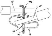
図1〜3は、横に並んで設けられる2つの小さい窓開口11及び12とこれらの小さい窓開口により下にある1つの大きい窓開口13とを持つ通電板10を示している。窓開口は、電気導体を接続するための締付け個所を規定する。締付け個所は、窓開口11,12,13の上縁11a,12a,13aとばね帯材料18の末端14,15,16,17との間に形成されている。 1 to 3 show a current-carrying
締付け個所を形成する窓開口の縁11a,12a,13aは、通電板10の実質的に平らな面から助走斜面の形に突出せしめられて、これらの縁に面するばね帯材料18の末端14,15,16の面範囲と共に、電気導体19,20の接続のための進入ホッパをそれぞれ形成している。 The
ばね帯材料18は、偏平なばね鋼板から1片で製造され、板ばね端部の形に構成される末端14,15,16,17を持っている。ばね帯材料18は、窓開口13に通され、その中間部分を窓開口12,13の下縁に位置固定されて、ばね帯材料18の外側にある縁が、窓開口の特別に形成された縁凹所21へ圧力ばねで圧入されている。これは、窓開口13内にあるばね帯材料18の位置固定の1つの実施例にすぎない。例えば窓開口の縁材料の係止又はかしめにより、位置固定の別のやり方も同様に可能である。ばね帯材料18の位置を固定される中間部分が窓開口13を通る面は、図示した実施例では通電板10の基準面を規定する。 The
特に図1から、新しい端子の重要な利点が分かる。通電板10の短い垂直範囲は、締付け個所の間の短い通電路を保証する。ばね帯材料18は、通電板10の両側から出て末端14,15,16,17に終わるばね腕(ばね湾曲部)により、機能を利用されない不要な構造間隔を通過せず、機能に完全に合わされて、その本来の役割のため、即ちそれぞれの締付け個所へ導入される電気導体へ締付け力を加える役割のためにのみ用いられる。その結果全体として、僅かな全高しか持たない新しい端子の非常にこじんまりした構造が生じる。 In particular, FIG. 1 shows an important advantage of the new terminal. The short vertical extent of the
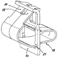
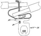
図4及び5は、本発明による端子の第2の実施例を示している。この端子は、図1〜3の実施例について説明したすべての特徴を持っているが、請求項4に従って、ばね帯材料18の位置を固定される中間部分から、弾性舌片22が付加的に形成されて、基準面の下にあって上方へU字状に開く凹所23へ入り込んでいる。弾性舌片22は、凹所23の下縁24と共に、付加的な締付け接続部を形成している。 4 and 5 show a second embodiment of the terminal according to the invention. This terminal has all the features described for the embodiment of FIGS. 1-3, but according to claim 4, an additional
この付加的な締付け接続部は、図5による実施例では、新しい端子をPE接続端子として使用する場合、必要な付加的なPE接続接触子26の差込み接触子25を差込むのに用いられる。 This additional clamping connection is used in the embodiment according to FIG. 5 to plug in the required plug-in
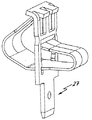
図6には、新しい端子が、通電板10の下端に、例えば電気器具の差込みブシュへ直接差込むことができる差込み片27を持つことができることを、示している。 FIG. 6 shows that the new terminal can have a
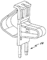
図7は、図6に存在する差込み片が2つのろう付け接続ピン28に代えられている。新しい端子の実施例を示している。 FIG. 7 shows that the insert present in FIG. 6 has been replaced by two
10 通電板
11,12,13 開口
14,15,16,17 末端
18 ばね帯材料
19,20 電気導体DESCRIPTION OF
Claims (5)
実質的に平らに延びかつ窓開口(11,12,13)を持つ剛性の通電する板(以下通電板10と称する)と、
ばね鋼板製の扁平な帯材料から1片で形成される締付けばね差込み片(以下ばね帯材料18と称する)とを有し、
ばね帯材料(18)が、通電板(10)に対して横向きに延びる中間部分を、通電板(10)の窓開口(13)に通され、この窓開口(13)において位置を固定され、
ばね帯材料(18)が、板ばね端部の形の少なくとも2つの末端(14,15,16,17)を持ち、これらの末端が、通電板(10)の互いに反対の側で、ばね帯材料(18)の位置固定された中間部分からそれぞれ始まって、窓開口(11,12,13)の1つへ入り込み、窓開口と共に電気導体(19,20)を接続するための締付け個所を形成している
ものにおいて、
ばね帯材料(18)の位置を固定される中間部分が、通電板(10)に対して横向きに延びる通電板(10)の基準面に位置せしめられ、
通電板(10)の窓開口(11,12,13)が基準面より上にあるように、基準面が窓開口より下に設けられている
ことを特徴とする、端子。A connection terminal for an electric conductor,
A rigid current-carrying plate (hereinafter referred to as a current-carrying plate 10) that extends substantially flat and has window openings (11, 12, 13);
A fastening spring insertion piece (hereinafter, referred to as a spring band material 18) formed of one piece from a flat band material made of a spring steel plate;
A spring strip material (18) is passed through a window opening (13) of the current-carrying plate (10) through an intermediate portion extending transversely to the current-carrying plate (10), and fixed in position in this window opening (13);
The spring band material (18) has at least two ends (14, 15, 16, 17) in the form of leaf spring ends, these ends being located on opposite sides of the current-carrying plate (10). Starting in each case from a fixed intermediate part of the material (18), it enters one of the window openings (11, 12, 13) and together with the window openings forms a clamping point for connecting electrical conductors (19, 20). In what you do
An intermediate portion in which the position of the spring band material (18) is fixed is positioned on a reference plane of the current-carrying plate (10) extending transversely to the current-carrying plate (10);
A terminal characterized in that the reference plane is provided below the window opening such that the window openings (11, 12, 13) of the current-carrying plate (10) are above the reference plane.
Applications Claiming Priority (1)
| Application Number | Priority Date | Filing Date | Title |
|---|---|---|---|
| DE10261536A DE10261536B4 (en) | 2002-12-23 | 2002-12-23 | Connection and connection terminal for electrical conductors |
Publications (2)
| Publication Number | Publication Date |
|---|---|
| JP2004207247A true JP2004207247A (en) | 2004-07-22 |
| JP4389246B2 JP4389246B2 (en) | 2009-12-24 |
Family
ID=32404359
Family Applications (1)
| Application Number | Title | Priority Date | Filing Date |
|---|---|---|---|
| JP2003436402A Expired - Fee Related JP4389246B2 (en) | 2002-12-23 | 2003-12-11 | Connection terminal for electrical conductor |
Country Status (5)
| Country | Link |
|---|---|
| EP (1) | EP1434307A1 (en) |
| JP (1) | JP4389246B2 (en) |
| DE (1) | DE10261536B4 (en) |
| PL (1) | PL364197A1 (en) |
| TW (1) | TWI278155B (en) |
Families Citing this family (13)
| Publication number | Priority date | Publication date | Assignee | Title |
|---|---|---|---|---|
| DE102004008447A1 (en) * | 2004-02-19 | 2005-09-08 | Abb Patent Gmbh | Spring-resistance binder for connecting electric conductors (EC) has a contact mounting (CM) to clamp an EC against the CM by means of a binder spring stretching in an arc across the CM |
| ES2246169B2 (en) * | 2004-07-28 | 2006-08-01 | I Division Electrica, S.A. | BIDIRECTIONAL CONNECTION TERMINAL WITHOUT SCREWS. |
| DE102004044889B4 (en) * | 2004-09-14 | 2011-06-30 | WAGO Verwaltungsgesellschaft mbH, 32423 | Electric floor terminal |
| DE102006049773B4 (en) | 2006-10-21 | 2009-01-08 | Abb Ag | Modular installation switching device |
| PT105364A (en) * | 2010-11-03 | 2012-05-03 | Efapel Empresa Fabril De Produtos Electricos S A | QUICK SPRING CONNECTION SYSTEM FOR ELECTRICAL CONTACTS |
| DE202011052337U1 (en) * | 2011-12-16 | 2013-03-21 | Weidmüller Interface GmbH & Co. KG | Plug arrangement of a series connection terminal |
| DE202011052272U1 (en) * | 2011-12-12 | 2013-03-13 | Weidmüller Interface GmbH & Co. KG | Plug arrangement of a series connection terminal |
| DE102011056410B4 (en) | 2011-12-14 | 2013-06-27 | Wago Verwaltungsgesellschaft Mbh | terminal |
| CN102969582A (en) * | 2012-11-14 | 2013-03-13 | 江门市创艺电器有限公司 | Pressing type lead wire connector |
| DE102015107853B4 (en) * | 2015-05-19 | 2020-08-13 | Wago Verwaltungsgesellschaft Mbh | Conductor connection terminal |
| DE102018117508B4 (en) | 2018-07-19 | 2024-01-18 | Wago Verwaltungsgesellschaft Mbh | Conductor connection terminal |
| DE102018130533B3 (en) * | 2018-11-30 | 2020-02-13 | Wago Verwaltungsgesellschaft Mbh | connecting element |
| DE102021132452B3 (en) | 2021-12-09 | 2022-12-15 | Bjb Gmbh & Co. Kg | connector |
Family Cites Families (7)
| Publication number | Priority date | Publication date | Assignee | Title |
|---|---|---|---|---|
| DE7734602U1 (en) * | 1977-11-11 | 1978-04-20 | Wago-Kontakttechnik Gmbh, 4950 Minden | Terminal with at least one clamping point for inserting electrical connection lugs |
| DE3743409C2 (en) * | 1987-12-21 | 1994-10-06 | Electro Terminal Gmbh | Screwless connection clamp |
| DE8907151U1 (en) * | 1989-06-10 | 1989-08-10 | Wilhelm Rutenbeck Gmbh & Co, 5885 Schalksmuehle, De | |
| DE19710306C2 (en) * | 1997-02-26 | 2001-12-06 | Wago Verwaltungs Gmbh | Electrical clamp |
| DE19855050A1 (en) * | 1998-11-28 | 2000-05-31 | Wuerth Adolf Gmbh & Co Kg | Plug-in terminal |
| EP1124286B1 (en) * | 2000-02-10 | 2002-12-11 | Hager Electro S.A. | Disconnectable terminal block for a modular electrical apparatus |
| DE20210105U1 (en) * | 2002-06-29 | 2002-10-02 | Wago Verwaltungs Gmbh | Electrical connection for terminals, connectors or devices |
-
2002
- 2002-12-23 DE DE10261536A patent/DE10261536B4/en not_active Expired - Fee Related
-
2003
- 2003-12-10 EP EP03028356A patent/EP1434307A1/en not_active Withdrawn
- 2003-12-11 JP JP2003436402A patent/JP4389246B2/en not_active Expired - Fee Related
- 2003-12-12 TW TW092135106A patent/TWI278155B/en not_active IP Right Cessation
- 2003-12-22 PL PL03364197A patent/PL364197A1/en not_active Application Discontinuation
Also Published As
| Publication number | Publication date |
|---|---|
| PL364197A1 (en) | 2004-06-28 |
| DE10261536B4 (en) | 2009-12-10 |
| EP1434307A1 (en) | 2004-06-30 |
| JP4389246B2 (en) | 2009-12-24 |
| TWI278155B (en) | 2007-04-01 |
| DE10261536A1 (en) | 2004-07-01 |
| TW200427157A (en) | 2004-12-01 |
Similar Documents
| Publication | Publication Date | Title |
|---|---|---|
| JP2704510B2 (en) | Electrical connectors for mounting printed circuit boards | |
| US7052320B2 (en) | Electrical connector having shielding plates | |
| JP2004207247A (en) | Connecting terminal for electric conductors | |
| JP2000268905A (en) | Printed wiring board connector | |
| WO2011150072A2 (en) | Electronic card connector | |
| US7115005B2 (en) | Electrical connector having resilient contacts | |
| JP2009520325A (en) | Electrical connector assembly and manufacturing method thereof | |
| JPH10189175A (en) | Electric connector | |
| US7931493B2 (en) | Cable assembly with a firm connection between a plurality of wires and a connector | |
| KR19980702909A (en) | Electrical Receptacle Assembly and Spring Contact therefor | |
| US4331376A (en) | Electric connectors | |
| US3317888A (en) | Bi-metal circuit board connector | |
| JP3676636B2 (en) | Interlayer connection structure | |
| JP2002025674A (en) | Connection terminal | |
| KR200407670Y1 (en) | Terminal mounting structure for wire-type board | |
| US20010051473A1 (en) | Connector | |
| JPH1126048A (en) | Terminal tool | |
| KR100502700B1 (en) | electricity connector | |
| CN217064149U (en) | Fastening device and arrangement for fastening a connection arrangement on a printed circuit board | |
| JP3276890B2 (en) | connector | |
| JPH0119338Y2 (en) | ||
| KR200324360Y1 (en) | electricity connector | |
| KR20160042239A (en) | Wire terminal | |
| JP3637409B2 (en) | Sensor base | |
| JP4229222B2 (en) | Taping connection terminal |
Legal Events
| Date | Code | Title | Description |
|---|---|---|---|
| A621 | Written request for application examination |
Free format text: JAPANESE INTERMEDIATE CODE: A621 Effective date: 20061003 |
|
| A131 | Notification of reasons for refusal |
Free format text: JAPANESE INTERMEDIATE CODE: A131 Effective date: 20090106 |
|
| A521 | Request for written amendment filed |
Free format text: JAPANESE INTERMEDIATE CODE: A523 Effective date: 20090402 |
|
| A131 | Notification of reasons for refusal |
Free format text: JAPANESE INTERMEDIATE CODE: A131 Effective date: 20090616 |
|
| A521 | Request for written amendment filed |
Free format text: JAPANESE INTERMEDIATE CODE: A523 Effective date: 20090702 |
|
| TRDD | Decision of grant or rejection written | ||
| A01 | Written decision to grant a patent or to grant a registration (utility model) |
Free format text: JAPANESE INTERMEDIATE CODE: A01 Effective date: 20090915 |
|
| A01 | Written decision to grant a patent or to grant a registration (utility model) |
Free format text: JAPANESE INTERMEDIATE CODE: A01 |
|
| A61 | First payment of annual fees (during grant procedure) |
Free format text: JAPANESE INTERMEDIATE CODE: A61 Effective date: 20090925 |
|
| FPAY | Renewal fee payment (event date is renewal date of database) |
Free format text: PAYMENT UNTIL: 20121016 Year of fee payment: 3 |
|
| R150 | Certificate of patent or registration of utility model |
Free format text: JAPANESE INTERMEDIATE CODE: R150 |
|
| FPAY | Renewal fee payment (event date is renewal date of database) |
Free format text: PAYMENT UNTIL: 20131016 Year of fee payment: 4 |
|
| R250 | Receipt of annual fees |
Free format text: JAPANESE INTERMEDIATE CODE: R250 |
|
| R250 | Receipt of annual fees |
Free format text: JAPANESE INTERMEDIATE CODE: R250 |
|
| R250 | Receipt of annual fees |
Free format text: JAPANESE INTERMEDIATE CODE: R250 |
|
| R250 | Receipt of annual fees |
Free format text: JAPANESE INTERMEDIATE CODE: R250 |
|
| LAPS | Cancellation because of no payment of annual fees |