JP2004202249A - Talar component - Google Patents
Talar component Download PDFInfo
- Publication number
- JP2004202249A JP2004202249A JP2003425332A JP2003425332A JP2004202249A JP 2004202249 A JP2004202249 A JP 2004202249A JP 2003425332 A JP2003425332 A JP 2003425332A JP 2003425332 A JP2003425332 A JP 2003425332A JP 2004202249 A JP2004202249 A JP 2004202249A
- Authority
- JP
- Japan
- Prior art keywords
- assembly
- tibial
- ankle
- tibial device
- calcaneal
- Prior art date
- Legal status (The legal status is an assumption and is not a legal conclusion. Google has not performed a legal analysis and makes no representation as to the accuracy of the status listed.)
- Granted
Links
Images


Classifications
-
- A—HUMAN NECESSITIES
- A61—MEDICAL OR VETERINARY SCIENCE; HYGIENE
- A61F—FILTERS IMPLANTABLE INTO BLOOD VESSELS; PROSTHESES; DEVICES PROVIDING PATENCY TO, OR PREVENTING COLLAPSING OF, TUBULAR STRUCTURES OF THE BODY, e.g. STENTS; ORTHOPAEDIC, NURSING OR CONTRACEPTIVE DEVICES; FOMENTATION; TREATMENT OR PROTECTION OF EYES OR EARS; BANDAGES, DRESSINGS OR ABSORBENT PADS; FIRST-AID KITS
- A61F2/00—Filters implantable into blood vessels; Prostheses, i.e. artificial substitutes or replacements for parts of the body; Appliances for connecting them with the body; Devices providing patency to, or preventing collapsing of, tubular structures of the body, e.g. stents
- A61F2/02—Prostheses implantable into the body
- A61F2/30—Joints
- A61F2/42—Joints for wrists or ankles; for hands, e.g. fingers; for feet, e.g. toes
- A61F2/4202—Joints for wrists or ankles; for hands, e.g. fingers; for feet, e.g. toes for ankles
-
- A—HUMAN NECESSITIES
- A61—MEDICAL OR VETERINARY SCIENCE; HYGIENE
- A61F—FILTERS IMPLANTABLE INTO BLOOD VESSELS; PROSTHESES; DEVICES PROVIDING PATENCY TO, OR PREVENTING COLLAPSING OF, TUBULAR STRUCTURES OF THE BODY, e.g. STENTS; ORTHOPAEDIC, NURSING OR CONTRACEPTIVE DEVICES; FOMENTATION; TREATMENT OR PROTECTION OF EYES OR EARS; BANDAGES, DRESSINGS OR ABSORBENT PADS; FIRST-AID KITS
- A61F2/00—Filters implantable into blood vessels; Prostheses, i.e. artificial substitutes or replacements for parts of the body; Appliances for connecting them with the body; Devices providing patency to, or preventing collapsing of, tubular structures of the body, e.g. stents
- A61F2/02—Prostheses implantable into the body
- A61F2/30—Joints
- A61F2/30767—Special external or bone-contacting surface, e.g. coating for improving bone ingrowth
-
- A—HUMAN NECESSITIES
- A61—MEDICAL OR VETERINARY SCIENCE; HYGIENE
- A61F—FILTERS IMPLANTABLE INTO BLOOD VESSELS; PROSTHESES; DEVICES PROVIDING PATENCY TO, OR PREVENTING COLLAPSING OF, TUBULAR STRUCTURES OF THE BODY, e.g. STENTS; ORTHOPAEDIC, NURSING OR CONTRACEPTIVE DEVICES; FOMENTATION; TREATMENT OR PROTECTION OF EYES OR EARS; BANDAGES, DRESSINGS OR ABSORBENT PADS; FIRST-AID KITS
- A61F2/00—Filters implantable into blood vessels; Prostheses, i.e. artificial substitutes or replacements for parts of the body; Appliances for connecting them with the body; Devices providing patency to, or preventing collapsing of, tubular structures of the body, e.g. stents
- A61F2/02—Prostheses implantable into the body
- A61F2/30—Joints
- A61F2002/30001—Additional features of subject-matter classified in A61F2/28, A61F2/30 and subgroups thereof
- A61F2002/30316—The prosthesis having different structural features at different locations within the same prosthesis; Connections between prosthetic parts; Special structural features of bone or joint prostheses not otherwise provided for
- A61F2002/30329—Connections or couplings between prosthetic parts, e.g. between modular parts; Connecting elements
- A61F2002/30331—Connections or couplings between prosthetic parts, e.g. between modular parts; Connecting elements made by longitudinally pushing a protrusion into a complementarily-shaped recess, e.g. held by friction fit
- A61F2002/30362—Connections or couplings between prosthetic parts, e.g. between modular parts; Connecting elements made by longitudinally pushing a protrusion into a complementarily-shaped recess, e.g. held by friction fit with possibility of relative movement between the protrusion and the recess
- A61F2002/30364—Rotation about the common longitudinal axis
-
- A—HUMAN NECESSITIES
- A61—MEDICAL OR VETERINARY SCIENCE; HYGIENE
- A61F—FILTERS IMPLANTABLE INTO BLOOD VESSELS; PROSTHESES; DEVICES PROVIDING PATENCY TO, OR PREVENTING COLLAPSING OF, TUBULAR STRUCTURES OF THE BODY, e.g. STENTS; ORTHOPAEDIC, NURSING OR CONTRACEPTIVE DEVICES; FOMENTATION; TREATMENT OR PROTECTION OF EYES OR EARS; BANDAGES, DRESSINGS OR ABSORBENT PADS; FIRST-AID KITS
- A61F2/00—Filters implantable into blood vessels; Prostheses, i.e. artificial substitutes or replacements for parts of the body; Appliances for connecting them with the body; Devices providing patency to, or preventing collapsing of, tubular structures of the body, e.g. stents
- A61F2/02—Prostheses implantable into the body
- A61F2/30—Joints
- A61F2002/30001—Additional features of subject-matter classified in A61F2/28, A61F2/30 and subgroups thereof
- A61F2002/30316—The prosthesis having different structural features at different locations within the same prosthesis; Connections between prosthetic parts; Special structural features of bone or joint prostheses not otherwise provided for
- A61F2002/30329—Connections or couplings between prosthetic parts, e.g. between modular parts; Connecting elements
- A61F2002/30331—Connections or couplings between prosthetic parts, e.g. between modular parts; Connecting elements made by longitudinally pushing a protrusion into a complementarily-shaped recess, e.g. held by friction fit
- A61F2002/30362—Connections or couplings between prosthetic parts, e.g. between modular parts; Connecting elements made by longitudinally pushing a protrusion into a complementarily-shaped recess, e.g. held by friction fit with possibility of relative movement between the protrusion and the recess
- A61F2002/30369—Limited lateral translation of the protrusion within a larger recess
-
- A—HUMAN NECESSITIES
- A61—MEDICAL OR VETERINARY SCIENCE; HYGIENE
- A61F—FILTERS IMPLANTABLE INTO BLOOD VESSELS; PROSTHESES; DEVICES PROVIDING PATENCY TO, OR PREVENTING COLLAPSING OF, TUBULAR STRUCTURES OF THE BODY, e.g. STENTS; ORTHOPAEDIC, NURSING OR CONTRACEPTIVE DEVICES; FOMENTATION; TREATMENT OR PROTECTION OF EYES OR EARS; BANDAGES, DRESSINGS OR ABSORBENT PADS; FIRST-AID KITS
- A61F2/00—Filters implantable into blood vessels; Prostheses, i.e. artificial substitutes or replacements for parts of the body; Appliances for connecting them with the body; Devices providing patency to, or preventing collapsing of, tubular structures of the body, e.g. stents
- A61F2/02—Prostheses implantable into the body
- A61F2/30—Joints
- A61F2002/30001—Additional features of subject-matter classified in A61F2/28, A61F2/30 and subgroups thereof
- A61F2002/30316—The prosthesis having different structural features at different locations within the same prosthesis; Connections between prosthetic parts; Special structural features of bone or joint prostheses not otherwise provided for
- A61F2002/30535—Special structural features of bone or joint prostheses not otherwise provided for
- A61F2002/30604—Special structural features of bone or joint prostheses not otherwise provided for modular
- A61F2002/30616—Sets comprising a plurality of prosthetic parts of different sizes or orientations
-
- A—HUMAN NECESSITIES
- A61—MEDICAL OR VETERINARY SCIENCE; HYGIENE
- A61F—FILTERS IMPLANTABLE INTO BLOOD VESSELS; PROSTHESES; DEVICES PROVIDING PATENCY TO, OR PREVENTING COLLAPSING OF, TUBULAR STRUCTURES OF THE BODY, e.g. STENTS; ORTHOPAEDIC, NURSING OR CONTRACEPTIVE DEVICES; FOMENTATION; TREATMENT OR PROTECTION OF EYES OR EARS; BANDAGES, DRESSINGS OR ABSORBENT PADS; FIRST-AID KITS
- A61F2/00—Filters implantable into blood vessels; Prostheses, i.e. artificial substitutes or replacements for parts of the body; Appliances for connecting them with the body; Devices providing patency to, or preventing collapsing of, tubular structures of the body, e.g. stents
- A61F2/02—Prostheses implantable into the body
- A61F2/30—Joints
- A61F2002/30001—Additional features of subject-matter classified in A61F2/28, A61F2/30 and subgroups thereof
- A61F2002/30621—Features concerning the anatomical functioning or articulation of the prosthetic joint
- A61F2002/30649—Ball-and-socket joints
-
- A—HUMAN NECESSITIES
- A61—MEDICAL OR VETERINARY SCIENCE; HYGIENE
- A61F—FILTERS IMPLANTABLE INTO BLOOD VESSELS; PROSTHESES; DEVICES PROVIDING PATENCY TO, OR PREVENTING COLLAPSING OF, TUBULAR STRUCTURES OF THE BODY, e.g. STENTS; ORTHOPAEDIC, NURSING OR CONTRACEPTIVE DEVICES; FOMENTATION; TREATMENT OR PROTECTION OF EYES OR EARS; BANDAGES, DRESSINGS OR ABSORBENT PADS; FIRST-AID KITS
- A61F2/00—Filters implantable into blood vessels; Prostheses, i.e. artificial substitutes or replacements for parts of the body; Appliances for connecting them with the body; Devices providing patency to, or preventing collapsing of, tubular structures of the body, e.g. stents
- A61F2/02—Prostheses implantable into the body
- A61F2/30—Joints
- A61F2/30767—Special external or bone-contacting surface, e.g. coating for improving bone ingrowth
- A61F2/30771—Special external or bone-contacting surface, e.g. coating for improving bone ingrowth applied in original prostheses, e.g. holes or grooves
- A61F2002/30878—Special external or bone-contacting surface, e.g. coating for improving bone ingrowth applied in original prostheses, e.g. holes or grooves with non-sharp protrusions, for instance contacting the bone for anchoring, e.g. keels, pegs, pins, posts, shanks, stems, struts
- A61F2002/30884—Fins or wings, e.g. longitudinal wings for preventing rotation within the bone cavity
-
- A—HUMAN NECESSITIES
- A61—MEDICAL OR VETERINARY SCIENCE; HYGIENE
- A61F—FILTERS IMPLANTABLE INTO BLOOD VESSELS; PROSTHESES; DEVICES PROVIDING PATENCY TO, OR PREVENTING COLLAPSING OF, TUBULAR STRUCTURES OF THE BODY, e.g. STENTS; ORTHOPAEDIC, NURSING OR CONTRACEPTIVE DEVICES; FOMENTATION; TREATMENT OR PROTECTION OF EYES OR EARS; BANDAGES, DRESSINGS OR ABSORBENT PADS; FIRST-AID KITS
- A61F2/00—Filters implantable into blood vessels; Prostheses, i.e. artificial substitutes or replacements for parts of the body; Appliances for connecting them with the body; Devices providing patency to, or preventing collapsing of, tubular structures of the body, e.g. stents
- A61F2/02—Prostheses implantable into the body
- A61F2/30—Joints
- A61F2/42—Joints for wrists or ankles; for hands, e.g. fingers; for feet, e.g. toes
- A61F2/4202—Joints for wrists or ankles; for hands, e.g. fingers; for feet, e.g. toes for ankles
- A61F2002/4205—Tibial components
-
- A—HUMAN NECESSITIES
- A61—MEDICAL OR VETERINARY SCIENCE; HYGIENE
- A61F—FILTERS IMPLANTABLE INTO BLOOD VESSELS; PROSTHESES; DEVICES PROVIDING PATENCY TO, OR PREVENTING COLLAPSING OF, TUBULAR STRUCTURES OF THE BODY, e.g. STENTS; ORTHOPAEDIC, NURSING OR CONTRACEPTIVE DEVICES; FOMENTATION; TREATMENT OR PROTECTION OF EYES OR EARS; BANDAGES, DRESSINGS OR ABSORBENT PADS; FIRST-AID KITS
- A61F2/00—Filters implantable into blood vessels; Prostheses, i.e. artificial substitutes or replacements for parts of the body; Appliances for connecting them with the body; Devices providing patency to, or preventing collapsing of, tubular structures of the body, e.g. stents
- A61F2/02—Prostheses implantable into the body
- A61F2/30—Joints
- A61F2/42—Joints for wrists or ankles; for hands, e.g. fingers; for feet, e.g. toes
- A61F2/4202—Joints for wrists or ankles; for hands, e.g. fingers; for feet, e.g. toes for ankles
- A61F2002/4207—Talar components
-
- A—HUMAN NECESSITIES
- A61—MEDICAL OR VETERINARY SCIENCE; HYGIENE
- A61F—FILTERS IMPLANTABLE INTO BLOOD VESSELS; PROSTHESES; DEVICES PROVIDING PATENCY TO, OR PREVENTING COLLAPSING OF, TUBULAR STRUCTURES OF THE BODY, e.g. STENTS; ORTHOPAEDIC, NURSING OR CONTRACEPTIVE DEVICES; FOMENTATION; TREATMENT OR PROTECTION OF EYES OR EARS; BANDAGES, DRESSINGS OR ABSORBENT PADS; FIRST-AID KITS
- A61F2220/00—Fixations or connections for prostheses classified in groups A61F2/00 - A61F2/26 or A61F2/82 or A61F9/00 or A61F11/00 or subgroups thereof
- A61F2220/0025—Connections or couplings between prosthetic parts, e.g. between modular parts; Connecting elements
- A61F2220/0033—Connections or couplings between prosthetic parts, e.g. between modular parts; Connecting elements made by longitudinally pushing a protrusion into a complementary-shaped recess, e.g. held by friction fit
-
- A—HUMAN NECESSITIES
- A61—MEDICAL OR VETERINARY SCIENCE; HYGIENE
- A61F—FILTERS IMPLANTABLE INTO BLOOD VESSELS; PROSTHESES; DEVICES PROVIDING PATENCY TO, OR PREVENTING COLLAPSING OF, TUBULAR STRUCTURES OF THE BODY, e.g. STENTS; ORTHOPAEDIC, NURSING OR CONTRACEPTIVE DEVICES; FOMENTATION; TREATMENT OR PROTECTION OF EYES OR EARS; BANDAGES, DRESSINGS OR ABSORBENT PADS; FIRST-AID KITS
- A61F2310/00—Prostheses classified in A61F2/28 or A61F2/30 - A61F2/44 being constructed from or coated with a particular material
- A61F2310/00005—The prosthesis being constructed from a particular material
- A61F2310/00011—Metals or alloys
- A61F2310/00017—Iron- or Fe-based alloys, e.g. stainless steel
-
- A—HUMAN NECESSITIES
- A61—MEDICAL OR VETERINARY SCIENCE; HYGIENE
- A61F—FILTERS IMPLANTABLE INTO BLOOD VESSELS; PROSTHESES; DEVICES PROVIDING PATENCY TO, OR PREVENTING COLLAPSING OF, TUBULAR STRUCTURES OF THE BODY, e.g. STENTS; ORTHOPAEDIC, NURSING OR CONTRACEPTIVE DEVICES; FOMENTATION; TREATMENT OR PROTECTION OF EYES OR EARS; BANDAGES, DRESSINGS OR ABSORBENT PADS; FIRST-AID KITS
- A61F2310/00—Prostheses classified in A61F2/28 or A61F2/30 - A61F2/44 being constructed from or coated with a particular material
- A61F2310/00005—The prosthesis being constructed from a particular material
- A61F2310/00011—Metals or alloys
- A61F2310/00023—Titanium or titanium-based alloys, e.g. Ti-Ni alloys
-
- A—HUMAN NECESSITIES
- A61—MEDICAL OR VETERINARY SCIENCE; HYGIENE
- A61F—FILTERS IMPLANTABLE INTO BLOOD VESSELS; PROSTHESES; DEVICES PROVIDING PATENCY TO, OR PREVENTING COLLAPSING OF, TUBULAR STRUCTURES OF THE BODY, e.g. STENTS; ORTHOPAEDIC, NURSING OR CONTRACEPTIVE DEVICES; FOMENTATION; TREATMENT OR PROTECTION OF EYES OR EARS; BANDAGES, DRESSINGS OR ABSORBENT PADS; FIRST-AID KITS
- A61F2310/00—Prostheses classified in A61F2/28 or A61F2/30 - A61F2/44 being constructed from or coated with a particular material
- A61F2310/00005—The prosthesis being constructed from a particular material
- A61F2310/00011—Metals or alloys
- A61F2310/00029—Cobalt-based alloys, e.g. Co-Cr alloys or Vitallium
Abstract
Description
本発明は、関節又はその関節の一部分の置換のための人工関節システムに関する。特に、本発明は、骨量の減少又は深刻且つ回復不能な骨外傷を起こした四肢に使用することができる人工足関節システムに関する。 The present invention relates to an artificial joint system for replacement of a joint or a part of the joint. In particular, the present invention relates to an artificial ankle system that can be used on a limb that has lost bone mass or has severe and irreversible bone trauma.
変形性関節症や足関節の外傷等の足関節の様々な疾患の治療において、全足関節置換術又は「関節形成術」は急速に一般的な処置方法になってきている。患者の苦痛を取り除く1つの方法として、足関節の関節面、即ち脛骨下関節面及び距骨の関節面を置換することが挙げられる。脛骨下関節面は凹形のポリマーベアリングで置換され、距骨の関節面は凸形の金属ベアリングで置換される。使用されるポリマーは例えばポリエチレンでもよい。このような置換術では、痛みの軽減、運動の増加及び足関節の解剖学的復元が整形外科医の目的である。 In the treatment of various disorders of the ankle such as osteoarthritis and trauma to the ankle, total ankle replacement or "arthroplasty" is rapidly becoming a common treatment method. One way to relieve the patient's pain is to replace the articular surfaces of the ankle joint, ie, the subtibia and talus articular surfaces. The subtibia articular surface is replaced by a concave polymer bearing and the talar articular surface is replaced by a convex metal bearing. The polymer used may be, for example, polyethylene. In such replacement procedures, the aim of the orthopedic surgeon is to reduce pain, increase movement and anatomic reconstruction of the ankle joint.
2つの基本的なタイプの足関節置換手段がある。すなわち、非拘束式半月ベアリング形人工足関節と半拘束式固定ベアリング形人工足関節である。半拘束式固定ベアリング形人工足関節の例としては、デピュイ社のアジリティ・アンクル(Agility Ankle)が挙げられる。半拘束式固定ベアリング形人工足関節は1つの関節インタフェース、即ち凹形のポリマー支承面と凸形の金属支承面の間のインタフェースを有する。半拘束式人工関節では、凹形のポリマーベアリングは脛骨に対して固定される。さらに、凸形の金属ベアリング表面は距骨に対して固定される。したがって、半拘束式固定ベアリング形人工足関節は患者に限られた量の足関節の運動しか与えることができない。 There are two basic types of ankle replacement means. That is, an unconstrained semilunar bearing artificial ankle joint and a semi-constrained fixed bearing artificial ankle joint. An example of a semi-constrained fixed-bearing ankle prosthesis is Agility Ankle from DePuy. Semi-constrained fixed-bearing ankles have one joint interface, the interface between a concave polymer bearing surface and a convex metal bearing surface. In a semi-restrained joint, the concave polymer bearing is fixed relative to the tibia. Further, the convex metal bearing surface is fixed relative to the talus. Thus, a semi-constrained fixed-bearing ankle prosthesis can provide a patient with only a limited amount of ankle motion.
上記とは異なり、非拘束式半月ベアリング形人工足関節は、2つの関節インタフェースを有し、それにより自由度を増すことができる。一方の関節インタフェースは脛骨の構成部品と半月ベアリングの間に存在する。他方の関節インタフェースは上記半月ベアリングと踵骨の構成部品の間に存在する。非拘束式半月ベアリング形人工足関節の例としては、リンク社のS.T.A.R.プロステーシス(S.T.A.R. prosthesis)やエンドテック社のB−Pアンクル(B-P ankle)が挙げられ、両者とも足関節の前面から取り付ける。これら非拘束式人工足関節には様々な問題点があり、そのうちの幾つかをここに例として示す。第1に、足関節の安定性が悪いことが挙げられる。具体的には、半月ポリマーベアリングの位置がずれてしまう場合がある。第2に、非拘束式人工足関節は、過度に内反/外反のずれがある患者や、足の配列又は安定性に影響する軟組織が弱くなっている患者には使用することができない。第3に、線維組織はベアリングを被包しがちであり、その結果運動が制限される。第4に、骨の接触面積が小さいため、脛骨の構成部品が動いてしまうことが知られている。 Unlike the above, the unconstrained half-moon bearing prosthesis has two joint interfaces, which can increase the degree of freedom. One joint interface is between the tibial component and the meniscal bearing. The other joint interface is between the meniscal bearing and the calcaneal components. Examples of unconstrained half moon bearing artificial ankle joints include STAR prosthesis from Link Inc. and BP ankle from Endotech Inc., both of which are foot ankles. Attach from the front of the joint. There are various problems with these unconstrained ankle prostheses, some of which are given here as examples. First, the stability of the ankle joint is poor. Specifically, the position of the half moon polymer bearing may shift. Second, unconstrained ankle prostheses cannot be used in patients with excessive varus / valgus deviations or in patients with weak soft tissues that affect foot alignment or stability. Third, fibrous tissue tends to encapsulate the bearing, thereby limiting movement. Fourth, it is known that the tibia components move due to the small bone contact area.
したがって、半拘束式固定ベアリング形人工足関節よりも大きな運動の自由度を可能にすると共に非拘束式半月ベアリング形人工足関節の欠点を持たない人工足関節システムが必要とされている。 Accordingly, there is a need for a prosthetic ankle system that allows greater freedom of movement than a semi-constrained fixed-bearing ankle prosthesis and does not have the disadvantages of an unconstrained semi-circular bearing ankle prosthesis.
これら要望に取り組むため、本発明は、距骨に対して回動自在であり、それにより足関節に追加の自由度を与える踵骨コンポーネントを含む半拘束式人工足関節から成る。 To address these needs, the present invention comprises a semi-constrained ankle prosthesis that includes a calcaneal component that is pivotable with respect to the talus, thereby providing the ankle with additional degrees of freedom.
本発明は、一形態では、脛骨に取付け可能な脛骨装置を有する人工足関節を提供する。脛骨装置は、凹状関節面を有する。踵骨組立体が、脛骨装置の凹状関節面に係合するよう構成された凸状関節面を備えるドーム部分を有し、ドーム部分は、脛骨装置に対して回動できるようになっている。踵骨組立体は、距骨に取り付けられるようになったベース部分を更に有する。ベース部分は、ドーム部分に対して回動できる。 The present invention, in one aspect, provides an ankle prosthesis having a tibial device attachable to the tibia. The tibial device has a concave articulating surface. The calcaneus assembly has a dome portion with a convex articulation surface configured to engage a concave articulation surface of the tibial device, the dome portion being rotatable relative to the tibial device. The calcaneus assembly further includes a base portion adapted to be attached to the talus. The base portion is pivotable with respect to the dome portion.
本発明は、別の形態では、脛骨に取付け可能な脛骨装置を有する人工足関節を提供する。踵骨組立体が、脛骨装置に係合するよう構成されたドーム部分を有し、ドーム部分は、第1の平面内で脛骨装置に対して回動できるようになっている。踵骨組立体は、距骨に取り付けられるようになったベース部分を更に有する。ベース部分は、第1の平面に実質的に垂直な第1の平面内でドーム部分に対して回動できる。 The present invention, in another form, provides an ankle prosthesis having a tibial device attachable to the tibia. The calcaneus assembly has a dome portion configured to engage the tibial device, wherein the dome portion is rotatable relative to the tibial device in a first plane. The calcaneus assembly further includes a base portion adapted to be attached to the talus. The base portion is pivotable with respect to the dome portion in a first plane substantially perpendicular to the first plane.
本発明は、更に別の形態では、脛骨に取付け可能な脛骨装置を有する人工足関節を提供する。踵骨組立体が、脛骨装置に係合するよう構成された第1の部分を有し、第1の部分は、第1の平面内で脛骨装置に対して回動できるようになっている。第2の部分が、足の距骨に取り付けられる。第2の部分は、足の足底によって定められる第3の平面に実質的に平行な第2の平面内で第1の部分に対して回動できる。 The present invention, in yet another form, provides an ankle prosthesis having a tibial device attachable to the tibia. The calcaneus assembly has a first portion configured to engage the tibial device, the first portion being rotatable relative to the tibial device in a first plane. A second portion is attached to the talus of the foot. The second portion is pivotable relative to the first portion in a second plane substantially parallel to a third plane defined by the sole of the foot.
本発明の利点は、歩行サイクルにおける足関節の運動範囲が増大することにある。 An advantage of the present invention is that the range of motion of the ankle during the walking cycle is increased.
別の利点は、踵骨コンポーネントが脛骨コンポーネントの下及び内部で動くことができることにより、足関節全体に加わる応力を減少させることによってインプラントの寿命が長くなるということにある。 Another advantage resides in the ability of the calcaneal component to move under and within the tibial component, thereby extending the life of the implant by reducing the stress on the entire ankle joint.
さらに別の利点は、凹状ポリマーベアリングの摩耗が最小限に抑えられるということにある。 Yet another advantage resides in that wear of the concave polymer bearing is minimized.
図中、同一の参照符号は対応関係にある部分を示すものとする。 In the drawings, the same reference numerals indicate corresponding parts.
本発明の原理をより深く理解するために、図面に示された実施形態を参照し、以下に説明する。この説明により本発明の範囲が限定されるものではないことは理解されるべきであろう。また、本発明は、図示された実施形態に対するあらゆる変更例や修正例を含むと共に、当業者であれば通常思いつくような本発明の原理の別の応用例をも含むことは理解されるべきであろう。 BRIEF DESCRIPTION OF THE DRAWINGS For a better understanding of the principles of the present invention, reference will now be made to the embodiments illustrated in the drawings. It should be understood that the description is not intended to limit the scope of the invention. It should also be understood that the present invention includes all changes and modifications to the illustrated embodiment, as well as other applications of the principles of the present invention, which would normally occur to one skilled in the art. There will be.
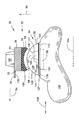
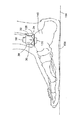
図1を参照すると、本発明の一実施形態が示されている。特に、人工足関節が全体として符号30で示されている。人工足関節30は右足関節用である。左足関節用の人工足関節は人工足関節30の鏡像である。人工足関節30は、患者の足関節が置換される関節置換術向きに構成されたものである。人工足関節30は、踵骨組立体又はコンポーネント34及び脛骨組立体又はコンポーネント32の形態をした脛骨装置を含む。脛骨組立体32と踵骨組立体34は脛骨に対して距骨が屈曲及び伸展するように相互に作用する。本発明の一特徴によれば、脛骨組立体32と踵骨組立体34は又、正常な足関節と同様に、屈曲平面及び伸展平面に垂直な平面内で脛骨に対して距骨が回動できるよう相互に作用する。人工足関節30は、患者の骨と組織の除去を最小限に抑えるためにコンパクトになっている。
Referring to FIG. 1, one embodiment of the present invention is shown. In particular, the artificial ankle joint is indicated generally by the
脛骨組立体32は、脛骨コンポーネント38に嵌まり込み、これによって保持されているベアリングコンポーネント36を含む。脛骨コンポーネント38は、内側縁部42及び外側縁部44を持つベースプレート又は上壁40を有する。内側壁46及び外側壁48を有する位置決め壁がそれぞれ、内側縁部42及び外側縁部44から、上下方向50に延びている。三角形の延長部56が上壁40の後方縁部52(図2)から、前後方向54に延びている。脛骨フィン58の形態をした突起が、上壁40から下上方向60に延びている。
ベアリングコンポーネント36はポリマー又はプラスチックのような弾性材料から形成される。特に、ベアリングコンポーネント36はポリエチレンから形成される。ベアリングコンポーネント36は、踵骨組立体34とインタフェースをとる凹状関節面96を有する。凹状関節面96は上下方向50に向いている。凹状関節面96は前方側部98から後方側部100へ向かって円弧を形成し、表面96の断面は内−外軸線102に沿って一定である。ベアリングコンポーネント36の内側側部114と外側側部120は各々、内側壁46と外側壁48に近接している。
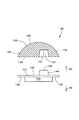
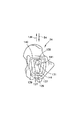
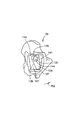
踵骨組立体34は、図3に最もよく示されているように、上方部分又はドーム部分126及び下方部分又はベース部分127を含む。ドーム部分126は弓状湾曲表面128の形態をした凸状関節面を有する。湾曲表面128はドーム部分126の前方端部135から後方端部137の間の円弧に沿って延びている。図4に最もよく示されているように、ドーム部分126は、その円弧に沿って前後方向54にテーパしている。すなわち、ドーム部分126は、後方端部137から前方端部135へ向かって僅かに外方に傾斜した内側側部139と外側側部141を有する。ドーム部分126の平らな底面130は、その中に切頭円錐形凹み131を有する。図示の実施形態では、凹み131は、後方端部137よりもドーム部分126の前方端部135に近いところに位置している。
The
ベース部分127は、図5に最もよく示されている上側側部140及び下側表面142を備えたプレート138を有する。上側表面140の上には、凹み131の中に嵌まる大きさの切頭円錐形の突起144が、下上方向60に沿って延びている。図2に示すように、突起144の上側側部149と凹み131の輪郭を定める下側表面151の間には隙間147がある。しかしながら、突起144の上側側部149は又、下側表面151に接触するか又は下側表面151に隣接してもよい。下側側部142上には踵骨フィンの形態をした突起132が、上下方向50に延びている。踵骨フィン132は患者の足の距骨145内へ埋め込まれる。
The
踵骨組立体34のテーパしたドーム部分126は、脛骨ベアリングコンポーネント36と相補関係をなして嵌合している。ベアリングコンポーネント36の凹状表面96はドーム部分126に嵌着している。ベアリングコンポーネント36の側部114,120は各々、ドーム部分126の側部139,141に係合している。ドーム部分126は脛骨装置32に対して回動しながら摺動する。特に、ドーム部分126は内−外軸線102に垂直な表面内でベアリングコンポーネント36に対して回動しながら摺動する。このようにして、ドーム部分126と脛骨組立体32の間の相対的な回動運動が可能となる。ベアリングコンポーネント36とドーム部分126は図6に示すように、伸展位置146と屈曲位置148の間で約60°の運動範囲をもたらす。
The tapered
再び図1を参照すると、ベアリングコンポーネント36の側部114,120と脛骨コンポーネント38の壁46,48は、あらゆる位置で側方に滑らないようにドーム部分126を保持している。壁46,48は関節を支持し、人工足関節30がいつでも正しい位置を保ったままであるようにしている。図4に最もよく示されているように、ドーム部分126は、後前方向136に僅かに幅が広くなっている。したがって、幅の広い端部135は、構造健全性を損なうことなく幅の狭い端部137よりも良好に凹み131に対応することができる。側部114,120の間の距離も又同様に広がっており、脛骨組立体32とドーム部分126を整列した状態に保っている。人工足関節30は、ドーム部分126とベアリングコンポーネント36が合致するところで回動し、屈曲及び伸展ができるようになっている。表面96,128は、互いに対して摺動して回動が生じるのを可能にし、それにより、生まれつき備わった足関節と同様の動き及び運動範囲をもつことができる。
Referring again to FIG. 1, the
本発明の特徴によれば、ドーム部分126はベース部分127に対して回動可能であり、それによって、ベアリングコンポーネント36とドーム部分126の間の回動により得られる屈曲及び伸展に加えて、患者の足関節に自由度を与えることができる。さらに、図7及び図8に示すように、ドーム部分126はベース部分127に対して矢印150,152で示された方向に回動可能である。したがって、ドーム部分126とベース部分127の間の相対的な回動運動が可能になる。方向150,152における回動面は、図6に示される屈曲及び伸展面に対して垂直である。方向150,152における回動面は、内−外軸線102に平行である。さらに、方向150,152における回動面は、図2に最もよく示されているように、右足の足底156(図9)によって定められる平面154に実質的に平行である。方向150,152における回動面は、平面154に対して約20°の角度に差し向けることも又可能である。
According to a feature of the invention, the
ベース部分127の突起144は、ドーム部分126の凹み131内で回転可能であり、それによって回動が可能になる。ドーム部分126の下側側部130とプレート138の上側側部140は、これら側部130,140相互間にある隙間160を最小化してその間の相対的な回転も可能にするための凹み131と突起144を除けば、共に平らである。下側側部130と上側側部140は共に方向150,152における回動面に平行である。方向150,152におけるドーム部分126の回動範囲は、約30°であり、腓骨と脛骨、足関節の骨及び足の骨を結合する靭帯の引張具合や張り具合によって制限される。凹み131に受け入れられている突起144によって、内−外軸線102及び前−後軸線158の両方におけるドーム部分126とベース部分127の相対的な運動は阻止される。
The
脛骨コンポーネント38は、図10に示すように脛骨と腓骨の間の領域を橋渡しできるほど幅広くなければならない。埋め込むときには、内側壁46を内踝に対して突き合わせた状態で外側壁48を腓骨に対して突き合わせる。このようにして、腓骨は脛骨に融合し、体重支承作用の一部が腓骨に移されることになる。延長部56の下側表面133は骨によって支持されており、それによって脛骨組立体32が上下方向50に動くのを阻止している。上壁40は、埋め込み時の骨の除去を最小限にするために可能な限り薄いのがよいが、他方、それが受ける力に耐えるのに十分な強度を保持しなければならない。
The
図10に示すとおり、人工足関節30は、踵骨組立体34が距骨145に取り付けられ、脛骨組立体32が脛骨と腓骨に取り付けられ、上壁40が骨相互間を橋渡しした状態で埋め込まれる。脛骨フィン58は埋め込み時に脛骨内へ上方に向かって延びると共に脛骨コンポーネント38を正確に位置決めする。これと同様に、踵骨フィンは距骨内へ下方に向かって延びてベース部分127を埋め込み時の正しく整列された状態に保つ。人工足関節30の埋め込みには骨セメントを使用してもよいししなくてもよい。
As shown in FIG. 10, the
使用中、患者が足関節を屈曲したり伸展したりすると、踵骨組立体34が脛骨組立体34に対して回動する。さらに、ドーム部分126は、図6に示したようにベアリングコンポーネント36の内側で回動する。また、患者が足の向きを左右に変えると、踵骨組立体34のベース部分127がドーム部分126、脛骨組立体32、患者の腓骨及び脛骨に対して回動する。さらに、ベース部分127の突起144は、図7及び図8に示すようにドーム部分126の凹み131内で回転する。図7に示すように、患者が足の前側部分を左に回動すると、ドーム部分126はベース部分127及び距骨145に対して方向150で回転する。逆に、図8に示すように、患者が足の前側部分を右へ回動すると、ドーム部分126はベース部分127及び距骨145に対して方向152で回転する。
In use, as the patient flexes or extends the ankle, the
上記の実施形態では、ベース部分127及びドーム部分126は、これら相互の回転を可能にするための互いに嵌り合う突起144と凹み131を有するものとして示されている。しかしながら、ベース部分が凹みを有し、ドーム部分がこれとつがい関係をなして凹みに収容される突起を有するようにすることも可能であることは理解されるべきである。さらに、ベース部分とドーム部分がこれら相互の回転を可能にする他の相補構造を有することも可能である。例えば、ベース部分は環状リングを有してもよく、ドーム部分は、リングを受け入れてベース部分とドーム部分の間の回転を可能にする相補的な環状溝を有してもよい。
In the above embodiment, the
人工足関節の脛骨コンポーネントと踵骨組立体は、従来型の生体適合性金属又は適当に強固な材料によって形成できる。例えば、脛骨コンポーネントはチタン合金で形成され、踵骨組立体はコバルトクロム合金又はステンレス鋼合金で形成できる。ベアリングコンポーネントは耐久性のあるポリエチレンで作られる。しかしながら、脛骨組立体及び(又は)踵骨組立体は上記の材料と同様の特徴を有する別の材料で作ることもできる。 The tibial component and the calcaneal assembly of the ankle prosthesis can be formed from conventional biocompatible metals or suitably rigid materials. For example, the tibial component can be formed of a titanium alloy and the calcaneus assembly can be formed of a cobalt chrome alloy or a stainless steel alloy. Bearing components are made of durable polyethylene. However, the tibial and / or calcaneal assemblies can be made of other materials having similar characteristics to those described above.
好ましい用途に応じて、脛骨コンポーネント及び踵骨組立体に多孔性の被覆を施すのが良い。脛骨組立体及び踵骨組立体は、様々な患者の足関節の寸法形状に対応するよう様々な寸法形状で提供できる。 Depending on the preferred application, the tibial component and the calcaneal assembly may be provided with a porous coating. The tibial and calcaneal assemblies can be provided in various sizes to accommodate the various patient ankle sizes.
一実施形態では、人工足関節は、様々なサイズ、寸法及び(又は)形状の脛骨組立体及び踵骨組立体のキットとして整形外科医に提供される。このキットには上記のあらゆる置換手技を実施するために必要な全てのコンポーネントが含まれている。コンポーネントは必要に応じて手術室で組み立てられる。 In one embodiment, the ankle prosthesis is provided to the orthopedic surgeon as a kit of tibial and calcaneal assemblies of various sizes, dimensions and / or shapes. This kit contains all the components necessary to perform any of the above replacement procedures. The components are assembled in the operating room as needed.
本発明について図面及び上述の説明で詳細に説明したが、これは性質上例示として考えられるべきであって本発明を限定するものではない。好ましい実施形態が示されているに過ぎず、本発明の精神に含まれる全ての変更例、改良例及び更なる応用例は保護されるべきであることは理解されるべきである。 While the invention has been described in detail in the drawings and the foregoing description, this should be considered as illustrative in nature and not limiting. It is to be understood that only preferred embodiments are shown and that all modifications, improvements and further applications which fall within the spirit of the invention are to be protected.
本発明の具体的な実施形態は、次の通りである。
(1) 前記上側部分は、内−外軸線に実質的に垂直な第1の平面内で前記脛骨装置に対して回動できることを特徴とする請求項1記載の人工足関節。
(2)前記下側部分は、内−外軸線に実質的に平行な第2の平面内で前記上側部分に対して回動できることを特徴とする実施形態(1)記載の人工足関節。
(3)前記下側部分は、第1の突起を有し、前記上側部分は、前記第1の突起を受け入れるよう形作られた凹部を有し、前記第1の突起は、前記凹部内で回動できることを特徴とする請求項1記載の人工足関節。
(4)前記第1の突起及び前記凹部はそれぞれ、切頭円錐形であることを特徴とする実施形態(3)記載の人工足関節。
(5)前記下側部分は、上側側部及び下側側部を備えたプレートを有し、前記第1の突起は、前記上側側部上に位置していることを特徴とする実施形態(3)記載の人工足関節。
Specific embodiments of the present invention are as follows.
The ankle prosthesis of claim 1, wherein the upper portion is pivotable with respect to the tibial device in a first plane substantially perpendicular to the medial-lateral axis.
(2) The artificial ankle joint according to embodiment (1), wherein the lower portion is rotatable relative to the upper portion in a second plane substantially parallel to an inner-outer axis.
(3) the lower portion has a first protrusion, the upper portion has a recess shaped to receive the first protrusion, and the first protrusion rotates within the recess. The artificial ankle joint according to claim 1, wherein the ankle joint is movable.
(4) The artificial ankle joint according to the embodiment (3), wherein each of the first protrusion and the concave portion has a truncated cone shape.
(5) The embodiment in which the lower portion has a plate having an upper side portion and a lower side portion, and the first protrusion is located on the upper side portion. 3) The artificial ankle joint according to the above.
(6)前記下側部分は、第2の突起を有し、前記第2の突起は、前記下側側部上に位置し、前記第2の突起は、距骨内に植え込まれるように形作られていることを特徴とする実施形態(5)記載の人工足関節。
(7)前記プレートの前記上側側部は、実質的に平らであり、前記上側部分は、実質的に平らな下側側部を有し、前記凹部は、前記上側部分の前記下側側部に設けられていることを特徴とする実施形態(5)記載の人工足関節。
(8)前記上側部分は、前側端部及び後側端部を有し、前記凹部は、前記後側端部よりも前記前側端部の方に近い位置に設けられていることを特徴とする実施形態(3)記載の人工足関節。
(9)前記上側部分は、前側端部及び後側端部を有し、前記凸状関節面は、前記前側端部と前記後側端部との間で円弧に沿って延びていることを特徴とする請求項1記載の人工足関節。
(10)前記第2の平面は、内−外軸線に実質的に平行であることを特徴とする請求項2記載の人工足関節。
(6) the lower portion has a second projection, wherein the second projection is located on the lower side, and the second projection is shaped to be implanted in the talus. The artificial ankle joint according to embodiment (5), wherein the ankle joint is provided.
(7) the upper side of the plate is substantially flat; the upper portion has a substantially flat lower side; and the recess is the lower side of the upper portion. The artificial ankle joint according to embodiment (5), wherein the artificial ankle joint is provided on the ankle joint.
(8) The upper portion has a front end and a rear end, and the recess is provided at a position closer to the front end than to the rear end. The artificial ankle joint according to the embodiment (3).
(9) The upper part has a front end and a rear end, and the convex joint surface extends along an arc between the front end and the rear end. The artificial ankle joint according to claim 1, characterized in that:
(10) The artificial ankle joint according to
(11)前記第1の平面は、内−外軸線に実質的に垂直であることを特徴とする実施形態(10)記載の人工足関節。
(12)前記下側部分は、第1の突起を有し、前記上側部分は、前記第1の突起を受け入れるよう形作られた凹部を有し、前記第1の突起は、前記凹部内で回動できることを特徴とする請求項2記載の人工足関節。
(13)前記第1の突起及び前記凹部はそれぞれ、切頭円錐形であることを特徴とする実施形態(12)記載の人工足関節。
(14)前記下側部分は、上側側部及び下側側部を備えたプレートを有し、前記第1の突起は、前記上側側部上に位置していることを特徴とする実施形態(12)記載の人工足関節。
(15)前記下側部分は、第2の突起を有し、前記第2の突起は、前記下側側部上に位置し、前記第2の突起は、距骨内に植え込まれるように形作られていることを特徴とする実施形態(14)記載の人工足関節。
(11) The artificial ankle joint according to embodiment (10), wherein the first plane is substantially perpendicular to an inner-outer axis.
(12) the lower portion has a first protrusion, the upper portion has a recess shaped to receive the first protrusion, and the first protrusion rotates within the recess. 3. The artificial ankle joint according to
(13) The artificial ankle joint according to embodiment (12), wherein each of the first projection and the recess is a truncated cone.
(14) The embodiment in which the lower portion has a plate having an upper side portion and a lower side portion, and the first protrusion is located on the upper side portion. 12) The artificial ankle joint according to the above.
(15) the lower portion has a second protrusion, wherein the second protrusion is located on the lower portion, and wherein the second protrusion is shaped to be implanted in the talus. The ankle prosthesis according to embodiment (14), wherein the ankle is used.
(16)前記プレートの前記上側側部は、実質的に平らであり、前記上側部分は、実質的に平らな下側側部を有し、前記凹部は、前記上側部分の前記下側側部に設けられていることを特徴とする実施形態(14)記載の人工足関節。
(17)前記上側部分は、前側端部及び後側端部を有し、前記凹部は、前記後側端部よりも前記前側端部の方に近い位置に設けられていることを特徴とする実施形態(12)記載の人工足関節。
(18)前記第2の平面は、内−外軸線に実質的に平行であることを特徴とする請求項3記載の人工足関節。
(19)前記第1の平面は、内−外軸線に実質的に垂直であることを特徴とする実施形態(18)記載の人工足関節。
(20)前記第2の部分は、第1の突起を有し、前記第1の部分は、前記第1の突起を受け入れるよう形作られた凹部を有し、前記第1の突起は、前記凹部内で回動できることを特徴とする請求項3記載の人工足関節。
(16) the upper side of the plate is substantially flat, the upper portion has a substantially flat lower side, and the recess is the lower side of the upper portion. The artificial ankle joint according to embodiment (14), wherein the artificial ankle joint is provided in the ankle joint.
(17) The upper portion has a front end and a rear end, and the recess is provided at a position closer to the front end than to the rear end. The artificial ankle joint according to embodiment (12).
(18) The artificial ankle joint according to claim 3, wherein the second plane is substantially parallel to an inner-outer axis.
(19) The artificial ankle joint according to embodiment (18), wherein the first plane is substantially perpendicular to an inner-outer axis.
(20) the second portion has a first protrusion, the first portion has a recess configured to receive the first protrusion, and the first protrusion includes the recess; 4. The artificial ankle joint according to claim 3, wherein the artificial ankle can be rotated within the arm.
(21)前記第1の突起及び前記凹部はそれぞれ、切頭円錐形であることを特徴とする実施形態(20)記載の人工足関節。
(22)前記第2の部分は、上側側部及び下側側部を備えたプレートを有し、前記第1の突起は、前記上側側部上に位置していることを特徴とする実施形態(20)記載の人工足関節。
(23)前記第2の部分は、第2の突起を有し、前記第2の突起は、前記下側側部上に位置し、前記第2の突起は、距骨内に植え込まれるように形作られていることを特徴とする実施形態(22)記載の人工足関節。
(24)前記プレートの前記上側側部は、実質的に平らであり、前記第1の部分は、実質的に平らな下側側部を有し、前記凹部は、前記第1の部分の前記下側側部に設けられていることを特徴とする実施形態(22)記載の人工足関節。
(25)前記第1の部分は、前側端部及び後側端部を有し、前記凹部は、前記後側端部よりも前記前側端部の方に近い位置に設けられていることを特徴とする実施形態(20)記載の人工足関節。
(21) The artificial ankle joint according to the embodiment (20), wherein each of the first protrusion and the concave portion has a truncated cone shape.
(22) The embodiment wherein the second portion has a plate having an upper side portion and a lower side portion, and the first projection is located on the upper side portion. The artificial ankle joint according to (20).
(23) The second portion has a second protrusion, the second protrusion being located on the lower side portion, and the second protrusion being implanted in the talus. The artificial ankle joint of embodiment (22), wherein the artificial ankle joint is shaped.
(24) the upper side of the plate is substantially flat, the first portion has a substantially flat lower side, and the recess is formed of the first portion; The artificial ankle joint according to embodiment (22), which is provided on a lower side portion.
(25) The first portion has a front end and a rear end, and the recess is provided at a position closer to the front end than to the rear end. The artificial ankle joint according to embodiment (20), wherein
30 人工足関節
32 脛骨組立体
34 踵骨組立体
36 ベアリングコンポーネント
38 脛骨コンポーネント
40 上側壁
42 内側縁部
44 外側縁部
46 内側壁
48 外側壁
96 凹状関節面
126 ドーム部分
127 ベース部分
128 凸状関節面
Claims (4)
Applications Claiming Priority (1)
| Application Number | Priority Date | Filing Date | Title |
|---|---|---|---|
| US10/327,743 US6939380B2 (en) | 2002-12-23 | 2002-12-23 | Mobile talar component for total ankle replacement implant |
Publications (2)
| Publication Number | Publication Date |
|---|---|
| JP2004202249A true JP2004202249A (en) | 2004-07-22 |
| JP4312589B2 JP4312589B2 (en) | 2009-08-12 |
Family
ID=32468993
Family Applications (1)
| Application Number | Title | Priority Date | Filing Date |
|---|---|---|---|
| JP2003425332A Expired - Fee Related JP4312589B2 (en) | 2002-12-23 | 2003-12-22 | Rib component |
Country Status (6)
| Country | Link |
|---|---|
| US (1) | US6939380B2 (en) |
| EP (1) | EP1433444B1 (en) |
| JP (1) | JP4312589B2 (en) |
| AT (1) | ATE309768T1 (en) |
| AU (1) | AU2003266451B2 (en) |
| DE (1) | DE60302323T2 (en) |
Cited By (3)
| Publication number | Priority date | Publication date | Assignee | Title |
|---|---|---|---|---|
| JP2016538930A (en) * | 2014-08-22 | 2016-12-15 | ライト メディカル テクノロジー インコーポレイテッドWright Medical Technology, Inc. | Reimplant implant reinforcements, systems, and methods |
| JP2018011963A (en) * | 2017-08-03 | 2018-01-25 | ライト メディカル テクノロジー インコーポレイテッドWright Medical Technology, Inc. | Corrective implant reinforcement, system, and method |
| JP2022524620A (en) * | 2019-03-11 | 2022-05-09 | ライト メディカル テクノロジー インコーポレイテッド | Talus dome with angled holes |
Families Citing this family (39)
| Publication number | Priority date | Publication date | Assignee | Title |
|---|---|---|---|---|
| US8496712B2 (en) | 1999-10-22 | 2013-07-30 | Inbone Technologies, Inc. | Systems and methods for installing ankle replacement prostheses |
| US7935118B2 (en) * | 2002-06-21 | 2011-05-03 | Depuy Products, Inc. | Prosthesis removal cutting guide, cutting tool and method |
| US20030236522A1 (en) | 2002-06-21 | 2003-12-25 | Jack Long | Prosthesis cavity cutting guide, cutting tool and method |
| DE50306880D1 (en) | 2003-08-27 | 2007-05-03 | Link Waldemar Gmbh Co | ANKLE ENDOPROSTHESIS |
| US7534270B2 (en) * | 2003-09-03 | 2009-05-19 | Integra Lifesciences Corporation | Modular total ankle prosthesis apparatuses and methods |
| EP1677709B1 (en) * | 2003-10-14 | 2012-02-01 | University Of Iowa Research Foundation | Ankle prosthesis |
| US7618820B2 (en) * | 2004-06-30 | 2009-11-17 | Depuy Products, Inc. | System and method for determining the operating state of orthopaedic admixtures |
| EP1809209A2 (en) * | 2004-08-19 | 2007-07-25 | Kinetikos Medical Incorporated | Modular total ankle prosthesis apparatuses, systems and methods, and systems and methods for bone resection and prosthetic implantation |
| WO2006099270A2 (en) * | 2005-03-14 | 2006-09-21 | Topez Orthopedics, Inc. | Ankle replacement system |
| EP1981439A4 (en) * | 2006-01-20 | 2013-02-06 | Gmbh Synthes | Method of preparing an ankle joint for replacement, joint prosthesis, and cutting alignment apparatus for use in performing an arthroplasty procedure |
| US8632600B2 (en) | 2007-09-25 | 2014-01-21 | Depuy (Ireland) | Prosthesis with modular extensions |
| US8715359B2 (en) * | 2009-10-30 | 2014-05-06 | Depuy (Ireland) | Prosthesis for cemented fixation and method for making the prosthesis |
| US10398561B2 (en) | 2007-09-26 | 2019-09-03 | DePuy Synthes Products, Inc. | Talar implant system and method |
| US9204967B2 (en) | 2007-09-28 | 2015-12-08 | Depuy (Ireland) | Fixed-bearing knee prosthesis having interchangeable components |
| JP5409642B2 (en) | 2007-10-25 | 2014-02-05 | ドゥッガル ニール | System and method for intervertebral disc replacement |
| US20120130376A1 (en) | 2008-06-25 | 2012-05-24 | Small Bone Innovations, Inc. | Surgical instrumentation and methods of use for implanting a prosthesis |
| US8668743B2 (en) | 2010-11-02 | 2014-03-11 | Adam D. Perler | Prosthetic device with multi-axis dual bearing assembly and methods for resection |
| US9186154B2 (en) | 2011-03-17 | 2015-11-17 | Zimmer, Inc. | Patient-specific instruments for total ankle arthroplasty |
| CN102920536A (en) * | 2012-11-14 | 2013-02-13 | 黄国富 | Buffer-type artificial ankle joint |
| US9918724B2 (en) | 2012-12-27 | 2018-03-20 | Wright Medical Technology, Inc. | Ankle replacement system and method |
| US9480571B2 (en) | 2012-12-27 | 2016-11-01 | Wright Medical Technology, Inc. | Ankle replacement system and method |
| US10080573B2 (en) | 2012-12-27 | 2018-09-25 | Wright Medical Technology, Inc. | Ankle replacement system and method |
| AU2013270628B2 (en) | 2012-12-27 | 2015-02-05 | Wright Medical Technology, Inc. | Ankle replacement system and method |
| US9974588B2 (en) | 2012-12-27 | 2018-05-22 | Wright Medical Technology, Inc. | Ankle replacement system and method |
| JP6410792B2 (en) | 2013-03-14 | 2018-10-24 | ライト メディカル テクノロジー インコーポレイテッドWright Medical Technology, Inc. | Ankle joint replacement system and method |
| EP2832321A1 (en) * | 2013-08-01 | 2015-02-04 | Universitätsspital Basel | Implant system for total ankle replacement |
| US9132018B1 (en) * | 2013-08-27 | 2015-09-15 | Mohammed A. Hajianpour | Total ankle replacement |
| EP3354233B1 (en) | 2014-05-12 | 2019-10-02 | Integra LifeSciences Corporation | Total ankle replacement prosthesis |
| GB201417618D0 (en) * | 2014-10-06 | 2014-11-19 | Ucl Business Plc | Subtalar Joint Implant |
| US9579210B2 (en) * | 2014-11-07 | 2017-02-28 | Wright Medical Technology, Inc. | Talar dome fixation stem |
| EP3373864B1 (en) | 2015-11-12 | 2019-12-11 | Biomet Manufacturing, LLC | Joint implants |
| US11134964B2 (en) | 2016-03-23 | 2021-10-05 | Wright Medical Technology, Inc. | Fixation apparatus and method for total ankle replacement |
| US20170340450A1 (en) * | 2016-05-25 | 2017-11-30 | Arbelaez Jose Bernardo Toro | Reverse Ankle Replacement System |
| US10136998B2 (en) | 2016-08-30 | 2018-11-27 | Wright Medical Technology, Inc. | Revision total ankle implants |
| BR112017021208A2 (en) * | 2016-10-05 | 2018-08-07 | Wright Medical Technology, Inc. | implant system and method |
| DK3769724T3 (en) | 2017-09-22 | 2022-05-30 | Encore Medical L P Dba Djo Surgical | TALUS ANKLE IMPLANT |
| EP3501432A1 (en) | 2017-12-20 | 2019-06-26 | Stryker European Holdings I, LLC | Joint instrumentation |
| EP4041126A4 (en) | 2020-01-03 | 2023-08-30 | Wright Medical Technology, Inc. | Ankle prostheses |
| US11872137B2 (en) | 2021-06-15 | 2024-01-16 | Wright Medical Technology, Inc. | Unicompartmental ankle prosthesis |
Family Cites Families (22)
| Publication number | Priority date | Publication date | Assignee | Title |
|---|---|---|---|---|
| US3978500A (en) * | 1973-11-21 | 1976-08-31 | Roland Francis Charles Brachet | Process for recording and reproducing images |
| US3886599A (en) | 1974-07-25 | 1975-06-03 | Schlein Louis Charles | Surgically implantable total ankle prosthesis |
| US3889300A (en) | 1974-08-28 | 1975-06-17 | Wright Mfg | Articulated two-part prosthesis replacing the ankle joint |
| US3987500A (en) | 1976-01-28 | 1976-10-26 | Schlein Allen P | Surgically implantable total ankle prosthesis |
| US4069518A (en) | 1976-08-31 | 1978-01-24 | Groth Jr Harry E | Total ankle prosthesis |
| CH607579A5 (en) * | 1976-11-15 | 1978-09-15 | Sulzer Ag | |
| US4470158A (en) * | 1978-03-10 | 1984-09-11 | Biomedical Engineering Corp. | Joint endoprosthesis |
| SE466937B (en) | 1989-04-25 | 1992-05-04 | Branemark Per Ingvar | ANCHORING DEVICE FOR BONE WOVEN APPLICABLE PROTESTES, SPEC LED MECHANISMS |
| US5326365A (en) * | 1992-04-10 | 1994-07-05 | Alvine Franklin G | Ankle implant |
| GB9314832D0 (en) * | 1993-07-16 | 1993-09-01 | Walker Peter S | Prostheses for knee replacement |
| US5766259A (en) | 1995-03-14 | 1998-06-16 | Sammarco; Giacomo J. | Total ankle prosthesis and method |
| FR2747302B1 (en) * | 1996-04-11 | 1998-09-11 | Tornier Sa | ANKLE PROSTHESIS |
| FR2760353B1 (en) | 1997-03-10 | 1999-07-02 | Tornier Sa | ANKLE PROSTHESIS |
| US6039764A (en) * | 1997-08-18 | 2000-03-21 | Arch Development Corporation | Prosthetic knee with adjusted center of internal/external rotation |
| US6090144A (en) * | 1998-05-12 | 2000-07-18 | Letot; Patrick | Synthetic knee system |
| US6443991B1 (en) | 1998-09-21 | 2002-09-03 | Depuy Orthopaedics, Inc. | Posterior stabilized mobile bearing knee |
| US6361564B1 (en) * | 1999-02-02 | 2002-03-26 | Aesculap | Total knee joint comprising an insert movable relative to a tenon |
| FR2800601B1 (en) * | 1999-11-05 | 2002-01-04 | Europ Foot Platform | ANKLE PROSTHESIS |
| US6296666B1 (en) * | 2000-03-13 | 2001-10-02 | Encore Medical Corporation | Mobile bearing knee with center post |
| FR2808994B1 (en) | 2000-05-22 | 2003-03-21 | Transysteme Sarl | JOINT PROSTHESIS |
| DE10123124C1 (en) * | 2001-05-03 | 2002-12-19 | Eska Implants Gmbh & Co | Ankle joint prosthetic has plate part attached to tibia part provided with curved recesses cooperating with curved bearing surfaces of talus part |
| WO2003075802A1 (en) * | 2002-03-08 | 2003-09-18 | Waldemar Link Gmbh & Co. Kg | Ankle-joint endoprosthesis |
-
2002
- 2002-12-23 US US10/327,743 patent/US6939380B2/en not_active Expired - Fee Related
-
2003
- 2003-12-03 AU AU2003266451A patent/AU2003266451B2/en not_active Ceased
- 2003-12-12 DE DE60302323T patent/DE60302323T2/en not_active Expired - Lifetime
- 2003-12-12 AT AT03257817T patent/ATE309768T1/en not_active IP Right Cessation
- 2003-12-12 EP EP03257817A patent/EP1433444B1/en not_active Expired - Lifetime
- 2003-12-22 JP JP2003425332A patent/JP4312589B2/en not_active Expired - Fee Related
Cited By (4)
| Publication number | Priority date | Publication date | Assignee | Title |
|---|---|---|---|---|
| JP2016538930A (en) * | 2014-08-22 | 2016-12-15 | ライト メディカル テクノロジー インコーポレイテッドWright Medical Technology, Inc. | Reimplant implant reinforcements, systems, and methods |
| JP2018011963A (en) * | 2017-08-03 | 2018-01-25 | ライト メディカル テクノロジー インコーポレイテッドWright Medical Technology, Inc. | Corrective implant reinforcement, system, and method |
| JP2022524620A (en) * | 2019-03-11 | 2022-05-09 | ライト メディカル テクノロジー インコーポレイテッド | Talus dome with angled holes |
| US11752001B2 (en) | 2019-03-11 | 2023-09-12 | Wright Medical Technology, Inc. | Talar dome with angled holes |
Also Published As
| Publication number | Publication date |
|---|---|
| US20040122523A1 (en) | 2004-06-24 |
| ATE309768T1 (en) | 2005-12-15 |
| EP1433444B1 (en) | 2005-11-16 |
| DE60302323D1 (en) | 2005-12-22 |
| AU2003266451A1 (en) | 2004-07-08 |
| EP1433444A1 (en) | 2004-06-30 |
| US6939380B2 (en) | 2005-09-06 |
| DE60302323T2 (en) | 2006-08-03 |
| JP4312589B2 (en) | 2009-08-12 |
| AU2003266451B2 (en) | 2008-11-13 |
Similar Documents
| Publication | Publication Date | Title |
|---|---|---|
| JP4312589B2 (en) | Rib component | |
| US5326365A (en) | Ankle implant | |
| JP5535533B2 (en) | Posterior stable orthopedic prosthesis | |
| AU2005200575B2 (en) | Ankle prosthesis including tibial component having peripheral wall for preventing the formation of bone cysts | |
| JP4202268B2 (en) | Ankle joint prosthesis | |
| US11219529B2 (en) | Stabilized total ankle prosthesis | |
| JP5410029B2 (en) | Movable support assembly having multiple articulation interfaces | |
| JP4606946B2 (en) | Knee prosthesis with movable bearings stabilized at the rear | |
| JP5410028B2 (en) | Movable support assembly having a non-planar interface | |
| US7534270B2 (en) | Modular total ankle prosthesis apparatuses and methods | |
| JP6033860B2 (en) | Retrostable orthopedic prosthesis assembly | |
| US7105027B2 (en) | Self-aligning knee prosthesis | |
| US8409293B1 (en) | Knee prosthesis | |
| US20100036499A1 (en) | Knee prosthesis | |
| JP2011514193A (en) | Joint prosthesis | |
| JP2004167255A (en) | Femoral component for artificial knee joint | |
| US8246688B2 (en) | Knee endoprosthesis | |
| JP2006516912A (en) | Knee joint prosthesis | |
| EP3127510A1 (en) | Modular hinge knee prosthesis | |
| US20160206437A1 (en) | Ankle Joint Replacement Implant With Bearing Interchangeability | |
| EP3698761B1 (en) | Total ankle prosthesis | |
| JP2024008257A (en) | artificial knee joint implant |
Legal Events
| Date | Code | Title | Description |
|---|---|---|---|
| A621 | Written request for application examination |
Free format text: JAPANESE INTERMEDIATE CODE: A621 Effective date: 20061219 |
|
| RD04 | Notification of resignation of power of attorney |
Free format text: JAPANESE INTERMEDIATE CODE: A7424 Effective date: 20071127 |
|
| A977 | Report on retrieval |
Free format text: JAPANESE INTERMEDIATE CODE: A971007 Effective date: 20080828 |
|
| A131 | Notification of reasons for refusal |
Free format text: JAPANESE INTERMEDIATE CODE: A131 Effective date: 20080909 |
|
| RD04 | Notification of resignation of power of attorney |
Free format text: JAPANESE INTERMEDIATE CODE: A7424 Effective date: 20080919 |
|
| A521 | Request for written amendment filed |
Free format text: JAPANESE INTERMEDIATE CODE: A523 Effective date: 20081125 |
|
| TRDD | Decision of grant or rejection written | ||
| A01 | Written decision to grant a patent or to grant a registration (utility model) |
Free format text: JAPANESE INTERMEDIATE CODE: A01 Effective date: 20090428 |
|
| A01 | Written decision to grant a patent or to grant a registration (utility model) |
Free format text: JAPANESE INTERMEDIATE CODE: A01 |
|
| A61 | First payment of annual fees (during grant procedure) |
Free format text: JAPANESE INTERMEDIATE CODE: A61 Effective date: 20090513 |
|
| FPAY | Renewal fee payment (event date is renewal date of database) |
Free format text: PAYMENT UNTIL: 20120522 Year of fee payment: 3 |
|
| R150 | Certificate of patent or registration of utility model |
Free format text: JAPANESE INTERMEDIATE CODE: R150 |
|
| FPAY | Renewal fee payment (event date is renewal date of database) |
Free format text: PAYMENT UNTIL: 20130522 Year of fee payment: 4 |
|
| FPAY | Renewal fee payment (event date is renewal date of database) |
Free format text: PAYMENT UNTIL: 20130522 Year of fee payment: 4 |
|
| R250 | Receipt of annual fees |
Free format text: JAPANESE INTERMEDIATE CODE: R250 |
|
| LAPS | Cancellation because of no payment of annual fees |