EP3354233B1 - Total ankle replacement prosthesis - Google Patents
Total ankle replacement prosthesis Download PDFInfo
- Publication number
- EP3354233B1 EP3354233B1 EP18162644.1A EP18162644A EP3354233B1 EP 3354233 B1 EP3354233 B1 EP 3354233B1 EP 18162644 A EP18162644 A EP 18162644A EP 3354233 B1 EP3354233 B1 EP 3354233B1
- Authority
- EP
- European Patent Office
- Prior art keywords
- implant
- tibial
- facing surface
- talar
- tibial implant
- Prior art date
- Legal status (The legal status is an assumption and is not a legal conclusion. Google has not performed a legal analysis and makes no representation as to the accuracy of the status listed.)
- Active
Links
Images


Classifications
-
- A—HUMAN NECESSITIES
- A61—MEDICAL OR VETERINARY SCIENCE; HYGIENE
- A61F—FILTERS IMPLANTABLE INTO BLOOD VESSELS; PROSTHESES; DEVICES PROVIDING PATENCY TO, OR PREVENTING COLLAPSING OF, TUBULAR STRUCTURES OF THE BODY, e.g. STENTS; ORTHOPAEDIC, NURSING OR CONTRACEPTIVE DEVICES; FOMENTATION; TREATMENT OR PROTECTION OF EYES OR EARS; BANDAGES, DRESSINGS OR ABSORBENT PADS; FIRST-AID KITS
- A61F2/00—Filters implantable into blood vessels; Prostheses, i.e. artificial substitutes or replacements for parts of the body; Appliances for connecting them with the body; Devices providing patency to, or preventing collapsing of, tubular structures of the body, e.g. stents
- A61F2/02—Prostheses implantable into the body
- A61F2/30—Joints
- A61F2/42—Joints for wrists or ankles; for hands, e.g. fingers; for feet, e.g. toes
- A61F2/4202—Joints for wrists or ankles; for hands, e.g. fingers; for feet, e.g. toes for ankles
-
- A—HUMAN NECESSITIES
- A61—MEDICAL OR VETERINARY SCIENCE; HYGIENE
- A61F—FILTERS IMPLANTABLE INTO BLOOD VESSELS; PROSTHESES; DEVICES PROVIDING PATENCY TO, OR PREVENTING COLLAPSING OF, TUBULAR STRUCTURES OF THE BODY, e.g. STENTS; ORTHOPAEDIC, NURSING OR CONTRACEPTIVE DEVICES; FOMENTATION; TREATMENT OR PROTECTION OF EYES OR EARS; BANDAGES, DRESSINGS OR ABSORBENT PADS; FIRST-AID KITS
- A61F2/00—Filters implantable into blood vessels; Prostheses, i.e. artificial substitutes or replacements for parts of the body; Appliances for connecting them with the body; Devices providing patency to, or preventing collapsing of, tubular structures of the body, e.g. stents
- A61F2/02—Prostheses implantable into the body
- A61F2/30—Joints
- A61F2002/30001—Additional features of subject-matter classified in A61F2/28, A61F2/30 and subgroups thereof
- A61F2002/30316—The prosthesis having different structural features at different locations within the same prosthesis; Connections between prosthetic parts; Special structural features of bone or joint prostheses not otherwise provided for
- A61F2002/30329—Connections or couplings between prosthetic parts, e.g. between modular parts; Connecting elements
- A61F2002/30331—Connections or couplings between prosthetic parts, e.g. between modular parts; Connecting elements made by longitudinally pushing a protrusion into a complementarily-shaped recess, e.g. held by friction fit
-
- A—HUMAN NECESSITIES
- A61—MEDICAL OR VETERINARY SCIENCE; HYGIENE
- A61F—FILTERS IMPLANTABLE INTO BLOOD VESSELS; PROSTHESES; DEVICES PROVIDING PATENCY TO, OR PREVENTING COLLAPSING OF, TUBULAR STRUCTURES OF THE BODY, e.g. STENTS; ORTHOPAEDIC, NURSING OR CONTRACEPTIVE DEVICES; FOMENTATION; TREATMENT OR PROTECTION OF EYES OR EARS; BANDAGES, DRESSINGS OR ABSORBENT PADS; FIRST-AID KITS
- A61F2/00—Filters implantable into blood vessels; Prostheses, i.e. artificial substitutes or replacements for parts of the body; Appliances for connecting them with the body; Devices providing patency to, or preventing collapsing of, tubular structures of the body, e.g. stents
- A61F2/02—Prostheses implantable into the body
- A61F2/30—Joints
- A61F2/42—Joints for wrists or ankles; for hands, e.g. fingers; for feet, e.g. toes
- A61F2/4202—Joints for wrists or ankles; for hands, e.g. fingers; for feet, e.g. toes for ankles
- A61F2002/4205—Tibial components
-
- A—HUMAN NECESSITIES
- A61—MEDICAL OR VETERINARY SCIENCE; HYGIENE
- A61F—FILTERS IMPLANTABLE INTO BLOOD VESSELS; PROSTHESES; DEVICES PROVIDING PATENCY TO, OR PREVENTING COLLAPSING OF, TUBULAR STRUCTURES OF THE BODY, e.g. STENTS; ORTHOPAEDIC, NURSING OR CONTRACEPTIVE DEVICES; FOMENTATION; TREATMENT OR PROTECTION OF EYES OR EARS; BANDAGES, DRESSINGS OR ABSORBENT PADS; FIRST-AID KITS
- A61F2/00—Filters implantable into blood vessels; Prostheses, i.e. artificial substitutes or replacements for parts of the body; Appliances for connecting them with the body; Devices providing patency to, or preventing collapsing of, tubular structures of the body, e.g. stents
- A61F2/02—Prostheses implantable into the body
- A61F2/30—Joints
- A61F2/42—Joints for wrists or ankles; for hands, e.g. fingers; for feet, e.g. toes
- A61F2/4202—Joints for wrists or ankles; for hands, e.g. fingers; for feet, e.g. toes for ankles
- A61F2002/4207—Talar components
-
- A—HUMAN NECESSITIES
- A61—MEDICAL OR VETERINARY SCIENCE; HYGIENE
- A61F—FILTERS IMPLANTABLE INTO BLOOD VESSELS; PROSTHESES; DEVICES PROVIDING PATENCY TO, OR PREVENTING COLLAPSING OF, TUBULAR STRUCTURES OF THE BODY, e.g. STENTS; ORTHOPAEDIC, NURSING OR CONTRACEPTIVE DEVICES; FOMENTATION; TREATMENT OR PROTECTION OF EYES OR EARS; BANDAGES, DRESSINGS OR ABSORBENT PADS; FIRST-AID KITS
- A61F2220/00—Fixations or connections for prostheses classified in groups A61F2/00 - A61F2/26 or A61F2/82 or A61F9/00 or A61F11/00 or subgroups thereof
- A61F2220/0025—Connections or couplings between prosthetic parts, e.g. between modular parts; Connecting elements
- A61F2220/0033—Connections or couplings between prosthetic parts, e.g. between modular parts; Connecting elements made by longitudinally pushing a protrusion into a complementary-shaped recess, e.g. held by friction fit
Definitions
- the present disclosure generally relates to systems and methods for replacement of an ankle by a prosthesis.
- US 2005/143831 discloses a method for mounting a tibial condylar implant that includes forming a tunnel having a proximal end on a lateral, medial, or anterior side of a proximal end of the tibia and a distal end on an at least partially resected lateral or medial facet at the proximal end of the tibia.
- a condylar implant is positioned over the distal end of the tunnel,
- a fastener is advanced into the tunnel from the proximal end of the tunnel.
- the fastener which is at least partially disposed within the tunnel is secured to the condylar implant.
- WO 03/079938 discloses an artificial joint designed in particular to replace a talocrural joint.
- Said joint comprises a first primary joint surface that forms an articular fossa, designed to replace in particular the tibia and that consists of concave curvatures running parallel to a primary function plane of the joint, which corresponds to the sagittal plane and comprises a second primary joint surface, which cooperates with the first primary joint surface as a component of a condyle that replaces in particular the talus and has convex curvatures on the primary function plane that are adapted to the first primary joint surface.
- the aim is to obtain a high stress resistance and optimal mobility of the joint, subject to the respective joint position.
- the radii of the curvatures are calculated in such a way that the differential amounts arising between the corresponding radii of the first primary joint surface and the second primary joint surface in an ascending angular position in relation to a descending angular position and also simultaneously between a medial face and a lateral face of the joint deviate from one another.
- GB 2018847 discloses an ankle prosthesis comprising a first member adapted for attachment to the lower end of the tibia and a second member adapted for attachment to the upper end of the talus.
- the members cooperate with one another in such a way as to permit movement of the second member with the talus relative to the first member along a generally helical path. As the foot moves upwards it also pivots outwards, whereas as the foot moves downwards it also pivots inwards.
- US 2011/295380 discloses a semi-constrained ankle prosthesis that includes a tibial component configured to be coupled to a surgically-prepared surface of the distal end of a tibia, and a bearing insert locked to the tibial component.
- the bearing insert is rotative relative to the tibial component and has an articular surface formed in an inferior surface thereof.
- the present disclosure addresses many of the problems encountered with prostheses for various anatomical joints, including but not limited to, total ankle replacement prostheses. Many of the features are particularly helpful when employed using an anterior approach, as opposed to a medial-lateral approach. Posterior separation resistance is aided with the use of a wedge entirely or partially on the posterior side of the tibial component. One or more pegs can be used to provide guidance for the wedge. Preferably the surgical technique involves no bone preparation beyond initial saw cutting, although preparation for the wedge or the pegs, or both, are possible. Component subsidence resistance is aided by minimizing bone resection and by maximizing the extent that the components rest on cortical bone rim.
- a lateral flare is utilized to cover the anterior cortical rim of the tibia, as opposed to traditional trapezoidal or oblong footprints found in many prior art designs.
- This lateral flare increases the contact area of the tibial tray with the cortical rim of the anterior tibia.
- the lateral flare follows the anatomic tibia shape in the transverse plane by wrapping around the anterior aspect of the fibula.
- the present disclosure provides a tibial implant, a talar implant and an intermediate implant, wherein the interi-Dediate implant fixedly attaches to the tibial implant and is capable of articulating with respect to the talar implant, wherein the intermediate implant has a first edge of the articulating surface and a second edge of the articulating surface, wherein the first edge is at a different elevation from the second edge, with elevation being defined with respect to a top surface of the intermediate implant.
- the present disclosure provides a kit comprising a tibial implant, a talar implant and a plurality of intermediate implants, wherein the intermediate implants attach to the tibial implant and have respective articulating surfaces that articulate with respect to the talar implant, wherein at least one of the intermediate implants has a different elevational dimension of the first end point from another of the intermediate implants or has a different elevational dimension of the second end point from another of the intermediate implants.
- the present disclosure provides a tibial implant, a talar implant and an intermediate implant, wherein the intermediate implant attaches to the tibial implant and is capable of articulating with respect to the talar implant, wherein one of the tibial implant and the intermediate implant comprises a pocket and the other of the tibial implant and the intermediate implant comprises a latch, the latch and the pocket engaging with each other upon assembly, wherein the intermediate implant comprises an intermediate implant recess on an anterior edge thereof, and wherein when viewed along an anterior-posterior direction, the intermediate implant recess at least partially aligns with the pocket and the latch.
- the present disclosure provides a tibial implant, a talar implant and an intermediate implant, wherein the intermediate implant attaches to the tibial implant and is capable of articulating with respect to the talar implant, wherein the tibial implant has a tibia-facing surface and a lower surface opposed to the tibia-facing surface, wherein the lower surface has a cutout region extending in from an exterior perimeter of the tibial implant, the cutout region defined by a cutout perimeter shape that demarcates the cutout region from a remainder of the lower surface of the tibial implant, wherein the cutout perimeter has a tibial dovetail configuration, wherein the tibial dovetail configuration extends along two sides and at least a portion of a remainder of the cutout perimeter, and wherein the intermediate implant comprises an intermediate implant dovetail having an intermediate implant dovetail configuration that is complementary to the tibial dovetail configuration.
- the present disclosure provides a tibial implant, a talar implant, and an intermediate implant fitting between the tibial implant and the talar implant, wherein the tibial implant has a tibia-facing surface and a lower surface opposed to the tibia-facing surface, wherein the lower surface has a cutout region defined by a perimeter shape demarcating the cutout region and a non-cutout region, the perimeter shape meeting an anterior edge of the tibial implant, wherein the tibia-facing surface has at least one tibial peg protruding therefrom and attached to the tibia-facing surface at an attachment region, wherein, as viewed along a direction perpendicular to the tibia-facing surface, the attachment region partially overlies the non-cutout region and partially overlies the cutout region.
- the present disclosure provides a tibial implant comprising a tibia-facing surface and an opposed surface, wherein the tibia-facing side comprises a flat surface; and two pegs protruding from the tibia-facing surface; and a fin protruding from the tibia-facing surface, wherein, in a cross-section taken perpendicular to its long direction, the fin has a wide direction and a narrow direction, the wide direction being longer than the narrow direction, and the wide direction being generally perpendicular to a direction of advancement of the tibial implant, wherein the fin has a wedge-shaped end away from the tibia-facing surface that is, wherein the pegs are at least partially axisymmetric having respective axes of symmetry, wherein an anterior edge of the tibial implant is an edge having a cutout therein and a posterior direction is a direction that is opposed to the anterior edge, and the fin is more posterior than the pegs, wherein the fin has a fin centerline and
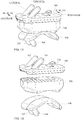
- an embodiment of the invention comprises an assembly that comprises a tibial implant 100, a talar implant 300, and an intermediate implant 200 that can fit between the tibial implant 100 and the talar implant 300.
- the tibial implant 100 may be suitable for implantation into or onto a prepared end of a tibia.
- the talar implant 300 may be suitable for implantation into or onto a prepared surface of a talus.
- the intermediate implant 200 may attach to tibial implant 100 and may articulate with respect to talar implant 300.
- Tibial implant 100 may comprise an anterior edge 101A and a posterior edge 101P, although it is understood that this nomenclature is only for sake of description.
- the tibial implant 100 may comprise a tibia-facing surface 102 and a lower surface 104 that is generally opposed to the tibia-facing surface 102.
- the tibia-facing surface 102 may comprise a portion that is generally flat.
- the lower surface 104 may comprise an outer surface 106, which may be flat, and an inner surface 108, which may be part of a cutout region and which may also may be flat.
- the cutout region defines a boundary with, as shown, first, second, and third internal boundary sides, 117, 119, and 121, respectively. It is not actually necessary that both the outer surface 106 and the inner surface 108 be flat, as other shapes are also possible in each case.
- the inner surface 108 of tibial implant 100 may have a centerline 109 generally along the anterior-posterior direction. Centerline 109 may be a line of symmetry of inner surface 108, which would be halfway between first boundary side 117 and second boundary side 119.
- the boundary between outer surface 106 and inner surface 108 may comprise first and second dovetails 122 and 124, which may be straight and parallel to each other. More generally, in that location there may be any geometry that allows a sliding capture of a complementary feature of intermediate implant 200.
- Connecting between first dovetail 122 and second dovetail 124 may be yet another segment of the boundary between outer surface 106 and inner surface 108. As illustrated, this segment may comprise a third dovetail 126, which may occupy at least a portion of a remainder of the cutout perimeter other than first dovetail 122 and second dovetail 124.
- Third dovetail 126 may be geometrically identical to first and second dovetails 122, 124, although it does not have to be.
- First dovetail 122 and second dovetail 124 may be generally straight and may be parallel to each other.
- Third dovetail 126 may also be straight and may be perpendicular to first dovetail 122 or second dovetail 124, although this is not essential. There may be a rounded corner between the first dovetail 122 and third dovetail 126, and similarly another rounded corner between second dovetail 124 and third dovetail 126. These rounded corners may comprise the same dovetail shape as on the first second and third dovetails 122, 124, 126.
- Third dovetail 126 may be complementary to a corresponding feature of intermediate implant 200.
- Entrance region 111 may be tapered or otherwise shaped so as to guide intermediate implant 200 into its desired position within side dovetails 122, 124.
- the projections may comprise a somewhat planar fin 130. It is possible that fin 130 may have one or more through-holes 132 therethrough. In cross-section taken perpendicular to its overall length direction, fin 130 may have two long sides 134, 136 and two short sides 138, 139. The two long sides 134, 136 may be part of flat surfaces that may be parallel or almost parallel to each other or may form a slight taper. Fin 130 may be sharp or wedge-shaped at its end away from tibia-facing surface 102 of tibial implant 100.
- the projections may also comprise one or more (two shown) tibial pegs 142, 144 that may be at least somewhat cylindrical.
- the joints where pegs 142, 144 join tibia-facing surface 102 may be located both on a common line that is perpendicular to a direction of the dovetails 122, 124.
- Tibial pegs 142, 144 preferably may be longer than fin 130.
- Tibial pegs 142, 144 preferably are located at a distance away from the centerline 109, and as such are inserted into the cancellous bone in the epiphysis. It is believed, although it is not wished to be limited to this explanation, that the use of a fin 130 may be helpful (compared to a peg, for example) in securing anchorage of tibial implant 100 into the bone of the distal portion of the tibia.
- the distal portion of the tibia is a region where the bone can be relatively soft, and the fin 130 has greater surface area than a peg would have, thereby securing its position more effectively.
- the fin 130 may be self-cutting into the bone, without requiring preparation such as the pre-drilling of a hole. All of this may allow placement of fin 130 in a position fairly far distal in the tibia, which may be helpful in anchoring to the tibia particularly in preventing the tibial implant 100 from separating from the tibia during various possible scenarios of motion by the patient. Additionally, the absence of need for hole preparation in the less-accessible distal region of the tibia would be a convenience for the surgeon.
- the projections may have a respective defined lengthwise direction.
- the lengthwise direction may be the axis of the cylinder or the axis of axisymmetry of the tibial peg 142, 144.
- Tibial pegs 142, 144 may have a portion of a sphere 148A at the tip of the peg, which may be followed by a portion of a cone 148B, which may be followed by surface 148C formed by a circular arc in revolution around the longitudinal axis of the tibial peg, which may be followed by a cylindrical surface 148D, It is believed, although it is not wished to be limited to this explanation, that such a shape of the tip of the tibial peg 142, 144 may be helpful in guiding the pegs 142, 144 into the corresponding hole prepared in the bone, which may involve a close fit between the peg 142, 144 and the prepared bone.
- the lengthwise direction may be an axis that is midway between respective opposed parallel exterior surfaces of the fin.
- the tibial implant 1 00 may have a midpoint that is halfway between the anterior-most extent of the tibial implant 100 and the posterior-most extent of tibial implant 100, and fin 130 may be entirely located posteriorly of the midpoint.
- the defined lengthwise direction of any of the projections may be inclined at an angle gamma with respect to the generally flat portion of tibia-facing surface 102 of tibial implant 100.
- the angle may be such that the angle gamma faces toward the posterior of tibial implant 100 and has an angular measure of between 0 and 90 degrees, more particularly between 20 and 70 degrees. As illustrated, the angle gamma is 45 degrees.
- Gamma is illustrated in Figure 2B as being identical for tibial pegs 142, 144 and for fin 130, but it is possible that the angle designated as gamma for tibial pegs 142, 144 could have a different value from the angle designated as gamma for fin 130.
- the inequality of angle could be in either direction, in terms of which angle is greater than which other angle.
- the respective lengthwise directions of at least some of the projections may be parallel to each other.
- the directional axis of fin 130 may be parallel to the respective axis of one or more tibial pegs 142, 144.
- the axis of a tibial peg 142, 144 may be parallel to a straight-line segment of a surface of the fin 130.
- Pegs 142, 144 and fin 130 may be spaced so as to occupy more than one position along the anterior-posterior direction of the tibial implant 100, i.e.
- pegs 142, 144 and fin 130 can be positioned so as to not all lie in a line running medial-lateral (not all in the same coronal plane). It is possible that pegs 142, 144 may occupy the same position as each other along the anterior-posterior direction of tibial implant 100, and fin 130 may occupy a different position (i.e. they can lie in the same coronal plane). Fin 130 may be more posterior than pegs 142, 144.
- Tibial implant 100 may further comprise a pocket 160, which may be recessed with respect to inner surface 108, As described elsewhere herein, pocket 160 may be dimensioned so as to cooperate with a feature of intermediate implant 200 to latch intermediate implant 200 to tibial implant 100.
- the pocket 160 of tibial implant 100 may have side edges that are parallel or at least approximately parallel to the first and second dovetails 122, 124 of tibial implant 100, or may have any other suitable geometry. Pocket 160 may be located either approximately or exactly midway between the first and second dovetails 122, 124 of tibial implant 100.
- tibial implant 100 may comprise a tibial implant recess 170, which may be located at the anterior edge 101A of tibial implant 100.
- Tibial implant recess 170 may have a lateral dimension that is substantially the same as the lateral dimension of pocket 160 or of latch 260 (described hereinafter) of intermediate implant 200.
- Tibial implant recess 170 may substantially align with pocket 160 along the direction of side dovetails 122, 124.
- Tibial implant recess 170 may be located either approximately or exactly midway between the side dovetails 122, 124 of tibial implant 100.
- FIG. 2F there is shown a top view of tibial implant 100 with the tibial implant 100 being a transparent wireframe so that features on the underside of tibial implant 100, such as dovetails 122, 124 and 126 and pocket 160 can be seen in relation to features on the upper side of tibial implant 100 such as pegs 142, 144 and fin 130.
- Figure 2G which is a three-dimensional perspective view, shows tibial implant 100 as a transparent wireframe so as to show the relative placement of certain features on the upper side and the underside. There may be certain relations between the placement of features on the upper side and the placement of features on the underside of tibial implant 100.
- Such relative placement can serve to connect protruding load-bearing features such as pegs 142, 144 and fin 130 to portions of tibial implant 100 that are structurally thick and strong. In other instances, such placement may overlap thicker stronger portions of tibial implant 100 with regions that are thinner and structurally weaker, and may thereby help to reinforce regions that are thinner and structurally weaker. As illustrated, the connection of fin 130 to tibial implant 100 is entirely within the region of dovetails 122, 124 and 126, i.e., the connection of fin 130 to tibial implant 100 is opposite the inner surface 108.
- connection of fin 130 could partially overlie the inner surface 108 within dovetails 122, 124 and 126 and could partly overlie the thicker portion of tibial implant 100, outer surface 106, that does not have dovetails 122, 124 and 126 cut out of it.
- Tibial pegs 142, 144 may, as illustrated, partially overlie the inner surface 108 within dovetails 122, 124 and 126 and partially overlie the thicker portion of tibial implant 100, outer surface 106, that does not have dovetails 122, 124 and 126 cut out of it. This could structurally reinforce the thinner portion (inner surface 108) of tibial implant 100.
- FIG. 2H and 2I there is shown a three-dimensional view of the tibial implant 100. upside-down compared to its orientation in Figure 2A . It can be seen that pocket 160 is recessed from inner surface 108. Entrance region 111 also is visible, as is tibial implant recess 170. Figure 2J shows the edges of first and second dovetails 122, 124 visible in this anterior view.
- the tibia-facing surface 102 may have an external shape that is chosen so as to match closely with the external shape of the prepared lower end of the tibia, when the tibia end is prepared as described elsewhere herein.
- the tibia as with bones generally, comprises an outer region of cortical bone that is relatively strong, and an inner region of cancellous bone that is more porous and less strong.
- the close matching of the external shape of the tibial implant to the outside perimeter shape of the prepared end of the lower tibia is believed to give good mechanical contact and load transfer between the tibial implant and the cortical region of the bone of the tibia. It is believed, although it is not wished to be limited to this explanation, that this close matching of shapes may decrease the likelihood of problems with subsidence of the tibial implant into the tibia.
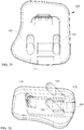
- the tibial implant 100 may, first of all, have a perimeter that has a certain external perimeter shape, as is best illustrated in Figures 2D and 2K.
- Figure 2K is a top view of the outside perimeter of tibial implant 100.
- the perimeter may, first of all have a first straight edge 190.
- the side dovetails 122, 124 of tibial implant 100 may be close to being parallel to straight external edge 190 of tibial implant 100, although as illustrated they are not exactly parallel.
- the tibial implant 100 may have an outer perimeter that can be described as follows, while commencing at a location on the lateral edge of the implant 100 at a posterior location and proceeding counterclockwise as viewed from above. From this vantage point, the perimeter may comprise: a first straight edge 190, which may be considered a vertical reference for purpose of illustration; followed by a first convex corner 191 that meets and is tangent to the first straight edge 190; followed by a second straight edge or shallow arc 192 that meets and is tangent to the first convex corner 191, wherein an angle alpha of the first convex corner 191 is greater than 90 degrees but less than 180 degrees; followed by a second convex corner 193 that meets and is tangent to the second straight edge or shallow arc 192; followed by a first concave curve 194, wherein the second convex corner 193 transitions to the first concave curve 194 at a first inflection point 1934.
- tangent line 195 that is parallel to first straight edge 190 and is tangent to second convex corner 193 at a tangency point 1953, wherein the tangency point 1953 is farther from first straight edge 190 than is first inflection point 1934.
- the second convex corner 193 and the first concave curve 194 have a common tangent line at the first inflection point 1934, wherein the tangent line to the curve at the inflection point 1934 forms an angle beta with respect to tangent line 195, with beta being greater than zero so that the perimeter shape is re-entrant with respect to the first straight edge 190.
- First concave curve 194 may then continue until it again crosses tangent line 195 so that the perimeter crosses tangent line 195 to become farther from first straight edge 190 than is tangent line 195.
- first concave curve 194 may be an arbitrary convex curve that returns to first straight edge 190 to form a complete perimeter of tibial plate 100.
- features such as first concave curve 194 may be located on the lateral side of the tibial implant 100, as distinguished from the medial side of the tibial implant 100.
- first straight edge 190 may be located on the medial side of tibial implant 100.
- first concave curve 194 may be followed by a third convex corner 196, wherein the first concave curve 194 transitions to the third convex corner 196 at a second inflection point 1946; third convex corner 196 may be followed by a first convex curve 197, wherein the third convex corner 196 transitions to the first convex curve 197 at a common tangency point; followed by a fourth convex corner 199, wherein the first convex curve 197 transitions to the fourth convex corner 199 at a common tangency point 198; wherein the fourth convex corner 199 continues on and meets and is tangent to the first straight edge 190.
- Intermediate implant 200 may comprise a top surface 202 that faces tibial implant 100.
- the intermediate implant 200 may have an external perimeter, when viewed from above, that is similar to the corresponding perimeter of tibial implant 100 which it touches, Intermediate implant 200 may have a top surface 202, which may be flat.
- Projection 204 may have projection surface 206, which may be flat and may be parallel to top surface 202.
- intermediate implant 200 may have external dovetails suitable to engage corresponding dovetails 122, 124, 126 of tibial implant 100.
- side dovetails 222 and 224 which may be parallel to each other.
- End dovetail 226 may be continuous with side dovetails 222, 224 through rounded corners. The rounded corners may also have dovetails, which may have the same cross-sectional shape as dovetails 222, 224, 226.
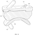
- the intermediate implant 200 may have a latch 260, which may project beyond the surface 202 of intermediate implant 200.
- Latch 260 may serve to lock intermediate implant 200 relative to tibial implant 100.
- the latch 260 may be shaped generally complementary to the pocket 160 in the tibial implant 100.
- the intermediate implant 200 may be capable of deforming or flexing slightly during insertion of the intermediate implant 200 into the tibial implant 100, to allow the latch 260 to attain its final position.
- the latch 260 itself may be capable of deforming or flexing slightly during insertion towards accomplishing a similar purpose.
- latch 260 could comprise a living hinge.
- intermediate implant 200 may comprise an intermediate implant recess 270, which may be located on the anterior edge of intermediate implant 200.
- Intermediate implant recess 270 may be located in a location similar to the location of recess 170 of tibial implant 100.
- Intermediate implant recess 270 may have a lateral dimension that is substantially the same as the lateral dimension of latch 260 of intermediate implant 200.
- Intermediate implant recess 270 may substantially align with latch 260 along the direction of side dovetails 122, 124.
- Tibial implant recess 170 may have an internal slope and latch 260 may have an external slope, and the tibial implant recess internal slope and the latch external slope may be equal to each other.
- intermediate implant 200 may have an opposed surface that is an articulating surface ( Figure 3E ).
- the articulating surface may comprise, as illustrated, two condyles, although other shapes are also possible.
- the first condylar articulating surface 272 and the second condylar articulating surface 274, as illustrated, may both be concave.
- first condylar surface 272, second condylar surface 274 and transition surface 276 may all be formed by respective circular arcs being revolved around an axis of revolution 399.
- the circular arc for first condylar surface 272 and the circular arc for second condylar surface 274 may have identical radii of curvature, although this is not essential.
- the circular arc for first condylar surface 272 and the circular arc for second condylar surface 274 both have a radius of curvature of 0.820 inch.
- transition surface 276 has a radius of curvature of 0.100 inch in the opposite sense from surfaces 272, 274. Variations from all of these dimensions would be possible.
- the respective sides of external dovetail 222, 224, 226 of intermediate implant 200 may have dimensions and shape that are complementary to those of the respective sides of internal dovetail 122, 124, 126. The relationship may be such as to allow the intermediate implant 200 to be slid into the tibial implant 100 and to be retained therein.
- the distance between the planes of outer surface 106 and inner surface 108 of tibial implant 100 may approximately equal or be slightly greater than the distance between the planes of top surface 202 and projection surface 206.
- the end external dovetail 226 of intermediate implant 200 may be complementary to the end internal dovetail 126 of tibial implant 100. The relationship may be such as to further help retain intermediate implant 200 to tibial implant 100.
- latch 260 of intermediate implant 200 may be complementary to pocket 160 in tibial implant 100 so as to allow latch 260 to reside within pocket 160 when intermediate implant 200 is assembled to tibial implant 100. Furthermore, the locations of latch 260 and pocket 160 may be such that this residing occurs when the side dovetails 222, 224 of intermediate implant 200 are engaged with the side dovetails 122, 124 of tibial implant 100, and when end dovetail 226 of intermediate implant 200 is engaged with the end dovetail 126 of tibial implant 100. The engagement of latch 260 with pocket 160 may coincide with engagement of end dovetail 226 with end dovetail 126.
- the distance between latch 260 and end dovetail 226 of intermediate implant 200 may be approximately equal to the distance between pocket 160 and end dovetail 126 of tibial implant 100. It can be noted that, in general, either one of the tibial implant 100 and the intermediate implant 200 may comprise a pocket and the other of the tibial implant 100 and the intermediate implant 200 may comprise a latch.
- tibial implant recess 170 may have a lateral dimension that is substantially the same as the lateral dimension of pocket 160 or of latch 260 of intermediate implant 200.
- Intermediate implant recess 270 may have a lateral dimension that is substantially the same as the lateral dimension of pocket 160 or of latch 260 of intermediate implant 200.
- Tibial implant recess 170 may substantially align with pocket 160 along the direction of side dovetails 122, 124.
- Intermediate implant recess 270 may substantially align with pocket 160 along the direction of side dovetails 122, 124.
- Intermediate implant recess 270 and tibial implant recess 170 may at least approximately align with each other to create a combined recess that may be suitable to receive and direct a surgical blade in the event that it is necessary to insert a surgical blade to cut off latch 260 for removal of intermediate implant 200 from tibial implant 100. It is possible that intermediate implant recess 270 alone could receive and direct a surgical blade in the event that it is necessary to insert a surgical blade to cut off latch 260, or tibial implant recess 170 alone could receive and direct a surgical blade in the event that it is necessary to insert a surgical blade to cut off latch 260.
- Intermediate implant 200 may have an outer perimeter, at or near the end that faces tibial implant 100, that is generally similar in shape and dimension to the outer the outer perimeter of tibial implant 100 at or near the end of tibial implant 100 that faces intermediate implant 200.
- pocket 160 of tibial implant 100 could instead be a protrusion and latch 260 of intermediate implant 200 could instead be a complementary void, or still other designs of latching or engaging features could be used.
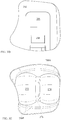
- Talar implant 300 may comprise a talar-facing surface 302 and an articulating surface that may be generally opposed to the talar-facing surface 302.
- Talar-facing surface may comprise three generally planar surfaces.
- the three planar surfaces may be anterior talar planar surface 306, central talar planar surface 307 and posterior talar planar surface 308. (It is not essential that any of these talar planar surfaces be planar.)
- the three generally planar surfaces 306, 307, 308 may appear, in cross-section when viewed from a lateral direction, as straight-line segments. Between adjacent planar surfaces 306, 307, 308 may be machining recesses or fillets 309A, 309B.
- the anterior talar-facing surface 306 may comprise one or more talar pegs. As illustrated, two talar pegs 342, 344 are provided. Talar pegs may be generally cylindrical with a rounded end. The shape of talar peg 342, 344 may be similar to the shape described for tibial pegs 142, 144. Each talar peg 342, 344 may comprise a piece of a sphere at the tip of the peg, followed by (tangent to) a cone, followed by a circular arc in revolution, followed by a cylinder.
- Talar pegs 342, 344 may each have a respective talar peg axis.
- the talar peg axis may have an angle delta, with respect to posterior talar planar surface 308, which is greater than zero as illustrated in Figure 4E .
- talar pegs 342, 344 could be parallel to posterior talar planar surface 308.
- talar peg 342 is completely within the lateral range of condylar articulating surface 372 of talar implant 300, and talar peg 344 is completely within the lateral range of condylar articulating surface 374.
- the articulating surface may comprise, as illustrated, two condyles, although other shapes are also possible.
- the first condylar articulating surface 372 and the second condylar articulating surface 374, as illustrated, may both be convex. However, in the region where the two condylar articulating surfaces approach each other, there may be a transition surface 376, which may be concave. As illustrated here and elsewhere herein, first condylar surface 372, second condylar surface 374 and transition surface 376 may all be formed by respective circular arcs being revolved around a common axis of revolution 399.
- the circular arc for first condylar surface 372 and the circular arc for second condylar surface 374 may have identical radii of curvature, although this is not essential.
- the circular arc for first condylar surface 372 and the circular arc for second condylar surface 374 both have a radius of curvature of 0.600 inch.
- transition surface 376 has a radius of curvature of 0.125 inch in the opposite sense from surfaces 372, 374. Variations from all of these dimensions would be possible.
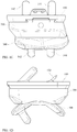
- Figure 4F illustrates the assembled total ankle replacement prosthesis with respect to nearby anatomy of a patient's body.
- axis of revolution 399 for forming condylar surfaces 272, 274 and transition surface 276, and for forming condylar surfaces 372, 374 and transition surface 376.
- the orientation of axis of revolution 399 relative to the anatomy is also illustrated.
- intermediate implant 200 may have a tibial-implant-facing surface 102 and an opposed surface that is an articulating surface.
- the articulating surface may, as illustrated, be bicondylar, although other shapes are also possible.
- Condylar surface 272 of intermediate implant 200 may be generally concave and condylar surface 274 of intermediate implant 200 may be generally concave, and between them may be transition region 276, which may be convex.
- first condylar surface 272 may be a surface formed by a first circular arc 272A whose center 272C is indicated with a cross.
- second condylar surface 274 may be a surface formed by a second circular arc 274A whose center 274C is similarly indicated.
- surface 276 may be formed by another arc 276A whose center 276C is indicated.
- the axis of revolution may be the same for all of circular arcs 272A, 274A, and 276A.
- circular arcs 272A, 274A may have identical radii of curvature with each other, although this is not essential.
- the orientation of the axis of rotation may be non-horizontal, such as angled 8 degrees with respect to horizontal, as illustrated in Figures. 4F and 5A .
- talar implant 300 may have a talus-facing surface 302 and an opposed surface that is an articulating surface.
- the articulating surface may, as illustrated, be bicondylar, although other shapes are also possible.
- Condylar surface 372 of talar implant 300 may be generally convex and condylar surface 374 of talar implant 300 may be generally convex, and between them may be transition region 376, which may be concave.
- first condylar surface 372 may be a surface formed by a first circular arc 372A whose center 372C is indicated with a cross.
- second condylar surface 374 may be a surface formed by another arc 372A whose center 374C is indicated.
- surface 376 may be formed by another arc 376A whose center 376C is indicated.
- the axis of revolution may be the same for all of circular arcs 372A, 374A, and 376A.
- circular arcs 372A, 374A may have identical radii of curvature with each other, although this is not essential.
- the orientation of the axis of rotation may be non-horizontal, such as for example it may be angled 8 degrees with respect to horizontal as illustrated in Figures 4F and 5B .
- the condylar surfaces of talar implant 300 and the condylar surfaces of intermediate implant 200 may exist certain geometric relationships between the condylar surfaces of talar implant 300 and the condylar surfaces of intermediate implant 200.
- the radii of curvature (illustrated as 0.820 inch) of the defining circular arcs 272A, 274A defining the concave condylar surfaces 272, 274 of the intermediate implant 200 may be larger than the corresponding radii of curvature (illustrated as 0.600 inch) of the defining circular arcs 372A, 374A defining the convex condylar surfaces 372, 374 of the talar implant 300.
- the arc of the condylar surfaces 272, 274 in the intermediate in-iplant 200 may extend over a larger distance or angular dimension than does the arc of the condylar surfaces 372, 374 in the talar implant 300, as can be seen by comparing Figures 5A and 5B .
- talar-facing surface 272, 274, 276 of intermediate implant 200 and for the intermediate-implant-facing surface 372, 374, 376 of talar implant 300 could be bicondylar.
- Such surfaces could be unicondylar or even spherical, or other shape as appropriate.
- the respective shapes may be generally complementary to each other.
- the articulating surface of the intermediate implant 200 is mostly concave (272, 274) and the articulating surface of the talar implant 300 is mostly convex (372, 374).
- the tibial implant 100 may be or may comprise a biocompatible metal.
- An example is titanium or a titanium alloy such as Ti - 6 Al - 4 V.
- Other biocompatible materials are also possible.
- the tibia-facing surface 102 of the tibial implant 100, and also fin 130 and pegs 142, 144 may comprise a material that is conducive to bone ingrowth or ongrowth, such as titanium or a titanium alloy. Such surface may be porous as desired to help promote bone ingrowth or ongrowth.
- some or all of the tibia-facing surface of the tibial implant 100 may be coated with a coating suitable to promote bone ingrowth or ongrowth. It is possible to use different materials in different places of any of these implants.
- the talar implant 300 may have any or all of the material characteristics just described for the tibial implant 100. If desired, some or all of the talus-facing surface of the talar implant 300, as well as talar pegs 342, 344, may be porous or may be coated with a coating suitable to promote bone ingrowth or ongrowth. It is possible to use different materials in different places of any of these implants.
- the intermediate implant 200 may comprise a biocompatible polymer.
- a biocompatible polymer For example, ultra high molecular weight polyethylene may be used.
- the material may be chosen to have good wear characteristics against the corresponding material of talar implant 300.
- Other materials such as ceramic are also possible.
- a ceramic material could be used for any of the components 100, 200, 300.
- FIG. 6A there is illustrated an intermediate implant 200N as was previously illustrated in Figure 3C .
- This intermediate implant 200N illustrated in Figure 6A is referred to as a neutral implant, as discussed here and elsewhere herein.
- the articulating talar condylar surfaces 272, 274 have an anterior edge 288A and a posterior edge 288P.
- the talar-facing surface may end at or may blend into an anterior planar surface.
- the posterior edge 288P the talar-facing surface may end at or may blend into a posterior planar surface.
- the anterior planar surface is coplanar with the posterior planar surface.
- intermediate implant 200 there may be defined a midplane of the intermediate implant that is a vertical plane of symmetry midway between the dovetails 222, 224 is generally parallel to a sagittal plane in the anatomical sense, and in that midplane there may be defined a contact line 292 that touches but does not intersect the anterior portion of the lower surface of intermediate implant 200, and also touches but does not intersect the posterior portion of the lower surface of intermediate implant 200.
- either or both of those contact points could be in the form of the contact line being tangent to a curve, or could be the line overlapping with a planar surface, or could be the line touching a corner point.
- the contact line 292 may be generally horizontal or parallel with the top surface 202 of intermediate implant 200.
- anterior edge 288A of the curved articulating surface of the intermediate implant 200 and a posterior edge 288P of the curved articulating surface of the intermediate implant 200 it is possible that the anterior edge 288A and the posterior edge 288P might not be at the same elevation, with elevation measured from a reference plane, such as a top surface 202 of the intermediate implant 200.
- offset "h" shows a distance from contact line 292, which is conversely able to be measured from the top surface 202.
- the articulating curved surface of the intermediate implant 200 can extend farther ( Figure 6B ) anter iorly than it does posteriorly, or, alternatively, the articulating curved surface of the intermediate implant 200 can extend farther posteriorly ( Figure 6C ) than it does anteriorly. It is possible that the use of unequal anterior and posterior angular extents of the articulating surfaces, or the unequal elevational positions of the corresponding endpoints of the articulating surfaces, could decrease the likelihood of subluxation in particular directions, as discussed elsewhere herein. This is illustrated in Figure 6B for an anterior-biased intermediate implant 200A, and in Figure 6C for a posterior-biased intermediate implant 200P.
- anterior edge 288A extends farther than the posterior edge 288P as in Figure 6B , this may reduce the likelihood of subluxation of the talus in the anterior direction relative to the tibia. If the posterior edge 288P extends further than the anterior edge 288A as in Figure 6C , this may reduce the likelihood of subluxation of the talus in the posterior direction relative to the tibia.
- intermediate implant 200A In particular, if the arc length of the articulating surface of intermediate implant 200A is extended in the anterior direction but not the posterior, and if this intermediate implant 200A is inserted surgically from the anterior-to-posterior direction after the tibial implant 100 and the talar implant 300 have already been implanted, this would not increase the difficulty of inserting the intermediate implant 200A, but it would provide greater protection against subluxation in the form of the foot or the talus subluxing or moving in an anterior direction with respect to the tibia.
- the anterior bias intermediate implant 200A may make it especially unlikely or difficult for subluxation to occur in the sense of the foot and talus subluxing in an anterior direction relative to the tibia.
- the posterior bias intermediate implant 200P may make it especially unlikely or difficult for subluxation to occur in the sense of the foot and talus subluxing in a posterior direction relative to the tibia.
- a kit may be provided that includes more than one type of implant, such as a neutral implant 200N, an anterior bias intermediate implant 200A and a posterior bias intermediate implant 200P.
- Each of those intermediate implants 200N, 200A, 200P may fit or be attachable to the same tibial implant 100.
- a surgeon can choose to use any of the various intermediate implants 200N, 200A, 200P as appropriate, while the tibial implant 100 and the talar implant 300 are unaffected by the choice of intermediate implant 200.
- the choice may be made based at least in part on the anatomy of the patient and the likelihood of any factors that might contribute to occurrence of subluxation.
- a kit contain more than one neutral intermediate implant 200N, with varying extents of arc.
- a neutral intermediate implant having a larger extent of arc in both front and rear directions would provide more protection against subluxation in both directions, although it could be more difficult to insert, in the sense of requiring greater stretching of surrounding tissues.
- any or all of the described components may be provided in mirror image versions corresponding to the left and right sides of a patient's body. Also, any or all components may be provided in multiple sizes.
- access to the ankle may be performed from the anterior of the ankle.
- a fixture may be anchored to the patient's leg externally to aid in determination of position of cuts.
- a cutting guide may be used to direct an oscillatory saw to remove the distal portion of the tibia.
- Working at an angle, possibly with a right-angle drill, drilling or other bone removal may be performed to the cut surface of the tibia such as to prepare for the pegs and the fin.
- the tibial implant 100 may be put into the surgical site, and may be hammered or urged in a posterior direction into its final position. So, the sharp end of the fin 130 may be advantageous in that the sharp end can force its own way into the tibial bone to some extent, as may be needed, upon application of force to the anterior end of the tibial implant 100 in a posterior direction.
- the fin 130 may help to prevent the posterior portion of tibial implant 100 from separating from the tibia upon certain motions by the patient.
- the talus can be prepared by cutting a series of flats into its surface, corresponding to the underside surface of talar implant 300. Holes can be drilled corresponding to talar pegs 342, 344. The talar implant 300 can be urged into place.
- the intermediate implant 200 may be slid into place. Intermediate implant 200 may be tapped or urged in a posterior direction until it engages with tibial implant 100.
- top should be understood as referring to an arbitrary frame of reference, rather than to the ordinary gravitational frame of reference.
- a top surface, a bottom surface, a front surface, and a rear surface may extend upwardly, downwardly, diagonally, or horizontally in a gravitational frame of reference.
- a phrase such as an "aspect” does not imply that such aspect is essential to the subject technology or that such aspect applies to all configurations of the subject technology.
- a disclosure relating to an aspect may apply to all configurations, or one or more configurations.
- a phrase such as an aspect may refer to one or more aspects and vice versa.
- a phrase such as an "embodiment” does not imply that such embodiment is essential to the subject technology or that such embodiment applies to all configurations of the subject technology.
- a disclosure relating to an embodiment may apply to all embodiments, or one or more embodiments.
- a phrase such an embodiment may refer to one or more embodiments and vice versa.
Description
- The present disclosure generally relates to systems and methods for replacement of an ankle by a prosthesis.
- Patients with certain types of ankle problems may require a total ankle replacement prosthesis. Although such devices have been used for some time, improvements are still needed in various respects, including but not limited to features that contribute to ease of implantation by a surgeon, resistance to posterior separation post-operatively, and resistance to component subsidence.
-
US 2005/143831 discloses a method for mounting a tibial condylar implant that includes forming a tunnel having a proximal end on a lateral, medial, or anterior side of a proximal end of the tibia and a distal end on an at least partially resected lateral or medial facet at the proximal end of the tibia. A condylar implant is positioned over the distal end of the tunnel, A fastener is advanced into the tunnel from the proximal end of the tunnel. The fastener which is at least partially disposed within the tunnel is secured to the condylar implant. -
WO 03/079938 -
GB 2018847 -
US 2011/295380 discloses a semi-constrained ankle prosthesis that includes a tibial component configured to be coupled to a surgically-prepared surface of the distal end of a tibia, and a bearing insert locked to the tibial component. The bearing insert is rotative relative to the tibial component and has an articular surface formed in an inferior surface thereof. - The invention is defined in the appended claims.
- The present disclosure addresses many of the problems encountered with prostheses for various anatomical joints, including but not limited to, total ankle replacement prostheses. Many of the features are particularly helpful when employed using an anterior approach, as opposed to a medial-lateral approach. Posterior separation resistance is aided with the use of a wedge entirely or partially on the posterior side of the tibial component. One or more pegs can be used to provide guidance for the wedge. Preferably the surgical technique involves no bone preparation beyond initial saw cutting, although preparation for the wedge or the pegs, or both, are possible. Component subsidence resistance is aided by minimizing bone resection and by maximizing the extent that the components rest on cortical bone rim. A lateral flare is utilized to cover the anterior cortical rim of the tibia, as opposed to traditional trapezoidal or oblong footprints found in many prior art designs. This lateral flare increases the contact area of the tibial tray with the cortical rim of the anterior tibia. The lateral flare follows the anatomic tibia shape in the transverse plane by wrapping around the anterior aspect of the fibula.
- The present disclosure provides a tibial implant, a talar implant and an intermediate implant, wherein the interi-Dediate implant fixedly attaches to the tibial implant and is capable of articulating with respect to the talar implant, wherein the intermediate implant has a first edge of the articulating surface and a second edge of the articulating surface, wherein the first edge is at a different elevation from the second edge, with elevation being defined with respect to a top surface of the intermediate implant.
- The present disclosure provides a kit comprising a tibial implant, a talar implant and a plurality of intermediate implants, wherein the intermediate implants attach to the tibial implant and have respective articulating surfaces that articulate with respect to the talar implant, wherein at least one of the intermediate implants has a different elevational dimension of the first end point from another of the intermediate implants or has a different elevational dimension of the second end point from another of the intermediate implants.
- The present disclosure provides a tibial implant, a talar implant and an intermediate implant, wherein the intermediate implant attaches to the tibial implant and is capable of articulating with respect to the talar implant, wherein one of the tibial implant and the intermediate implant comprises a pocket and the other of the tibial implant and the intermediate implant comprises a latch, the latch and the pocket engaging with each other upon assembly, wherein the intermediate implant comprises an intermediate implant recess on an anterior edge thereof, and wherein when viewed along an anterior-posterior direction, the intermediate implant recess at least partially aligns with the pocket and the latch.
- The present disclosure provides a tibial implant, a talar implant and an intermediate implant, wherein the intermediate implant attaches to the tibial implant and is capable of articulating with respect to the talar implant, wherein the tibial implant has a tibia-facing surface and a lower surface opposed to the tibia-facing surface, wherein the lower surface has a cutout region extending in from an exterior perimeter of the tibial implant, the cutout region defined by a cutout perimeter shape that demarcates the cutout region from a remainder of the lower surface of the tibial implant, wherein the cutout perimeter has a tibial dovetail configuration, wherein the tibial dovetail configuration extends along two sides and at least a portion of a remainder of the cutout perimeter, and wherein the intermediate implant comprises an intermediate implant dovetail having an intermediate implant dovetail configuration that is complementary to the tibial dovetail configuration.
- The present disclosure provides a tibial implant, a talar implant, and an intermediate implant fitting between the tibial implant and the talar implant, wherein the tibial implant has a tibia-facing surface and a lower surface opposed to the tibia-facing surface, wherein the lower surface has a cutout region defined by a perimeter shape demarcating the cutout region and a non-cutout region, the perimeter shape meeting an anterior edge of the tibial implant, wherein the tibia-facing surface has at least one tibial peg protruding therefrom and attached to the tibia-facing surface at an attachment region, wherein, as viewed along a direction perpendicular to the tibia-facing surface, the attachment region partially overlies the non-cutout region and partially overlies the cutout region.
- The present disclosure provides a tibial implant comprising a tibia-facing surface and an opposed surface, wherein the tibia-facing side comprises a flat surface; and two pegs protruding from the tibia-facing surface; and a fin protruding from the tibia-facing surface, wherein, in a cross-section taken perpendicular to its long direction, the fin has a wide direction and a narrow direction, the wide direction being longer than the narrow direction, and the wide direction being generally perpendicular to a direction of advancement of the tibial implant, wherein the fin has a wedge-shaped end away from the tibia-facing surface that is, wherein the pegs are at least partially axisymmetric having respective axes of symmetry, wherein an anterior edge of the tibial implant is an edge having a cutout therein and a posterior direction is a direction that is opposed to the anterior edge, and the fin is more posterior than the pegs, wherein the fin has a fin centerline and the pegs have respective peg axes of symmetry, and the peg axes of symmetry and the fin centerline are all substantially parallel to each other.
- The accompanying drawings, which are included to provide further understanding and are incorporated in and constitute a part of this specification, illustrate disclosed embodiments and together with the description serve to explain the principles of the disclosed embodiments. In the drawings:
-
Figure 1A shows a three-dimensional view of an embodiment of the invention, in its assembled configuration. -
Figure 1B shows the same three-dimensional view of an embodiment of the invention, in an exploded configuration, -
Figure 1C shows a front view of an embodiment of the invention. -
Figure 1D shows a side view of an embodiment of the invention, -
Figure 1E shows a three-dimensional view of a section of an embodiment of the invention, as defined inFigure 1A . -
Figure 2A shows a three-dimensional view of the tibial implant. -
Figure 2B is a side view of the tibial implant. -
Figure 2C is a front view of the tibial implant. -
Figure 2D is a top view of the tibial implant. -
Figure 2E is a bottom view of the tibial implant. -
Figure 2F is a top view of the tibial implant as if it were transparent. -
Figure 2G is a three-dimensional view of the tibial implant as if it were transparent. -
Figure 2H shows a three-dimensional view of the tibial implant, upside-down compared to its orientation inFigure 2A . -
Figure 2I is a three-dimensional view of a section of the tibial implant, as defined inFigure 2H . -
Figure 2J is a frontal view of the tibial implant similar toFigure 2C , but with sectioning removing the posterior portion of the tibial implant, so as to make the dovetail more visible. -
Figure 2K is a top view of the tibial implant similar toFigure 2D , but with specific reference to the external perimeter of the tibial implant. -
Figure 3A is a three-dimensional view of an intermediate implant. -
Figure 3B is a front view of the intermediate implant ofFigure 3A . -
Figure 3C a side view of the intermediate implant ofFigure 3A . -
Figure 3D is a top view of the intermediate implant ofFigure 3A . -
Figure 3E is a bottom view of the intermediate implant ofFigure 3A . -
Figure 3F is a three-dimensional sectional view of the tibial implant and the intermediate implant showing especially the recesses at the anterior of the tibial implant and the intermediate implant and the latch of the intermediate implant and the pocket of the tibial implant. -
Figure 3G is a three-dimensional sectional view of the tibial implant and the intermediate implant showing especially the latch of the intermediate implant and the cutout and the pocket of the tibial implant. -
Figure 4A is a three-dimensional view of a talar implant, somewhat from above. -
Figure 4B is a three-dimensional view of the talar implant ofFigure 4A , somewhat from below. -
Figure 4C is a top view of the talar implant ofFigure 4A . -
Figure 4D is a frontal view of the talar implant ofFigure 4A . -
Figure 4E is a side view of the talar implant ofFigure 4A . -
Figure 4F is a frontal view of an implanted prosthesis, with the intermediate implant shown transparent, with certain anatomical features of the ankle also shown schematically. -
Figure 5A is an illustration of the shape, in cross-section, of the bicondylar surface of the intermediate implant. -
Figure 5B is an illustration of the shape, in cross-section, of the bicondylar surface of the talar implant. -
Figure 6A is a side view of an intermediate implant similar to that ofFigure 3A , which may be referred to as a neutral intermediate implant. -
Figure 6B is a side view of an intermediate implant that may be referred to as an anterior-biased intermediate implant. -
Figure 6C is a side view of an intermediate implant that may be referred to as a posterior-biased intermediate implant. - The following description discloses embodiments of a total ankle replacement device.
- In the following detailed description, numerous specific details are set forth to provide a full understanding of the present disclosure. It will be apparent, however, to one ordinarily skilled in the art that embodiments of the present disclosure may be practiced without some of the specific details. In other instances, well-known structures and techniques have not been shown in detail so as not to obscure the disclosure.
- The method and system disclosed herein are presented in terms of a device for use in the ankle. It will be obvious to those of ordinary skill in the art that this same configuration and method can be utilized in a variety of applications that require a prosthesis that provides motion. Nothing in this disclosure should be interpreted, unless specifically stated as such, to limit the application of any method or system disclosed herein to the ankle.
- Referring now to
Figures 1A through 1E , an embodiment of the invention comprises an assembly that comprises atibial implant 100, atalar implant 300, and anintermediate implant 200 that can fit between thetibial implant 100 and thetalar implant 300. Thetibial implant 100 may be suitable for implantation into or onto a prepared end of a tibia. Thetalar implant 300 may be suitable for implantation into or onto a prepared surface of a talus. Theintermediate implant 200 may attach totibial implant 100 and may articulate with respect totalar implant 300. - Referring now to
Figures 2A through 2K , there is shown atibial implant 100.Tibial implant 100 may comprise ananterior edge 101A and aposterior edge 101P, although it is understood that this nomenclature is only for sake of description. Thetibial implant 100 may comprise a tibia-facingsurface 102 and alower surface 104 that is generally opposed to the tibia-facingsurface 102. The tibia-facingsurface 102 may comprise a portion that is generally flat. - The
lower surface 104 may comprise anouter surface 106, which may be flat, and aninner surface 108, which may be part of a cutout region and which may also may be flat. The cutout region defines a boundary with, as shown, first, second, and third internal boundary sides, 117, 119, and 121, respectively. It is not actually necessary that both theouter surface 106 and theinner surface 108 be flat, as other shapes are also possible in each case. Theinner surface 108 oftibial implant 100 may have acenterline 109 generally along the anterior-posterior direction.Centerline 109 may be a line of symmetry ofinner surface 108, which would be halfway betweenfirst boundary side 117 andsecond boundary side 119. - The boundary between
outer surface 106 andinner surface 108 may comprise first and second dovetails 122 and 124, which may be straight and parallel to each other. More generally, in that location there may be any geometry that allows a sliding capture of a complementary feature ofintermediate implant 200. Connecting betweenfirst dovetail 122 andsecond dovetail 124 may be yet another segment of the boundary betweenouter surface 106 andinner surface 108. As illustrated, this segment may comprise athird dovetail 126, which may occupy at least a portion of a remainder of the cutout perimeter other thanfirst dovetail 122 andsecond dovetail 124.Third dovetail 126 may be geometrically identical to first and second dovetails 122, 124, although it does not have to be.First dovetail 122 andsecond dovetail 124 may be generally straight and may be parallel to each other.Third dovetail 126 may also be straight and may be perpendicular tofirst dovetail 122 orsecond dovetail 124, although this is not essential. There may be a rounded corner between thefirst dovetail 122 andthird dovetail 126, and similarly another rounded corner betweensecond dovetail 124 andthird dovetail 126. These rounded corners may comprise the same dovetail shape as on the first second and third dovetails 122, 124, 126.Third dovetail 126 may be complementary to a corresponding feature ofintermediate implant 200. At theanterior edge 101A oftibial implant 100, there may be provided anentrance region 111 to dovetails 122, 124 such that theentrance region 111 is wider in the medial-lateral direction than the space between dovetails 122, 124.Entrance region 111 may be tapered or otherwise shaped so as to guideintermediate implant 200 into its desired position within side dovetails 122, 124. - Extending from the tibia-facing
surface 102 may be a plurality of projections. The projections may comprise a somewhatplanar fin 130. It is possible thatfin 130 may have one or more through-holes 132 therethrough. In cross-section taken perpendicular to its overall length direction,fin 130 may have twolong sides short sides long sides Fin 130 may be sharp or wedge-shaped at its end away from tibia-facingsurface 102 oftibial implant 100. The projections may also comprise one or more (two shown) tibial pegs 142, 144 that may be at least somewhat cylindrical. The joints wherepegs surface 102 may be located both on a common line that is perpendicular to a direction of the dovetails 122, 124. Tibial pegs 142, 144 preferably may be longer thanfin 130. Tibial pegs 142, 144 preferably are located at a distance away from thecenterline 109, and as such are inserted into the cancellous bone in the epiphysis. It is believed, although it is not wished to be limited to this explanation, that the use of afin 130 may be helpful (compared to a peg, for example) in securing anchorage oftibial implant 100 into the bone of the distal portion of the tibia. The distal portion of the tibia is a region where the bone can be relatively soft, and thefin 130 has greater surface area than a peg would have, thereby securing its position more effectively. Also, thefin 130 may be self-cutting into the bone, without requiring preparation such as the pre-drilling of a hole. All of this may allow placement offin 130 in a position fairly far distal in the tibia, which may be helpful in anchoring to the tibia particularly in preventing thetibial implant 100 from separating from the tibia during various possible scenarios of motion by the patient. Additionally, the absence of need for hole preparation in the less-accessible distal region of the tibia would be a convenience for the surgeon. - At least some of the projections may have a respective defined lengthwise direction. For a projection such as tibial pegs 142, 144 that is at least partly cylindrical or axisymmetric, the lengthwise direction may be the axis of the cylinder or the axis of axisymmetry of the
tibial peg sphere 148A at the tip of the peg, which may be followed by a portion of acone 148B, which may be followed bysurface 148C formed by a circular arc in revolution around the longitudinal axis of the tibial peg, which may be followed by acylindrical surface 148D, It is believed, although it is not wished to be limited to this explanation, that such a shape of the tip of thetibial peg pegs peg fin 130, the lengthwise direction may be an axis that is midway between respective opposed parallel exterior surfaces of the fin. As illustrated, thetibial implant 1 00 may have a midpoint that is halfway between the anterior-most extent of thetibial implant 100 and the posterior-most extent oftibial implant 100, andfin 130 may be entirely located posteriorly of the midpoint. - The defined lengthwise direction of any of the projections may be inclined at an angle gamma with respect to the generally flat portion of tibia-facing
surface 102 oftibial implant 100. The angle may be such that the angle gamma faces toward the posterior oftibial implant 100 and has an angular measure of between 0 and 90 degrees, more particularly between 20 and 70 degrees. As illustrated, the angle gamma is 45 degrees. Gamma is illustrated inFigure 2B as being identical fortibial pegs fin 130, but it is possible that the angle designated as gamma for tibial pegs 142, 144 could have a different value from the angle designated as gamma forfin 130. The inequality of angle could be in either direction, in terms of which angle is greater than which other angle. - The respective lengthwise directions of at least some of the projections (tibial pegs 142, 144 and fin 130) may be parallel to each other. The directional axis of
fin 130 may be parallel to the respective axis of one or more tibial pegs 142, 144. Alternatively, the axis of atibial peg fin 130.Pegs fin 130 may be spaced so as to occupy more than one position along the anterior-posterior direction of thetibial implant 100, i.e. pegs 142, 144 andfin 130 can be positioned so as to not all lie in a line running medial-lateral (not all in the same coronal plane). It is possible that pegs 142, 144 may occupy the same position as each other along the anterior-posterior direction oftibial implant 100, andfin 130 may occupy a different position (i.e. they can lie in the same coronal plane).Fin 130 may be more posterior thanpegs -
Tibial implant 100 may further comprise apocket 160, which may be recessed with respect toinner surface 108, As described elsewhere herein,pocket 160 may be dimensioned so as to cooperate with a feature ofintermediate implant 200 to latchintermediate implant 200 totibial implant 100. Thepocket 160 oftibial implant 100 may have side edges that are parallel or at least approximately parallel to the first and second dovetails 122, 124 oftibial implant 100, or may have any other suitable geometry.Pocket 160 may be located either approximately or exactly midway between the first and second dovetails 122, 124 oftibial implant 100. - It is further possible that
tibial implant 100 may comprise atibial implant recess 170, which may be located at theanterior edge 101A oftibial implant 100.Tibial implant recess 170 may have a lateral dimension that is substantially the same as the lateral dimension ofpocket 160 or of latch 260 (described hereinafter) ofintermediate implant 200.Tibial implant recess 170 may substantially align withpocket 160 along the direction of side dovetails 122, 124.Tibial implant recess 170 may be located either approximately or exactly midway between the side dovetails 122, 124 oftibial implant 100. - Referring now to
Figure 2F , there is shown a top view oftibial implant 100 with thetibial implant 100 being a transparent wireframe so that features on the underside oftibial implant 100, such as dovetails 122, 124 and 126 andpocket 160 can be seen in relation to features on the upper side oftibial implant 100 such aspegs fin 130. Similarly,Figure 2G , which is a three-dimensional perspective view, showstibial implant 100 as a transparent wireframe so as to show the relative placement of certain features on the upper side and the underside. There may be certain relations between the placement of features on the upper side and the placement of features on the underside oftibial implant 100. Such relative placement can serve to connect protruding load-bearing features such aspegs fin 130 to portions oftibial implant 100 that are structurally thick and strong. In other instances, such placement may overlap thicker stronger portions oftibial implant 100 with regions that are thinner and structurally weaker, and may thereby help to reinforce regions that are thinner and structurally weaker. As illustrated, the connection offin 130 totibial implant 100 is entirely within the region of dovetails 122, 124 and 126, i.e., the connection offin 130 totibial implant 100 is opposite theinner surface 108. However, it would also have been possible that the connection offin 130 could partially overlie theinner surface 108 within dovetails 122, 124 and 126 and could partly overlie the thicker portion oftibial implant 100,outer surface 106, that does not have dovetails 122, 124 and 126 cut out of it. Tibial pegs 142, 144 may, as illustrated, partially overlie theinner surface 108 within dovetails 122, 124 and 126 and partially overlie the thicker portion oftibial implant 100,outer surface 106, that does not have dovetails 122, 124 and 126 cut out of it. This could structurally reinforce the thinner portion (inner surface 108) oftibial implant 100. - Referring now to
Figures 2H and 2I , there is shown a three-dimensional view of thetibial implant 100. upside-down compared to its orientation inFigure 2A . It can be seen thatpocket 160 is recessed frominner surface 108.Entrance region 111 also is visible, as istibial implant recess 170.Figure 2J shows the edges of first and second dovetails 122, 124 visible in this anterior view. - Referring now to
Figure 2K , the tibia-facingsurface 102 may have an external shape that is chosen so as to match closely with the external shape of the prepared lower end of the tibia, when the tibia end is prepared as described elsewhere herein. The tibia, as with bones generally, comprises an outer region of cortical bone that is relatively strong, and an inner region of cancellous bone that is more porous and less strong. The close matching of the external shape of the tibial implant to the outside perimeter shape of the prepared end of the lower tibia is believed to give good mechanical contact and load transfer between the tibial implant and the cortical region of the bone of the tibia. It is believed, although it is not wished to be limited to this explanation, that this close matching of shapes may decrease the likelihood of problems with subsidence of the tibial implant into the tibia. - The
tibial implant 100 may, first of all, have a perimeter that has a certain external perimeter shape, as is best illustrated inFigures 2D and2K. Figure 2K is a top view of the outside perimeter oftibial implant 100. The perimeter may, first of all have a firststraight edge 190. The side dovetails 122, 124 oftibial implant 100 may be close to being parallel to straightexternal edge 190 oftibial implant 100, although as illustrated they are not exactly parallel. - The
tibial implant 100 may have an outer perimeter that can be described as follows, while commencing at a location on the lateral edge of theimplant 100 at a posterior location and proceeding counterclockwise as viewed from above. From this vantage point, the perimeter may comprise: a firststraight edge 190, which may be considered a vertical reference for purpose of illustration; followed by a first convex corner 191 that meets and is tangent to the firststraight edge 190; followed by a second straight edge orshallow arc 192 that meets and is tangent to the first convex corner 191, wherein an angle alpha of the first convex corner 191 is greater than 90 degrees but less than 180 degrees; followed by a secondconvex corner 193 that meets and is tangent to the second straight edge orshallow arc 192; followed by a firstconcave curve 194, wherein the secondconvex corner 193 transitions to the firstconcave curve 194 at afirst inflection point 1934. It may be considered that there is atangent line 195 that is parallel to firststraight edge 190 and is tangent to secondconvex corner 193 at atangency point 1953, wherein thetangency point 1953 is farther from firststraight edge 190 than isfirst inflection point 1934. The secondconvex corner 193 and the firstconcave curve 194 have a common tangent line at thefirst inflection point 1934, wherein the tangent line to the curve at theinflection point 1934 forms an angle beta with respect totangent line 195, with beta being greater than zero so that the perimeter shape is re-entrant with respect to the firststraight edge 190. Firstconcave curve 194 may then continue until it again crossestangent line 195 so that the perimeter crossestangent line 195 to become farther from firststraight edge 190 than istangent line 195. Continuing on from firstconcave curve 194 may be an arbitrary convex curve that returns to firststraight edge 190 to form a complete perimeter oftibial plate 100. In an anatomical sense, features such as firstconcave curve 194 may be located on the lateral side of thetibial implant 100, as distinguished from the medial side of thetibial implant 100. Correspondingly, firststraight edge 190 may be located on the medial side oftibial implant 100. - As illustrated, first
concave curve 194 may be followed by a thirdconvex corner 196, wherein the firstconcave curve 194 transitions to the thirdconvex corner 196 at asecond inflection point 1946; thirdconvex corner 196 may be followed by a firstconvex curve 197, wherein the thirdconvex corner 196 transitions to the firstconvex curve 197 at a common tangency point; followed by a fourthconvex corner 199, wherein the firstconvex curve 197 transitions to the fourthconvex corner 199 at acommon tangency point 198; wherein the fourthconvex corner 199 continues on and meets and is tangent to the firststraight edge 190. - Referring now to
Figures 3A-3E , there is shownintermediate implant 200.Intermediate implant 200 may comprise atop surface 202 that facestibial implant 100. First of all, theintermediate implant 200 may have an external perimeter, when viewed from above, that is similar to the corresponding perimeter oftibial implant 100 which it touches,Intermediate implant 200 may have atop surface 202, which may be flat. There may be aprojection 204 protruding fromtop surface 202.Projection 204 may haveprojection surface 206, which may be flat and may be parallel totop surface 202. Betweentop surface 202 andprojection surface 206,intermediate implant 200 may have external dovetails suitable to engage corresponding dovetails 122, 124, 126 oftibial implant 100. There may be side dovetails 222 and 224, which may be parallel to each other. There may further beend dovetail 226.End dovetail 226 may be continuous with side dovetails 222, 224 through rounded corners. The rounded corners may also have dovetails, which may have the same cross-sectional shape as dovetails 222, 224, 226. - The
intermediate implant 200 may have alatch 260, which may project beyond thesurface 202 ofintermediate implant 200.Latch 260 may serve to lockintermediate implant 200 relative totibial implant 100. Thelatch 260 may be shaped generally complementary to thepocket 160 in thetibial implant 100. Theintermediate implant 200 may be capable of deforming or flexing slightly during insertion of theintermediate implant 200 into thetibial implant 100, to allow thelatch 260 to attain its final position. Alternatively, or in addition, thelatch 260 itself may be capable of deforming or flexing slightly during insertion towards accomplishing a similar purpose. For example, latch 260 could comprise a living hinge. - It is further possible that
intermediate implant 200 may comprise anintermediate implant recess 270, which may be located on the anterior edge ofintermediate implant 200.Intermediate implant recess 270 may be located in a location similar to the location ofrecess 170 oftibial implant 100.Intermediate implant recess 270 may have a lateral dimension that is substantially the same as the lateral dimension oflatch 260 ofintermediate implant 200.Intermediate implant recess 270 may substantially align withlatch 260 along the direction of side dovetails 122, 124.Tibial implant recess 170 may have an internal slope and latch 260 may have an external slope, and the tibial implant recess internal slope and the latch external slope may be equal to each other. - Opposite to tibia-facing
top surface 202,intermediate implant 200 may have an opposed surface that is an articulating surface (Figure 3E ). The articulating surface may comprise, as illustrated, two condyles, although other shapes are also possible. The firstcondylar articulating surface 272 and the secondcondylar articulating surface 274, as illustrated, may both be concave. However, in the region where the two condylar articulating surfaces approach each other, there may be atransition surface 276, which may be convex. As illustrated here and elsewhere herein, firstcondylar surface 272, secondcondylar surface 274 andtransition surface 276 may all be formed by respective circular arcs being revolved around an axis ofrevolution 399. Furthermore, as illustrated inFigures 5A and 5B , the circular arc for firstcondylar surface 272 and the circular arc for secondcondylar surface 274 may have identical radii of curvature, although this is not essential. As illustrated, the circular arc for firstcondylar surface 272 and the circular arc for secondcondylar surface 274 both have a radius of curvature of 0.820 inch. As illustrated,transition surface 276 has a radius of curvature of 0.100 inch in the opposite sense fromsurfaces - Referring now to
Figures 3F-3G , there may exist certain geometric relationships that relate features oftibial implant 100 and features ofintermediate implant 200. In regard to dovetail features, the respective sides ofexternal dovetail intermediate implant 200 may have dimensions and shape that are complementary to those of the respective sides ofinternal dovetail intermediate implant 200 to be slid into thetibial implant 100 and to be retained therein. The distance between the planes ofouter surface 106 andinner surface 108 oftibial implant 100 may approximately equal or be slightly greater than the distance between the planes oftop surface 202 andprojection surface 206. Also, the endexternal dovetail 226 ofintermediate implant 200 may be complementary to the endinternal dovetail 126 oftibial implant 100. The relationship may be such as to further help retainintermediate implant 200 totibial implant 100. - In regard to latching features, latch 260 of
intermediate implant 200 may be complementary topocket 160 intibial implant 100 so as to allowlatch 260 to reside withinpocket 160 whenintermediate implant 200 is assembled totibial implant 100. Furthermore, the locations oflatch 260 andpocket 160 may be such that this residing occurs when the side dovetails 222, 224 ofintermediate implant 200 are engaged with the side dovetails 122, 124 oftibial implant 100, and when end dovetail 226 ofintermediate implant 200 is engaged with theend dovetail 126 oftibial implant 100. The engagement oflatch 260 withpocket 160 may coincide with engagement ofend dovetail 226 withend dovetail 126. The distance betweenlatch 260 and enddovetail 226 ofintermediate implant 200 may be approximately equal to the distance betweenpocket 160 and enddovetail 126 oftibial implant 100. It can be noted that, in general, either one of thetibial implant 100 and theintermediate implant 200 may comprise a pocket and the other of thetibial implant 100 and theintermediate implant 200 may comprise a latch. - In regard to recesses at the anterior edges of
tibial implant 100 andintermediate implant 200,tibial implant recess 170 may have a lateral dimension that is substantially the same as the lateral dimension ofpocket 160 or oflatch 260 ofintermediate implant 200.Intermediate implant recess 270 may have a lateral dimension that is substantially the same as the lateral dimension ofpocket 160 or oflatch 260 ofintermediate implant 200.Tibial implant recess 170 may substantially align withpocket 160 along the direction of side dovetails 122, 124.Intermediate implant recess 270 may substantially align withpocket 160 along the direction of side dovetails 122, 124.Intermediate implant recess 270 andtibial implant recess 170 may at least approximately align with each other to create a combined recess that may be suitable to receive and direct a surgical blade in the event that it is necessary to insert a surgical blade to cut offlatch 260 for removal ofintermediate implant 200 fromtibial implant 100. It is possible thatintermediate implant recess 270 alone could receive and direct a surgical blade in the event that it is necessary to insert a surgical blade to cut offlatch 260, ortibial implant recess 170 alone could receive and direct a surgical blade in the event that it is necessary to insert a surgical blade to cut offlatch 260. -
Intermediate implant 200 may have an outer perimeter, at or near the end that facestibial implant 100, that is generally similar in shape and dimension to the outer the outer perimeter oftibial implant 100 at or near the end oftibial implant 100 that facesintermediate implant 200. - Of course, it is also possible that
pocket 160 oftibial implant 100 could instead be a protrusion and latch 260 ofintermediate implant 200 could instead be a complementary void, or still other designs of latching or engaging features could be used. - Referring now to
Figures 4A-4E , there is illustrated atalar implant 300.Anterior edge 301A andposterior edge 301P are illustrated, although this is only for descriptive purposes.Talar implant 300 may comprise a talar-facingsurface 302 and an articulating surface that may be generally opposed to the talar-facingsurface 302. Talar-facing surface may comprise three generally planar surfaces. The three planar surfaces may be anterior talarplanar surface 306, central talarplanar surface 307 and posterior talarplanar surface 308. (It is not essential that any of these talar planar surfaces be planar.) The three generallyplanar surfaces planar surfaces fillets - The anterior talar-facing
surface 306 may comprise one or more talar pegs. As illustrated, two talar pegs 342, 344 are provided. Talar pegs may be generally cylindrical with a rounded end. The shape oftalar peg tibial pegs talar peg talar peg planar surface 308, which is greater than zero as illustrated inFigure 4E . Alternatively, talar pegs 342, 344 could be parallel to posterior talarplanar surface 308. As illustrated and as is particularly visible inFigure 4D , when viewed from the front (anterior), talar peg 342 is completely within the lateral range ofcondylar articulating surface 372 oftalar implant 300, and talar peg 344 is completely within the lateral range ofcondylar articulating surface 374. - The articulating surface may comprise, as illustrated, two condyles, although other shapes are also possible. The first
condylar articulating surface 372 and the secondcondylar articulating surface 374, as illustrated, may both be convex. However, in the region where the two condylar articulating surfaces approach each other, there may be atransition surface 376, which may be concave. As illustrated here and elsewhere herein, firstcondylar surface 372, secondcondylar surface 374 andtransition surface 376 may all be formed by respective circular arcs being revolved around a common axis ofrevolution 399. Furthermore, as illustrated, the circular arc for firstcondylar surface 372 and the circular arc for secondcondylar surface 374 may have identical radii of curvature, although this is not essential. As illustrated, the circular arc for firstcondylar surface 372 and the circular arc for secondcondylar surface 374 both have a radius of curvature of 0.600 inch. As illustrated,transition surface 376 has a radius of curvature of 0.125 inch in the opposite sense fromsurfaces -
Figure 4F illustrates the assembled total ankle replacement prosthesis with respect to nearby anatomy of a patient's body. In particular, there is illustrated axis ofrevolution 399 for formingcondylar surfaces transition surface 276, and for formingcondylar surfaces transition surface 376. The orientation of axis ofrevolution 399 relative to the anatomy is also illustrated. - Referring now to
Figure 5A ,intermediate implant 200 may have a tibial-implant-facingsurface 102 and an opposed surface that is an articulating surface. The articulating surface may, as illustrated, be bicondylar, although other shapes are also possible.Condylar surface 272 ofintermediate implant 200 may be generally concave andcondylar surface 274 ofintermediate implant 200 may be generally concave, and between them may betransition region 276, which may be convex. As illustrated, firstcondylar surface 272 may be a surface formed by a firstcircular arc 272A whosecenter 272C is indicated with a cross. Similarly, secondcondylar surface 274 may be a surface formed by a secondcircular arc 274A whosecenter 274C is similarly indicated. Similarly,surface 276 may be formed by anotherarc 276A whosecenter 276C is indicated. The axis of revolution may be the same for all ofcircular arcs circular arcs Figures. 4F and5A . - Referring now to
Figure 5B ,talar implant 300 may have a talus-facingsurface 302 and an opposed surface that is an articulating surface. The articulating surface may, as illustrated, be bicondylar, although other shapes are also possible.Condylar surface 372 oftalar implant 300 may be generally convex andcondylar surface 374 oftalar implant 300 may be generally convex, and between them may betransition region 376, which may be concave. As illustrated, firstcondylar surface 372 may be a surface formed by a firstcircular arc 372A whosecenter 372C is indicated with a cross. Similarly, secondcondylar surface 374 may be a surface formed by anotherarc 372A whosecenter 374C is indicated. Similarly,surface 376 may be formed by anotherarc 376A whosecenter 376C is indicated. The axis of revolution may be the same for all ofcircular arcs circular arcs Figures 4F and5B . - There may exist certain geometric relationships between the condylar surfaces of
talar implant 300 and the condylar surfaces ofintermediate implant 200. Specifically, the radii of curvature (illustrated as 0.820 inch) of the definingcircular arcs intermediate implant 200 may be larger than the corresponding radii of curvature (illustrated as 0.600 inch) of the definingcircular arcs talar implant 300. Also, the arc of thecondylar surfaces iplant 200 may extend over a larger distance or angular dimension than does the arc of thecondylar surfaces talar implant 300, as can be seen by comparingFigures 5A and 5B . - It can be noted that it is not necessary for the talar-facing
surface intermediate implant 200 and for the intermediate-implant-facingsurface talar implant 300 to be bicondylar. Such surfaces could be unicondylar or even spherical, or other shape as appropriate. The respective shapes may be generally complementary to each other. As has been illustrated, the articulating surface of theintermediate implant 200 is mostly concave (272, 274) and the articulating surface of thetalar implant 300 is mostly convex (372, 374). However, the opposite could be true instead. Ifsurface 272 articulates withcorresponding surface 372 andsurface 274 illustrates withcorresponding surface 374, it is not necessary forsurface 276 to actually articulate withcorresponding surface 376. - In regard to materials, the
tibial implant 100 may be or may comprise a biocompatible metal. An example is titanium or a titanium alloy such as Ti - 6 Al - 4 V. Other biocompatible materials are also possible. In particular, the tibia-facingsurface 102 of thetibial implant 100, and alsofin 130 and pegs 142, 144 may comprise a material that is conducive to bone ingrowth or ongrowth, such as titanium or a titanium alloy. Such surface may be porous as desired to help promote bone ingrowth or ongrowth. If desired, some or all of the tibia-facing surface of thetibial implant 100 may be coated with a coating suitable to promote bone ingrowth or ongrowth. It is possible to use different materials in different places of any of these implants. - Further in regard to materials, the
talar implant 300 may have any or all of the material characteristics just described for thetibial implant 100. If desired, some or all of the talus-facing surface of thetalar implant 300, as well as talar pegs 342, 344, may be porous or may be coated with a coating suitable to promote bone ingrowth or ongrowth. It is possible to use different materials in different places of any of these implants. - Further in regard to materials, the
intermediate implant 200 may comprise a biocompatible polymer. For example, ultra high molecular weight polyethylene may be used. The material may be chosen to have good wear characteristics against the corresponding material oftalar implant 300. Other materials such as ceramic are also possible. - Further in regard to materials, it is possible that a ceramic material could be used for any of the
components - Referring now to
Figure 6A , there is illustrated anintermediate implant 200N as was previously illustrated inFigure 3C . Thisintermediate implant 200N illustrated inFigure 6A is referred to as a neutral implant, as discussed here and elsewhere herein. In such anintermediate implant 200, the articulating talar condylar surfaces 272, 274 have ananterior edge 288A and aposterior edge 288P. At theanterior edge 288A, the talar-facing surface may end at or may blend into an anterior planar surface. Similarly, at theposterior edge 288P, the talar-facing surface may end at or may blend into a posterior planar surface. For a neutralintermediate implant 200, the anterior planar surface is coplanar with the posterior planar surface. More generally, forintermediate implant 200 geometries that are contoured at their lower ends in any manner that is more complicated than planar, there may be defined a midplane of the intermediate implant that is a vertical plane of symmetry midway between the dovetails 222, 224 is generally parallel to a sagittal plane in the anatomical sense, and in that midplane there may be defined acontact line 292 that touches but does not intersect the anterior portion of the lower surface ofintermediate implant 200, and also touches but does not intersect the posterior portion of the lower surface ofintermediate implant 200. Depending on details of geometry, either or both of those contact points could be in the form of the contact line being tangent to a curve, or could be the line overlapping with a planar surface, or could be the line touching a corner point. For a neutralintermediate implant 200N, thecontact line 292 may be generally horizontal or parallel with thetop surface 202 ofintermediate implant 200. - As described, in certain embodiments of the invention, it is possible that there be an
anterior edge 288A of the curved articulating surface of theintermediate implant 200 and aposterior edge 288P of the curved articulating surface of theintermediate implant 200, and it is possible that theanterior edge 288A and theposterior edge 288P might not be at the same elevation, with elevation measured from a reference plane, such as atop surface 202 of theintermediate implant 200. As shown inFigures 6A, 6B, and 6C , offset "h" shows a distance fromcontact line 292, which is conversely able to be measured from thetop surface 202. In other words, the articulating curved surface of theintermediate implant 200 can extend farther (Figure 6B ) anter iorly than it does posteriorly, or, alternatively, the articulating curved surface of theintermediate implant 200 can extend farther posteriorly (Figure 6C ) than it does anteriorly. It is possible that the use of unequal anterior and posterior angular extents of the articulating surfaces, or the unequal elevational positions of the corresponding endpoints of the articulating surfaces, could decrease the likelihood of subluxation in particular directions, as discussed elsewhere herein. This is illustrated inFigure 6B for an anterior-biasedintermediate implant 200A, and inFigure 6C for a posterior-biasedintermediate implant 200P. If theanterior edge 288A extends farther than theposterior edge 288P as inFigure 6B , this may reduce the likelihood of subluxation of the talus in the anterior direction relative to the tibia. If theposterior edge 288P extends further than theanterior edge 288A as inFigure 6C , this may reduce the likelihood of subluxation of the talus in the posterior direction relative to the tibia. If the extent of the curved articulating surface were to be extended equally in both directions (anterior and posterior), this might discourage subluxation in both the anterior and the posterior directions, but it would not discourage one direction of subluxation preferentially compared to the other direction of subluxation, and this could be expected to make it generally harder to bringintermediate implant 200 into the surgical site into its intended place, requiring greater stretching or displacement of nearby tissues and anatomical features. In particular, if the arc length of the articulating surface ofintermediate implant 200A is extended in the anterior direction but not the posterior, and if thisintermediate implant 200A is inserted surgically from the anterior-to-posterior direction after thetibial implant 100 and thetalar implant 300 have already been implanted, this would not increase the difficulty of inserting theintermediate implant 200A, but it would provide greater protection against subluxation in the form of the foot or the talus subluxing or moving in an anterior direction with respect to the tibia. - The anterior bias
intermediate implant 200A may make it especially unlikely or difficult for subluxation to occur in the sense of the foot and talus subluxing in an anterior direction relative to the tibia. The posterior biasintermediate implant 200P may make it especially unlikely or difficult for subluxation to occur in the sense of the foot and talus subluxing in a posterior direction relative to the tibia. - It is possible that a kit may be provided that includes more than one type of implant, such as a
neutral implant 200N, an anterior biasintermediate implant 200A and a posterior biasintermediate implant 200P. Each of thoseintermediate implants same tibial implant 100. In this way, a surgeon can choose to use any of the variousintermediate implants tibial implant 100 and thetalar implant 300 are unaffected by the choice ofintermediate implant 200. The choice may be made based at least in part on the anatomy of the patient and the likelihood of any factors that might contribute to occurrence of subluxation. It would also be possible that a kit contain more than one neutralintermediate implant 200N, with varying extents of arc. A neutral intermediate implant having a larger extent of arc in both front and rear directions would provide more protection against subluxation in both directions, although it could be more difficult to insert, in the sense of requiring greater stretching of surrounding tissues. - Further, in terms of a kit, any or all of the described components may be provided in mirror image versions corresponding to the left and right sides of a patient's body. Also, any or all components may be provided in multiple sizes.
- In terms of surgical procedure and use of the described apparatus, a typical procedure is described here. It is to be understood that variations in the sequence of steps are possible. First, access to the ankle may be performed from the anterior of the ankle. A fixture may be anchored to the patient's leg externally to aid in determination of position of cuts. A cutting guide may be used to direct an oscillatory saw to remove the distal portion of the tibia. Working at an angle, possibly with a right-angle drill, drilling or other bone removal may be performed to the cut surface of the tibia such as to prepare for the pegs and the fin. For the assumed surgical access from the anterior direction, it may easier to drill trial holes for the tibial pegs 142, 144 in the tibia, and it may be more difficult to prepare the space for the
fin 130 because the fin location is deeper within the surgical site. Thetibial implant 100 may be put into the surgical site, and may be hammered or urged in a posterior direction into its final position. So, the sharp end of thefin 130 may be advantageous in that the sharp end can force its own way into the tibial bone to some extent, as may be needed, upon application of force to the anterior end of thetibial implant 100 in a posterior direction. Thefin 130 may help to prevent the posterior portion oftibial implant 100 from separating from the tibia upon certain motions by the patient. - The talus can be prepared by cutting a series of flats into its surface, corresponding to the underside surface of
talar implant 300. Holes can be drilled corresponding to talarpegs talar implant 300 can be urged into place. - After the
tibial implant 100 and thetalar implant 300 have been implanted, theintermediate implant 200 may be slid into place.Intermediate implant 200 may be tapped or urged in a posterior direction until it engages withtibial implant 100. - The preceding description is provided to enable a person of ordinary skill in the art to practice the various aspects described herein. While the foregoing has described what are considered to be the best mode and/or other examples, it is understood that various modifications to these aspects will be readily apparent to those skilled in the art, and the generic principles defined herein may be applied to other aspects. Thus, the claims are not intended to be limited to the aspects shown herein, but is to be accorded the full scope consistent with the language claims, wherein reference to an element in the singular is not intended to mean "one and only one" unless specifically so stated, but rather "one or more." Unless specifically stated otherwise, the terms "a set" and "some" refer to one or more. Pronouns in the masculine (e.g., his) include the feminine and neuter gender (e.g., her and its) and vice versa. Headings and subheadings, if any, are used for convenience only and do not limit the invention.
- It is understood that the specific order or hierarchy of steps in the processes disclosed is an illustration of exemplary approaches. Based upon design preferences, it is understood that the specific order or hierarchy of steps in the processes may be rearranged. Some of the steps may be performed simultaneously. The accompanying method claims present elements of the various steps in a sample order, and are not meant to be limited to the specific order or hierarchy presented.
- Terms such as "top," "bottom," "front," "rear" and the like as used in this disclosure should be understood as referring to an arbitrary frame of reference, rather than to the ordinary gravitational frame of reference. Thus, a top surface, a bottom surface, a front surface, and a rear surface may extend upwardly, downwardly, diagonally, or horizontally in a gravitational frame of reference.
- A phrase such as an "aspect" does not imply that such aspect is essential to the subject technology or that such aspect applies to all configurations of the subject technology. A disclosure relating to an aspect may apply to all configurations, or one or more configurations. A phrase such as an aspect may refer to one or more aspects and vice versa. A phrase such as an "embodiment" does not imply that such embodiment is essential to the subject technology or that such embodiment applies to all configurations of the subject technology. A disclosure relating to an embodiment may apply to all embodiments, or one or more embodiments. A phrase such an embodiment may refer to one or more embodiments and vice versa.
- The word "exemplary" is used herein to mean "serving as an example or illustration." Any aspect or design described herein as "exemplary" is not necessarily to be construed as preferred or advantageous over other aspects or designs.
Claims (9)
- A tibial implant (100) configured for fitting to a distal portion of a tibia, the tibial implant having a tibia-facing surface (102) and a lower surface (104) opposed to said tibia-facing surface, and comprising:an outer perimeter of the tibia-facing surface (102) such that, upon proceeding counterclockwise around said perimeter as viewed from above along a vertical axis, said outer perimeter further comprises a first straight edge (190);said first straight edge being followed by a first convex corner (191) that meets and is tangent to said first straight edge;said first convex corner being followed by a second straight edge or shallow arc (192) that meets and is tangent to said first convex corner,wherein an angle of said first convex corner is greater than 90 degrees but less than 180 degrees;said second straight edge or said shallow arc being followed by a second convex corner (193) that meets and is tangent to said second straight edge or said shallow arc;said second convex corner being followed by a first concave curve (194), wherein said second convex corner transitions to said first concave curve at a first inflection point (1934);wherein there is a tangent line (195(that is parallel to said first straight edge and is tangent to second convex corner at a tangency point (1953) that is farther from said first straight edge than is said first inflection point;wherein said first concave curve continues on from said first inflection point to cross said tangent line so as to become farther from said first straight edge than is said tangent line; andwherein said first concave curve is followed by a convex curve that proceeds from said first concave curve and returns to said first straight edge to form a complete perimeter of said tibial implant.
- A tibial implant of claim 1, wherein said lower surface has a cutout region extending in from said outer perimeter of said tibial implant, said cutout region defined by a cutout perimeter shape that demarcates said cutout region from a remainder of said lower surface of said tibial implant, and wherein said cutout perimeter shape has a tibial dovetail configuration.
- The tibial implant of claim 2, wherein said tibial dovetail configuration extends along a first side and a second side and at least a portion of a remainder of said cutout perimeter.
- The tibial implant of claim 3, wherein said first side and said second side are parallel to each other.
- The tibial implant of claim 1, 2, 3 or 4, in combination with a talar implant (300) and an intermediate implant (200);
wherein said tibial implant for implanting onto a tibia includes a tibial-facing surface and a tibial implant lower surface opposite said tibial-facing surface and having an anterior end (101A) and a posterior end (101P);
wherein said talar implant for implanting onto a talus includes a talar-facing surface (302) and a talar implant upper surface (372, 374) opposite said talar-facing surface and having an anterior end (301A) and a posterior end (301P); and
wherein said intermediate implant includes an anterior end (201A) and a posterior end (201P) and a tibial-facing surface (202) and a talar-facing surface (272, 274), said intermediate implant fitting between said tibial implant and said talar implant. - The tibial implant of claim 5, wherein said tibial-facing surface of said intermediate implant fixedly attaches to said tibial implant and said talar-facing surface of said intermediate implant has an articulating surface that articulatingly engages said talar implant.
- The tibial implant of claim 5 or 6, wherein said intermediate implant has a first edge (288A) of said articulating surface at an anterior end thereof and a second edge (288P) of said articulating surface at a posterior end thereof,
wherein said first edge is at a different elevation than said second edge, with elevation being defined with respect to a top surface of said intermediate implant. - The tibial implant of claim 6, wherein said tibial-facing surface further comprises a fin (130) located closer to said posterior end of said tibial implant than said anterior end of said tibial implant, said fin having a proximal fin end attached to said tibial-facing surface and having a distal fin end depending from said tibial-facing surface at a fin angle measured from said tibial-facing surface.
- The tibial implant of claim 8, wherein said tibial-facing surface further comprises at least one peg (142, 144) located closer to said anterior end of said tibial implant than said fin is located, said at least one peg having a proximal peg end attached to said tibial- facing surface and having a distal peg end depending from said tibial-facing surface at a peg angle measured from said tibial-facing surface.
Priority Applications (1)
| Application Number | Priority Date | Filing Date | Title |
|---|---|---|---|
| EP19195571.5A EP3603579A1 (en) | 2014-05-12 | 2015-05-12 | Total ankle replacement prosthesis |
Applications Claiming Priority (3)
| Application Number | Priority Date | Filing Date | Title |
|---|---|---|---|
| US201461991880P | 2014-05-12 | 2014-05-12 | |
| EP15726790.7A EP3142609B1 (en) | 2014-05-12 | 2015-05-12 | Total ankle replacement prosthesis |
| PCT/US2015/030418 WO2015175560A1 (en) | 2014-05-12 | 2015-05-12 | Total ankle replacement prosthesis |
Related Parent Applications (1)
| Application Number | Title | Priority Date | Filing Date |
|---|---|---|---|
| EP15726790.7A Division EP3142609B1 (en) | 2014-05-12 | 2015-05-12 | Total ankle replacement prosthesis |
Related Child Applications (1)
| Application Number | Title | Priority Date | Filing Date |
|---|---|---|---|
| EP19195571.5A Division EP3603579A1 (en) | 2014-05-12 | 2015-05-12 | Total ankle replacement prosthesis |
Publications (2)
| Publication Number | Publication Date |
|---|---|
| EP3354233A1 EP3354233A1 (en) | 2018-08-01 |
| EP3354233B1 true EP3354233B1 (en) | 2019-10-02 |
Family
ID=53277056
Family Applications (3)
| Application Number | Title | Priority Date | Filing Date |
|---|---|---|---|
| EP18162644.1A Active EP3354233B1 (en) | 2014-05-12 | 2015-05-12 | Total ankle replacement prosthesis |
| EP15726790.7A Active EP3142609B1 (en) | 2014-05-12 | 2015-05-12 | Total ankle replacement prosthesis |
| EP19195571.5A Pending EP3603579A1 (en) | 2014-05-12 | 2015-05-12 | Total ankle replacement prosthesis |
Family Applications After (2)
| Application Number | Title | Priority Date | Filing Date |
|---|---|---|---|
| EP15726790.7A Active EP3142609B1 (en) | 2014-05-12 | 2015-05-12 | Total ankle replacement prosthesis |
| EP19195571.5A Pending EP3603579A1 (en) | 2014-05-12 | 2015-05-12 | Total ankle replacement prosthesis |
Country Status (6)
| Country | Link |
|---|---|
| US (5) | US9610168B2 (en) |
| EP (3) | EP3354233B1 (en) |
| JP (2) | JP6573908B2 (en) |
| AU (3) | AU2015259293B2 (en) |
| CA (1) | CA2984224A1 (en) |
| WO (1) | WO2015175560A1 (en) |
Families Citing this family (42)
| Publication number | Priority date | Publication date | Assignee | Title |
|---|---|---|---|---|
| US11007063B2 (en) | 2013-03-11 | 2021-05-18 | Catalyst Orthoscience Inc. | Offset reamers |
| US9814588B2 (en) | 2015-08-10 | 2017-11-14 | Catalyst Orthoscience Inc. | Glenoid arthroplasty with multi-directional fixation |
| US10973646B2 (en) | 2013-03-11 | 2021-04-13 | Catalyst Orthoscience Inc. | Stabilized drill guide |
| US9814471B2 (en) | 2013-03-11 | 2017-11-14 | Catalyst Orthoscience Inc. | Glenoid arthroplasty and offset reamers |
| US20170319348A1 (en) | 2015-08-10 | 2017-11-09 | Catalyst Orthoscience Inc. | Arthroplasty prostheses with multi-axis fixation |
| USD730522S1 (en) | 2013-03-11 | 2015-05-26 | Catalyst Orthopaedics Llc | Implant |
| US9925054B2 (en) | 2013-03-15 | 2018-03-27 | Drexel University | Prosthetic ankle with conic saddle shaped joint |
| AU2015259293B2 (en) | 2014-05-12 | 2019-07-11 | Smith & Nephew Asia Pacific Pte. Limited | Total ankle replacement prosthesis |
| AU2016388305B2 (en) * | 2015-01-20 | 2019-06-06 | Exactech, Inc. | Talar implant for modifying joint kinematics |
| EP3405144B1 (en) * | 2016-01-20 | 2023-10-25 | Exactech, Inc. | Talar implant for modifying joint kinematics |
| JP2019509132A (en) | 2016-03-23 | 2019-04-04 | ライト メディカル テクノロジー インコーポレイテッドWright Medical Technology, Inc. | Fixation device and method for total ankle replacement |
| AU2016400080B2 (en) * | 2016-03-28 | 2019-10-17 | Wright Medical Technology, Inc. | Anterior resurfacing talar plate |
| WO2018053439A1 (en) * | 2016-09-16 | 2018-03-22 | Dt Medtech, Llc | Ankle prosthesis and methods of using the same |
| CA3077956A1 (en) | 2016-10-05 | 2018-04-05 | Wright Medical Technology, Inc. | Implant peg with multiple components |
| CN110494100B (en) * | 2017-02-17 | 2022-05-13 | 国家健康与医学研究院(Inserm) | Temporomandibular prosthesis |
| CN107374788B (en) * | 2017-08-29 | 2023-08-29 | 中国人民解放军第三军医大学 | Anatomic type ankle joint prosthesis with fixing pad |
| KR102066837B1 (en) * | 2017-08-29 | 2020-01-16 | 주식회사 코렌텍 | Talar component of artificial ankle joint |
| KR102018051B1 (en) * | 2017-08-29 | 2019-09-04 | 주식회사 코렌텍 | Tibia component of artificial ankle joint |
| FR3070593A1 (en) * | 2017-09-05 | 2019-03-08 | In2Bones | PROSTHESIS OF IMPROVED ANKLE |
| ES2832739T3 (en) | 2017-09-22 | 2021-06-11 | Stryker European Operations Holdings Llc | Talar ankle implant |
| FR3071400B1 (en) * | 2017-09-28 | 2019-10-04 | Biotechni | ANKLE PROSTHESIS COMPRISING A TALEN IMPLANT, A TIBIAL IMPLANT AND AN INSERT, KIT INCLUDING AT LEAST ONE SUCH PROSTHESIS, AND CUTTING GUIDE FOR THE PLACEMENT OF THE TIBIAL IMPLANT |
| US11000296B2 (en) | 2017-12-20 | 2021-05-11 | Encore Medical, L.P. | Joint instrumentation and associated methods of use |
| AU2019302325A1 (en) * | 2018-04-24 | 2020-12-10 | Paragon 28, Inc. | Implants and methods of use and assembly |
| TWI786139B (en) | 2018-06-22 | 2022-12-11 | 財團法人工業技術研究院 | Artificial joint |
| US10842637B2 (en) * | 2018-08-01 | 2020-11-24 | b-ONE Ortho, Corp. | Patellar implant |
| WO2023203382A1 (en) * | 2018-09-04 | 2023-10-26 | In2Bones Sas | Ankle prosthesis |
| CA3123012A1 (en) * | 2018-12-13 | 2020-06-18 | Paragon 28, Inc. | Implant system for use in total ankle replacement |
| CN110013360A (en) * | 2019-04-26 | 2019-07-16 | 中国人民解放军联勤保障部队第九二〇医院 | Bionical cooperation joint between a kind of high temporal shin bone-astragalus |
| CN110013364A (en) * | 2019-04-26 | 2019-07-16 | 中国人民解放军联勤保障部队第九二〇医院 | A kind of bionical resistance to affixed astragalus refill-unit in high temporal astragalus upper end |
| CN110090096A (en) * | 2019-04-26 | 2019-08-06 | 中国人民解放军联勤保障部队第九二〇医院 | A kind of bionical cooperation black box of high temporal shin bone-astragalus |
| CN110314023A (en) * | 2019-07-30 | 2019-10-11 | 大博医疗科技股份有限公司 | Ankle-joint displacement implanting device |
| US20210077265A1 (en) * | 2019-09-16 | 2021-03-18 | Kinos Medical Inc. | Ankle prosthesis with anatomic range of motion |
| USD920515S1 (en) | 2020-01-08 | 2021-05-25 | Restor3D, Inc. | Spinal implant |
| USD920517S1 (en) | 2020-01-08 | 2021-05-25 | Restor3D, Inc. | Osteotomy wedge |
| AU2021289599A1 (en) * | 2020-06-10 | 2023-02-09 | Paragon 28, Inc. | Implants and methods of use, assembly and fabrication |
| GB2599100B (en) * | 2020-09-23 | 2023-02-08 | Rlfa Consultants Ltd | An ankle prosthesis |
| US20240024120A1 (en) * | 2021-02-24 | 2024-01-25 | Wright Medical Technology, Inc. | Implant peg with multiple components |
| US11872137B2 (en) | 2021-06-15 | 2024-01-16 | Wright Medical Technology, Inc. | Unicompartmental ankle prosthesis |
| US20220401229A1 (en) * | 2021-06-16 | 2022-12-22 | Wright Medical Technology, Inc. | Talar implant |
| WO2023102158A1 (en) * | 2021-12-03 | 2023-06-08 | Arthrex, Inc. | Anatomical talar component design for total ankle replacement |
| US11806028B1 (en) | 2022-10-04 | 2023-11-07 | Restor3D, Inc. | Surgical guides and processes for producing and using the same |
| CN117204987B (en) * | 2023-11-07 | 2024-03-01 | 北京爱康宜诚医疗器材有限公司 | Talus prosthesis |
Family Cites Families (143)
| Publication number | Priority date | Publication date | Assignee | Title |
|---|---|---|---|---|
| US3872519A (en) | 1974-04-04 | 1975-03-25 | Nicholas J Giannestras | Total ankle prosthesis |
| US3987500A (en) | 1976-01-28 | 1976-10-26 | Schlein Allen P | Surgically implantable total ankle prosthesis |
| US4309778A (en) | 1979-07-02 | 1982-01-12 | Biomedical Engineering Corp. | New Jersey meniscal bearing knee replacement |
| US4340978A (en) | 1979-07-02 | 1982-07-27 | Biomedical Engineering Corp. | New Jersey meniscal bearing knee replacement |
| JPS5822052B2 (en) | 1980-05-09 | 1983-05-06 | 第一工業製薬株式会社 | Modified bituminous composition |
| JPS6043136B2 (en) * | 1981-07-31 | 1985-09-26 | 京セラ株式会社 | ankle device |
| GB2108847B (en) * | 1981-11-06 | 1984-09-19 | Arthur Jacob Helfet | Ankle prosthesis |
| ATE44871T1 (en) | 1984-09-04 | 1989-08-15 | Univ Berlin Humboldt | DISC PROSTHESIS. |
| DE8812806U1 (en) | 1988-10-12 | 1988-11-24 | Waldemar Link Gmbh & Co, 2000 Hamburg, De | |
| US4952213A (en) | 1989-02-03 | 1990-08-28 | Boehringer Mannheim Corporation | Tibial cutting guide |
| US4986833A (en) * | 1989-05-05 | 1991-01-22 | Worland Richard L | Glenoid component for an artificial shoulder joint |
| US5019103A (en) | 1990-02-05 | 1991-05-28 | Boehringer Mannheim Corporation | Tibial wedge system |
| JPH03267055A (en) | 1990-03-16 | 1991-11-27 | Koshino Nariko | Shank side component of artificial knee joint |
| US5108442A (en) | 1991-05-09 | 1992-04-28 | Boehringer Mannheim Corporation | Prosthetic implant locking assembly |
| US5203807A (en) | 1991-07-10 | 1993-04-20 | Smith & Nephew Richards Inc. | Knee joint prosthesis articular surface |
| US5681320A (en) | 1991-12-13 | 1997-10-28 | Mcguire; David A. | Bone-cutting guide |
| US5246459A (en) | 1992-02-24 | 1993-09-21 | Elias Sarmed G | Modular tibial support pegs for the tibial component of a prosthetic knee replacement system |
| US5326365A (en) | 1992-04-10 | 1994-07-05 | Alvine Franklin G | Ankle implant |
| US6102954A (en) | 1992-05-18 | 2000-08-15 | Astra Aktiebolag | Joint prosthesis and apparatus for preparing the bone prior to fitting of the prosthesis |
| FR2724108B1 (en) | 1994-09-02 | 1997-01-17 | Jbs Sa | JOINT PROSTHESIS |
| US5766259A (en) | 1995-03-14 | 1998-06-16 | Sammarco; Giacomo J. | Total ankle prosthesis and method |
| JPH11505735A (en) | 1995-05-26 | 1999-05-25 | マチス メディツィナルテクニック アクチエンゲゼルシャフト | Leg adjustment osteotomy instrument |
| US6540786B2 (en) | 1995-08-23 | 2003-04-01 | Jean Chibrac | Joint prosthesis members and method for making same |
| US5716361A (en) | 1995-11-02 | 1998-02-10 | Masini; Michael A. | Bone cutting guides for use in the implantation of prosthetic joint components |
| FR2743716B1 (en) | 1996-01-23 | 1998-04-10 | Tornier Sa | TIBIAL PROSTHESIS |
| US5702463A (en) | 1996-02-20 | 1997-12-30 | Smith & Nephew Inc. | Tibial prosthesis with polymeric liner and liner insertion/removal instrument |
| US5681354A (en) | 1996-02-20 | 1997-10-28 | Board Of Regents, University Of Colorado | Asymmetrical femoral component for knee prosthesis |
| US5702464A (en) | 1996-02-20 | 1997-12-30 | Smith & Nephew Inc. | Modular trial tibial insert |
| US5653714A (en) | 1996-02-22 | 1997-08-05 | Zimmer, Inc. | Dual slide cutting guide |
| FR2747302B1 (en) | 1996-04-11 | 1998-09-11 | Tornier Sa | ANKLE PROSTHESIS |
| JP2002091691A (en) | 2000-09-20 | 2002-03-29 | Nagano Fujitsu Component Kk | Pointing device |
| US6312475B1 (en) | 1996-10-31 | 2001-11-06 | Jerome P. Voisin | Prosthetic adaptor and prosthetic limb using same |
| FR2760353B1 (en) * | 1997-03-10 | 1999-07-02 | Tornier Sa | ANKLE PROSTHESIS |
| US6258126B1 (en) | 1997-09-09 | 2001-07-10 | Depuy Orthopaedics, Inc. | Cushioned joint prosthesis |
| FR2768613B1 (en) | 1997-09-23 | 1999-12-17 | Tornier Sa | KNEE PROSTHESIS WITH ROTATABLE PLATFORM |
| US6010534A (en) | 1997-09-25 | 2000-01-04 | Johnson & Johnson Professional, Inc. | Rotatable tibial prosthesis with keyed axial securement |
| FR2769494B1 (en) | 1997-10-14 | 1999-12-31 | Michel Timoteo | FEMALE PART FOR KNEE PROSTHESIS |
| US6261322B1 (en) | 1998-05-14 | 2001-07-17 | Hayes Medical, Inc. | Implant with composite coating |
| US6126692A (en) | 1998-06-25 | 2000-10-03 | New York Society For The Relief Of The Ruptured And Crippled Maintaining The Hospital For Special Surgery | Retaining mechanism for a modular tibial component of a knee prosthesis |
| DE60034167T2 (en) | 1999-02-03 | 2007-12-13 | Depuy Products, Inc., Warsaw | Modular joint prosthesis system |
| US6966928B2 (en) | 1999-05-10 | 2005-11-22 | Fell Barry M | Surgically implantable knee prosthesis having keels |
| IT1310371B1 (en) | 1999-05-13 | 2002-02-13 | Ist Ortopedici Rizzoli | HUMAN ARTICULATION PROSTHESIS DEVICE, IN PARTICULAR TIBOTARSIC PARTICULATION AND RELATED METHOD OF IMPLANTATION. |
| CA2376097A1 (en) | 1999-06-04 | 2000-12-14 | Sdgi Holdings, Inc. | Artificial disc implant |
| CA2391330C (en) * | 1999-07-02 | 2008-11-18 | Spine Solutions Inc. | Intervertebral implant |
| FR2797178B1 (en) | 1999-08-05 | 2002-02-22 | Tornier Sa | MALLEOLAR IMPLANT FOR PARTIAL OR TOTAL ANKLE PROSTHESIS AND ANCILLARY MATERIAL FOR PLACING SUCH AN IMPLANT |
| DE19949890A1 (en) * | 1999-10-15 | 2001-06-07 | Peter Copf | Prosthetic top ankle joint has two parts, two joint surfaces, anchor sections with anchor elements |
| AU2118601A (en) | 1999-10-22 | 2001-05-08 | Mark A. Reiley | Ankle replacement system |
| US6673116B2 (en) | 1999-10-22 | 2004-01-06 | Mark A. Reiley | Intramedullary guidance systems and methods for installing ankle replacement prostheses |
| FR2800601B1 (en) | 1999-11-05 | 2002-01-04 | Europ Foot Platform | ANKLE PROSTHESIS |
| US7635390B1 (en) | 2000-01-14 | 2009-12-22 | Marctec, Llc | Joint replacement component having a modular articulating surface |
| FR2808994B1 (en) | 2000-05-22 | 2003-03-21 | Transysteme Sarl | JOINT PROSTHESIS |
| WO2002007651A1 (en) | 2000-07-20 | 2002-01-31 | Hayes Medical, Inc. | Bimetal tibial component construct for knee joint prosthesis |
| JP3687897B2 (en) | 2000-11-09 | 2005-08-24 | 徹 勝呂 | Artificial ankle |
| US6595997B2 (en) | 2001-02-28 | 2003-07-22 | Howmedica Osteonics Corp. | Methods used in performing femoral and tibial resection in knee surgery |
| US6569202B2 (en) | 2001-04-02 | 2003-05-27 | Whiteside Biomechanics, Inc. | Tray and liner for joint replacement system |
| DE10123124C1 (en) * | 2001-05-03 | 2002-12-19 | Eska Implants Gmbh & Co | Ankle joint prosthetic has plate part attached to tibia part provided with curved recesses cooperating with curved bearing surfaces of talus part |
| US7833287B2 (en) | 2001-06-29 | 2010-11-16 | The Ohio Willow Wood Company | Adjustable multi-axis prosthetic ankle and method of use thereof |
| US6962607B2 (en) | 2001-06-30 | 2005-11-08 | Depuy Products, Inc. | Joint replacement prosthesis component with non linear insert |
| US6858032B2 (en) | 2001-08-23 | 2005-02-22 | Midwest Orthopaedic Research Foundation | Rotating track cutting guide system |
| AU2002340306A1 (en) | 2001-10-30 | 2003-05-12 | Osteotech, Inc. | Bone implant and insertion tools |
| FR2831796B1 (en) | 2001-11-06 | 2003-12-26 | Ldr Medical | BONE ANCHORING DEVICE FOR PROSTHESIS |
| DE10200263B4 (en) | 2002-01-07 | 2007-01-25 | Plus Orthopedics Ag | Tibial component of a knee joint endoprosthesis |
| DE50209198D1 (en) | 2002-03-08 | 2007-02-15 | Link Waldemar Gmbh Co | ANKLE ENDOPROSTHESIS |
| DE10213063B4 (en) * | 2002-03-22 | 2004-02-05 | Hjs Gelenk System Gmbh | Artificial joint |
| US6863691B2 (en) | 2002-04-29 | 2005-03-08 | Timothy J. Short | Ankle implant |
| US7771483B2 (en) * | 2003-12-30 | 2010-08-10 | Zimmer, Inc. | Tibial condylar hemiplasty implants, anchor assemblies, and related methods |
| US8211113B2 (en) | 2002-06-21 | 2012-07-03 | Depuy Products, Inc. | Prosthesis cutting guide, cutting tool and method |
| US7025790B2 (en) | 2002-06-27 | 2006-04-11 | Concepts In Medicine Iii, L.L.C. | Ankle joint prosthesis and its method of implantation |
| AU2003287370B2 (en) | 2002-10-31 | 2009-05-07 | Zimmer Spine, Inc. | Movable disc implant |
| US7029477B2 (en) | 2002-12-20 | 2006-04-18 | Zimmer Technology, Inc. | Surgical instrument and positioning method |
| US6939380B2 (en) | 2002-12-23 | 2005-09-06 | Depuy Products, Inc. | Mobile talar component for total ankle replacement implant |
| US7011687B2 (en) | 2003-01-06 | 2006-03-14 | Depuy Products, Inc. | Ankle prosthesis with a front loading bearing and associated method |
| US8105386B2 (en) | 2003-02-04 | 2012-01-31 | Zimmer, Inc. | Rotating/non-rotating tibia base plate/insert system |
| US7172597B2 (en) | 2003-02-04 | 2007-02-06 | Zimmer Technology, Inc. | Provisional orthopedic implant and recutting instrument guide |
| US20040158254A1 (en) | 2003-02-12 | 2004-08-12 | Sdgi Holdings, Inc. | Instrument and method for milling a path into bone |
| US8012212B2 (en) | 2003-04-07 | 2011-09-06 | Nuvasive, Inc. | Cervical intervertebral disk prosthesis |
| US7621956B2 (en) | 2003-07-31 | 2009-11-24 | Globus Medical, Inc. | Prosthetic spinal disc replacement |
| KR20100086066A (en) | 2003-08-27 | 2010-07-29 | 링크 아메리카, 인코포레이티드 | Ankle-joint endoprosthesis |
| US7534270B2 (en) | 2003-09-03 | 2009-05-19 | Integra Lifesciences Corporation | Modular total ankle prosthesis apparatuses and methods |
| WO2005037135A2 (en) | 2003-10-14 | 2005-04-28 | The University Of Iowa Research Foundation | Ankle prosthesis and method for implanting ankle prosthesis |
| US9445916B2 (en) | 2003-10-22 | 2016-09-20 | Pioneer Surgical Technology, Inc. | Joint arthroplasty devices having articulating members |
| US7794467B2 (en) | 2003-11-14 | 2010-09-14 | Smith & Nephew, Inc. | Adjustable surgical cutting systems |
| US7641661B2 (en) | 2003-12-26 | 2010-01-05 | Zimmer Technology, Inc. | Adjustable resection guide |
| US7288115B2 (en) * | 2004-01-02 | 2007-10-30 | Zimmer Technology, Inc. | Multipart component for an orthopaedic implant |
| US7485147B2 (en) | 2004-02-13 | 2009-02-03 | Pappas Michael J | Ankle prosthesis including tibial component having peripheral wall for preventing the formation of bone cysts |
| US7323012B1 (en) * | 2004-03-17 | 2008-01-29 | Biomet Manufacturing Corp. | Ankle implant |
| US20050288792A1 (en) | 2004-06-23 | 2005-12-29 | Landes Mark D | Modular ankle prosthesis and associated method |
| WO2006023824A2 (en) | 2004-08-19 | 2006-03-02 | Kinetikos Medical Incorporated | Ankle prosthesis and method of curved resection |
| AT502926B1 (en) | 2004-11-08 | 2011-04-15 | Alphamed Medizintechnik Fischer Gmbh | ANKLE PROSTHESIS ELEMENTS |
| EP1861047B1 (en) * | 2005-03-14 | 2017-05-31 | Inbone Acquisition Corp. | Ankle replacement system |
| US20060247788A1 (en) | 2005-03-31 | 2006-11-02 | The Regents Of The University Of California | Total ankle arthroplasty |
| FR2884407B1 (en) | 2005-04-13 | 2007-05-25 | Tornier Sas | SURGICAL DEVICE FOR IMPLANTATION OF A PARTIAL OR TOTAL KNEE PROSTHESIS |
| US7578850B2 (en) | 2005-04-18 | 2009-08-25 | Uni-Knee, Llc | Unicondylar knee implant |
| US8002777B2 (en) | 2005-06-09 | 2011-08-23 | Biomet Manufacturing Corp. | Instrumentation and method for implanting a curved stem tibial tray |
| US7621920B2 (en) | 2005-06-13 | 2009-11-24 | Zimmer, Inc. | Adjustable cut guide |
| US7901462B2 (en) | 2005-06-23 | 2011-03-08 | Depuy Products, Inc. | Implants with textured surface and methods for producing the same |
| EP1981439A4 (en) | 2006-01-20 | 2013-02-06 | Gmbh Synthes | Method of preparing an ankle joint for replacement, joint prosthesis, and cutting alignment apparatus for use in performing an arthroplasty procedure |
| US7867279B2 (en) | 2006-01-23 | 2011-01-11 | Depuy Spine, Inc. | Intervertebral disc prosthesis |
| FR2896404B1 (en) | 2006-01-24 | 2008-02-29 | Tornier Sas | SURGICAL INSTRUMENTATION ASSEMBLY FOR POSTING AN ANKLE PROSTHESIS |
| FR2896684B1 (en) | 2006-02-01 | 2008-09-26 | Tornier Soc Par Actions Simplifiee | TIBIAL IMPLANT WITH OFFSET SHAFT |
| WO2007096879A2 (en) | 2006-02-23 | 2007-08-30 | Faneuil Innovations Investment Ltd. | Intervertebral disc replacement |
| FR2905259B1 (en) | 2006-09-05 | 2009-07-31 | Ceram Sarl I | PROSTHESIS OF ANKLE |
| FR2906999B1 (en) | 2006-10-13 | 2009-06-05 | Tornier Sas | PROTHETIC SET OF ANKLE |
| FR2907657B1 (en) | 2006-10-26 | 2009-07-10 | Newdeal Soc Par Actions Simpli | ANKLE PROSTHESIS WITH NEUTRAL POSITION ADJUSTMENT |
| US9278006B2 (en) | 2006-10-26 | 2016-03-08 | European Foot Platform Sc | Ankle prosthesis with neutral position adjustment |
| GB2445146C (en) | 2006-12-23 | 2016-03-23 | Corin Ltd | Improvements in and relating to an ankle prosthesis |
| US8142510B2 (en) | 2007-03-30 | 2012-03-27 | Depuy Products, Inc. | Mobile bearing assembly having a non-planar interface |
| FR2920963B1 (en) | 2007-09-19 | 2010-09-10 | Tornier Sa | JOINT PROSTHESIS COMPONENT AND ARTICULAR PROSTHESIS COMPRISING SUCH A COMPONENT |
| US8632600B2 (en) | 2007-09-25 | 2014-01-21 | Depuy (Ireland) | Prosthesis with modular extensions |
| US7628818B2 (en) | 2007-09-28 | 2009-12-08 | Depuy Products, Inc. | Fixed-bearing knee prosthesis having interchangeable components |
| US8128703B2 (en) | 2007-09-28 | 2012-03-06 | Depuy Products, Inc. | Fixed-bearing knee prosthesis having interchangeable components |
| US8470047B2 (en) | 2007-09-25 | 2013-06-25 | Depuy (Ireland) | Fixed-bearing knee prosthesis |
| US8460303B2 (en) | 2007-10-25 | 2013-06-11 | Otismed Corporation | Arthroplasty systems and devices, and related methods |
| US8118873B2 (en) | 2008-01-16 | 2012-02-21 | Warsaw Orthopedic, Inc. | Total joint replacement |
| US8012217B2 (en) | 2008-07-03 | 2011-09-06 | Fellowship of Orthopaedic Researchers, LLC | Talar implants and methods of use |
| US8157868B2 (en) | 2008-10-10 | 2012-04-17 | New York University | Implants for the treatment of osteoarthritis of the knee |
| US8012216B2 (en) | 2008-10-17 | 2011-09-06 | Biomet Manufacturing Corp. | High flexion tibial tray |
| WO2010120346A1 (en) | 2009-04-13 | 2010-10-21 | George John Lian | Custom radiographically designed cutting guides and instruments for use in total ankle replacement surgery |
| US9539044B2 (en) * | 2009-04-13 | 2017-01-10 | George John Lian | Systems and instrumentalities for use in removal of tibial prostheses of total ankle replacements |
| US20110035019A1 (en) | 2009-07-09 | 2011-02-10 | Wright State University | Total ankle replacement system |
| EP2316384B1 (en) | 2009-10-30 | 2013-04-03 | DePuy Products, Inc. | Prosthesis with modular extensions |
| JP5999745B2 (en) | 2009-12-04 | 2016-09-28 | 帝人ナカシマメディカル株式会社 | Artificial ankle |
| US9492281B2 (en) | 2010-02-19 | 2016-11-15 | European Foot Platform Sc | Ankle prosthesis with simplified adjustment |
| US8303667B2 (en) | 2010-03-02 | 2012-11-06 | Alastair Younger | Fastening system for prostheses |
| US8591596B2 (en) * | 2010-05-28 | 2013-11-26 | DePuy Synthes Products, LLC | Semi-constrained ankle prosthesis having a rotating bearing insert |
| WO2012018564A1 (en) | 2010-07-24 | 2012-02-09 | Zimmer, Inc. | Tibial prosthesis |
| CN103118635B (en) | 2010-07-24 | 2015-11-25 | 捷迈有限公司 | For the asymmetric tibial component of knee prosthesis |
| US8764840B2 (en) | 2010-07-24 | 2014-07-01 | Zimmer, Inc. | Tibial prosthesis |
| US8737924B2 (en) | 2010-08-12 | 2014-05-27 | Mediatek Inc. | Method to trigger in-device coexistence interference mitigation in mobile cellular systems |
| US8317870B2 (en) | 2010-09-30 | 2012-11-27 | Depuy Products, Inc. | Tibial component of a knee prosthesis having an angled cement pocket |
| US8287601B2 (en) | 2010-09-30 | 2012-10-16 | Depuy Products, Inc. | Femoral component of a knee prosthesis having an angled cement pocket |
| US8668743B2 (en) * | 2010-11-02 | 2014-03-11 | Adam D. Perler | Prosthetic device with multi-axis dual bearing assembly and methods for resection |
| US9468532B2 (en) * | 2011-11-01 | 2016-10-18 | Adam D. Perler | Semi constrained polyaxial endoprosthetic ankle joint replacement implant |
| US8603101B2 (en) | 2010-12-17 | 2013-12-10 | Zimmer, Inc. | Provisional tibial prosthesis system |
| WO2012145707A1 (en) | 2011-04-22 | 2012-10-26 | Imds Corporation | Ankle arthroplasty |
| US8617250B2 (en) | 2011-06-17 | 2013-12-31 | Biomet Manufacturing, Llc | Revision knee tibial locking mechanism |
| FR2986415A1 (en) | 2012-02-06 | 2013-08-09 | Tornier Sa | SURGICAL INSTRUMENTATION ASSEMBLY FOR POSTING AN ANKLE PROSTHESIS |
| EP2782525B1 (en) * | 2011-11-21 | 2016-07-20 | Zimmer, Inc. | Tibial baseplate with asymmetric placement of fixation structures |
| EP2649966A1 (en) | 2012-04-12 | 2013-10-16 | Arthrex, Inc. | Talus surface implant |
| US20140005672A1 (en) | 2012-06-30 | 2014-01-02 | Jon M. Edwards | Cutting block including modular mounting systems |
| US20140039506A1 (en) * | 2012-08-01 | 2014-02-06 | Innovative Biological Implant Solutions LLC | Subtalar joint prosthesis and installation device |
| WO2015098308A1 (en) | 2013-12-25 | 2015-07-02 | Dic株式会社 | Ultraviolet curable adhesive composition, adhesive film and method for producing adhesive film |
| AU2015259293B2 (en) | 2014-05-12 | 2019-07-11 | Smith & Nephew Asia Pacific Pte. Limited | Total ankle replacement prosthesis |
-
2015
- 2015-05-12 AU AU2015259293A patent/AU2015259293B2/en active Active
- 2015-05-12 EP EP18162644.1A patent/EP3354233B1/en active Active
- 2015-05-12 WO PCT/US2015/030418 patent/WO2015175560A1/en active Application Filing
- 2015-05-12 CA CA2984224A patent/CA2984224A1/en not_active Abandoned
- 2015-05-12 JP JP2016567390A patent/JP6573908B2/en active Active
- 2015-05-12 EP EP15726790.7A patent/EP3142609B1/en active Active
- 2015-05-12 US US14/710,450 patent/US9610168B2/en active Active
- 2015-05-12 EP EP19195571.5A patent/EP3603579A1/en active Pending
-
2017
- 2017-03-15 US US15/459,935 patent/US10166110B2/en active Active
-
2018
- 2018-09-28 US US16/146,325 patent/US10653528B2/en active Active
-
2019
- 2019-06-21 JP JP2019115423A patent/JP7073308B2/en active Active
- 2019-07-17 AU AU2019206053A patent/AU2019206053B2/en active Active
-
2020
- 2020-05-18 US US16/876,824 patent/US11369481B2/en active Active
-
2021
- 2021-04-07 AU AU2021202121A patent/AU2021202121B2/en active Active
-
2022
- 2022-05-23 US US17/751,047 patent/US20220273452A1/en active Pending
Non-Patent Citations (1)
| Title |
|---|
| None * |
Also Published As
| Publication number | Publication date |
|---|---|
| US20190029838A1 (en) | 2019-01-31 |
| US10166110B2 (en) | 2019-01-01 |
| WO2015175560A1 (en) | 2015-11-19 |
| EP3354233A1 (en) | 2018-08-01 |
| US20150320567A1 (en) | 2015-11-12 |
| US20220273452A1 (en) | 2022-09-01 |
| AU2019206053B2 (en) | 2021-01-07 |
| AU2021202121A1 (en) | 2021-05-06 |
| US11369481B2 (en) | 2022-06-28 |
| JP2019177194A (en) | 2019-10-17 |
| AU2015259293A1 (en) | 2016-11-17 |
| AU2019206053A1 (en) | 2019-08-08 |
| US10653528B2 (en) | 2020-05-19 |
| US9610168B2 (en) | 2017-04-04 |
| EP3142609B1 (en) | 2018-03-21 |
| AU2015259293B2 (en) | 2019-07-11 |
| AU2021202121B2 (en) | 2023-04-06 |
| JP6573908B2 (en) | 2019-09-11 |
| EP3603579A1 (en) | 2020-02-05 |
| JP7073308B2 (en) | 2022-05-23 |
| EP3142609A1 (en) | 2017-03-22 |
| US20200276025A1 (en) | 2020-09-03 |
| CA2984224A1 (en) | 2015-11-19 |
| JP2017515577A (en) | 2017-06-15 |
| US20170181861A1 (en) | 2017-06-29 |
Similar Documents
| Publication | Publication Date | Title |
|---|---|---|
| AU2021202121B2 (en) | Total ankle replacement prosthesis | |
| US11648127B2 (en) | Method and system including sleeves and broaches for surgically preparing the patient's bone | |
| JP2017515577A5 (en) | ||
| US9532879B2 (en) | Femoral knee prosthesis system with augments and multiple lengths of sleeves sharing a common geometry | |
| EP2726021B1 (en) | Posterior stabilized orthopaedic prosthesis assembly | |
| EP2143403A1 (en) | Knee Prosthesis | |
| JP2008253771A (en) | Mobile bearing assembly | |
| EP2664301A1 (en) | Prosthesis kit with finned sleeve | |
| EP3626209A1 (en) | Tibial tray with fixation features | |
| US20140081410A1 (en) | Modular knee prosthesis system with multiple lengths of sleeves sharing a common geometry | |
| US9795489B2 (en) | System for a knee prosthetic | |
| WO2013190573A1 (en) | Knee joint prosthesis | |
| US20180161164A1 (en) | Posteriorly stabilized total knee joint prosthesis |
Legal Events
| Date | Code | Title | Description |
|---|---|---|---|
| PUAI | Public reference made under article 153(3) epc to a published international application that has entered the european phase |
Free format text: ORIGINAL CODE: 0009012 |
|
| STAA | Information on the status of an ep patent application or granted ep patent |
Free format text: STATUS: THE APPLICATION HAS BEEN PUBLISHED |
|
| AC | Divisional application: reference to earlier application |
Ref document number: 3142609 Country of ref document: EP Kind code of ref document: P |
|
| AK | Designated contracting states |
Kind code of ref document: A1 Designated state(s): AL AT BE BG CH CY CZ DE DK EE ES FI FR GB GR HR HU IE IS IT LI LT LU LV MC MK MT NL NO PL PT RO RS SE SI SK SM TR |
|
| STAA | Information on the status of an ep patent application or granted ep patent |
Free format text: STATUS: REQUEST FOR EXAMINATION WAS MADE |
|
| 17P | Request for examination filed |
Effective date: 20190131 |
|
| RBV | Designated contracting states (corrected) |
Designated state(s): AL AT BE BG CH CY CZ DE DK EE ES FI FR GB GR HR HU IE IS IT LI LT LU LV MC MK MT NL NO PL PT RO RS SE SI SK SM TR |
|
| RIC1 | Information provided on ipc code assigned before grant |
Ipc: A61F 2/42 20060101AFI20190311BHEP |
|
| GRAP | Despatch of communication of intention to grant a patent |
Free format text: ORIGINAL CODE: EPIDOSNIGR1 |
|
| STAA | Information on the status of an ep patent application or granted ep patent |
Free format text: STATUS: GRANT OF PATENT IS INTENDED |
|
| INTG | Intention to grant announced |
Effective date: 20190430 |
|
| R17P | Request for examination filed (corrected) |
Effective date: 20190131 |
|
| RBV | Designated contracting states (corrected) |
Designated state(s): AL AT BE BG CH CY CZ DE DK EE ES FI FR GB GR HR HU IE IS IT LI LT LU LV MC MK MT NL NO PL PT RO RS SE SI SK SM TR |
|
| GRAS | Grant fee paid |
Free format text: ORIGINAL CODE: EPIDOSNIGR3 |
|
| GRAA | (expected) grant |
Free format text: ORIGINAL CODE: 0009210 |
|
| STAA | Information on the status of an ep patent application or granted ep patent |
Free format text: STATUS: THE PATENT HAS BEEN GRANTED |
|
| AC | Divisional application: reference to earlier application |
Ref document number: 3142609 Country of ref document: EP Kind code of ref document: P |
|
| AK | Designated contracting states |
Kind code of ref document: B1 Designated state(s): AL AT BE BG CH CY CZ DE DK EE ES FI FR GB GR HR HU IE IS IT LI LT LU LV MC MK MT NL NO PL PT RO RS SE SI SK SM TR |
|
| REG | Reference to a national code |
Ref country code: GB Ref legal event code: FG4D |
|
| REG | Reference to a national code |
Ref country code: CH Ref legal event code: EP Ref country code: AT Ref legal event code: REF Ref document number: 1185374 Country of ref document: AT Kind code of ref document: T Effective date: 20191015 |
|
| REG | Reference to a national code |
Ref country code: DE Ref legal event code: R096 Ref document number: 602015039322 Country of ref document: DE |
|
| REG | Reference to a national code |
Ref country code: IE Ref legal event code: FG4D |
|
| REG | Reference to a national code |
Ref country code: NL Ref legal event code: MP Effective date: 20191002 |
|
| REG | Reference to a national code |
Ref country code: LT Ref legal event code: MG4D |
|
| REG | Reference to a national code |
Ref country code: AT Ref legal event code: MK05 Ref document number: 1185374 Country of ref document: AT Kind code of ref document: T Effective date: 20191002 |
|
| PG25 | Lapsed in a contracting state [announced via postgrant information from national office to epo] |
Ref country code: ES Free format text: LAPSE BECAUSE OF FAILURE TO SUBMIT A TRANSLATION OF THE DESCRIPTION OR TO PAY THE FEE WITHIN THE PRESCRIBED TIME-LIMIT Effective date: 20191002 Ref country code: SE Free format text: LAPSE BECAUSE OF FAILURE TO SUBMIT A TRANSLATION OF THE DESCRIPTION OR TO PAY THE FEE WITHIN THE PRESCRIBED TIME-LIMIT Effective date: 20191002 Ref country code: LV Free format text: LAPSE BECAUSE OF FAILURE TO SUBMIT A TRANSLATION OF THE DESCRIPTION OR TO PAY THE FEE WITHIN THE PRESCRIBED TIME-LIMIT Effective date: 20191002 Ref country code: NL Free format text: LAPSE BECAUSE OF FAILURE TO SUBMIT A TRANSLATION OF THE DESCRIPTION OR TO PAY THE FEE WITHIN THE PRESCRIBED TIME-LIMIT Effective date: 20191002 Ref country code: LT Free format text: LAPSE BECAUSE OF FAILURE TO SUBMIT A TRANSLATION OF THE DESCRIPTION OR TO PAY THE FEE WITHIN THE PRESCRIBED TIME-LIMIT Effective date: 20191002 Ref country code: NO Free format text: LAPSE BECAUSE OF FAILURE TO SUBMIT A TRANSLATION OF THE DESCRIPTION OR TO PAY THE FEE WITHIN THE PRESCRIBED TIME-LIMIT Effective date: 20200102 Ref country code: GR Free format text: LAPSE BECAUSE OF FAILURE TO SUBMIT A TRANSLATION OF THE DESCRIPTION OR TO PAY THE FEE WITHIN THE PRESCRIBED TIME-LIMIT Effective date: 20200103 Ref country code: PL Free format text: LAPSE BECAUSE OF FAILURE TO SUBMIT A TRANSLATION OF THE DESCRIPTION OR TO PAY THE FEE WITHIN THE PRESCRIBED TIME-LIMIT Effective date: 20191002 Ref country code: FI Free format text: LAPSE BECAUSE OF FAILURE TO SUBMIT A TRANSLATION OF THE DESCRIPTION OR TO PAY THE FEE WITHIN THE PRESCRIBED TIME-LIMIT Effective date: 20191002 Ref country code: PT Free format text: LAPSE BECAUSE OF FAILURE TO SUBMIT A TRANSLATION OF THE DESCRIPTION OR TO PAY THE FEE WITHIN THE PRESCRIBED TIME-LIMIT Effective date: 20200203 Ref country code: BG Free format text: LAPSE BECAUSE OF FAILURE TO SUBMIT A TRANSLATION OF THE DESCRIPTION OR TO PAY THE FEE WITHIN THE PRESCRIBED TIME-LIMIT Effective date: 20200102 Ref country code: AT Free format text: LAPSE BECAUSE OF FAILURE TO SUBMIT A TRANSLATION OF THE DESCRIPTION OR TO PAY THE FEE WITHIN THE PRESCRIBED TIME-LIMIT Effective date: 20191002 |
|
| PG25 | Lapsed in a contracting state [announced via postgrant information from national office to epo] |
Ref country code: CZ Free format text: LAPSE BECAUSE OF FAILURE TO SUBMIT A TRANSLATION OF THE DESCRIPTION OR TO PAY THE FEE WITHIN THE PRESCRIBED TIME-LIMIT Effective date: 20191002 Ref country code: RS Free format text: LAPSE BECAUSE OF FAILURE TO SUBMIT A TRANSLATION OF THE DESCRIPTION OR TO PAY THE FEE WITHIN THE PRESCRIBED TIME-LIMIT Effective date: 20191002 Ref country code: HR Free format text: LAPSE BECAUSE OF FAILURE TO SUBMIT A TRANSLATION OF THE DESCRIPTION OR TO PAY THE FEE WITHIN THE PRESCRIBED TIME-LIMIT Effective date: 20191002 Ref country code: IS Free format text: LAPSE BECAUSE OF FAILURE TO SUBMIT A TRANSLATION OF THE DESCRIPTION OR TO PAY THE FEE WITHIN THE PRESCRIBED TIME-LIMIT Effective date: 20200224 |
|
| PG25 | Lapsed in a contracting state [announced via postgrant information from national office to epo] |
Ref country code: AL Free format text: LAPSE BECAUSE OF FAILURE TO SUBMIT A TRANSLATION OF THE DESCRIPTION OR TO PAY THE FEE WITHIN THE PRESCRIBED TIME-LIMIT Effective date: 20191002 |
|
| REG | Reference to a national code |
Ref country code: DE Ref legal event code: R097 Ref document number: 602015039322 Country of ref document: DE |
|
| PG2D | Information on lapse in contracting state deleted |
Ref country code: IS |
|
| PG25 | Lapsed in a contracting state [announced via postgrant information from national office to epo] |
Ref country code: RO Free format text: LAPSE BECAUSE OF FAILURE TO SUBMIT A TRANSLATION OF THE DESCRIPTION OR TO PAY THE FEE WITHIN THE PRESCRIBED TIME-LIMIT Effective date: 20191002 Ref country code: EE Free format text: LAPSE BECAUSE OF FAILURE TO SUBMIT A TRANSLATION OF THE DESCRIPTION OR TO PAY THE FEE WITHIN THE PRESCRIBED TIME-LIMIT Effective date: 20191002 Ref country code: DK Free format text: LAPSE BECAUSE OF FAILURE TO SUBMIT A TRANSLATION OF THE DESCRIPTION OR TO PAY THE FEE WITHIN THE PRESCRIBED TIME-LIMIT Effective date: 20191002 Ref country code: IS Free format text: LAPSE BECAUSE OF FAILURE TO SUBMIT A TRANSLATION OF THE DESCRIPTION OR TO PAY THE FEE WITHIN THE PRESCRIBED TIME-LIMIT Effective date: 20200202 |
|
| PLBE | No opposition filed within time limit |
Free format text: ORIGINAL CODE: 0009261 |
|
| STAA | Information on the status of an ep patent application or granted ep patent |
Free format text: STATUS: NO OPPOSITION FILED WITHIN TIME LIMIT |
|
| PG25 | Lapsed in a contracting state [announced via postgrant information from national office to epo] |
Ref country code: SM Free format text: LAPSE BECAUSE OF FAILURE TO SUBMIT A TRANSLATION OF THE DESCRIPTION OR TO PAY THE FEE WITHIN THE PRESCRIBED TIME-LIMIT Effective date: 20191002 Ref country code: SK Free format text: LAPSE BECAUSE OF FAILURE TO SUBMIT A TRANSLATION OF THE DESCRIPTION OR TO PAY THE FEE WITHIN THE PRESCRIBED TIME-LIMIT Effective date: 20191002 Ref country code: IT Free format text: LAPSE BECAUSE OF FAILURE TO SUBMIT A TRANSLATION OF THE DESCRIPTION OR TO PAY THE FEE WITHIN THE PRESCRIBED TIME-LIMIT Effective date: 20191002 |
|
| 26N | No opposition filed |
Effective date: 20200703 |
|
| PG25 | Lapsed in a contracting state [announced via postgrant information from national office to epo] |
Ref country code: SI Free format text: LAPSE BECAUSE OF FAILURE TO SUBMIT A TRANSLATION OF THE DESCRIPTION OR TO PAY THE FEE WITHIN THE PRESCRIBED TIME-LIMIT Effective date: 20191002 |
|
| PG25 | Lapsed in a contracting state [announced via postgrant information from national office to epo] |
Ref country code: MC Free format text: LAPSE BECAUSE OF FAILURE TO SUBMIT A TRANSLATION OF THE DESCRIPTION OR TO PAY THE FEE WITHIN THE PRESCRIBED TIME-LIMIT Effective date: 20191002 Ref country code: LI Free format text: LAPSE BECAUSE OF NON-PAYMENT OF DUE FEES Effective date: 20200531 Ref country code: CH Free format text: LAPSE BECAUSE OF NON-PAYMENT OF DUE FEES Effective date: 20200531 |
|
| REG | Reference to a national code |
Ref country code: BE Ref legal event code: MM Effective date: 20200531 |
|
| PG25 | Lapsed in a contracting state [announced via postgrant information from national office to epo] |
Ref country code: LU Free format text: LAPSE BECAUSE OF NON-PAYMENT OF DUE FEES Effective date: 20200512 |
|
| PG25 | Lapsed in a contracting state [announced via postgrant information from national office to epo] |
Ref country code: IE Free format text: LAPSE BECAUSE OF NON-PAYMENT OF DUE FEES Effective date: 20200512 |
|
| PG25 | Lapsed in a contracting state [announced via postgrant information from national office to epo] |
Ref country code: BE Free format text: LAPSE BECAUSE OF NON-PAYMENT OF DUE FEES Effective date: 20200531 |
|
| REG | Reference to a national code |
Ref country code: GB Ref legal event code: 732E Free format text: REGISTERED BETWEEN 20210624 AND 20210630 |
|
| REG | Reference to a national code |
Ref country code: DE Ref legal event code: R081 Ref document number: 602015039322 Country of ref document: DE Owner name: SMITH & NEPHEW, INC., WILMINGTON, US Free format text: FORMER OWNER: INTEGRA LIFESCIENCES CORPORATION, PLAINSBORO, N.J., US Ref country code: DE Ref legal event code: R081 Ref document number: 602015039322 Country of ref document: DE Owner name: SMITH & NEPHEW ASIA PACIFIC PTE. LIMITED, SG Free format text: FORMER OWNER: INTEGRA LIFESCIENCES CORPORATION, PLAINSBORO, N.J., US Ref country code: DE Ref legal event code: R081 Ref document number: 602015039322 Country of ref document: DE Owner name: SMITH & NEPHEW ORTHOPAEDICS AG, CH Free format text: FORMER OWNER: INTEGRA LIFESCIENCES CORPORATION, PLAINSBORO, N.J., US |
|
| PG25 | Lapsed in a contracting state [announced via postgrant information from national office to epo] |
Ref country code: TR Free format text: LAPSE BECAUSE OF FAILURE TO SUBMIT A TRANSLATION OF THE DESCRIPTION OR TO PAY THE FEE WITHIN THE PRESCRIBED TIME-LIMIT Effective date: 20191002 Ref country code: MT Free format text: LAPSE BECAUSE OF FAILURE TO SUBMIT A TRANSLATION OF THE DESCRIPTION OR TO PAY THE FEE WITHIN THE PRESCRIBED TIME-LIMIT Effective date: 20191002 Ref country code: CY Free format text: LAPSE BECAUSE OF FAILURE TO SUBMIT A TRANSLATION OF THE DESCRIPTION OR TO PAY THE FEE WITHIN THE PRESCRIBED TIME-LIMIT Effective date: 20191002 |
|
| PG25 | Lapsed in a contracting state [announced via postgrant information from national office to epo] |
Ref country code: MK Free format text: LAPSE BECAUSE OF FAILURE TO SUBMIT A TRANSLATION OF THE DESCRIPTION OR TO PAY THE FEE WITHIN THE PRESCRIBED TIME-LIMIT Effective date: 20191002 |
|
| PGFP | Annual fee paid to national office [announced via postgrant information from national office to epo] |
Ref country code: FR Payment date: 20230328 Year of fee payment: 9 |
|
| PGFP | Annual fee paid to national office [announced via postgrant information from national office to epo] |
Ref country code: GB Payment date: 20230323 Year of fee payment: 9 |
|
| P01 | Opt-out of the competence of the unified patent court (upc) registered |
Effective date: 20230523 |
|
| PGFP | Annual fee paid to national office [announced via postgrant information from national office to epo] |
Ref country code: DE Payment date: 20230321 Year of fee payment: 9 |