EP1677709B1 - Ankle prosthesis - Google Patents
Ankle prosthesis Download PDFInfo
- Publication number
- EP1677709B1 EP1677709B1 EP04795116A EP04795116A EP1677709B1 EP 1677709 B1 EP1677709 B1 EP 1677709B1 EP 04795116 A EP04795116 A EP 04795116A EP 04795116 A EP04795116 A EP 04795116A EP 1677709 B1 EP1677709 B1 EP 1677709B1
- Authority
- EP
- European Patent Office
- Prior art keywords
- ankle
- lateral
- ankle prosthesis
- medial
- talar
- Prior art date
- Legal status (The legal status is an assumption and is not a legal conclusion. Google has not performed a legal analysis and makes no representation as to the accuracy of the status listed.)
- Not-in-force
Links
Images


Classifications
-
- A—HUMAN NECESSITIES
- A61—MEDICAL OR VETERINARY SCIENCE; HYGIENE
- A61B—DIAGNOSIS; SURGERY; IDENTIFICATION
- A61B17/00—Surgical instruments, devices or methods, e.g. tourniquets
- A61B17/16—Bone cutting, breaking or removal means other than saws, e.g. Osteoclasts; Drills or chisels for bones; Trepans
- A61B17/17—Guides or aligning means for drills, mills, pins or wires
- A61B17/1739—Guides or aligning means for drills, mills, pins or wires specially adapted for particular parts of the body
- A61B17/1775—Guides or aligning means for drills, mills, pins or wires specially adapted for particular parts of the body for the foot or ankle
-
- A—HUMAN NECESSITIES
- A61—MEDICAL OR VETERINARY SCIENCE; HYGIENE
- A61B—DIAGNOSIS; SURGERY; IDENTIFICATION
- A61B17/00—Surgical instruments, devices or methods, e.g. tourniquets
- A61B17/14—Surgical saws ; Accessories therefor
- A61B17/15—Guides therefor
-
- A—HUMAN NECESSITIES
- A61—MEDICAL OR VETERINARY SCIENCE; HYGIENE
- A61F—FILTERS IMPLANTABLE INTO BLOOD VESSELS; PROSTHESES; DEVICES PROVIDING PATENCY TO, OR PREVENTING COLLAPSING OF, TUBULAR STRUCTURES OF THE BODY, e.g. STENTS; ORTHOPAEDIC, NURSING OR CONTRACEPTIVE DEVICES; FOMENTATION; TREATMENT OR PROTECTION OF EYES OR EARS; BANDAGES, DRESSINGS OR ABSORBENT PADS; FIRST-AID KITS
- A61F2/00—Filters implantable into blood vessels; Prostheses, i.e. artificial substitutes or replacements for parts of the body; Appliances for connecting them with the body; Devices providing patency to, or preventing collapsing of, tubular structures of the body, e.g. stents
- A61F2/02—Prostheses implantable into the body
- A61F2/30—Joints
- A61F2/42—Joints for wrists or ankles; for hands, e.g. fingers; for feet, e.g. toes
- A61F2/4202—Joints for wrists or ankles; for hands, e.g. fingers; for feet, e.g. toes for ankles
- A61F2002/4205—Tibial components
-
- A—HUMAN NECESSITIES
- A61—MEDICAL OR VETERINARY SCIENCE; HYGIENE
- A61F—FILTERS IMPLANTABLE INTO BLOOD VESSELS; PROSTHESES; DEVICES PROVIDING PATENCY TO, OR PREVENTING COLLAPSING OF, TUBULAR STRUCTURES OF THE BODY, e.g. STENTS; ORTHOPAEDIC, NURSING OR CONTRACEPTIVE DEVICES; FOMENTATION; TREATMENT OR PROTECTION OF EYES OR EARS; BANDAGES, DRESSINGS OR ABSORBENT PADS; FIRST-AID KITS
- A61F2/00—Filters implantable into blood vessels; Prostheses, i.e. artificial substitutes or replacements for parts of the body; Appliances for connecting them with the body; Devices providing patency to, or preventing collapsing of, tubular structures of the body, e.g. stents
- A61F2/02—Prostheses implantable into the body
- A61F2/30—Joints
- A61F2/42—Joints for wrists or ankles; for hands, e.g. fingers; for feet, e.g. toes
- A61F2/4202—Joints for wrists or ankles; for hands, e.g. fingers; for feet, e.g. toes for ankles
- A61F2002/4207—Talar components
Definitions
- the present invention relates to a total ankle replacement prosthesis
- ankle replacement may be carried out by replacing one or more joint surfaces of an ankle joint.
- a second conventional prosthesis (the STAR), while believed to not require as much bone resection, has articular contact surfaces that are flat in the medial-lateral direction, thus making edge loading necessary when resisting the varus/valgus loads imposed upon the ankle during ordinary ambulation (see, e.g., Kofoed H, Danborg L: Biological fixation of ankle arthroplasty. Foot 1995; 5:27-3 1 ; Kofoed H, Toben S: Ankle arthroplasty for rheumatoid arthritis and osteoarthritis: Prospective long-term study of cemented replacements. JBone Joint Surg 1998; 80B:328-332 ).
- issued patents include the following: U.S. Patent No. 6,183,519 , entitled Ankle Prosthesis; U.S. Patent No. 5,957,981 , entitled Adjustable Prosthesis Joint; U.S. Patent No. 5,824,106 , entitled Ankle Prosthesis; U.S. Patent No. 5,800,564 , entitled Ankle Prosthesis With Angle Adjustment; U.S. Patent No. 5,766,259 , entitled Total Ankle Prosthesis And Method; U.S. Patent No. 5,728,177 , entitled Prosthesis With Foam Block Ankle; U.S. Patent No. 5,312,216 , entitled Artificial Joint Prosthesis; U.S. Patent No.
- Patent No. 4,340,978 entitled New Jersey Meniscal Bearing Knee Replacement; U. S. Patent No. 4,309, 778 , entitled New Jersey Meniscal Bearing Knee Replacement; U. S. Patent No. 4,166, 292 , entitled Stressed Reinforced Artificial Joint Prosthesis; U. S. Patent No. 4,156, 944 , entitled Total Ankle Prosthesis; U. S. Patent No. 4,069, 518 , entitled Total Ankle Prosthesis; U. S. Patent No. 4,021, 864 , entitled Ankle Prosthesis; U. S. Patent No.D242, 957 , entitled Total Ankle Prosthesis; U. S. Patent No. 3,987, 500 , entitled Surgically Implantable Total Ankle Prosthesis; and U. S. Patent No. 3,975, 778 , entitled Total Ankle Artliroplasty.
- FR 2,724,108 discloses an articulated ankle prosthesis having two components with complimentary curved surfaces.
- an ankle prosthesis minimizes edge loading by using bicondylar articular geometry which enhances varus/valgus stability while maintaining an appropriately central load distribution within the prosthesis.
- bicondylar geometry which enhances varus/valgus stability while maintaining an appropriately central load distribution within the prosthesis.
- an appropriately central load distribution would minimize prosthesis subsidence into the bone (by minimizing bone stress).
- Such a bicondylar geometry may allow the achievement of varus/valgus stability by shifting the joint compressive load center medially or laterally upon the joint contact surface, but prevents the joint compression load center from reaching the edge of the contact surface.
- An appropriate mechanism for varus/valgus stability may incorporate the shifting of the joint contact load from the medial to the lateral bicondylar surface for moderate varus/valgus loads and augmenting this stability mechanism with tensile loads in the collateral ligaments spanning the ankle joint.
- To produce collateral ligament loads it may be necessary to stretch the ligaments and hence allow the opening of either the medial or the lateral condylar surfaces.
- this embodiment may allow varus/valgus angulation to the extent of approximately, for example (which example is intended to be illustrative and not restrictive) three to five degrees, while maintaining essentially full central contact within either the medial or lateral condyle. This allows the required contact load shifting and stretching of the appropriate collateral ligament without significant edge loading.
- the angulation may be one to ten degrees.
- an ankle prosthesis according to the present invention utilizes articular surface(s) with conical shape(s) which operate to couple the flexion/extension and inversion/eversion (it is believed that a contributing factor to a stable gait and proper foot/ground contact pattern is the coupling between the flexion/extension mechanism and the inversion/eversion motion normally present in the ankle joint).
- an ankle prosthesis according to the present invention utilizes a design that: (a) in extreme dorsiflexion provides a maximized plantarflexion moment arm; and (b) in extreme plantarflexion provides a maximized dorsiflexion moment arm.
- This may be accomplished by choosing appropriate radii of curvature for one or more articular surfaces (e.g., so as to allow approximately, for example (which example is intended to be illustrative and not restrictive), two or three millimeters of anterior/posterior translation of the tibial and talar components).
- one to five millimeters of anterior/posterior translation of the tibial and talar components may be provided.
- an ankle prosthesis utilizes a design that provides for the "contact point" or center of contact pressure to move anteriorly with dorsiflexion and posteriorly with plantarflexion (e.g., to achieve an acceptable range of motion by allowing the ankle joint to follow the biomechanical principle that, in extreme positions of motion, the muscle group with the more favorable moment arm is that group which opposes the extreme motion.
- conventional ankle joint prostheses typically attempt to achieve low contact stress and low wear by using either fully congruent contact surfaces, such as found in mobile bearings, or so called flat-on-flat designs that provide cylindrical articulating surfaces.
- fully congruent contact surfaces such as found in mobile bearings, or so called flat-on-flat designs that provide cylindrical articulating surfaces.
- the present invention combines these three features in such a way so as to avoid either fully congruent articular surfaces or line to line contact articular surfaces (i.e., an embodiment of the present invention utilizes articular surfaces that are not fully congruent in the anterior/posterior direction or the medial/lateral direction).
- the surface geometry is comprised of circle arcs. These arcs form both the medial/lateral and anterior/posterior contours of the tibio-talar articulating surface. Moreover, in the medial/lateral direction, these radii overlie a conical section.
- the ratio of the talar component radii of curvature of both medial and lateral bicondylar surfaces, in the medial/lateral direction is between 92% and 96% of the corresponding tibial component radii of curvature of both medial and lateral bicondylar surfaces.
- an ankle joint is composed of three articulating surfaces: tibial/talar articulation, medial malleolus/talar articulation, and lateral malleolus/talar articulation.
- Conventional ankle prostheses typically do not allow the surgeon to choose, at the time of surgery, which of these three joint surfaces will be replaced (it is believed that some conventional prostheses provide only a hemiarthroplasty on the medial and lateral sides). This is a potential source of impingement or pain from articulation of the arthritic joint surface against the metal surface.
- An ankle replacement, implant procedure, and implant instrumentation are herein described which: 1) do not sacrifice too much bone (which excess sacrifice could make revision of the implant and/or conversion to a fusion difficult); 2) do not place the implant on relatively weak bone (which could encourage subsidence,); 3) do not allow excessive loosening of the implant from poor fixation; and 4) do not result in a significant incidence of wound problems.
- An ankle prosthesis may include an element (e.g., a button with an articular surface (e.g., a spherical or spheroidal shaped articular surface)) that can be placed on either or both malleolar articulating surfaces to form an articular interface with lateral surfaces of the talar component (or any biomechanical axis).
- this feature may provide the surgical option of resurfacing one or both of the medial and lateral gutters (e.g., which lateral gutter may comprise a lateral fibula and talar articular surface)).
- FIG. 1A-1E an ankle prosthesis according to an embodiment of the present invention is shown.
- the invention may be utilized, for example, in the context of an anterior approach, a lateral approach, a combined lateral and medial approach, or a combination of a lateral and anteromedial approach.
- implantation steps of an ankle prosthesis may be as follows:
- surgeon may have the option of not only placing a pin in the talus but also in the calcaneus.
- step (7) above may be combined with the step (4) above, such that step (4) includes both elements (i.e., strapping the foot on the clear foot plate and positioning the foot plate.
- the instrumentation may be made to align the cuts according to bony landmarks and/or fluoroscopic control.
- the guides for the cutting may be fixed to an external fixator, and/or be fixed directly to the bone, and/or be based on a guidance system (e.g., from the plane of the sole of the foot).
- a guidance system e.g., from the plane of the sole of the foot.
- instrumentation may be made so as to be used on the right and left ankles (i.e., all of the instrumentation may be made so as to be used on the right and left ankles or there may be some separate instrumentation for the right and/or left sides).
- An ankle replacement may be shaped to conform to the curvilinear shape of the bones which comprise the ankle.
- Cuved as well as straight cuts may be used to prepare the bony surfaces for implantation (e.g., in order to sacrifice less bone as compared to straight cuts alone).
- An ankle replacement may be inserted through a lateral and medial approach (the implant may, of course, be inserted using another approach (e.g., an anterior approach).
- Revision tibial and talar implants with threaded (e.g., male) fixation peg(s) on the surface facing the bone may be used with a variety of differently sized (e.g., length, width and/or shape) interchangeable (e.g., female) fixation devices.
- An ankle replacement may be composed of metal, ceramic, an ultra high molecular weight polyethylene plastic and/or a tantalum mesh.
- An ankle prosthesis may be provided in which at least one component (e.g., a tibial component) includes a polymer plastic bearing surface (e.g., ultra high molecular weight polyethylene (UHMWPE)), wherein the bearing surface is integrally attached to a metal and/or ceramic backing plate.
- This plate may contain an appropriate surface for interfacing with and attaching to bone. Further, this interface surface may be of a porous nature to allow bone ingrowth. Further still, malleolar components may be universal. These components may use mechanical attachment with a bone-cement interface and/or an appropriate porous metal backing to allow fixation to the bone.
- UHMWPE ultra high molecular weight polyethylene
- the polyethylene articular surfaces may be produced by direct compression molding (a process that provides enhanced aging resistance and wear resistance).
- a method of attachment between the polyethylene bearing surface and the metal backing may utilize direct compression molding of the articular surface onto the metal backing (with interlocking provided by any of the methods known to those of ordinary skill in the art (e.g., undercuts and/or porous surface penetration).
- a system of implant(s) to accommodate the special requirements of revision surgery (and/or conversion to a fusion may be provided.
- Revision problems such as, for example, subsidence and bone loss, subluxation and possible dislocation may be addressed by this embodiment.
- revision implants may be provided.
- For dislocation or subluxation the ability to revise the bone cuts so the joint will not sublux may be necessary and provided for.
- augmentation of bone stock may be allowed for.
- the use of bone substitutes and/or bone graft with bone substitutes may be possible.
- Design features such as metal peg(s) screwed into the revision prosthesis and/or slot(s) and/or fin(s) may be used. These design features may articulate with the patient's bone to assist in fixation (e.g., of the bone graft to the patient's bone and the implant).
- the present invention lends itself directly to computer navigational and/or robotic implantation.
- use of a navigational system may help insure proper alignment of the foot versus the tibia in judging things such as heel valgus and foot position versus the tibia.
- an embodiment of the present invention may require cutting mechanism(s) be attached to the tibia in a way that allows direct (e.g., through the fixator setup) distraction of the joint with the cutting guides attached to the fixator.
- an element may be a curved or nearly curved shape on the bone side of the tibial and talar components. These may be curved cuts or nearly so using a series of flats cuts to take minimal bone.
- an element may be the external fixating jig for alignment and the tibial and talar bone cuts which are used for the purpose of alignment.
- an element may be the fixation of the whole jig to the tibia as well as to the foot.
- the prosthesis may include a medial-lateral ridge.
- the prosthesis may maintain stability with little or no edge evolving.
- the steps described in connection with the surgical procedures may be carried out in any desired order, some steps may be omitted, and/or other steps may be added.
- some of the instrumentation described herein may not be utilized and/or additional instrumentation may be employed.
- the ankle prosthesis may include left sided and right sided components (e.g., tibial and talar components). Of note, such left sided and right sided components may be used, in one embodiment, due to a conical component of the articular geometry.
- the apparatus (and/or its components) may, of course, have any desired dimensions (e.g., for any desired patient - man, woman or child). Further still, the apparatus (and/or its components) may be provided in a "line” or "family” of devices (e.g., small, medium and large; adult, child; male, female). Further still, the apparatus (and/or its components) may be provided in standard sizes.
Landscapes
- Health & Medical Sciences (AREA)
- Life Sciences & Earth Sciences (AREA)
- Surgery (AREA)
- Veterinary Medicine (AREA)
- Animal Behavior & Ethology (AREA)
- Orthopedic Medicine & Surgery (AREA)
- Oral & Maxillofacial Surgery (AREA)
- Engineering & Computer Science (AREA)
- Biomedical Technology (AREA)
- Heart & Thoracic Surgery (AREA)
- Public Health (AREA)
- General Health & Medical Sciences (AREA)
- Nuclear Medicine, Radiotherapy & Molecular Imaging (AREA)
- Molecular Biology (AREA)
- Medical Informatics (AREA)
- Dentistry (AREA)
- Cardiology (AREA)
- Transplantation (AREA)
- Vascular Medicine (AREA)
- Prostheses (AREA)
Abstract
Description
- The present invention relates to a total ankle replacement prosthesis,
- which is adapted, for example: (a) to treat arthritis of the ankle (e.g., ankle arthritis of any cause: after previous trauma; primary; malalignment induced; after hindfoot fusion; from recurrent ankle instability; rheumatoid or inflammatory arthritis; gout; local growth; dysplasia; growth plate arrest; avascular necrosis; hemophilia; distant septic event); (b) to revise a fused ankle; and/or (c) to treat trauma. The ankle replacement may be carried out by replacing one or more joint surfaces of an ankle joint.
- In the search for a workable ankle arthroplasty, various designs have been tried. As seen below in Table 1, certain published results relating to conventional total ankle arthroplasty were disappointing for both patients and surgeons (the typical clinical series of Table 1 includes 20-40 patients followed for an average of five years or less; only general observations can be made from this data).
Table 1 Good-to-Excellent Satisfaction Rates After Total Ankle
Replacements - Conventional DesignsDevice Author/Year # of Ankles Avg F/U (months) Satisfaction Rate Smith Dini/80 21 27 46% ICLH Goldie/82 18 36 60% TPR Jensen/92 23 59 69% Bath & Wessex Carlsson/93 52 60 81% TPR Kumar/88 37 60 52% LCS Buechel/92 40 72 85% Smith Kirkup/85 18 84 61% Mayo Kitaoka/96 160 108 19% - As Table 1 reveals, patient satisfaction with conventional, cemented ankle implants has ranged from 19 percent to 85 percent (see, e.g., Dini AA, Bassett FH: Evaluation of the early result of Smith total ankle replacement. Clin Orthop 1980; 146:228-230; Goldie IF, Herberts P: Prosthetic replacement of the ankle joint. Reconstr Surg and Traumat 1981; 18:205-210; Jensen NC, Kroner K: Total ankle joint replacement: A clinical follow-up. Orthopedics 1992; 15:236-240; Carlsson AS, Henricson A, Linder L, Nilsson JA, Redlund-Johneur: A survival analysis of 52 Bath-Wessex ankle replacements. The Foot 1994; 4:34-40; Kumar DJR: Total ankle arthroplasty. A review of 37 cases. J Tn Med Assoc 1988; 81:682-685; Buechel FF, Pappas M, Iorio U: NJ low contact stress total ankle replacement: Biomechanical rationale and review of 23 cementless cases. Foot Ankle 1988; 8:270-290; Kirkup J: Richard Smith ankle arthroplasty. J Roy Soc Med 1985; 78:301-304; Kitaoka HB, Patzer GL: Clinical results of the Mayo total ankle arthroplasty. J Bone Joint Surg 1996; 78A: 1658-1664).
- It is believed that length of follow-up was a major factor with patient satisfaction, as patients with longer follow-ups generally had declining degrees of satisfaction. As seen below in Table 2, the rates of radiographic loosening with these conventional implants were quite substantial, ranging from 22 percent to 75 percent (see, e.g., Goldie IF, Herberts P: Prosthetic replacement of the ankle joint. Reconstr Surg and Traumat 1981; 18:205-210; Jensen NC, Kroner K: Total ankle joint replacement: A clinical follow-up. Orthopedics 1992; 15:236-240; Carlsson AS, Henricson A, Linder L, Nilsson JA, Redlund-Johneur: A survival analysis of 52 Bath-Wessex ankle replacements. The Foot 1994; 4:34-40; Kumar DJR: Total ankle arthroplasty. A review of 37 cases. J Tn Med Assoc 1988; 81:682-685; Kirkup J: Richard Smith ankle arthroplasty. J Roy Soc Med 1985; 78:301-304; Kitaoka HB, Patzer GL: Clinical results of the Mayo total ankle arthroplasty. J Bone Joint Surg 1996; 78A: 1658-1664; Helm R, Stevens J: Long-term results of total ankle replacement. J Arthroplasty 1986; 1:271-277; Bolton-Maggs BG, Sudlow RA, Freeman MAR: Total ankle arthroplasty. A long-term review of the London Hospital experience. J Bone Joint Surg 1985; 67B: 785-790). Of note, it is believed that some of the major factors implicated with loosening were: 1) highly constrained designs; and 2) cement fixation (it might have been the use of cement alone, or the combination of the use of cement to create adequate space for cementation, which was a major contributing factor to increased loosening rates).
Table 2 Radiographic Loosening After Total Ankle
replacement - Conventional DesignsDevice Author/Year # of Ankles. Avg. F/U (months) Loosening Rate ICLH Goldie/82 18 36 22% ICLH Helm/86 14 54 57% TPR Jensen/92 23 59 52% Bath & Wessex Carlsson/93 52 60 67% TPR Kumar/88 37 60 26% ICLH Bolton-Maggs/85 41 66 32% Smith Kirkup/85 18 84 39% Mayo Kitaoka/96 160 108 75% - Further, conventional total ankle arthroplasty has also been plagued with unusually high wound problems. The soft tissues around the ankle region, especially in rheumatoid and elderly patients, provide a relatively thin envelope for arthroplasty containment. Problems with superficial and deep infections, resection arthroplasties, attempted re-implantations or arthrodeses and, occasionally, below-knee amputations have dampened the enthusiasm of many orthopaedic surgeons involved with conventional total ankle replacement. In this regard, see Table 3 below, relating to published "long-term" results after conventional ankle arthrodesis.
Table 3 Published "Long-Term" Results After Conventional Ankle Arthrodesis Author / Year # of Patients Avg F/U (years) Major ** Complications Continued Pain Hindfoot DJD Said / 78 36 8 24% * >50% Mazur / 79 12 8 * 25% 100% Morrey/ 80 41 8 48% 76% 50% Ahlberg / 81 41 12 32% 68% 44% Boobyer / 81 58 9 21% * * Morgan / 85 101 10 10% * * Lynch / 88 62 7 34% * * Glick / 96 34 8 6% * * - While somewhat better short term results associated with conventional implants have stimulated interest in total ankle replacement, such conventional implants have shown their deficiencies. For example, one conventional prosthesis (the AGILITY ankle replacement) has shown an overall high rate of satisfaction in early follow up but with evident problems (see, e.g., Pyevich MT, Saltzman CL, Callaghan JJ, Alvine FG: Total ankle arthroplasty: A unique design. Two to twelve-year follow-up. J. Bone Joint Surg., Vol 80-A(10):1410-1420, October, 1998; Saltzman CL, Moss T, Brown TD, Buckwalter JA Total Ankle Replacement Revisited. JOSPT 30(2):56-67, February, 2000; Saltzman CL, Alvine FG, Sanders RW, Gall RJ. Challenges with Initial Use of a Total Ankle. Clinical Orthopaedics and Related Research (Accepted)).
- One issue in this regard is the large amount of bone that is typically resected during conventional surgery. This creates a problem if revision is required because the subsequent lack of bone makes revision or conversion to a fusion problematic. The difficulties caused by having to resect a large amount of bone will become more apparent over time as with longer follow up the need for revision becomes more common.
- Another issue with this conventional AGILITY ankle replacement is the limited range of motion it allows after surgery. It is believed that in approximately fifty percent of the cases the patient's plantarflexion contracture remained with patients not being able to dorsiflex significantly beyond neutral position.
- A second conventional prosthesis (the STAR), while believed to not require as much bone resection, has articular contact surfaces that are flat in the medial-lateral direction, thus making edge loading necessary when resisting the varus/valgus loads imposed upon the ankle during ordinary ambulation (see, e.g., Kofoed H, Danborg L: Biological fixation of ankle arthroplasty. Foot 1995; 5:27-3 1; Kofoed H, Toben S: Ankle arthroplasty for rheumatoid arthritis and osteoarthritis: Prospective long-term study of cemented replacements. JBone Joint Surg 1998; 80B:328-332).
- Further still, additional papers include the following: Morgan CD, Henke JA, Bailey RW, Kaufer H: Long-term results of tibiotalar arthrodesis. J Bone Joint Surg 1985; 7A:546-550; Glick TM, Morgan DD, Myerson MS, Sampson TO, Mann JA: Ankle arthrodesis using an arthroscopic method: Long-term follow-up of 34 cases. Arthroscopy 1996; 12:428-434; Morrey BF, Wiedeman GP: Complications in long-term results of ankle arthrodeses following trauma. J Bone Joint Surg 1980; 62A:777-784; Ahlberg A, Henricson AS: Late results of ankle fusion. Acta Orthop Scand 1981; 52:103-105; Mazur JM, Schwartz E, Simon SR: Ankle arthrodesis; long-term follow-up with gait analysis. J Bone Joint Surg 1979; 61A:964-975; Boobbyer GN: The long-term results of ankle arthrodesis. Acta Orthop Scand 1981; 52:107-110; Said B, Hunka L, Siller TN: Where ankle fusion stands today. J Bone Joint Surg 1978; 60B:211-214; Lynch AF, Bourne RB, Rorabeck CH: The long-term results of ankle arthrodesis. J Bone Joint Surg 1988; 70B:113-116.
- Moreover, issued patents include the following:
U.S. Patent No. 6,183,519 , entitled Ankle Prosthesis;U.S. Patent No. 5,957,981 , entitled Adjustable Prosthesis Joint;U.S. Patent No. 5,824,106 , entitled Ankle Prosthesis;U.S. Patent No. 5,800,564 , entitled Ankle Prosthesis With Angle Adjustment;U.S. Patent No. 5,766,259 , entitled Total Ankle Prosthesis And Method;U.S. Patent No. 5,728,177 , entitled Prosthesis With Foam Block Ankle;U.S. Patent No. 5,312,216 , entitled Artificial Joint Prosthesis;U.S. Patent No. 5,156,630 , entitled Ankle Joint Prosthesis Fixable In More Than One Orientation;U.S. Patent No. 5,019,109 , entitled Multi-Axial Rotation System For Artificial Ankle;U.S. Patent No. 4,778,473 , entitled Prosthesis Interface Surface And Method Of Implanting;U.S. Patent No. 4,755,185 , entitled Prosthetic Joint;U.S. Patent No. 4,659,331 , entitled Prosthesis Interface Surface And Method Of Implanting;U.S. Patent No. 4,470,158 , entitled Joint Endoprosthesis;U.S. Patent No. 4,442,554 , entitled Biomechanical Ankle Device;U.S. Patent No. 4,360,931 , entitled Prosthetic Ankle;U.S. Patent No. 4,340,978 , entitled New Jersey Meniscal Bearing Knee Replacement;U. S. Patent No. 4,309, 778 , entitled New Jersey Meniscal Bearing Knee Replacement;U. S. Patent No. 4,166, 292 , entitled Stressed Reinforced Artificial Joint Prosthesis;U. S. Patent No. 4,156, 944 , entitled Total Ankle Prosthesis;U. S. Patent No. 4,069, 518 , entitled Total Ankle Prosthesis;U. S. Patent No. 4,021, 864 , entitled Ankle Prosthesis;U. S. Patent No.D242, 957 , entitled Total Ankle Prosthesis;U. S. Patent No. 3,987, 500 , entitled Surgically Implantable Total Ankle Prosthesis; andU. S. Patent No. 3,975, 778 , entitled Total Ankle Artliroplasty. -
FR 2,724,108 -
-
Figs. 1A-1E show an ankle prosthesis according to an embodiment of the present invention; -
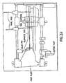
Figs. 2A-2K show implantation of an ankle prosthesis according to an embodiment of the present invention; and -
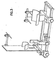
Fig. 3 shows instrumentation according to another embodiment of the present invention. - Among those benefits and improvements that have been disclosed, other objects and advantages of this invention will become apparent from the following description taken in conjunction with the accompanying figures. The figures constitute a part of this specification and include an illustrative embodiment of the present invention and illustrate various objects and features thereof.
- Detailed embodiments of the present invention are disclosed herein; however, it is to be understood that the disclosed embodiments are merely illustrative of the invention that may be embodied in various forms. In addition, each of the examples given in connection with the various embodiments of the invention are intended to be illustrative, and not restrictive. Further, the figures are not necessarily to scale, some features may be exaggerated to show details of particular components. Therefore, specific structural and functional details disclosed herein are not to be interpreted as limiting, but merely as a representative basis for teaching one skilled in the art to variously employ the present invention.
- In one embodiment an ankle prosthesis according to the present invention minimizes edge loading by using bicondylar articular geometry which enhances varus/valgus stability while maintaining an appropriately central load distribution within the prosthesis. In this regard, it is believed that in combination with adequate bone coverage of the resected bones by the prosthesis, an appropriately central load distribution would minimize prosthesis subsidence into the bone (by minimizing bone stress). Such a bicondylar geometry may allow the achievement of varus/valgus stability by shifting the joint compressive load center medially or laterally upon the joint contact surface, but prevents the joint compression load center from reaching the edge of the contact surface. An appropriate mechanism for varus/valgus stability may incorporate the shifting of the joint contact load from the medial to the lateral bicondylar surface for moderate varus/valgus loads and augmenting this stability mechanism with tensile loads in the collateral ligaments spanning the ankle joint. To produce collateral ligament loads, it may be necessary to stretch the ligaments and hence allow the opening of either the medial or the lateral condylar surfaces. By use of full radii of curvature of the medial and lateral bicondylar surfaces this embodiment may allow varus/valgus angulation to the extent of approximately, for example (which example is intended to be illustrative and not restrictive) three to five degrees, while maintaining essentially full central contact within either the medial or lateral condyle. This allows the required contact load shifting and stretching of the appropriate collateral ligament without significant edge loading. In another example (which example is intended to be illustrative and not restrictive), the angulation may be one to ten degrees.
- In another embodiment an ankle prosthesis according to the present invention utilizes articular surface(s) with conical shape(s) which operate to couple the flexion/extension and inversion/eversion (it is believed that a contributing factor to a stable gait and proper foot/ground contact pattern is the coupling between the flexion/extension mechanism and the inversion/eversion motion normally present in the ankle joint).
- In another embodiment an ankle prosthesis according to the present invention utilizes a design that: (a) in extreme dorsiflexion provides a maximized plantarflexion moment arm; and (b) in extreme plantarflexion provides a maximized dorsiflexion moment arm. This may be accomplished by choosing appropriate radii of curvature for one or more articular surfaces (e.g., so as to allow approximately, for example (which example is intended to be illustrative and not restrictive), two or three millimeters of anterior/posterior translation of the tibial and talar components). In another example (which example is intended to be illustrative and not restrictive), one to five millimeters of anterior/posterior translation of the tibial and talar components may be provided.
- In another embodiment an ankle prosthesis utilizes a design that provides for the "contact point" or center of contact pressure to move anteriorly with dorsiflexion and posteriorly with plantarflexion (e.g., to achieve an acceptable range of motion by allowing the ankle joint to follow the biomechanical principle that, in extreme positions of motion, the muscle group with the more favorable moment arm is that group which opposes the extreme motion.
- Of note, conventional ankle joint prostheses typically attempt to achieve low contact stress and low wear by using either fully congruent contact surfaces, such as found in mobile bearings, or so called flat-on-flat designs that provide cylindrical articulating surfaces. While various embodiments of the present invention provide the above described bicondylar geometry, the above described coupled flexion/extension and inversion/eversion motion and the above described anterior/posterior translation of the center of the joint contact surface, the present invention combines these three features in such a way so as to avoid either fully congruent articular surfaces or line to line contact articular surfaces (i.e., an embodiment of the present invention utilizes articular surfaces that are not fully congruent in the anterior/posterior direction or the medial/lateral direction). More particularly, the surface geometry is comprised of circle arcs. These arcs form both the medial/lateral and anterior/posterior contours of the tibio-talar articulating surface. Moreover, in the medial/lateral direction, these radii overlie a conical section. In particular, the ratio of the talar component radii of curvature of both medial and lateral bicondylar surfaces, in the medial/lateral direction, is between 92% and 96% of the corresponding tibial component radii of curvature of both medial and lateral bicondylar surfaces.
- Of further note, an ankle joint is composed of three articulating surfaces: tibial/talar articulation, medial malleolus/talar articulation, and lateral malleolus/talar articulation. Conventional ankle prostheses typically do not allow the surgeon to choose, at the time of surgery, which of these three joint surfaces will be replaced (it is believed that some conventional prostheses provide only a hemiarthroplasty on the medial and lateral sides). This is a potential source of impingement or pain from articulation of the arthritic joint surface against the metal surface. While it is true that this is not necessarily a concern in all the patients, many of whom may have minimal arthritic changes in the medial or lateral gutters, it may be desirable to provide flexibility at the time of surgery according to an embodiment of the present invention (e.g., so that if the surgeon identifies arthritis in the medial or lateral gutter, a total joint replacement rather than hemiarthroplasty can be performed).
- An ankle replacement, implant procedure, and implant instrumentation are herein described which: 1) do not sacrifice too much bone (which excess sacrifice could make revision of the implant and/or conversion to a fusion difficult); 2) do not place the implant on relatively weak bone (which could encourage subsidence,); 3) do not allow excessive loosening of the implant from poor fixation; and 4) do not result in a significant incidence of wound problems.
- An ankle prosthesis may include an element (e.g., a button with an articular surface (e.g., a spherical or spheroidal shaped articular surface)) that can be placed on either or both malleolar articulating surfaces to form an articular interface with lateral surfaces of the talar component (or any biomechanical axis). In one example (which example is intended to be illustrative and not restrictive), this feature may provide the surgical option of resurfacing one or both of the medial and lateral gutters (e.g., which lateral gutter may comprise a lateral fibula and talar articular surface)).
- Referring now to
Figs. 1A-1E , an ankle prosthesis according to an embodiment of the present invention is shown. - Referring now to surgical methods (and corresponding instrumentation) which may be used to implant the ankle prosthesis, it is noted that the invention may be utilized, for example, in the context of an anterior approach, a lateral approach, a combined lateral and medial approach, or a combination of a lateral and anteromedial approach.
- In any case, referring now to
Figs2A-2K , implantation steps of an ankle prosthesis according to an embodiment of the present invention may be as follows: - 1) Do a lateral approach, fibular osteotomy and exposure of the joint.
- 2) Attach two pins to the tibia and one to the medial talus.
- 3) With use of fluoroscopy, adjust the alignment of the tibia and lock this so that the shaft of the tibia is parallel to the radiopaque rod in the alignment jig.
- 4) Strap the foot on the clear foot plate.
- 5) Adjust the cutter pivot assembly to allow a side cutting instrument (e.g., drill) to arc the outer surface of the tibial component from the tibia. This device allows prox-distal adjustment and anterior/posterior adjustment. A set of pivot guides may be associated with each size of implant, that is, for a small implant there may be a smaller radius of curvature. The guides may also have stops to avoid overreaching with the side cutting bit.
- 6) After the appropriate amount of bone is remove from the tibia (e.g., enough to allow proper positioning of the foot-with the calcaneus in neutral position) attention is directed to the talar side.
- 7) The foot plate is positioned so the plantar aspect of the entire foot is perpendicular to the tibia. The translucent plate on which the foot is secured allows the surgeon to be absolutely sure the heel and metatarsals all are in contact.
- 8) The superior dome of the talus is then side cut with the same pivot guide assembly.
- 9) Trial spacers are placed to ensure parallelism of the cuts, and no overtensioning of the deltoid.
- 10) The spacers may have lateral slots for drilling the ridge holes and overhangs through which pins are temporarily placed to secure the guide for the ridge holes.
- 11) One or two lateral-medial ridge hole(s) are drilled adjacent to the exposed cut surface of the distal tibia and one or two others are drilled in the superior surface of the proximal talus.
- 12) Trial tibial and talar components are placed and again the deltoid tightness is assessed. If needed more bone is removed with the side cutting instrument (e.g., drill) and pivot guide.
- 13) Occasionally, the surgeon may make an anteromedial incision to remove bone from the medial side of the joint (the surgeon may decide to use the same implant with a medial and/or lateral overhang to the talar component). The surgeon may also decide to use a cemented polyethylene button on the medial side of the fibula.
- 14) The lateral side is then adjusted in a superior/inferior direction to maintain ligament tension on the calcaneal-fibutar ligament.
- 15) The lateral fibula is fixated with standard orthopaedic hardware such as a plate and/or screw, tension band technique or intramedulary device.
- In another example in connection with step (2) above, the surgeon may have the option of not only placing a pin in the talus but also in the calcaneus.
- In another example, step (7) above may be combined with the step (4) above, such that step (4) includes both elements (i.e., strapping the foot on the clear foot plate and positioning the foot plate.
- Other surgical methods and corresponding instrumentation include:
- Anterior Approach
- o Technique
- ■ In the anterior approach according to one embodiment a straight incision may be used (e.g., to minimize wound problems). The dissection may be carried through the extensor hallucis longus sheath with the EHL tendon retracted medially and the neurovascular bundle retracted laterally (this leaves the blood supply to the extensor digitorum brevis intact for the possible use in a flap in care of a wound problem).
- ■ The tibial bone cut may be made from a cutting block which may be set essentially parallel to the floor when the foot is in a plantigrade position on both the AP view and perpendicular to the midlongitudinal axis of the tibia on the lateral view. Fluoroscopy may be used to determine the position of the cutting block so that a minimal amount of bone will be resected with the proper alignment. In one example (which example is intended to be illustrative and not restrictive) some patients may be treated using a guide system based on the plane of the sole of the foot that will allow cuts to be made parallel to this plane in the tibia and the superior portion of the talus. For the top portion of the talar cut an extension to the tibia cutting block may be used. The front and back or the side cuts may be performed next. For the front and back cuts, a different cutting block may be attached to the talus. For the side cuts, the same cutting block or a third cutting block referenced to the talus may be used. Once the cuts are completed, both the tibia and talar trial components may be placed and range of motion and ligament laxity/tightness determined. Finally, ligament balancing may be performed to help insure proper ligament tension both medially and laterally without excessive laxity or tightness in the ligaments. In another example (which example is intended to be illustrative and not restrictive) instrumentation stops may be available for some or all cuts used and/or appropriate design features may be incorporated to make it difficult to cut beyond a desired range (e.g., in the area of the posterior aspect of the tibia where injury to tendons and nerves are possible; tendon lacerations from such cuts have occurred in total ankle replacements).
- o Instrumentation
- ■ The instrumentation may include a cutting block for the distal tibial cut attached to a long rod secured to the proximal leg. This block may be designed to permit fine adjustments superior-inferior, medial lateral, and may have a capture mechanism for the saw blade. The cutting block may be placed under fluoroscopic control. In one example (which example is intended to be illustrative and not restrictive) 2 pins in the tibia may be used for fixation. In this case, the first pin may be placed with consideration of internal-external rotation. Afterward the varus-valgus position may be determined, for example, by fluoroscopic imaging and/or from the plane of the sole of the foot and the second pin may be placed. Next the extension-flexion position for the lateral X-ray image may be determined and when the position of the block permits a cut perpendicular to the mid-longitudinal axis of the tibia the height of the tibial rod may be secured at the level of the proximal tibia. The height of the'cut may be fine-tuned at the cutting block. The AP view may be repeated and the medial-lateral extent of the cut may then adjusted and locked in. The saw may have a stop to reduce possibility of injury to vital posterior soft tissue structures. After this cut is made, the talus may be positioned in all three planes and a block extension may be used to remove the superior surface.
- ■ The instrumentation may include right and left guides for making the posterior, anterior, and medial/lateral cuts on the talus. In addition, the invention may employ a guide for cutting the corresponding surfaces of the malleoli and placing a slot for the buttons (e.g., poly buttons).
- o Technique
- Lateral Approach
- o Technique
- ■ The advantages of this approach (relative to the anterior approach) may include: 1) less bone resection; 2) essentially complete access to the lateral joint space; 3) ability to perform a controlled release of chronically tight posterior ankle and/or subtalar joint ligaments; 4) decreased risk of tendon and/or nerve lacerations with the ability to place retractors on the posterior tibia; and 5) likely decreased incidence of wound complications. In addition, this lateral approach offers the possibility to perform one or more curved cuts and/or one or more flat cuts close to a curved cut on both of these articular surfaces (i.e., the distal tibial and proximal talar). Such curved cuts and/or one or more flat cuts close to a curved cut may aid in minimizing bone resection, thereby retaining the periankle bone stock (which is a particularly strong bone for stress transfer). Curved or nearly curved surfaces with minimal bone resection should allow for a greater area of coverage of this stronger bone.
- ■ To have access to the ankle, the lateral side of the fibula is osteotomized. The distal fibular fragment may be reflected posteriorly, after incising the anterior talofibular ligament (which may be repaired at the end of the procedure). The fibula osteotomy may be later fixed with screws and/or plate and/or other fixation. at the end of the procedure. In one example (which example is intended to be illustrative and not restrictive) bone cuts may be made by an oscillating curved saw blade for the curved talar and/or tibial cuts or alternatively flat cuts but with minimal bone resection. These cuts may be aligned by bony landmarks and/or off an alignment guide. K wires may be placed and checked fluroscopically and used to fix the alignment guides and/or guide the bone cuts. The described approach may give access to the lateral joint surface of the talus and the medial aspect of the lateral malleoulus. One or both of these surfaces may be prepared for resurfacing from this approach.
- ■ To gain adequate access to the medial joint surface when a transfibular approach is used, a separate incision may be made on the anteromedial side of the ankle joint. Through the anteromedial and lateral incisions any anterior osteophytes may be removed. This approach may allow resurfacing of the medial aspect of the talus, the lateral aspect of the medial malleolus and controlled cutting of the tibia and talus from the lateral side. From the anteromedial incision either an osteotome may be placed along the superior medial gutter into the tibia or pins may be used to block the progress of the saw blade and prevent cutting the medial malleolus when the cuts are made from lateral to medial. If curved cuts are used the extent of the curve anteriorly and posteriorly may likely be slightly more than that of the ankle prosthesis. From the lateral approach one or more small slot cuts for initial fixation of the implant(s) may be made. In one example (which example is intended to be illustrative and not restrictive) these slot cuts(s) may be done with a drill directly through the joint line to simultaneously produce a slot into the tibia and talus. This may correspond to a small peg on the tibial and/or talar trials and/or implants to guide insertion and maintain alignment. From the medial approach, when needed, the surgeon may prepare the medial aspect of the talus and/or the lateral aspect of the medial malleolus for implant fixation.
- o Instrumentation
- ■ If curved cuts are to be used, an oscillating saw, drill, burr, and/or router may, in one example (which example is intended to be illustrative and not restrictive), be employed to make such cut(s). On the tibial side, pin(s) may be placed under fluoroscopic guidance to define the plane of the cut. In the AP projection, this pin may be placed to lock in the varus-valgus and internal-external rotation position of the tibial tray. In one example (which example is intended to be illustrative and not restrictive) a cutting saw that is curved with an attached guidance slot for the pin may be used. For positioning of the talar cut a pin may be used perpendicular to the side of the talus or somewhat off this perpendicular according to the alignment of the cone, or the cut may be made off the pin already inserted in the tibia after the talus has been held in the correct amount of varus-valgus and internal-external rotation by the surgical team. For the tibial and talar guides an alignment cutting block may be used. In one example (which example is intended to be illustrative and not restrictive) the cuts for the pegs may be made with the drill, router, or small saw to simultaneously make the slots for the talar and tibial components. This may be done in one of many ways known to those of ordinary skill in the art. Trials with undersized pegs for the slots can then be applied. Trials may be used to judge alignment, adequate range of motion without impingement and ligament tension.
- ■ A separate guide for the medial and lateral cuts on the talus may be used to assure proper width of the talus to fit the implant. In one example (which example is intended to be illustrative and not restrictive) it is likely that after the top talar cut, the lateral cut will be made on the talus. A guide on the top of the talar may then be used to make a corresponding medial cut through the anteromedial incision, and lateral cut through the transfibular approach. This may be done in a reverse order. The medial cut may be made as described for the anterior technique. The lateral cut may be made with a cutout along the lateral joint surface (e.g., that is cleared by a side cutting drill bit with a depth stop). The medial surface of the lateral malleolus may be prepared as a standard patellar resurfacing to allow a cemented button (e.g., poly button) to be placed. The lateral surface of the medial malleolus may be prepared with a saw cut and placement of a slot for the button peg.
- o Technique
- Referring now to
Fig. 3 , instrumentation is shown. - The instrumentation may be made to align the cuts according to bony landmarks and/or fluoroscopic control.
- The guides for the cutting may be fixed to an external fixator, and/or be fixed directly to the bone, and/or be based on a guidance system (e.g., from the plane of the sole of the foot). The aforementioned configurations may be used for purposes of overall alignment and stability.
- Some or all of the instrumentation may be made so as to be used on the right and left ankles (i.e., all of the instrumentation may be made so as to be used on the right and left ankles or there may be some separate instrumentation for the right and/or left sides).
- An ankle replacement may be shaped to conform to the curvilinear shape of the bones which comprise the ankle.
- Cuved as well as straight cuts may be used to prepare the bony surfaces for implantation (e.g., in order to sacrifice less bone as compared to straight cuts alone).
- An ankle replacement may be inserted through a lateral and medial approach (the implant may, of course, be inserted using another approach (e.g., an anterior approach).
- Revision tibial and talar implants with threaded (e.g., male) fixation peg(s) on the surface facing the bone may be used with a variety of differently sized (e.g., length, width and/or shape) interchangeable (e.g., female) fixation devices.
- An ankle replacement may be composed of metal, ceramic, an ultra high molecular weight polyethylene plastic and/or a tantalum mesh.
- An ankle prosthesis may be provided in which at least one component (e.g., a tibial component) includes a polymer plastic bearing surface (e.g., ultra high molecular weight polyethylene (UHMWPE)), wherein the bearing surface is integrally attached to a metal and/or ceramic backing plate. This plate may contain an appropriate surface for interfacing with and attaching to bone. Further, this interface surface may be of a porous nature to allow bone ingrowth. Further still, malleolar components may be universal. These components may use mechanical attachment with a bone-cement interface and/or an appropriate porous metal backing to allow fixation to the bone.
- The polyethylene articular surfaces may be produced by direct compression molding (a process that provides enhanced aging resistance and wear resistance).
- A method of attachment between the polyethylene bearing surface and the metal backing may utilize direct compression molding of the articular surface onto the metal backing (with interlocking provided by any of the methods known to those of ordinary skill in the art (e.g., undercuts and/or porous surface penetration).
- A system of implant(s) to accommodate the special requirements of revision surgery (and/or conversion to a fusion may be provided. Revision problems such as, for example, subsidence and bone loss, subluxation and possible dislocation may be addressed by this embodiment. In the event such problems should occur (or to revise other total ankle replacements), revision implants may be provided. For dislocation or subluxation the ability to revise the bone cuts so the joint will not sublux may be necessary and provided for. In this instance (as well as the instance of significant bone loss), augmentation of bone stock may be allowed for. The use of bone substitutes and/or bone graft with bone substitutes may be possible. Design features such as metal peg(s) screwed into the revision prosthesis and/or slot(s) and/or fin(s) may be used. These design features may articulate with the patient's bone to assist in fixation (e.g., of the bone graft to the patient's bone and the implant).
- The present invention lends itself directly to computer navigational and/or robotic implantation. For example, use of a navigational system may help insure proper alignment of the foot versus the tibia in judging things such as heel valgus and foot position versus the tibia. Further, it is noted that an embodiment of the present invention may require cutting mechanism(s) be attached to the tibia in a way that allows direct (e.g., through the fixator setup) distraction of the joint with the cutting guides attached to the fixator.
- In another example, an element may be a curved or nearly curved shape on the bone side of the tibial and talar components. These may be curved cuts or nearly so using a series of flats cuts to take minimal bone.
- In another example, an element may be the external fixating jig for alignment and the tibial and talar bone cuts which are used for the purpose of alignment.
- In another example, an element may be the fixation of the whole jig to the tibia as well as to the foot.
- In another example, the prosthesis may include a medial-lateral ridge.
- In another example, the prosthesis may maintain stability with little or no edge evolving.
- While a number of embodiments of the present invention have been described, it is understood that these embodiments are illustrative only, and not restrictive, and that many modifications may become apparent to those of ordinary skill in the art. For example, the steps described in connection with the surgical procedures (and/or any assembly/manufacturing) may be carried out in any desired order, some steps may be omitted, and/or other steps may be added. Further, some of the instrumentation described herein may not be utilized and/or additional instrumentation may be employed. Further still, the ankle prosthesis may include left sided and right sided components (e.g., tibial and talar components). Of note, such left sided and right sided components may be used, in one embodiment, due to a conical component of the articular geometry. Further still, the apparatus (and/or its components) may, of course, have any desired dimensions (e.g., for any desired patient - man, woman or child). Further still, the apparatus (and/or its components) may be provided in a "line" or "family" of devices (e.g., small, medium and large; adult, child; male, female). Further still, the apparatus (and/or its components) may be provided in standard sizes.
Claims (11)
- An ankle prosthesis, comprising:a tibial component for attachment to a tibia, wherein the tibial component has first and second surfaces; anda talar component for attachment to a talus, wherein the talar component has first and second surfaces;wherein at least a portion of the first surface of the tibial component is configured to be disposed adjacent the tibia;wherein at least a portion of the first surface of the talar component is configured to be disposed adjacent the talus;wherein at least a portion of the second surface of the tibial component and at least a portion of the second surface of the talar component are configured to form an articulation interface between the tibial component and the talar component;wherein the articulation interface includes a bicondylar geometry such that each of a. medial side and a lateral side of the second surface of the tibial component includes a curved contour and each of a medial side and a lateral side of the second surface of the talar component includes a curved contour; and characterised in thatthe ratio of the radii of curvature of both the medial side and lateral side of the second surface of the talar component in the mediaviateral direction is between 92% and 96% of the corresponding radii of curvature of the medial side and lateral side of the second surface of the tibial component.
- The ankle prosthesis of claim 1, wherein each curved contour of the medial and lateral sides of the second surface of the tibial component is concave and each curved contour of the medial and lateral sides of the second surface of the talar component is convex.
- The ankle prosthesis of claim 1, wherein each curved contour of the medial and lateral sides of the second surface of the tibial component is convex and each curved contour of the medial and lateral sides of the second surface of the talar component is concave.
- The ankle prosthesis according to any preceding claim, wherein the ankle prosthesis is configured to be implanted by a lateral transfibular approach.
- The ankle prosthesis according to any preceding claim, wherein the ankle prosthesis is configured such that implantation may be carried out while retaining the periankle bone stock.
- The ankle prosthesis according to any preceding claim, wherein the articulation interface comprises a fixed bearing.
- The ankle prosthesis according to any preceding claim, wherein the ankle prosthesis is configured to be fixed primarily via bone growth.
- The ankle prosthesis according to any preceding claim, further comprising a button with an articulation surface, wherein the button is attached to a fibula.
- The ankle prosthesis of claim 8, wherein the articulation surface is selected from the group including a spherical shaped surface and a spheroidal shaped surface.
- The ankle prosthesis according to any preceding claim, wherein the ankle prosthesis is configured to be fixed without resurfacing a lateral gutter.
- The ankle prosthesis according to any of claims 1-9, wherein the ankle prosthesis is configured to be fixed by resurfacing at least a part of a lateral gutter.
Applications Claiming Priority (2)
| Application Number | Priority Date | Filing Date | Title |
|---|---|---|---|
| US51088703P | 2003-10-14 | 2003-10-14 | |
| PCT/US2004/033913 WO2005037135A2 (en) | 2003-10-14 | 2004-10-14 | Ankle prosthesis and method for implanting ankle prosthesis |
Publications (3)
| Publication Number | Publication Date |
|---|---|
| EP1677709A2 EP1677709A2 (en) | 2006-07-12 |
| EP1677709A4 EP1677709A4 (en) | 2007-10-31 |
| EP1677709B1 true EP1677709B1 (en) | 2012-02-01 |
Family
ID=34465161
Family Applications (1)
| Application Number | Title | Priority Date | Filing Date |
|---|---|---|---|
| EP04795116A Not-in-force EP1677709B1 (en) | 2003-10-14 | 2004-10-14 | Ankle prosthesis |
Country Status (5)
| Country | Link |
|---|---|
| US (4) | US7625409B2 (en) |
| EP (1) | EP1677709B1 (en) |
| JP (1) | JP4567686B2 (en) |
| AT (1) | ATE543464T1 (en) |
| WO (1) | WO2005037135A2 (en) |
Families Citing this family (145)
| Publication number | Priority date | Publication date | Assignee | Title |
|---|---|---|---|---|
| US7635390B1 (en) | 2000-01-14 | 2009-12-22 | Marctec, Llc | Joint replacement component having a modular articulating surface |
| US7708741B1 (en) | 2001-08-28 | 2010-05-04 | Marctec, Llc | Method of preparing bones for knee replacement surgery |
| US9155544B2 (en) | 2002-03-20 | 2015-10-13 | P Tech, Llc | Robotic systems and methods |
| ATE454110T1 (en) * | 2003-06-27 | 2010-01-15 | Abs Corp | SYSTEM FOR ANKLE JOINT ARTHROPLASTY |
| WO2005030098A1 (en) | 2003-08-27 | 2005-04-07 | Waldemar Link Gmbh & Co. Kg | Ankle-joint endoprosthesis |
| EP1677709B1 (en) * | 2003-10-14 | 2012-02-01 | University Of Iowa Research Foundation | Ankle prosthesis |
| AU2006223238B2 (en) * | 2005-03-14 | 2011-09-29 | Inbone Technologies, Inc. | Ankle replacement system |
| EP1981439A4 (en) * | 2006-01-20 | 2013-02-06 | Gmbh Synthes | Method of preparing an ankle joint for replacement, joint prosthesis, and cutting alignment apparatus for use in performing an arthroplasty procedure |
| US9173661B2 (en) | 2006-02-27 | 2015-11-03 | Biomet Manufacturing, Llc | Patient specific alignment guide with cutting surface and laser indicator |
| US8608748B2 (en) | 2006-02-27 | 2013-12-17 | Biomet Manufacturing, Llc | Patient specific guides |
| US8298237B2 (en) | 2006-06-09 | 2012-10-30 | Biomet Manufacturing Corp. | Patient-specific alignment guide for multiple incisions |
| US8133234B2 (en) | 2006-02-27 | 2012-03-13 | Biomet Manufacturing Corp. | Patient specific acetabular guide and method |
| US8241293B2 (en) | 2006-02-27 | 2012-08-14 | Biomet Manufacturing Corp. | Patient specific high tibia osteotomy |
| US9339278B2 (en) | 2006-02-27 | 2016-05-17 | Biomet Manufacturing, Llc | Patient-specific acetabular guides and associated instruments |
| US7967868B2 (en) | 2007-04-17 | 2011-06-28 | Biomet Manufacturing Corp. | Patient-modified implant and associated method |
| US9918740B2 (en) | 2006-02-27 | 2018-03-20 | Biomet Manufacturing, Llc | Backup surgical instrument system and method |
| US8568487B2 (en) | 2006-02-27 | 2013-10-29 | Biomet Manufacturing, Llc | Patient-specific hip joint devices |
| US8092465B2 (en) | 2006-06-09 | 2012-01-10 | Biomet Manufacturing Corp. | Patient specific knee alignment guide and associated method |
| US9345548B2 (en) | 2006-02-27 | 2016-05-24 | Biomet Manufacturing, Llc | Patient-specific pre-operative planning |
| US20150335438A1 (en) | 2006-02-27 | 2015-11-26 | Biomet Manufacturing, Llc. | Patient-specific augments |
| US10278711B2 (en) | 2006-02-27 | 2019-05-07 | Biomet Manufacturing, Llc | Patient-specific femoral guide |
| US8603180B2 (en) | 2006-02-27 | 2013-12-10 | Biomet Manufacturing, Llc | Patient-specific acetabular alignment guides |
| US8535387B2 (en) | 2006-02-27 | 2013-09-17 | Biomet Manufacturing, Llc | Patient-specific tools and implants |
| US8407067B2 (en) | 2007-04-17 | 2013-03-26 | Biomet Manufacturing Corp. | Method and apparatus for manufacturing an implant |
| US9289253B2 (en) | 2006-02-27 | 2016-03-22 | Biomet Manufacturing, Llc | Patient-specific shoulder guide |
| US8282646B2 (en) | 2006-02-27 | 2012-10-09 | Biomet Manufacturing Corp. | Patient specific knee alignment guide and associated method |
| US8591516B2 (en) | 2006-02-27 | 2013-11-26 | Biomet Manufacturing, Llc | Patient-specific orthopedic instruments |
| US8864769B2 (en) | 2006-02-27 | 2014-10-21 | Biomet Manufacturing, Llc | Alignment guides with patient-specific anchoring elements |
| US8070752B2 (en) | 2006-02-27 | 2011-12-06 | Biomet Manufacturing Corp. | Patient specific alignment guide and inter-operative adjustment |
| US9113971B2 (en) | 2006-02-27 | 2015-08-25 | Biomet Manufacturing, Llc | Femoral acetabular impingement guide |
| US8858561B2 (en) | 2006-06-09 | 2014-10-14 | Blomet Manufacturing, LLC | Patient-specific alignment guide |
| US8473305B2 (en) | 2007-04-17 | 2013-06-25 | Biomet Manufacturing Corp. | Method and apparatus for manufacturing an implant |
| US8377066B2 (en) | 2006-02-27 | 2013-02-19 | Biomet Manufacturing Corp. | Patient-specific elbow guides and associated methods |
| US9907659B2 (en) | 2007-04-17 | 2018-03-06 | Biomet Manufacturing, Llc | Method and apparatus for manufacturing an implant |
| US8608749B2 (en) | 2006-02-27 | 2013-12-17 | Biomet Manufacturing, Llc | Patient-specific acetabular guides and associated instruments |
| US9795399B2 (en) | 2006-06-09 | 2017-10-24 | Biomet Manufacturing, Llc | Patient-specific knee alignment guide and associated method |
| US8265949B2 (en) | 2007-09-27 | 2012-09-11 | Depuy Products, Inc. | Customized patient surgical plan |
| US8357111B2 (en) | 2007-09-30 | 2013-01-22 | Depuy Products, Inc. | Method and system for designing patient-specific orthopaedic surgical instruments |
| ES2838598T3 (en) | 2007-09-30 | 2021-07-02 | Depuy Products Inc | Customized, patient-specific orthopedic surgical instrument |
| WO2009153071A2 (en) * | 2008-05-29 | 2009-12-23 | Tornier | Surgical device for immobilizing a patient's operated-on ankle |
| AU2009262113A1 (en) | 2008-06-25 | 2009-12-30 | Small Bone Innovations, Inc. | Surgical instrumentation and methods of use for implanting a prothesis |
| US8257357B2 (en) * | 2008-09-23 | 2012-09-04 | Edwin Burton Hatch | Combination of a motor driven oscillating orthopedic reshaping and resurfacing tool and a surface-matching sheet metal prosthesis |
| US8170641B2 (en) | 2009-02-20 | 2012-05-01 | Biomet Manufacturing Corp. | Method of imaging an extremity of a patient |
| WO2010122034A1 (en) * | 2009-04-21 | 2010-10-28 | Tornier | Foot positioning system and method |
| DE102009028503B4 (en) | 2009-08-13 | 2013-11-14 | Biomet Manufacturing Corp. | Resection template for the resection of bones, method for producing such a resection template and operation set for performing knee joint surgery |
| US8292954B2 (en) * | 2009-09-11 | 2012-10-23 | Articulinx, Inc. | Disc-based orthopedic devices |
| US8206072B2 (en) * | 2009-10-12 | 2012-06-26 | Zimmer, Inc. | Quick release nut |
| WO2011072249A1 (en) | 2009-12-11 | 2011-06-16 | Small Bone Innovations, Inc. | Ankle fusion device, instrumentation and methods |
| US8632547B2 (en) | 2010-02-26 | 2014-01-21 | Biomet Sports Medicine, Llc | Patient-specific osteotomy devices and methods |
| US8303667B2 (en) | 2010-03-02 | 2012-11-06 | Alastair Younger | Fastening system for prostheses |
| US9066727B2 (en) | 2010-03-04 | 2015-06-30 | Materialise Nv | Patient-specific computed tomography guides |
| US9271744B2 (en) | 2010-09-29 | 2016-03-01 | Biomet Manufacturing, Llc | Patient-specific guide for partial acetabular socket replacement |
| US8668743B2 (en) | 2010-11-02 | 2014-03-11 | Adam D. Perler | Prosthetic device with multi-axis dual bearing assembly and methods for resection |
| US8597361B2 (en) | 2010-11-11 | 2013-12-03 | Bioshift, Llc | Joint implant fixation system |
| US8961519B2 (en) | 2010-11-19 | 2015-02-24 | Zimmer, Inc. | Surgical rotary cutting tool and tool guard assembly |
| US9968376B2 (en) | 2010-11-29 | 2018-05-15 | Biomet Manufacturing, Llc | Patient-specific orthopedic instruments |
| AU2016244327B2 (en) * | 2010-12-20 | 2018-04-05 | Microport Orthopedics Holdings Inc. | Orthopedic surgical guide |
| FR2971144A1 (en) | 2011-02-08 | 2012-08-10 | Tornier Sa | GLENOIDAL IMPLANT FOR SHOULDER PROSTHESIS AND SURGICAL KIT |
| US9241745B2 (en) | 2011-03-07 | 2016-01-26 | Biomet Manufacturing, Llc | Patient-specific femoral version guide |
| US9186154B2 (en) | 2011-03-17 | 2015-11-17 | Zimmer, Inc. | Patient-specific instruments for total ankle arthroplasty |
| US8715289B2 (en) | 2011-04-15 | 2014-05-06 | Biomet Manufacturing, Llc | Patient-specific numerically controlled instrument |
| US9675400B2 (en) | 2011-04-19 | 2017-06-13 | Biomet Manufacturing, Llc | Patient-specific fracture fixation instrumentation and method |
| US8956364B2 (en) | 2011-04-29 | 2015-02-17 | Biomet Manufacturing, Llc | Patient-specific partial knee guides and other instruments |
| US8668700B2 (en) | 2011-04-29 | 2014-03-11 | Biomet Manufacturing, Llc | Patient-specific convertible guides |
| US8532807B2 (en) | 2011-06-06 | 2013-09-10 | Biomet Manufacturing, Llc | Pre-operative planning and manufacturing method for orthopedic procedure |
| US9084618B2 (en) | 2011-06-13 | 2015-07-21 | Biomet Manufacturing, Llc | Drill guides for confirming alignment of patient-specific alignment guides |
| US8764760B2 (en) | 2011-07-01 | 2014-07-01 | Biomet Manufacturing, Llc | Patient-specific bone-cutting guidance instruments and methods |
| US20130001121A1 (en) | 2011-07-01 | 2013-01-03 | Biomet Manufacturing Corp. | Backup kit for a patient-specific arthroplasty kit assembly |
| EP2734168B1 (en) | 2011-07-22 | 2015-09-16 | Stryker Corporation | Multi-position limb holder |
| US8597365B2 (en) | 2011-08-04 | 2013-12-03 | Biomet Manufacturing, Llc | Patient-specific pelvic implants for acetabular reconstruction |
| US9066734B2 (en) | 2011-08-31 | 2015-06-30 | Biomet Manufacturing, Llc | Patient-specific sacroiliac guides and associated methods |
| US9295497B2 (en) | 2011-08-31 | 2016-03-29 | Biomet Manufacturing, Llc | Patient-specific sacroiliac and pedicle guides |
| US9386993B2 (en) | 2011-09-29 | 2016-07-12 | Biomet Manufacturing, Llc | Patient-specific femoroacetabular impingement instruments and methods |
| KR20130046336A (en) | 2011-10-27 | 2013-05-07 | 삼성전자주식회사 | Multi-view device of display apparatus and contol method thereof, and display system |
| US9451973B2 (en) | 2011-10-27 | 2016-09-27 | Biomet Manufacturing, Llc | Patient specific glenoid guide |
| US9554910B2 (en) | 2011-10-27 | 2017-01-31 | Biomet Manufacturing, Llc | Patient-specific glenoid guide and implants |
| EP2770918B1 (en) | 2011-10-27 | 2017-07-19 | Biomet Manufacturing, LLC | Patient-specific glenoid guides |
| US9301812B2 (en) | 2011-10-27 | 2016-04-05 | Biomet Manufacturing, Llc | Methods for patient-specific shoulder arthroplasty |
| FR2986415A1 (en) | 2012-02-06 | 2013-08-09 | Tornier Sa | SURGICAL INSTRUMENTATION ASSEMBLY FOR POSTING AN ANKLE PROSTHESIS |
| US9237950B2 (en) | 2012-02-02 | 2016-01-19 | Biomet Manufacturing, Llc | Implant with patient-specific porous structure |
| US9295554B2 (en) | 2012-07-10 | 2016-03-29 | Zimmer, Inc. | Attachments for orthopedic implants |
| US9750613B2 (en) | 2012-11-12 | 2017-09-05 | Wright Medical Technology, Inc. | Stabilized total ankle prosthesis |
| US9204977B2 (en) | 2012-12-11 | 2015-12-08 | Biomet Manufacturing, Llc | Patient-specific acetabular guide for anterior approach |
| US9060788B2 (en) | 2012-12-11 | 2015-06-23 | Biomet Manufacturing, Llc | Patient-specific acetabular guide for anterior approach |
| US10080573B2 (en) | 2012-12-27 | 2018-09-25 | Wright Medical Technology, Inc. | Ankle replacement system and method |
| US9974588B2 (en) | 2012-12-27 | 2018-05-22 | Wright Medical Technology, Inc. | Ankle replacement system and method |
| US9918724B2 (en) | 2012-12-27 | 2018-03-20 | Wright Medical Technology, Inc. | Ankle replacement system and method |
| AU2013270628B2 (en) * | 2012-12-27 | 2015-02-05 | Wright Medical Technology, Inc. | Ankle replacement system and method |
| US9480571B2 (en) | 2012-12-27 | 2016-11-01 | Wright Medical Technology, Inc. | Ankle replacement system and method |
| US9839438B2 (en) | 2013-03-11 | 2017-12-12 | Biomet Manufacturing, Llc | Patient-specific glenoid guide with a reusable guide holder |
| US9579107B2 (en) | 2013-03-12 | 2017-02-28 | Biomet Manufacturing, Llc | Multi-point fit for patient specific guide |
| US9949839B2 (en) | 2013-03-13 | 2018-04-24 | Wright Medical Technology, Inc. | Revision implant augments, systems, and methods |
| US9826981B2 (en) | 2013-03-13 | 2017-11-28 | Biomet Manufacturing, Llc | Tangential fit of patient-specific guides |
| US9498233B2 (en) | 2013-03-13 | 2016-11-22 | Biomet Manufacturing, Llc. | Universal acetabular guide and associated hardware |
| AU2014239584B2 (en) | 2013-03-14 | 2017-11-02 | Wright Medical Technology, Inc. | Ankle replacement system and method |
| WO2014149952A1 (en) | 2013-03-15 | 2014-09-25 | Drexel University | Prosthetic ankle with conic saddle shaped joint |
| US9517145B2 (en) | 2013-03-15 | 2016-12-13 | Biomet Manufacturing, Llc | Guide alignment system and method |
| US9132018B1 (en) * | 2013-08-27 | 2015-09-15 | Mohammed A. Hajianpour | Total ankle replacement |
| ITMI20131591A1 (en) * | 2013-09-26 | 2015-03-27 | Ciquadro Snc Di Carboni Sebastiano | OPERATIVE APPARATUS FOR THE APPLICATION OF ANKLE PROSTHESIS |
| US20150112349A1 (en) | 2013-10-21 | 2015-04-23 | Biomet Manufacturing, Llc | Ligament Guide Registration |
| US10610368B2 (en) | 2018-05-26 | 2020-04-07 | Acumed Llc | Ankle fusion system with expandable spacer |
| US10478364B2 (en) | 2014-03-10 | 2019-11-19 | Stryker Corporation | Limb positioning system |
| US10282488B2 (en) | 2014-04-25 | 2019-05-07 | Biomet Manufacturing, Llc | HTO guide with optional guided ACL/PCL tunnels |
| BR112016000505B1 (en) | 2014-05-02 | 2021-12-07 | Wright Medical Technology, Inc | CIRCULAR FIXING SYSTEMS, CLIP FOR FIXING A CIRCULAR FIXING SYSTEM AND FIXING DEVICE FOR A CIRCULAR FIXING SYSTEM |
| US9408616B2 (en) | 2014-05-12 | 2016-08-09 | Biomet Manufacturing, Llc | Humeral cut guide |
| EP3142609B1 (en) | 2014-05-12 | 2018-03-21 | Integra LifeSciences Corporation | Total ankle replacement prosthesis |
| US9561040B2 (en) | 2014-06-03 | 2017-02-07 | Biomet Manufacturing, Llc | Patient-specific glenoid depth control |
| US9839436B2 (en) | 2014-06-03 | 2017-12-12 | Biomet Manufacturing, Llc | Patient-specific glenoid depth control |
| CN105592810A (en) | 2014-09-11 | 2016-05-18 | 瑞特医疗技术公司 | Guidance system and method for bone fusion |
| US9826994B2 (en) | 2014-09-29 | 2017-11-28 | Biomet Manufacturing, Llc | Adjustable glenoid pin insertion guide |
| US9833245B2 (en) | 2014-09-29 | 2017-12-05 | Biomet Sports Medicine, Llc | Tibial tubercule osteotomy |
| WO2017127067A1 (en) | 2016-01-20 | 2017-07-27 | Victor Valderrabano | Talar implant for modifying joint kinematics |
| US9951904B2 (en) | 2015-03-24 | 2018-04-24 | Stryker Corporation | Rotatable seat clamps for rail clamp |
| US9820868B2 (en) | 2015-03-30 | 2017-11-21 | Biomet Manufacturing, Llc | Method and apparatus for a pin apparatus |
| US10568647B2 (en) | 2015-06-25 | 2020-02-25 | Biomet Manufacturing, Llc | Patient-specific humeral guide designs |
| US10226262B2 (en) | 2015-06-25 | 2019-03-12 | Biomet Manufacturing, Llc | Patient-specific humeral guide designs |
| US10058393B2 (en) | 2015-10-21 | 2018-08-28 | P Tech, Llc | Systems and methods for navigation and visualization |
| EP3432838B1 (en) | 2016-03-23 | 2024-04-17 | Wright Medical Technology, Inc. | Fixation apparatus for total ankle replacement |
| EP3435926A4 (en) * | 2016-03-28 | 2020-08-05 | Wright Medical Technology, Inc. | Anterior resurfacing talar plate |
| CN109223159B (en) * | 2016-07-26 | 2021-01-15 | 山东中医药大学附属医院 | Orthopedic guiding and resetting device |
| US10136998B2 (en) | 2016-08-30 | 2018-11-27 | Wright Medical Technology, Inc. | Revision total ankle implants |
| US10722310B2 (en) | 2017-03-13 | 2020-07-28 | Zimmer Biomet CMF and Thoracic, LLC | Virtual surgery planning system and method |
| CA3116744A1 (en) | 2017-07-05 | 2019-01-10 | Wright Medical Technology, Inc. | Anterior ankle approach system and method |
| US10485561B2 (en) | 2017-08-24 | 2019-11-26 | Limacorporate S.P.A. | Ankle arthroplasty system and methods |
| US10426494B2 (en) | 2017-08-24 | 2019-10-01 | Limacorporate S.P.A. | Ankle arthroplasty systems and methods |
| US10182832B1 (en) | 2017-08-24 | 2019-01-22 | Limacorporate S.P.A. | Ankle arthroplasty systems and methods |
| FR3070593A1 (en) * | 2017-09-05 | 2019-03-08 | In2Bones | PROSTHESIS OF IMPROVED ANKLE |
| WO2019135805A1 (en) * | 2017-09-20 | 2019-07-11 | Think Surgical, Inc. | Interactive anatomical positioner and a robotic system therewith |
| DK3769724T3 (en) | 2017-09-22 | 2022-05-30 | Encore Medical L P Dba Djo Surgical | TALUS ANKLE IMPLANT |
| EP3697347A2 (en) | 2017-10-16 | 2020-08-26 | Imascap SAS | Shoulder implants |
| US11000296B2 (en) | 2017-12-20 | 2021-05-11 | Encore Medical, L.P. | Joint instrumentation and associated methods of use |
| CN108210130B (en) * | 2018-01-08 | 2023-09-08 | 四川大学华西医院 | Talus prosthesis |
| CA3098384A1 (en) | 2018-04-24 | 2020-01-16 | Paragon 28, Inc. | Implants and methods of use and assembly |
| EP3787534A4 (en) | 2018-04-30 | 2022-01-12 | Paragon 28, Inc. | Laser-based implant alignment and resection guide systems and related methods |
| TWI786139B (en) * | 2018-06-22 | 2022-12-11 | 財團法人工業技術研究院 | Artificial joint |
| US11051829B2 (en) | 2018-06-26 | 2021-07-06 | DePuy Synthes Products, Inc. | Customized patient-specific orthopaedic surgical instrument |
| CA3122542A1 (en) | 2018-12-13 | 2020-06-18 | Paragon 28, Inc. | Alignment instruments and methods for use in total ankle replacement |
| CA3122429A1 (en) | 2018-12-13 | 2020-06-18 | Paragon 28, Inc. | Patient specific instruments and methods of use |
| EP3698761B1 (en) | 2019-02-22 | 2021-11-17 | Stryker European Operations Limited | Total ankle prosthesis |
| AU2020328486B2 (en) | 2019-08-09 | 2024-01-25 | Howmedica Osteonics Corp. | Apparatuses and methods for implanting glenoid prostheses |
| US11707395B2 (en) | 2020-05-29 | 2023-07-25 | White Surgical, Inc. | Knee positioning system with cleanout channel |
| AU2022201151A1 (en) * | 2021-03-01 | 2022-09-15 | Paragon 28, Inc. | Methods for performing an arthroplasty of the subtalar joint |
| CN113133800B (en) * | 2021-04-27 | 2023-03-14 | 中国人民解放军陆军军医大学第一附属医院 | Intelligent human bone grinding equipment for joint replacement surgery |
| US11872137B2 (en) | 2021-06-15 | 2024-01-16 | Wright Medical Technology, Inc. | Unicompartmental ankle prosthesis |
| US20240307188A1 (en) * | 2021-08-12 | 2024-09-19 | Howmedica Osteonics Corp. | Fenestrated bearing glenoid component |
Family Cites Families (70)
| Publication number | Priority date | Publication date | Assignee | Title |
|---|---|---|---|---|
| US1383928A (en) * | 1919-03-03 | 1921-07-05 | Gassette Grace | Surgical or orthopedic appliance for the treatment of the ankle |
| US2057992A (en) * | 1936-01-22 | 1936-10-20 | Emma J Wiruth | Leg support and restraining device |
| US3872519A (en) | 1974-04-04 | 1975-03-25 | Nicholas J Giannestras | Total ankle prosthesis |
| USD242957S (en) | 1975-05-28 | 1977-01-04 | Richards Manufacturing Company, Inc. | Total ankle prosthesis |
| US3975778A (en) | 1975-07-14 | 1976-08-24 | Newton Iii St Elmo | Total ankle arthroplasty |
| US4059518A (en) * | 1975-07-29 | 1977-11-22 | Dover Corporation | Filter with axially shiftable rotating backwash selector |
| US3987500A (en) | 1976-01-28 | 1976-10-26 | Schlein Allen P | Surgically implantable total ankle prosthesis |
| US4021864A (en) | 1976-04-14 | 1977-05-10 | The Regents Of The University Of California | Ankle prosthesis |
| US4069518A (en) | 1976-08-31 | 1978-01-24 | Groth Jr Harry E | Total ankle prosthesis |
| CH607579A5 (en) * | 1976-11-15 | 1978-09-15 | Sulzer Ag | |
| GB1601576A (en) * | 1977-06-01 | 1981-10-28 | Howmedica | Elbow prosthesis |
| US4166292A (en) | 1977-09-08 | 1979-09-04 | Carbomedics, Inc. | Stress reinforced artificial joint prostheses |
| US4470158A (en) | 1978-03-10 | 1984-09-11 | Biomedical Engineering Corp. | Joint endoprosthesis |
| US4360931A (en) | 1979-06-12 | 1982-11-30 | Hampton Ralph C | Prosthetic ankle |
| US4309778A (en) | 1979-07-02 | 1982-01-12 | Biomedical Engineering Corp. | New Jersey meniscal bearing knee replacement |
| US4340978A (en) | 1979-07-02 | 1982-07-27 | Biomedical Engineering Corp. | New Jersey meniscal bearing knee replacement |
| US4442554A (en) | 1982-02-12 | 1984-04-17 | Arthur Copes | Biomechanical ankle device |
| US4778473A (en) | 1983-11-28 | 1988-10-18 | The University Of Michigan | Prosthesis interface surface and method of implanting |
| US4659331A (en) | 1983-11-28 | 1987-04-21 | Regents Of University Of Michigan | Prosthesis interface surface and method of implanting |
| US4755185A (en) | 1987-01-27 | 1988-07-05 | Boehringer Mannheim Corporation | Prosthetic joint |
| DE3904004A1 (en) | 1989-02-10 | 1990-08-16 | Juergen Dr Rudigier | Ankle joint endoprosthesis |
| US5019109A (en) | 1990-03-09 | 1991-05-28 | Voisin Jerome P | Multi-axial rotation system for artificial ankle |
| US5156630A (en) | 1991-05-09 | 1992-10-20 | Rampro, Inc. | Ankle joint prosthesis fixable in more than one orientation |
| US5312216A (en) | 1991-06-28 | 1994-05-17 | Hogg John M | Artificial joint prosthesis |
| US5326365A (en) * | 1992-04-10 | 1994-07-05 | Alvine Franklin G | Ankle implant |
| TW386434U (en) | 1994-08-15 | 2000-04-01 | L Van Phillips | Prosthesis with foam block ankle |
| FR2724108B1 (en) | 1994-09-02 | 1997-01-17 | Jbs Sa | JOINT PROSTHESIS |
| US5645079A (en) * | 1994-12-02 | 1997-07-08 | Zahiri; Hormoz | Apparatus for mechanically holding, maneuvering and maintaining a body part of a patient during orthopedic surgery |
| SE511750C2 (en) | 1995-02-21 | 1999-11-15 | Gramtec Innovation Ab | Adjustable prosthetic joint, such as prosthetic ankle or prosthetic foot |
| US5766259A (en) * | 1995-03-14 | 1998-06-16 | Sammarco; Giacomo J. | Total ankle prosthesis and method |
| CA2185614A1 (en) | 1995-09-18 | 1997-03-19 | Roger Gelineau | Ankle prosthesis with angle adjustment |
| FR2747302B1 (en) | 1996-04-11 | 1998-09-11 | Tornier Sa | ANKLE PROSTHESIS |
| FR2760353B1 (en) * | 1997-03-10 | 1999-07-02 | Tornier Sa | ANKLE PROSTHESIS |
| US6749635B1 (en) * | 1998-09-04 | 2004-06-15 | Sdgi Holdings, Inc. | Peanut spectacle multi discoid thoraco-lumbar disc prosthesis |
| US6039763A (en) * | 1998-10-27 | 2000-03-21 | Disc Replacement Technologies, Inc. | Articulating spinal disc prosthesis |
| IT1310371B1 (en) * | 1999-05-13 | 2002-02-13 | Ist Ortopedici Rizzoli | HUMAN ARTICULATION PROSTHESIS DEVICE, IN PARTICULAR TIBOTARSIC PARTICULATION AND RELATED METHOD OF IMPLANTATION. |
| FR2800601B1 (en) * | 1999-11-05 | 2002-01-04 | Europ Foot Platform | ANKLE PROSTHESIS |
| FR2808994B1 (en) * | 2000-05-22 | 2003-03-21 | Transysteme Sarl | JOINT PROSTHESIS |
| US6610093B1 (en) * | 2000-07-28 | 2003-08-26 | Perumala Corporation | Method and apparatus for stabilizing adjacent vertebrae |
| DE10123124C1 (en) | 2001-05-03 | 2002-12-19 | Eska Implants Gmbh & Co | Ankle joint prosthetic has plate part attached to tibia part provided with curved recesses cooperating with curved bearing surfaces of talus part |
| MXPA04008723A (en) * | 2002-03-08 | 2005-06-08 | Link Waldemar Gmbh Co | Ankle-joint endoprosthesis. |
| RU2303422C2 (en) * | 2002-03-12 | 2007-07-27 | Сервитек Инк. | Intervertebral prosthesis and system of intervertebral prostheses, in peculiar case, for cervical department of vertebral column |
| US7615082B2 (en) * | 2002-03-22 | 2009-11-10 | Hjs Gelenk System Gmbh | Artificial joint |
| US20080027548A9 (en) * | 2002-04-12 | 2008-01-31 | Ferree Bret A | Spacerless artificial disc replacements |
| US7025790B2 (en) * | 2002-06-27 | 2006-04-11 | Concepts In Medicine Iii, L.L.C. | Ankle joint prosthesis and its method of implantation |
| US20040039394A1 (en) * | 2002-08-26 | 2004-02-26 | Conti Stephen F. | Ankle fusion guide and method |
| US7083649B2 (en) * | 2002-10-29 | 2006-08-01 | St. Francis Medical Technologies, Inc. | Artificial vertebral disk replacement implant with translating pivot point |
| EP1572042A4 (en) * | 2002-12-17 | 2010-12-08 | Amedica Corp | Total disc implant |
| US6939380B2 (en) * | 2002-12-23 | 2005-09-06 | Depuy Products, Inc. | Mobile talar component for total ankle replacement implant |
| US6908484B2 (en) * | 2003-03-06 | 2005-06-21 | Spinecore, Inc. | Cervical disc replacement |
| US20040186585A1 (en) * | 2003-03-21 | 2004-09-23 | Lawrence Feiwell | Sphere-on-sphere ankle prosthesis |
| US7238190B2 (en) | 2003-03-28 | 2007-07-03 | Concepts In Medicine Iii, Llc | Surgical apparatus to allow replacement of degenerative ankle tissue |
| FR2855397B1 (en) * | 2003-05-28 | 2005-07-15 | Tornier Sa | ELBOW PROSTHESIS |
| ATE454110T1 (en) * | 2003-06-27 | 2010-01-15 | Abs Corp | SYSTEM FOR ANKLE JOINT ARTHROPLASTY |
| WO2005030098A1 (en) * | 2003-08-27 | 2005-04-07 | Waldemar Link Gmbh & Co. Kg | Ankle-joint endoprosthesis |
| US7534270B2 (en) * | 2003-09-03 | 2009-05-19 | Integra Lifesciences Corporation | Modular total ankle prosthesis apparatuses and methods |
| EP1677709B1 (en) * | 2003-10-14 | 2012-02-01 | University Of Iowa Research Foundation | Ankle prosthesis |
| US7485147B2 (en) * | 2004-02-13 | 2009-02-03 | Pappas Michael J | Ankle prosthesis including tibial component having peripheral wall for preventing the formation of bone cysts |
| US20050288792A1 (en) * | 2004-06-23 | 2005-12-29 | Landes Mark D | Modular ankle prosthesis and associated method |
| WO2006023824A2 (en) * | 2004-08-19 | 2006-03-02 | Kinetikos Medical Incorporated | Ankle prosthesis and method of curved resection |
| US7481840B2 (en) * | 2004-09-29 | 2009-01-27 | Kyphon Sarl | Multi-piece artificial spinal disk replacement device with selectably positioning articulating element |
| AT502926B1 (en) * | 2004-11-08 | 2011-04-15 | Alphamed Medizintechnik Fischer Gmbh | ANKLE PROSTHESIS ELEMENTS |
| AU2006223238B2 (en) * | 2005-03-14 | 2011-09-29 | Inbone Technologies, Inc. | Ankle replacement system |
| US20060247788A1 (en) * | 2005-03-31 | 2006-11-02 | The Regents Of The University Of California | Total ankle arthroplasty |
| FR2896404B1 (en) * | 2006-01-24 | 2008-02-29 | Tornier Sas | SURGICAL INSTRUMENTATION ASSEMBLY FOR POSTING AN ANKLE PROSTHESIS |
| WO2009015009A1 (en) * | 2007-07-20 | 2009-01-29 | Talus Medical, Inc. | Methods and devices for deploying biological implants |
| US10398561B2 (en) * | 2007-09-26 | 2019-09-03 | DePuy Synthes Products, Inc. | Talar implant system and method |
| AU2009262113A1 (en) * | 2008-06-25 | 2009-12-30 | Small Bone Innovations, Inc. | Surgical instrumentation and methods of use for implanting a prothesis |
| US20100057216A1 (en) * | 2008-07-23 | 2010-03-04 | Jamy Gannoe | System and method for joint resurfacing with dynamic fixation |
| US9005301B2 (en) * | 2009-04-29 | 2015-04-14 | Foot Innovations, Llc | System and method for modifying talocalcaneal relationship in a foot |
-
2004
- 2004-10-14 EP EP04795116A patent/EP1677709B1/en not_active Not-in-force
- 2004-10-14 WO PCT/US2004/033913 patent/WO2005037135A2/en active Application Filing
- 2004-10-14 AT AT04795116T patent/ATE543464T1/en active
- 2004-10-14 JP JP2006535657A patent/JP4567686B2/en active Active
- 2004-10-14 US US10/965,070 patent/US7625409B2/en active Active
-
2009
- 2009-12-01 US US12/628,556 patent/US7963996B2/en active Active
-
2011
- 2011-06-20 US US13/164,738 patent/US8636744B2/en active Active
-
2014
- 2014-01-28 US US14/166,175 patent/US9750516B2/en active Active
Also Published As
| Publication number | Publication date |
|---|---|
| US9750516B2 (en) | 2017-09-05 |
| US8636744B2 (en) | 2014-01-28 |
| JP4567686B2 (en) | 2010-10-20 |
| US20050192673A1 (en) | 2005-09-01 |
| US7963996B2 (en) | 2011-06-21 |
| US7625409B2 (en) | 2009-12-01 |
| EP1677709A4 (en) | 2007-10-31 |
| WO2005037135A3 (en) | 2005-10-06 |
| ATE543464T1 (en) | 2012-02-15 |
| US20110253151A1 (en) | 2011-10-20 |
| WO2005037135A9 (en) | 2005-06-23 |
| US20140236157A1 (en) | 2014-08-21 |
| US20100305572A1 (en) | 2010-12-02 |
| EP1677709A2 (en) | 2006-07-12 |
| JP2007508123A (en) | 2007-04-05 |
| WO2005037135A2 (en) | 2005-04-28 |
Similar Documents
| Publication | Publication Date | Title |
|---|---|---|
| EP1677709B1 (en) | Ankle prosthesis | |
| US11951013B2 (en) | Systems and methods for installing ankle replacement prostheses | |
| US9320609B2 (en) | Semi-constrained ankle joint prosthesis and its method of implantation | |
| US7717920B2 (en) | Ankle replacement prostheses | |
| AU2002331634A1 (en) | Intramedullary guidance systems for ankle replacements | |
| CA2541442C (en) | Ankle joint prosthesis | |
| Gaudot et al. | The Salto Talaris XT revision total ankle replacement system | |
| Hintermann | Surgical techniques | |
| Yalamanchili et al. | Salto Talaris total ankle replacement | |
| Sodha et al. | Evolution of total ankle arthroplasty | |
| Prissel et al. | INFINITY® Total Ankle Replacement Including PROPHECY® Patient-Specific Alignment Guides | |
| Liddle et al. | Surgery of the Knee | |
| Bouysset et al. | Total ankle replacement. History, evolution of concepts, designs and surgical technique | |
| Vienne | Agility total ankle replacement | |
| Thabe | Points of view about | |
| David et al. | Surgery of the knee | |
| Bouysset et al. | Some reflections about the evolution of ankle prosthesis | |
| Greisberg et al. | Total ankle arthroplasty in the advanced flatfoot | |
| Kou et al. | Tibiotalocalcaneal nailing: Indications and technique | |
| Brage et al. | Ankle Arthritis | |
| Minas | Femoral Varus Osteotomy |
Legal Events
| Date | Code | Title | Description |
|---|---|---|---|
| PUAI | Public reference made under article 153(3) epc to a published international application that has entered the european phase |
Free format text: ORIGINAL CODE: 0009012 |
|
| 17P | Request for examination filed |
Effective date: 20060413 |
|
| AK | Designated contracting states |
Kind code of ref document: A2 Designated state(s): AT BE BG CH CY CZ DE DK EE ES FI FR GB GR HU IE IT LI LU MC NL PL PT RO SE SI SK TR |
|
| DAX | Request for extension of the european patent (deleted) | ||
| A4 | Supplementary search report drawn up and despatched |
Effective date: 20070927 |
|
| 17Q | First examination report despatched |
Effective date: 20080307 |
|
| GRAP | Despatch of communication of intention to grant a patent |
Free format text: ORIGINAL CODE: EPIDOSNIGR1 |
|
| RTI1 | Title (correction) |
Free format text: ANKLE PROSTHESIS |
|
| GRAS | Grant fee paid |
Free format text: ORIGINAL CODE: EPIDOSNIGR3 |
|
| GRAA | (expected) grant |
Free format text: ORIGINAL CODE: 0009210 |
|
| AK | Designated contracting states |
Kind code of ref document: B1 Designated state(s): AT BE BG CH CY CZ DE DK EE ES FI FR GB GR HU IE IT LI LU MC NL PL PT RO SE SI SK TR |
|
| REG | Reference to a national code |
Ref country code: GB Ref legal event code: FG4D |
|
| REG | Reference to a national code |
Ref country code: CH Ref legal event code: EP Ref country code: AT Ref legal event code: REF Ref document number: 543464 Country of ref document: AT Kind code of ref document: T Effective date: 20120215 |
|
| REG | Reference to a national code |
Ref country code: DE Ref legal event code: R096 Ref document number: 602004036389 Country of ref document: DE Effective date: 20120329 |
|
| REG | Reference to a national code |
Ref country code: NL Ref legal event code: VDEP Effective date: 20120201 |
|
| PG25 | Lapsed in a contracting state [announced via postgrant information from national office to epo] |
Ref country code: NL Free format text: LAPSE BECAUSE OF FAILURE TO SUBMIT A TRANSLATION OF THE DESCRIPTION OR TO PAY THE FEE WITHIN THE PRESCRIBED TIME-LIMIT Effective date: 20120201 |
|
| PG25 | Lapsed in a contracting state [announced via postgrant information from national office to epo] |
Ref country code: GR Free format text: LAPSE BECAUSE OF FAILURE TO SUBMIT A TRANSLATION OF THE DESCRIPTION OR TO PAY THE FEE WITHIN THE PRESCRIBED TIME-LIMIT Effective date: 20120502 Ref country code: PT Free format text: LAPSE BECAUSE OF FAILURE TO SUBMIT A TRANSLATION OF THE DESCRIPTION OR TO PAY THE FEE WITHIN THE PRESCRIBED TIME-LIMIT Effective date: 20120601 Ref country code: PL Free format text: LAPSE BECAUSE OF FAILURE TO SUBMIT A TRANSLATION OF THE DESCRIPTION OR TO PAY THE FEE WITHIN THE PRESCRIBED TIME-LIMIT Effective date: 20120201 Ref country code: FI Free format text: LAPSE BECAUSE OF FAILURE TO SUBMIT A TRANSLATION OF THE DESCRIPTION OR TO PAY THE FEE WITHIN THE PRESCRIBED TIME-LIMIT Effective date: 20120201 Ref country code: BE Free format text: LAPSE BECAUSE OF FAILURE TO SUBMIT A TRANSLATION OF THE DESCRIPTION OR TO PAY THE FEE WITHIN THE PRESCRIBED TIME-LIMIT Effective date: 20120201 |
|
| REG | Reference to a national code |
Ref country code: AT Ref legal event code: MK05 Ref document number: 543464 Country of ref document: AT Kind code of ref document: T Effective date: 20120201 |
|
| PG25 | Lapsed in a contracting state [announced via postgrant information from national office to epo] |
Ref country code: CY Free format text: LAPSE BECAUSE OF FAILURE TO SUBMIT A TRANSLATION OF THE DESCRIPTION OR TO PAY THE FEE WITHIN THE PRESCRIBED TIME-LIMIT Effective date: 20120201 |
|
| PG25 | Lapsed in a contracting state [announced via postgrant information from national office to epo] |
Ref country code: SI Free format text: LAPSE BECAUSE OF FAILURE TO SUBMIT A TRANSLATION OF THE DESCRIPTION OR TO PAY THE FEE WITHIN THE PRESCRIBED TIME-LIMIT Effective date: 20120201 Ref country code: DK Free format text: LAPSE BECAUSE OF FAILURE TO SUBMIT A TRANSLATION OF THE DESCRIPTION OR TO PAY THE FEE WITHIN THE PRESCRIBED TIME-LIMIT Effective date: 20120201 Ref country code: EE Free format text: LAPSE BECAUSE OF FAILURE TO SUBMIT A TRANSLATION OF THE DESCRIPTION OR TO PAY THE FEE WITHIN THE PRESCRIBED TIME-LIMIT Effective date: 20120201 Ref country code: CZ Free format text: LAPSE BECAUSE OF FAILURE TO SUBMIT A TRANSLATION OF THE DESCRIPTION OR TO PAY THE FEE WITHIN THE PRESCRIBED TIME-LIMIT Effective date: 20120201 Ref country code: RO Free format text: LAPSE BECAUSE OF FAILURE TO SUBMIT A TRANSLATION OF THE DESCRIPTION OR TO PAY THE FEE WITHIN THE PRESCRIBED TIME-LIMIT Effective date: 20120201 Ref country code: SE Free format text: LAPSE BECAUSE OF FAILURE TO SUBMIT A TRANSLATION OF THE DESCRIPTION OR TO PAY THE FEE WITHIN THE PRESCRIBED TIME-LIMIT Effective date: 20120201 |
|
| PG25 | Lapsed in a contracting state [announced via postgrant information from national office to epo] |
Ref country code: IT Free format text: LAPSE BECAUSE OF FAILURE TO SUBMIT A TRANSLATION OF THE DESCRIPTION OR TO PAY THE FEE WITHIN THE PRESCRIBED TIME-LIMIT Effective date: 20120201 Ref country code: SK Free format text: LAPSE BECAUSE OF FAILURE TO SUBMIT A TRANSLATION OF THE DESCRIPTION OR TO PAY THE FEE WITHIN THE PRESCRIBED TIME-LIMIT Effective date: 20120201 |
|
| PLBE | No opposition filed within time limit |
Free format text: ORIGINAL CODE: 0009261 |
|
| STAA | Information on the status of an ep patent application or granted ep patent |
Free format text: STATUS: NO OPPOSITION FILED WITHIN TIME LIMIT |
|
| 26N | No opposition filed |
Effective date: 20121105 |
|
| PG25 | Lapsed in a contracting state [announced via postgrant information from national office to epo] |
Ref country code: AT Free format text: LAPSE BECAUSE OF FAILURE TO SUBMIT A TRANSLATION OF THE DESCRIPTION OR TO PAY THE FEE WITHIN THE PRESCRIBED TIME-LIMIT Effective date: 20120201 |
|
| REG | Reference to a national code |
Ref country code: DE Ref legal event code: R097 Ref document number: 602004036389 Country of ref document: DE Effective date: 20121105 |
|
| PG25 | Lapsed in a contracting state [announced via postgrant information from national office to epo] |
Ref country code: ES Free format text: LAPSE BECAUSE OF FAILURE TO SUBMIT A TRANSLATION OF THE DESCRIPTION OR TO PAY THE FEE WITHIN THE PRESCRIBED TIME-LIMIT Effective date: 20120512 |
|
| PG25 | Lapsed in a contracting state [announced via postgrant information from national office to epo] |
Ref country code: MC Free format text: LAPSE BECAUSE OF NON-PAYMENT OF DUE FEES Effective date: 20121031 |
|
| REG | Reference to a national code |
Ref country code: IE Ref legal event code: MM4A |
|
| PG25 | Lapsed in a contracting state [announced via postgrant information from national office to epo] |
Ref country code: IE Free format text: LAPSE BECAUSE OF NON-PAYMENT OF DUE FEES Effective date: 20121014 Ref country code: BG Free format text: LAPSE BECAUSE OF FAILURE TO SUBMIT A TRANSLATION OF THE DESCRIPTION OR TO PAY THE FEE WITHIN THE PRESCRIBED TIME-LIMIT Effective date: 20120501 |
|
| PG25 | Lapsed in a contracting state [announced via postgrant information from national office to epo] |
Ref country code: TR Free format text: LAPSE BECAUSE OF FAILURE TO SUBMIT A TRANSLATION OF THE DESCRIPTION OR TO PAY THE FEE WITHIN THE PRESCRIBED TIME-LIMIT Effective date: 20120201 |
|
| PG25 | Lapsed in a contracting state [announced via postgrant information from national office to epo] |
Ref country code: LU Free format text: LAPSE BECAUSE OF NON-PAYMENT OF DUE FEES Effective date: 20121014 |
|
| PG25 | Lapsed in a contracting state [announced via postgrant information from national office to epo] |
Ref country code: HU Free format text: LAPSE BECAUSE OF FAILURE TO SUBMIT A TRANSLATION OF THE DESCRIPTION OR TO PAY THE FEE WITHIN THE PRESCRIBED TIME-LIMIT Effective date: 20041014 |
|
| REG | Reference to a national code |
Ref country code: FR Ref legal event code: PLFP Year of fee payment: 12 |
|
| REG | Reference to a national code |
Ref country code: FR Ref legal event code: PLFP Year of fee payment: 13 |
|
| REG | Reference to a national code |
Ref country code: FR Ref legal event code: PLFP Year of fee payment: 14 |
|
| REG | Reference to a national code |
Ref country code: FR Ref legal event code: PLFP Year of fee payment: 15 |
|
| REG | Reference to a national code |
Ref country code: DE Ref legal event code: R082 Ref document number: 602004036389 Country of ref document: DE |
|
| PGFP | Annual fee paid to national office [announced via postgrant information from national office to epo] |
Ref country code: GB Payment date: 20211027 Year of fee payment: 18 Ref country code: DE Payment date: 20211027 Year of fee payment: 18 |
|
| PGFP | Annual fee paid to national office [announced via postgrant information from national office to epo] |
Ref country code: FR Payment date: 20211025 Year of fee payment: 18 Ref country code: CH Payment date: 20211103 Year of fee payment: 18 |
|
| REG | Reference to a national code |
Ref country code: DE Ref legal event code: R119 Ref document number: 602004036389 Country of ref document: DE |
|
| REG | Reference to a national code |
Ref country code: CH Ref legal event code: PL |
|
| GBPC | Gb: european patent ceased through non-payment of renewal fee |
Effective date: 20221014 |
|
| PG25 | Lapsed in a contracting state [announced via postgrant information from national office to epo] |
Ref country code: LI Free format text: LAPSE BECAUSE OF NON-PAYMENT OF DUE FEES Effective date: 20221031 Ref country code: FR Free format text: LAPSE BECAUSE OF NON-PAYMENT OF DUE FEES Effective date: 20221031 Ref country code: DE Free format text: LAPSE BECAUSE OF NON-PAYMENT OF DUE FEES Effective date: 20230503 Ref country code: CH Free format text: LAPSE BECAUSE OF NON-PAYMENT OF DUE FEES Effective date: 20221031 |
|
| PG25 | Lapsed in a contracting state [announced via postgrant information from national office to epo] |
Ref country code: GB Free format text: LAPSE BECAUSE OF NON-PAYMENT OF DUE FEES Effective date: 20221014 |